16
MRI-Compatible Joule- Thomson Cryosurgical Probes John Pfotenhauer and Logan Kossel University of Wisconsin - Madison

MRI-Compatible Joule-Thomson Cryosurgical Probes
John Pfotenhauer and Logan Kossel
University of Wisconsin - Madison

Structure
• Medical / technical motivation
• Commercial options
• Marvel Medtech / UW-Madison collaboration
• Modeling Approach
• Direction
2

Cryoablation
Use of a cryo-catheter (cryoprobe) to produce an ice-ball at the site of a tumor in order to destroy the tissue
3
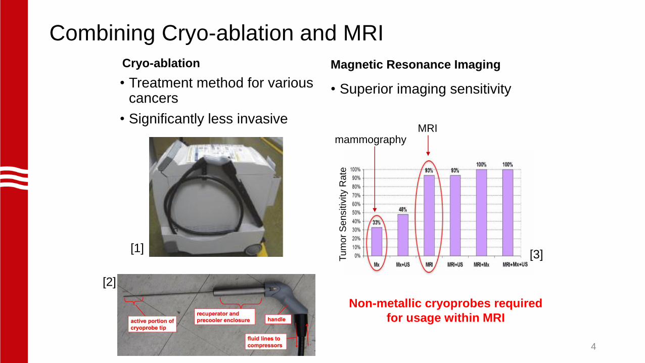
Combining Cryo-ablation and MRI
Cryo-ablation
• Treatment method for various cancers
• Significantly less invasive
Magnetic Resonance Imaging
• Superior imaging sensitivity
[1]
[2]
MRImammography
Tu
mo
r S
en
sitiv
ity R
ate
[3]
Non-metallic cryoprobes required
for usage within MRI
4

Commercial Options in the U.S.
Fluid Phigh (MPa) Cycle Company
LN2 0.15 Open Sanarus
LN2 0.15 Open IceCure Medical
Argon / Helium 30 Open Galil Medical
Argon / Helium 21/11.7 Open Endocare
N2O 5.16 Open Medtronic
N2O 5.16 Open Atricure
Mixture 1.5 Closed Cooper Surgical
Mixture 1.5 Closed Marvel MedTech
5
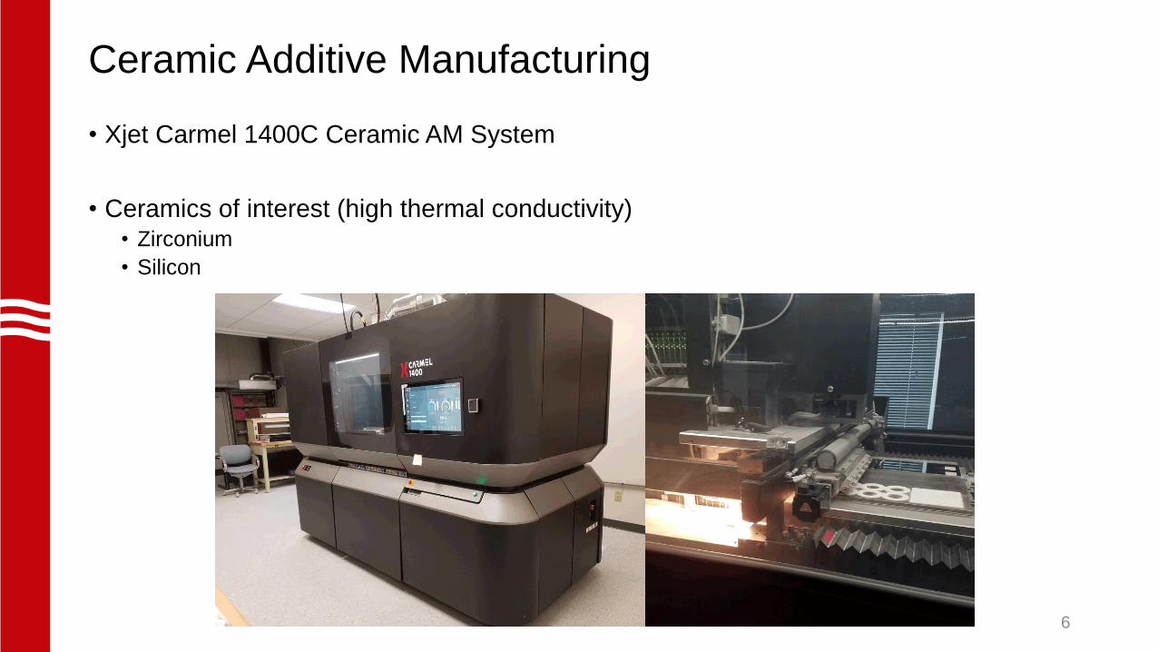
Ceramic Additive Manufacturing
• Xjet Carmel 1400C Ceramic AM System
• Ceramics of interest (high thermal conductivity)• Zirconium
• Silicon
6

Status of Current Experiments at UW-Madison
• Hydrostatic pressure testing up to 600 psi (4.15 MPa)• Operation requires 300 psi (2.07 MPa)
• Thermal testing – not yet complete
G10 support
structure
Type J
Thermocouples
NPT fittings to
plumbing
Zirconium
cryo-probe7
Test piece dimensions:
• 7.4 mm OD
• 1.6 mm ID
• 9.6 cm long

Thermodynamic Modelling
• Tube-in-tube HX features:• Two-phase flow correlations
• Axial conduction
• Gas mixture properties
• Discretized heat exchanger
Model represents this
section of the cycle, or
compressed gas venting to
ambient air
[2]
Target: 10 [W] of cooling power at 170 [K] 8
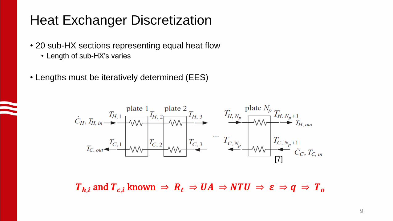
Heat Exchanger Discretization
• 20 sub-HX sections representing equal heat flow• Length of sub-HX’s varies
• Lengths must be iteratively determined (EES)
𝑻𝒉,𝒊 and 𝑻𝒄,𝒊 known ⇒ 𝑹𝒕 ⇒ 𝑼𝑨 ⇒ 𝑵𝑻𝑼 ⇒ 𝜺 ⇒ 𝒒 ⇒ 𝑻𝒐
[7]
9

Mixed Gas Properties
• Gas mixture optimized as described by Detlor et. Al. [4,5]
• Largest minimum ∆ℎ𝑇
• Property tables extracted from REFPROP [6], varying T and P
• 2D interpolation → estimate fluid properties for any T and P combination (EES)
150 200 250 300
x 105
0
2
4
6
8
Temperature [K]E
nth
alp
y [
J/k
g]
0.1 MPa0.1 MPa
0.5 MPa0.5 MPa
1 MPa1 MPa
1.5 MPa1.5 MPa
2 MPa2 MPa
𝟎. 𝟔𝑪𝟑𝑯𝟖 + 𝟎. 𝟑𝟔𝑪𝑯𝟒 + 𝟎. 𝟎𝟒𝑵𝟐
Ex: Mixture enthalpy data 10

Two-phase Flow Correlations
Heat Transfer Coefficient
Correlation
Pressure Drop
Correlation
Single-Phase Gnielinski (1976) [8] Zigrang and Sylvester
(1982) [9]
Two-Phase
Boiling
Shah (1982) [10] Ould Didi et al. (2002) [11]
Two-Phase
Condensation
Dobson and Chato (1998)
[12]
Ould Didi et al. (2002) [11]
• Appropriate correlations chosen from conditional EES procedures
• Mixture quality data is required
11

Modelling Results
• Pressure and Temperature profiles generated
• Other values of interest:• Effectiveness – 82%
• Mass flow rate – 0.2 [g/s]
• Effective length required – 1.25 [m]
• Helically coiled HX length – 16.3 [cm]
12
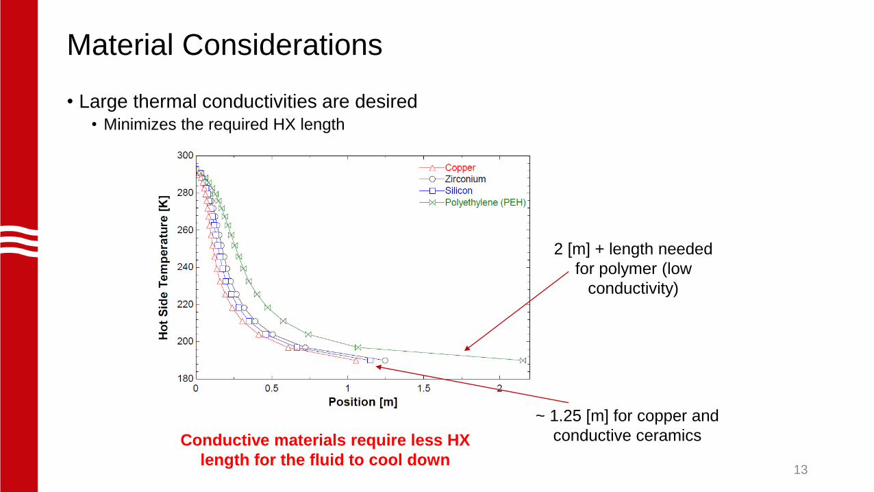
Material Considerations
• Large thermal conductivities are desired• Minimizes the required HX length
Conductive materials require less HX
length for the fluid to cool down
2 [m] + length needed
for polymer (low
conductivity)
~ 1.25 [m] for copper and
conductive ceramics
13

Thermal conductivity values
14

Helical Geometry
• Results suggest a 1.25 [m] long heat exchanger
• 2 [mm] outer diameter tube-in-tube heat exchanger
• Length reduced by helical coiling
~ 16 [cm]
~ 1
[cm
]
Geometry is possible with additive manufacturing
2 [mm]
1 [mm]
15

References[1] Cooper Surgical 2015 Her Option Cryoablation Therapy System User Manual
www.coopersurgical.com
[2] Skye H and Pfotenhauer J 2018 Joule thompson cryocoolers and cryoablation
Applications of Cryocoolers
[3] Harter R 2017 Series a executive summary (Middleton: Marvel Medtech, LLC)
www.marvelmedtech.com
[4] Detlor J, Pfotenhauer J and Nellis G 2017 Mixture optimization for mixed gas joule-thomson
cycle IOP Conf. Series: Materials Science and Engineering 278 012045
[5] Detlor J, Pfotenhauer J, and Nellis G 2018 Experimental investigation of mixture optimization
for mixed joule-thomson cycle Cryocoolers 20 (Boulder: ICC Press)
[6] Lemmon E, Huber M, and McLinden M 2013, Nist standard reference database 23:
reference fluid thermodynamic and transport properties-refprop version 9.1 National Institute of Standards and
Technology
[7] Nellis G and Klein S 2009 Heat Transfer (Cambridge; New York: Cambridge University Press)
chapter 8 p 916
[8] Gnielinski V 1976 New equations for heat and mass transfer in turbulent pipe and channel
flow Int. Chem. Eng. 16 359–68
[9] Zigrang D and Sylvester N 1982 Explicit approximations to the solution of colebrook’s
friction factor equation American Institute of Chemical Engineering Journal 28 514–15
[10] Shah M 1982 Chart correlation for saturated boiling heat transfer: equations and further
study ASHRAE Transactions 88 185–86
[11] Ould Didi M, Kattan N and Thome J 2002 Prediction of two-phase pressure gradients of
refrigerants in horizontal tubes International Journal of Refrigeration 25 935-47
[12] Dobson M and Chato J 1998 Condensation in smooth horizontal tubes Journal of
Heat Transfer 120 193–213
16


