Page 1
MRI (Mk3) Technical Manual P&B Engineering
20/7/99 Page 0 Issue 1
MRI (Mk3) Digital Overcurrent & Earth Fault Relay
P&B Engineering
Belle Vue Works
Boundary Street
Manchester
M12 5NG
Tel: 0161 230 6363
Fax: 0161 230 6464
Internet Address http://www.pbeng.co.uk
E-mail [email protected]
Page 2
MRI (Mk3) Technical Manual P&B Engineering
20/7/99 Page ii Issue 1
Contents
1. INTRODUCTION. .............................................................................................................................................................1
2. APPLICATION. .................................................................................................................................................................2
3. FEATURES AND CHARACTERISTICS........................................................................................................................3
4. DESIGN...............................................................................................................................................................................4
4.1. CONNECTIONS. ...............................................................................................................................................................4
4.1.1. Analogue input circuits...........................................................................................................................................8
4.1.2. Output relays. .........................................................................................................................................................8
4.1.3. Remote data communication. .................................................................................................................................9
4.2. FRONT PANEL. ................................................................................................................................................................9
4.2.1. Display....................................................................................................................................................................9
4.2.2. LED Indicators. ....................................................................................................................................................10
4.2.3. Push Buttons.........................................................................................................................................................11
4.3. CODE JUMPERS.............................................................................................................................................................11
4.3.1. Password Programming. ......................................................................................................................................12
4.3.2. Reset Function. .....................................................................................................................................................12
5. WORKING PRINCIPLES. .............................................................................................................................................13
5.1. ANALOGUE CIRCUITS....................................................................................................................................................13
5.2. DIGITAL CIRCUITS. .......................................................................................................................................................13
5.3. POWER SUPPLY.............................................................................................................................................................13
5.4. PHASE FAULT DIRECTIONAL FEATURE (OPTIONAL). ......................................................................................................14
5.5. EARTH FAULT DIRECTIONAL FEATURE (OPTIONAL). ......................................................................................................15
5.5.1. Earth fault direction feature for isolated or compensated earthed networks. ......................................................15 5.5.1.1. Isolated Systems. ...............................................................................................................................................................15
5.5.1.2. Compensated System.........................................................................................................................................................17
5.5.2.1. Solidly Earthed System. ....................................................................................................................................................18
5.5.2.2. Resistive Earthed System. .................................................................................................................................................19
5.6. REQUIREMENTS FOR THE MAIN CURRENT TRANSFORMERS. .........................................................................................20
5.7. BLOCKING INPUT. .........................................................................................................................................................20
5.8. RESET INPUT. ...............................................................................................................................................................20
5.9. RESET DELAY & DWELL TIME......................................................................................................................................21
5.9.1. Reset Delay...........................................................................................................................................................21
5.9.2. Dwell Time............................................................................................................................................................21
5.10. CIRCUIT BREAKER FAILURE PROTECTION (TCBFP). ......................................................................................................21
5.11. DISPLAY OF PICK-UP EVENT........................................................................................................................................21
5.12. DISPLAY OF MEASURING VALUES AS PRIMARY QUANTITIES (IPRIM PHASE). ..................................................................21
5.13. DISPLAY OF EARTH CURRENT AS PRIMARY QUANTITY (IPRIM EARTH). ........................................................................22
5.14. DISPLAY OF RESIDUAL VOLTAGE UE AS PRIMARY QUANTITY (UPRIM/USEC).................................................................22
6. OPERATION AND SETTING........................................................................................................................................23
6.1. LAYOUT OF THE CONTROL ELEMENTS. ..........................................................................................................................23
6.2. RELAY SETTING PRINCIPLES. .........................................................................................................................................23
6.2.1. Password protected parameter adjustment. .........................................................................................................24
6.3. SETTING PROCEDURE. ...................................................................................................................................................25
6.3.1. Starting current for phase overcurrent relay (I>). ...............................................................................................25
6.3.2. Time current Characteristic for phase overcurrent relay (CHAR I>)..................................................................25
6.3.3. Tripping time delay or time multiplier for phase overcurrent relay (tI>). ...........................................................25
6.3.4. Current setting for high set stage of phase overcurrent relay (I>>)....................................................................26
6.3.5. Tripping time delay for high set stage of phase overcurrent relay (tI>>). ..........................................................26
6.3.6. Starting current for earth fault relay (IE>). .........................................................................................................26
6.3.7. Time Current characteristic for earth fault relay (CHAR IE). .............................................................................26
6.3.8. Tripping time delay or time multiplier for earth fault relay (tIE>). .....................................................................26
6.3.9. Current setting for high set stage of earth fault relay (IE>>)..............................................................................27
6.3.10. Tripping time delay for high set stage of earth fault relay (tIE>>). ..................................................................27
Page 3
MRI (Mk3) Technical Manual P&B Engineering
20/7/99 Page iii Issue 1
6.3.11. Earthing type. .....................................................................................................................................................27 6.3.11.1. COS/SIN Measurement. ..................................................................................................................................................27
6.3.11.2. SOLI/RES Setting. ..........................................................................................................................................................27
6.3.12. Residual Earth Fault Voltage (VE). ...................................................................................................................27
6.3.13. Residual Earth Fault Voltage Measurement Method. ........................................................................................27
6.3.14. Earth Fault Response. ........................................................................................................................................27
6.3.15. Nominal frequency..............................................................................................................................................27
6.3.16. Assignments Of The Blocking Inputs. ................................................................................................................28
6.3.17. Blocking Of Protection Functions. ....................................................................................................................28
6.3.18. Programming Of Output Relays. .......................................................................................................................29
6.3.19. Parameter Switch. ..............................................................................................................................................31
6.3.20. Fault Recorder. .................................................................................................................................................31 6.3.20.1. Number of the fault recordings........................................................................................................................................31
6.3.20.2. Adjustment of trigger occurrences...................................................................................................................................32
6.3.20.3. Pre-trigger time (Tpre) ......................................................................................................................................................32
6.3.21. Adjustment of the clock.......................................................................................................................................32
6.3.22. Communication Settings. ....................................................................................................................................32 6.3.22.1. Slave Address. .................................................................................................................................................................32
6.3.22.2. Baud Rate. .......................................................................................................................................................................32
6.3.22.3. Parity. ..............................................................................................................................................................................33
6.3.23. Reset Setting (For Inverse Time Overcurrent Function). ...................................................................................33
6.3.24. Reset Setting (For Inverse Time Earth Fault Function). ....................................................................................33
6.3.25. Dwell Time..........................................................................................................................................................33
6.3.26. Relay Characteristic Angle (RCA)......................................................................................................................33
6.3.27. Pick Up Value For Residual Voltage UE. ...........................................................................................................33
6.3.28. Setting Summary.................................................................................................................................................34
6.4. INDICATION OF MEASURED VALUES AND FAULT DATA. .................................................................................................36
6.4.1. Indication of measured values..............................................................................................................................36 6.4.1.1. Measured Values as a Primary Value. ...............................................................................................................................37
6.4.2. Indication of fault data. ........................................................................................................................................38
6.4.3. Fault Recording....................................................................................................................................................39
6.5. TEST TRIP. ....................................................................................................................................................................40
6.6. RESET. ..........................................................................................................................................................................40
6.6.1. Hand reset. ...........................................................................................................................................................40
6.6.2. Reset input. ...........................................................................................................................................................40
6.7. SETTING VALUE CALCULATION. ....................................................................................................................................41
6.7.1. Low set stage. .......................................................................................................................................................41
6.7.2. High set stage. ......................................................................................................................................................41
6.7.3. Characteristic curve. ............................................................................................................................................41
6.7.4. Low set stage time multiplier/time delay. .............................................................................................................41
6.7.5. High set stage time delay......................................................................................................................................41
7. RELAY CASE. .................................................................................................................................................................41
7.1. INDIVIDUAL CASE. ........................................................................................................................................................41
7.2. RACK MOUNTING. .........................................................................................................................................................42
7.3. TERMINAL CONNECTIONS. ............................................................................................................................................42
8. TEST AND MAINTENANCE.........................................................................................................................................43
8.1. POWER ON....................................................................................................................................................................43
8.2. TESTING THE OUTPUT RELAYS AND LEDS. ...................................................................................................................43
8.3. CHECKING THE SET VALUES..........................................................................................................................................43
8.4. SECONDARY INJECTION TEST .......................................................................................................................................44
8.4.1. Test Equipment .....................................................................................................................................................44
8.4.3. Checking the input circuits and measured values ................................................................................................44
8.4.4. Checking the operating and resetting values of the relay. ...................................................................................45
8.4.5. Checking the relay operating time........................................................................................................................45
8.4.6. Checking the high set element of the relay. ..........................................................................................................45
8.4.7. Example of a test circuit for MRI relay with directional feature..........................................................................46
8.4.8. Test circuit earth fault directional feature............................................................................................................48
8.4.9. Checking the external blocking and reset functions. ............................................................................................49
8.4.10. Test of the CB failure protection. .......................................................................................................................49
8.5. PRIMARY INJECTION TEST. ............................................................................................................................................49
8.6. MAINTENANCE. ............................................................................................................................................................50
Page 4
MRI (Mk3) Technical Manual P&B Engineering
20/7/99 Page iv Issue 1
9. TECHNICAL DATA........................................................................................................................................................51
9.1 MEASURING INPUT CIRCUITS.........................................................................................................................................51
9.2 AUXILIARY POWER SUPPLY............................................................................................................................................51
9.3 COMMON DATA .............................................................................................................................................................51
9.4 SETTING RANGES AND STEPS..........................................................................................................................................52
9.4.1 Definite time phase overcurrent relay ...................................................................................................................52
9.4.2 Inverse time phase overcurrent relay ....................................................................................................................53
9.4.3 Direction unit for phase overcurrent relay............................................................................................................54
9.4.4 Direction unit for earth fault relay ........................................................................................................................54
9.5. INVERSE TIME CHARACTERISTICS .................................................................................................................................55
9.5.1 Inverse time Equations ..........................................................................................................................................56
9.6 OUTPUT CONTACT RATINGS ...........................................................................................................................................57
9.7 TYPE TESTS ...................................................................................................................................................................58
9.8 HOUSING .......................................................................................................................................................................61
9.9 TERMINAL CONNECTION DETAILS .................................................................................................................................62
10. ORDER FORM ..............................................................................................................................................................63
Page 5
MRI (Mk3) Technical Manual P&B Engineering
20/7/99 Page 1 Issue 1
1. Introduction.
The application of powerful microprocessors opens a new chapter for power system protective
relaying. The digital processing of measured values and the ability to perform complex arithmetic and
logic operations, give digital protection relays significant performance and flexibility improvements
over their traditional analogue counterparts. Additional advantages - very small power consumption,
adaptability, self-supervision, fault diagnosis through fault data recording, smaller physical
construction and selectable relay characteristics - all combine to allow the implementation of accurate
and highly reliable protection schemes at a significantly reduced financial burden.
The development of microprocessor based protective relays and their introduction into the market has
been stimulated by the recent trend to replace analogue with digital equipment. This modern trend has
prompted the development of a new P&B protective relay family - the MR relay series. This
comprehensive family of protection relays can satisfy the demands of even the most complex
protection schemes:
MRI - Overcurrent Relay (Independent time/I.D.M.T + earth + directional facilities)
MRI-V - Voltage Dependent Overcurrent Relay
MSP - Voltage or Overcurrent (I.D.M.T + earth + directional) Relay
MREF - Restricted Earth Fault Relay
MRAR - Auto-Reclosing Relay
MRMF - Mains Failure Relay
MRVT - Voltage Protection
MRFT - Frequency Protection
MROS - Vector Surge
MRNS - Negative Sequence Relay
MRRP - Power Relay
MRCS - Check Synchronising Relay
MRFF - Field Failure Relay
MRDG - Differential Relay
The superiority of digital protective relaying over traditional analogue devices, as embodied by the
MR relay family, is summarised by the following features:
•••• Integration of many protective functions in a single compact case
•••• High accuracy owing to digital processing
•••• Digital relay setting with very wide setting ranges and fine setting steps
•••• Comfortable setting procedure through extensive human - relay dialogue
•••• Measured values and fault data indication by means of alpha-numeric display
•••• Data exchange with DCS/SCADA by means of RS485
•••• Operational reliability through self-supervision
The digital overcurrent and earth fault relay MRI, was designed as a universal overcurrent relay for
applications in medium voltage networks. A similar, but simplified version, the MIRI, with reduced
functions and without display, is also available. Similarly for protection against undervoltage,
overvoltage and neutral voltage displacement, a reduced function non-display relay, the MIRV is
available. To complement the MR series, a range of Auxiliary, Timing and Tripping devices are also
available. The MSP range of relays were added to create a new series of single pole, competitive
overcurrent or voltage protection relays. They have the added feature of a large LCD Display,
enabling greater display of data.
Page 6
MRI (Mk3) Technical Manual P&B Engineering
20/7/99 Page 2 Issue 1
2. Application.
The MRI is a universal digital multifunctional relay used for overcurrent and/or earth fault protection
in medium voltage networks with ring mains, parallel feeders or doubly infed lines. The protective
functions of the MRI are summarised as follows:
• Selectable protective functions between :
- Definite time overcurrent relay
- Inverse time overcurrent relay
• Inverse definite minimum time (IDMT) overcurrent relay with the following
selectable characteristics in accordance with BS 142 and IEC 60255-3:
- Normal Inverse
- Very Inverse
- Extremely Inverse
- RI-Inverse
- Long Time Inverse
• High set overcurrent unit with instantaneous or definite time function
• Two stage overcurrent relay both for phase and earth faults
• Built in direction unit for application to ring main or parallel feeders with adjustable relay
characteristic angle (Optional)
• Built in earth fault direction unit for application to power system networks with
solid/resistive neutral earthing or isolated/arc suppressing coil (Peterson Coil) neutral
earthing. (Optional)
• Two stage (Low and High Set) earth fault protection with definite or inverse time
characteristics
• Reset time selectable for inverse time characteristics ("pecking faults")
Furthermore, the MRI relay can be employed as back-up protection for distance and differential
protective relays.
Page 7
MRI (Mk3) Technical Manual P&B Engineering
20/7/99 Page 3 Issue 1
3. Features and characteristics.
• Complete digital processing of the sampled measured values
• Digital filtering of measured values using discrete fourier analysis to suppress high
frequency harmonics and d.c component induced by faults or system operations
• Extremely wide setting ranges with fine setting steps
• Two Parameter Sets
• Unauthorised user access control through password protection
• User defined password
• Continuous self-supervision of software and hardware
• Outstanding design flexibility for easy selection of appropriate operational scheme
for numerous applications
• Numerical display of setting values, actual measured values and their
active/reactive components and memorised fault data etc.
• Display of measuring values as primary quantities
• Blocking e.g. of high set element (e.g. for selective fault detection through
downstream overcurrent protection units after unsuccessful Auto Reclose)
• Storage of trip values and switching off time (tCBFP) of 5 fault occurrences
• Recording of up to eight fault occurrences with time stamp
• Display of Date and Time
• Serial data communication facilities via RS485 interface with NETWORK GOLD
or Modbus RTU (Note For Modbus no fault recording is available)
• Wide voltage range for DC or AC power supply
• Withdrawable modules with automatic short circuit of C.T. inputs
• Circuit Breaker Failure Protection
• Programmable Output Relays
• Suppression of indication after an activation
Page 8
MRI (Mk3) Technical Manual P&B Engineering
20/7/99 Page 4 Issue 1
4. Design.
4.1. Connections.
Application Diagram; Overcurrent and Earth Fault Directional
P O W E R
S U P P L Y
1 2 C A S E
S u p p ly
1 4
I3
M R I- IE DT y p ic a l E a r th in g S h o w n
5 4 5 55 3E x te r n a l R e s e t B lo c k in g In p u t
L N L
R E L A Y 13 3
3 1
2 9
3 2
3 03 4
4 85 2
5 0
4 5
4 3
4 1
4 4
4 24 6
4 0
3 8
3 6
3 7
3 53 9
+
7 9 1 0
G n d-
4 75 1
4 9
S E L F S U P E R V IS IO N
R E L A Y 4
R E L A Y 3
R E L A Y 2
R S 4 8 5
1 9
I2
1 5
1 7
I1
V 1
N
V 2
V 3
2 1
2 2
2 3
2 4
2 5
2 6
2 7
2 8
L 1
L 2
L 3
I1
I2
I3
IE
S 2P 2
P 1
S 1
A lte rn a t iv eE a r th in g
Application Diagram; Overcurrent and Only Earth Fault Directional
P O W E R
S U P P L Y
1 2 C A S E
S u p p ly
M R I-I-E X
T yp ica l E arth in g S h o w n
5 4 5553E x te rna l R e s e t B lo c king Inp ut
L N L
33
31
29
32
3034
4852
50
45
43
41
44
4246
40
38
36
37
3539
4751
49
S E L F S U P E R V IS IO N
+
7 9 10
G n d-R S 4 85
L 1
L 2
L 3
14
I319
I2
15
17
I1
V 1
N
V 2
V 3
Alte rn a tiveE a rth in g
21
22
23
24
25
26
I1
I2
I3
S 2P 2
P 1
S 1
IE
27
28
C B C T
R E L AY 1
R E L AY 4
R E L AY 3
R E L AY 2
Page 9
MRI (Mk3) Technical Manual P&B Engineering
20/7/99 Page 5 Issue 1
Application Diagram; Overcurrent and Earth Fault
P O W E R
S U P P L Y
1 2 C A S E
S u p p ly
M R I-IET yp ic a l E a rth in g S h o w n
5 4 555 3
E x te rna l R e s e t B lo c k in g Inp u t
L N L
3 3
3 1
2 9
3 2
3 03 4
4 85 2
5 0
4 5
4 3
4 1
4 4
4 24 6
4 0
3 8
3 6
3 7
3 53 9
+
7 9 1 0
G n d-
4751
49
S E L F S U P E R V IS IO N
R S 4 85
21
22
2 3
2 4
2 5
2 6
2 7
2 8
L 1
L 2
L 3
I1
I2
I3
IE
S 2P 2
P 1
S 1
R E L A Y 1
R E L A Y 4
R E L A Y 3
R E L A Y 2
Application Diagram; Overcurrent and Earth Fault -Special Export Version
P O W E R
S U P P L Y
1 2 C A S E
S u p p ly
M R I-IE KT yp ic a l E a rth in g S h o w n
54 5 55 3
E x te rn a l R e s e t B lo c k in g In p u t
L N L
3 3
3 1
2 9
3 2
3 03 4
4 85 2
5 0
4 5
4 3
4 1
4 4
4 24 6
4 0
3 8
3 6
3 7
3 53 9
+
7 9 1 0
G n d-
4751
49
S E L F S U P E R V IS IO N
R S 4 85
2 1
2 2
23
24
25
26
27
28
L 1
L 2
L 3
I1
I2
I3
IE
S 2P 2
P 1
S 1
F O R T R IP /A L A R M F U N C T IO N S , R E F E R T O 4 .1 .2 .
R E L A Y 1
R E L A Y 4
R E L A Y 3
R E L A Y 2
Page 10
MRI (Mk3) Technical Manual P&B Engineering
20/7/99 Page 6 Issue 1
Application Diagram; Earth Fault Directional
T y p ic a l e a r th in g s h o w n
↓
A lte rn a tiv eE a r th in g
P O W E R
S U P P L Y
1 2 C A S E
S u p p ly
M R I-E X
5 4 5 55 3E x te rn a l R e s e t B lo c k in g In p u t
L N L
3 3
3 1
2 9
3 2
3 03 4
4 85 2
5 0
+
7 9 1 0
G n d-
4 75 1
4 9
S E L F S U P E R V IS IO N
R S 4 8 5
L 1
1 9
1 4
1 5
1 7
L 3
N
L 1
L 2
L 2
L 3
IE
2 7
2 8
C B C T
M R I-E D
R E L A Y 1
R E L A Y 4
Application Diagram; Earth Fault
P O W E R
S U P P L Y
1 2 C A S E
S u p p ly
M R I-E
5 4 5 55 3E x te rn a l R e s e t B lo c k in g In p u t
L N L
3 3
3 1
2 9
3 2
3 03 4
4 85 2
5 0
+
7 9 1 0
G n d-
4 75 1
4 9
S E L F S U P E R V IS IO N
R S 4 8 5
T y p ic a l e a r th in g s h o w n
L 1
L 2
L 3
IE
2 7
2 8
C B C T
R E L A Y 1
R E L A Y 4
Page 11
MRI (Mk3) Technical Manual P&B Engineering
20/7/99 Page 7 Issue 1
Application Diagram; Overcurrent
PO W E R
SU PPL Y
1 2 C AS E
S upply
M R I-I
T yp ica l E arth ing Sh ow n
54 5553Externa l R esetB lo cking Inp ut
L N L
33
31
29
32
3034
4852
50
45
43
41
44
4246
40
38
36
37
3539
+
7 9 10
G nd-
S ELF S U PE R V IS IO N
R S 485
21
22
23
24
25
26
L 1
L2
L3
I1
I2
I3
S 2P 2
P 1
S 1
FO R TR IP /A L AR M FU N C TIO N S , R E FE R TO 4.1 .2.
R E L AY 1
R E L AY 4
R E L AY 3
R E L AY 2
Application Diagram; Overcurrent Directional
P O W E R
S U P P L Y
1 2 C A S E
S u p p ly
1 4
I3
M R I- IDT y p ic a l E a r th in g S h o w n
5 4 5 55 3E x te rn a l R e s e t B lo c k in g In p u t
L N L
3 3
3 1
2 9
3 2
3 03 4
4 85 2
5 0
4 5
4 3
4 1
4 4
4 24 6
4 0
3 8
3 6
3 7
3 53 9
+
7 9 1 0
G n d-
S E L F S U P E R V IS IO N
R S 4 8 5
1 9
I2
1 5
1 7
I1
V 1
N
V 2
V 3
2 1
2 2
2 3
2 4
2 5
2 6
L 1
L 2
L 3
I1
I2
I3
S 2P 2
P 1
S 1
A lte rn a t i v eE a r th in g
R E L A Y 1
R E L A Y 4
R E L A Y 3
R E L A Y 2
Page 12
MRI (Mk3) Technical Manual P&B Engineering
20/7/99 Page 8 Issue 1
Application Diagram; Overcurrent Directional
Alternative Application Diagram using a 'v' connected voltage transformer 2 phase input.
P O W E R
S U P P L Y
1 2 C A S E
S u p p ly
1 4
I3
M R I- IDT y p ic a l E a r th in g S h o w n
5 4 5 55 3E x te r n a l R e s e t B lo c k in g In p u t
L N L
3 3
3 1
2 9
3 2
3 03 4
4 85 2
5 0
4 5
4 3
4 1
4 4
4 24 6
4 0
3 8
3 6
3 7
3 53 9
+
7 9 1 0
G n d-
S E L F S U P E R V IS IO N
R S 4 8 5
1 9
I2
1 5
1 7
I1
V 1
N
V 2
V 3
2 1
2 2
2 3
2 4
2 5
2 6
L 1
L 2
L 3
I1
I2
I3
S 2P 2
P 1
S 1
N u e tra l N o tC o n n e c t e d
R E L A Y 1
R E L A Y 4
R E L A Y 3
R E L A Y 2
4.1.1. Analogue input circuits.
The constantly monitored measuring values are galvanically decoupled, filtered and finally fed to the
analogue/digital converter. The protection unit receives these analogue input signals of the phase
currents I1, I2, I3 and residual current IE, and phase voltages V1, V2, V3 with a star point, each via
separate input transformers.
The residual voltage Ve, required for MRI units with earth fault directional facility, is formed
internally in the secondary circuit of the voltage transformers. Where only the earth fault directional
facility is required (ie phase fault directional facility unused) the residual voltage from an existing
open delta winding may be directly connected across L1 & N.
4.1.2. Output relays.
The MRI has five output relays, with single or dual pole change-over contacts as detailed in the
previous diagrams. With the exception of Relay 5, which is used only for self supervision output and
which is normally energised, the other Relays (1 to 4) are programmable to the users specification
(see Section 6.3.18). The factory default settings are given in table shown in section 6.3.18.
In the alarm mode, alarm outputs operate upon energisation.
Page 13
MRI (Mk3) Technical Manual P&B Engineering
20/7/99 Page 9 Issue 1
4.1.3. Remote data communication.
As an option, the MRI may have an RS485 interface for remote data communication with a control
centre. The unit provides the following information:
• Measured phase fault current values
• Measured earth fault current values
• Status signals
• Self supervision alarm signal
• Actual measured current values
• Relay settings
• Phase fault signalling
• Earth fault signalling
There is a choice in the communication protocol of the MRI relay. Both Modbus RTU and
NETWORK GOLD is available. Unfortunately fault recording is not available in a relay with
Modbus RTU.
4.2. Front Panel.
The front panel of the MRI comprises the following operation and indication elements:
• Alphanumeric display (4 Digits)
• 5 push buttons for setting and other operations
• Up to 23 LEDs for measured value indication and setting
4.2.1. Display.
The measured and set values, and recorded fault data, are shown alphanumerically on the display. The
meaning of the displayed values is easily interpreted from the LED indicators on the front panel. See
Section 6.4. for more details.
Page 14
MRI (Mk3) Technical Manual P&B Engineering
20/7/99 Page 10 Issue 1
4.2.2. LED Indicators.
The LEDs to the left of the display indicate measuring or tripping values. The purpose of the
corresponding LED is identified by the adjacent inscription, (e.g. L2 for current in phase 2).
The full list of LEDs are as follows:-
LED Indicates
L1 Current Phase 1
L2 Current Phase 2
L3 Current Phase 3
E Earth Current
Date And Time
IP Active Component
IQ Reactive Component
Relay Characteristic Angle / Direction *
RS Serial Address
FR Fault Recording
P2 Parameter Switch
C.B. Circuit Breaker Fail Protection
I> Pickup Current For Phase Overcurrent
CHAR I> Time Current Characteristics for Phase O/C
tI> Tine Delay or Time Multiplier for Phase O/C
I>> Current Setting for High Set Element
tI>> Time Delay for High Set Element
IE> Pickup Current for Earth Fault Element
CHAR IE Time Current Characteristics for E/F
tIE> Time Delay or Time Multiplier for E/F
IE>> Current Setting for High Set Element of E/F
tIE>> Trip Delay for High Set Element of E/F
UE> Residual Voltage
* For forward direction this LED is illuminated GREEN, and
For reverse direction this LED is illuminated RED.
Up to ten LEDs support the setting menu selection. They are arranged at the characteristic points on
the setting curves. Upto five are for phase fault characteristic and upto five are for earth fault
characteristic. Each indicate the corresponding menu point selected.
Page 15
MRI (Mk3) Technical Manual P&B Engineering
20/7/99 Page 11 Issue 1
4.2.3. Push Buttons.
The front panel contains five push buttons used for setting, measuring and other user functions.
The individual setting and measuring values can be selected in turn by pressing the
<SELECT/RESET> push button. This button also resets the relay if pressed for approximately 3
seconds.
The <UP> and <DOWN> push buttons are for incrementing and decrementing any selected
parameter. Continuous pressing of these push buttons will cause the parameter to change at an
increased rate.
The <ENTER> push button is used to transfer the indicated value to the internal parameter memory.
An unintended or unauthorised change of the selected parameter can be avoided through the
password protection facility.
The <TRIP> push button is used to test the output relay circuits, both for tripping and signalling.
This operation is also password protected.
4.3. Code Jumpers.
Behind the front panel of the MRI are two code
jumpers used to preset the following functions:
•••• Password programming
•••• Reset functions
The following figure shows the position and
designation of the code jumpers.
Note. If you have a Surface Mount Board (with Wide
range power supplies) there will be two extra jumpers.
These jumpers are used to choose the input voltage for
the external reset and the blocking input. The two
jumpers should always be the same.
Jumper 4 – Input voltage upto 240V
Jumper 5 – Input voltage upto 110V
J3 J2 J1
Code Jumper ON
Code Jumper OFF
Front Board
Code Jumper
Pre Wide Range Post Wide RangePower Supply. Power Supply.
Page 16
MRI (Mk3) Technical Manual P&B Engineering
20/7/99 Page 12 Issue 1
4.3.1. Password Programming.
The MRI relay is normally delivered with the preset password "∧∧∧∧∧∧∧∧∧∧∧∧∧∧∧∧", it can be reprogrammed
using the removable code jumper J1. After power on and the pressing of any push button, the MRI
relay enquires for a new password with the text "PSW?" appearing on the display. A new password
is then entered by pressing a combination of <SELECT/RESET>, <UP>, <DOWN> or
<ENTER>, as chosen by the user. After the new password has been given, the relay module is
extracted from its case and code jumper J1 removed.
4.3.2. Reset Function.
Code jumper J3 - OFF
All output relays will be reset automatically after tripping, once the fault has been cleared.
Code jumper J3 - ON
All output relays remain activated and must be reset manually by pressing the <RESET> push
button, after the fault has been cleared.
Summarising the coding possibilities
Code jumper Function Code jumper Position Operation Mode
J1 Password OFF
ON
Normal position
Password programming
J3 Reset OFF
ON
Output relays will be reset
automatically.
Output relays will be reset
manually.
Page 17
MRI (Mk3) Technical Manual P&B Engineering
20/7/99 Page 13 Issue 1
5. Working Principles.
5.1. Analogue Circuits.
The incoming currents from the external current transformers are converted to internal signals in
proportion to the currents, via the internal input transducers and shunt resistors. The noise signals
caused by inductive and capacitive coupling are suppressed by an analogue RC filter circuit. The
analogue signals are fed to the A/D converter of the micro-processor and transformed to digital
signals through sample-hold circuits. The analogue signals are sampled with a sampling frequency
of 800 Hz, namely a sampling rate of 1.25 mS for every measured quantity.
In order to achieve a sensitive earth current measurement, an operational amplifier is connected to
the earth current input circuit before the analogue signal enters the A/D converter. The incoming
voltages from the external voltage transformers are fed to operational amplifiers through the input
transducers and RC filters. The analogue voltage signals are transformed into a logical binary signal,
which is used as a reference signal to detect fault direction. The residual voltage needed for earth
fault direction is formed internally from the secondary circuits of the input transducers.
5.2. Digital Circuits.
The essential component of the MRI relay is a powerful micro-controller. All of the operations,
from the analogue digital conversion to the relay trip decision, are carried out by the micro-
controller digitally. The relay program, located in EPROM, allows the CPU of the micro-controller
to calculate the three phase currents and earth fault current in order to detect a possible fault.
For the calculation of the current value, an efficient digital filter, based on the Fourier Analysis
(DFFT - Discrete Fast Fourier Transformation), is applied to suppress high frequency harmonics
and DC components caused by fault induced transients or other system disturbances. The actual
calculated current values are compared with the relay settings. When a current exceeds the starting
value the unit starts the corresponding time delay calculation. When the set time delay has elapsed, a
trip signal is given.
The relay setting values for all parameters are stored in EEPROM, so that the actual relay settings
cannot be lost, even in the event of auxiliary supply interruption. The micro-processor is supervised
through a built in "Watch-dog" timer. Should a failure occur the watch-dog timer resets the micro-
processor and gives an alarm signal via the self supervision output relay.
5.3. Power Supply.
A wide range auxiliary power supply is available:
Vaux = 16V to 360V DC
16V to 270V AC
Page 18
MRI (Mk3) Technical Manual P&B Engineering
20/7/99 Page 14 Issue 1
5.4. Phase Fault Directional feature (optional). An integral directional element is available within the MRI-IED, MRI-ED, MRI-I-EX & MRI-ID
relays.
In order to achieve the reliable detection of fault current flow direction, the relay uses an internal
quadrature connection.
With this method;
the reference voltage for phase current I1 is taken from phase to phase voltage V23,
the reference voltage for phase current I2 is taken from phase to phase voltage V31,
the reference voltage for phase current I3 is taken from phase to phase voltage V12,
This method ensures that whilst the voltage may decrease on the faulted phase(s), the reference
voltage should still be available. Note that the CT & VT connections should be made as shown in
the appropriate application diagram.
The directional element analyses the relation between operating current and reference voltage, to
determine the fault direction. This is related to the relay characteristic angle (range 15° to 83°) as
selected by the user. Typically a relay characteristic angle of 45° is chosen for transformer feeders
and 30° for plain feeders as shown in Figure 5.4.1. This relates to a system characteristic angle of
45º or 60º respectively, due to the internal quadrature connection.
Fig. 5.4.1 Trip / No Trip region for directional element in the MRI (phase overcurrent)
The trip zone indicated by Figure 5.4.1 illustrates the operation for phase current I1 related to both
the phase voltage V1, and the directionalising element from voltage V23.
The operate zone is effectively bounded ±90° about the system characteristic angle for current levels
exceeding the set level, as detailed in 6.3.1 and 6.3.4.
The use of an efficient directional algorithm and high sensitivity voltage measurement, enables
accurate assessment of the phase angle, even for close three phase faults. In order to prevent
incorrect assessment, four consecutive direction measurements must occur before a trip operation
can be allowed.
The different time delays or time multipliers for forward and reverse direction, as detailed in 6.3.3
& 6.3.5, enables the user to achieve a high degree of system grading.
System characteristic angle 45°,generally used for transformer feeders,or feeders "earthed" in front of the relay
No tripRegion
V1
V23
V12V31
V3V2
Trip zone45° lead through
135° lag
V '23
45°
System characteristic angle 60°generally used for plain feeders,"earthed" behind the relay
V1
V23
V12V31
V3V2
Trip zone30° lead through150° lag
V '23
60°
No tripRegion
Page 19
MRI (Mk3) Technical Manual P&B Engineering
20/7/99 Page 15 Issue 1
5.5. Earth fault directional feature (optional).
Within the MRI range, two versions of earth fault protection are available;
for application to:
Isolated or compensated earthed networks (5.5.1)
Solid or resistance earthed networks (5.5.2)
This selection must be made at the time of order.
5.5.1. Earth fault direction feature for isolated or compensated earthed networks.
5.5.1.1. Isolated Systems.
In an isolated system, although there is no direct connection between the system and earth, the
capacitance of cables and other equipment can effectively tie the system to earth. In the event of a
fault to earth, the disturbance causes a small capacitive current to flow which may be detected and
acted upon by the relay.
This residual current may be obtained by a Holmgreen connection of the line CT's. However, to
produce the required accuracy of measurement, a core balance CT should, in almost all cases, be
used.
In order to determine the fault direction a voltage reference is required. Usually, this is obtained
through the use of an additional broken delta winding on the Voltage Transformer. However, the
MRI range eliminates the need for this additional winding by forming the residual reference voltage
internally, from the three applied phase voltages. If this facility is employed, the applied voltages
must be obtained from either a 5 limb VT or 3 single phase VT's, and the measuring method
(6.3.13) should be set to "3PHA".
Where a broken delta winding is used, as shown in Figure 5.5.1.1(a), the measuring method (6.3.13)
should be set to "E-N".
Where a line VT is not available it is possible to use a secondary winding on the system earthing
transformer, as shown in Figures 5.5.1.1(b) & 5.5.1.1(c), and the measuring method (6.3.13) should
be set to "1:1".
15
14
MRI
a) Use of broken delta VT
15
14
MRIb) Use of earthing transformer
15
14
MRI
c) Use of generator/transformer earthing VT
G
Figure 5.5.1.1
Page 20
MRI (Mk3) Technical Manual P&B Engineering
20/7/99 Page 16 Issue 1
Since the relay must determine the fault direction by evaluating a capacitive current, a SINE
function is employed. i.e;
A faulted line produces a 90° lagging current, whilst,
a non-faulted line would reflect a 90° leading current.
Figure 5.5.1.2 Trip / No Trip region for earth fault in an isolated system (SIN selection).
The trip zone indicated by Figure 5.5.1.2 illustrates the operation for the earth fault current Ie related
to the residual voltage Ve, for an isolated system.
The operate zone is determined by analysis of the capacitive component of the fault current for
magnitudes exceeding the set level, as outlined in 6.3.6 & 6.3.9.
Trip Region (Sin)
Ve
I e
(Faulted Line)
ReflectedFault Current
(Non-faulted Line)
Page 21
MRI (Mk3) Technical Manual P&B Engineering
20/7/99 Page 17 Issue 1
5.5.1.2. Compensated System.
In a compensated earthed network the system is connected to earth via a reactance, matched to
balance the system capacitance. In the event of a fault to earth, the change in the balance of
capacitive current, between the phases, is compensated by the neutral earthing reactance.
Under these circumstances the relay must determine the direction of the fault by evaluating the
resistive current by using a COSINE function.
The residual current and voltage references are obtained as for an isolated system.
Figure 5.5.1.3 Trip/No Trip region for earth fault in a compensated system (COS selection).
The trip zone indicated by Figure 5.5.1.3 illustrates the operation for the earth fault current Ie related
to the residual voltage Ve, for an compensated system.
The operate zone is determined by analysis of the resistive component of the fault current for
magnitudes exceeding the set level, as outlined in 6.3.6 & 6.3.9.
Ve
I e
(Faulted Line)
ReflectedFault Current
(Non-faulted Line)
Trip Region (Cos)
Page 22
MRI (Mk3) Technical Manual P&B Engineering
20/7/99 Page 18 Issue 1
5.5.2. Earth fault direction feature for solidly connected or resistive earthed networks.
The residual current may be obtained by a Holmgreen connection of the line CT's. However, a
core balance CT may be used for improved accuracy.
In order to determine the fault direction a voltage reference is required. Usually, this is obtained
through the use of an additional broken delta winding on the Voltage Transformer. However, the
MRI range eliminates the need for this additional winding by forming the residual reference voltage
internally, from the three applied phase voltages. If this facility is employed, the applied voltages
must be obtained from either a 5 limb VT or 3 single phase VT's. Alternatively a broken delta
winding may be used, as shown in Figure 5.5.1.1(a).
5.5.2.1. Solidly Earthed System.
In a solidly earthed system, the fault current will lag the remaining phase voltage Vr by
approximately 70°. However, the internally formed reference voltage Ve "seen" by the relay, will be
approximately 180° to the remaining phase voltage. Thus the relay has a characteristic phase angle
of -110°, as shown in Figure 5.5.2.1 (Soli).
Figure 5.5.2.1 Trip/No Trip region for earth fault in a solid system.
The operate zone is effectively bounded ±90° about the relay characteristic angle for current levels
exceeding the set level, as detailed in 6.3.6 and 6.3.9.
Vr
Trip Region (Soli)
-110°
Ve
Relay characteristic angle -110,
relay selected for solidearthed system.
Page 23
MRI (Mk3) Technical Manual P&B Engineering
20/7/99 Page 19 Issue 1
5.5.2.2. Resistive Earthed System.
In a resistive earthed system, the fault current will be approximately in phase with the residual
voltage Vr. As with a solidly earthed system, the internally formed reference voltage Ve "seen" by
the relay, will be approximately 180° to the voltage. Thus the relay has a characteristic phase angle
of 170°, as shown in Figure 5.5.2.2 (Resi).
Figure 5.5.2.2 Trip/No Trip region for earth fault in a resistive earthed system.
Vr
170°
Ve
Relay characteristic angle 170,relay selected for resistanceearthed system.
Trip Region (Resi)
Page 24
MRI (Mk3) Technical Manual P&B Engineering
20/7/99 Page 20 Issue 1
5.6. Requirements for the main Current Transformers.
In order to ensure the correct operation of the MRI range of relays, protection class CT's must be
utilised. Instrument CT's are NOT a suitable alternative.
CT's should be chosen such that saturation, or loss of accuracy does not occur within the settings
and operation ranges of the relays. In the absence of known settings the following may be regarded
as an approximate guide.
Line CTs
For 1A secondary
CT class 5P20 or 10P20 2.5VA (Allowing for up to 1Ω of secondary lead resistance)
For 5A secondary
CT class 5P20 or 10P20 5VA (Allowing for up to 0.5Ω of secondary lead resistance)
Core Balance CTs
For solid and resistive earthed systems
CT Class 1.0/5P5, 2.5VA
For isolated/compensated systems where sensitive settings are required.
Special Core Balance CT Type Z, ratio 200mA/1.5mA for use with MRI-EX rated 1A.
Stabilising Resistor.
In the case where the earth fault input is supplied from the Holmgreen (residual) connection of 3
line CT's it may be necessary to fit an external stabilising resistor. Guildence on selecting a
suitable resistor is given in P&B Engineering Publication ref MR901.
NOTE.
with due regard to a suitable CT ratio and fault level capacity.
5.7. Blocking Input.
By applying a voltage within the auxiliary voltage operating range to terminals 55 - 54 ( terminal 54
is common to the RESET input ) the protection functions chosen by the user is blocked whilst the
voltage is applied, (see section 6.3.16).
5.8. Reset Input.
By applying a voltage within the auxiliary voltage operating range to terminals 53 - 54 ( terminal 54
is common to the BLOCKING input ) all output relays may be reset.
Page 25
MRI (Mk3) Technical Manual P&B Engineering
20/7/99 Page 21 Issue 1
5.9. Reset Delay & Dwell Time.
In order to provide better discrimination with Electromechanical relays two additional settings are
provided.
5.9.1. Reset Delay.
The reset delay delays the reset of the relay following a Flashing Fault (sometimes known as a
Pecking Fault) which simulates the time an electromechanical relay takes in order to “wind back” a
partially rotated Disk (IDMT). This may be selected as 0 or 60 seconds.
5.9.2. Dwell Time.
The dwell time, is an additional delay introduced on the output contacts used to prevent the contacts
opening during a tripping action. This may be selected as 0 or 200 mS.
5.10. Circuit Breaker Failure Protection (tCBFP).
The CB Failure Protection is based on supervision of phase currents during tripping events. This
protective function becomes active only after tripping. The test criterion is whether all phase curents
have dropped to <1% x In within tCBFP (Circuit Breaker Failure Protection adjustable between 0.1 -
1.6s) If one or more of the phase currents have not dropped to <1%xIn within this time, CB failure
is detected and the assigned output relay is activated. The CB failure protection function is
deactivated again as soon as all the phase currents have dropped to <1%xIn within tCBFP.
5.11. Display of Pick-up event.
If after a pick-up (starting) the existing current drops again below the pickup value, e.g. I>, without
a trip being initiated, LED I> signals that an activation has occurred by flashing fast. The LED
keeps falshing until it is reset again (push button <SELECT/RESET>). Flashing can be suppressed
when the parameter is set to NOFL. This applies also to the I>>, IE>, IE>> functions.
5.12. Display of Measuring values as primary quantities (Iprim phase).
With this parameter it is possible to show the indication as a primary measured value. For this
purpose the parameter must be set to be equal with the rated primary CT current. If the parameter is
set to "SEK" the measuring value is shown as a multiple of the rated secondary current.
Example:
The current transformer used is 1500/5A. The primary current is 1380A. The paramter is set to
1500A and on the display "1380 A" is shown. If the parameter is set to "SEK" the value shown on
the display is "0.92"xIn.
Note.
The pick-up value is set to a multiple of the rated secondary CT current.
Page 26
MRI (Mk3) Technical Manual P&B Engineering
20/7/99 Page 22 Issue 1
5.13. Display of Earth Current As Primary Quantity (Iprim earth).
The parameter of this function is to be set in the same way as that described under Section 5.12. If
the parameter is not set to "SEK" then the measuring value is shown as primary current in amperes
(this applies to MRI-IEX, MRI-IEK and MRI-EX as well). Apart from that the indication refers to
% of In.
5.14. Display of Residual Voltage UE as Primary Quantity (Uprim/Usec).
The residual voltage can be shown as primary measured value. For this parameter the
transformation ratio of the VT has to be set accordingly. If the parameter is set to "SEK", the
measuring value is shown as rated secondary voltage.
Example.
The voltage transformer used is 10kV/100V. The transformation ratio is 100 and this value has to be
set accordingly. If rated secondary voltage should be shown , the parameter is to be set to 1.
Page 27
MRI (Mk3) Technical Manual P&B Engineering
20/7/99 Page 23 Issue 1
6. Operation and setting
6.1. Layout of the control elements.
All control elements required for the operation and adjustment of the MRI are located on the front
panel. They are divided according to function into the three following groups:
• Alphanumeric Display: Indication of parameter set values, actual measured values and
recorded fault data.
• LED's: Indication of selected parameters and measured quantities.
• Push Buttons: Selection of parameter to be adjusted, quantity to be measured and
adjustment of parameter values. Where;
<SELECT / RESET> Selection of the parameter to be set and the relay quantities
to be measured. Continuous pressing as the reset function.
<UP> Increment of the setting values for the parameter selected.
<DOWN> Decrement of the setting values for the parameter selected.
<ENTER> Storage of the setting values for the selected parameter.
<TRIP> Testing of the output relay circuits.
6.2. Relay setting principles.
Up to ten basic relay parameters may be set by the user, dependent upon relay type;
Phase overcurrent:
• I> Starting current for phase overcurrent
• CHAR I> Time current characteristic for phase overcurrent
• tI> Tripping time delay for definite time overcurrent or time
multiplier for inverse time overcurrent
• I>> Current setting for high set overcurrent
• tI>> Tripping time delay for high set overcurrent
Earth Fault: (optional)
• IE> Starting current for earth fault
• CHAR IE Time current characteristic for earth fault
• tIE> Tripping time delay for definite time earth fault or
time multiplier for inverse time earth fault
• IE>> Current setting for high set earth fault
• tIE>> Tripping time delay for high set earth fault
By pressing the <SELECT/RESET> push button, the parameter to be modified is reached. The
corresponding LED illuminates on the curve and the present set value of the selected parameter is
indicated on the display. This set value may then be increased or decreased by pressing the <UP> or
<DOWN> buttons respectively. The selected set value is only stored after pressing the <ENTER>
push button and inputting the correct password. This means that adjustment of the unit is only
possible by authorised users.
Page 28
MRI (Mk3) Technical Manual P&B Engineering
20/7/99 Page 24 Issue 1
6.2.1. Password protected parameter adjustment.
The adjustment of all relay settings are password protected, however, to enable ease of adjustment,
for authorised users, application of the password is usually only required once for multiple
parameter adjustment. The following step by step sequence is given to illustrate the implementation
of the password protection facility, where a new relay setting is to be applied:
• After the present setting value has been selected and changed using the <UP>,
<DOWN> push buttons, the <ENTER> push button should be pressed.
• The message "SAV?" appears on the display, to confirm that the new setting value is
to be saved.
• After pressing <ENTER> again, the password will be requested. The message
"PSW?" is displayed.
• After the password has been given correctly, as indicated by the message "SAV!",
the new setting value may be stored by pressing the <ENTER> push button for at
least 3 seconds. The new setting parameter then reappears on the display.
A password consists of four push button operations. The pressed push buttons and their sequence
define the password. If the four push buttons are defined by the following symbols:
<SELECT/RESET> = S
<DOWN> = ∨∨∨∨
<UP> = ∧∧∧∧
<ENTER> = E
Then a password "∨∨∨∨E∧∧∧∧S" is achieved by the following sequence:
<DOWN> <ENTER> <UP> <SELECT/RESET>.
After a password is given correctly, parameter setting is permitted for five minutes. Subsequent
parameter setting made within the five minute period after the password was inputted, does not
require renewed password entry. Furthermore, the valid period for parameter setting is automatically
extended for a further 5 minutes after each push button operation.
If no push button is pressed within the 5 minute period then the validity of the password will be
suspended. To enter further parameters after this period re-application of the password is required.
During the 5 minute period when changes may be made, a new set value, acknowledged by
"SAV?" then "SAV!" , may be stored by pressing <ENTER> for approximately 3 seconds.
Page 29
MRI (Mk3) Technical Manual P&B Engineering
20/7/99 Page 25 Issue 1
6.3. Setting procedure.
The following sections describe in detail the setting of all relay parameters. Some sections are only
applicable to the more comprehensive devices, eg earth or directional elements.
6.3.1. Starting current for phase overcurrent relay (I>).
The displayed setting value for this parameter is related to the nominal rated current (IN) of the
relay. Thus;
Starting current (IS) = Displayed Value x Rated Current (IN)
e.g. If Displayed Value = 1.25, then IS = 1.25 x IN
6.3.2. Time current Characteristic for phase overcurrent relay (CHAR I>).
By setting this parameter, one of the following four options is displayed:
DEFT - Definite Time
NINV - Normal Inverse
VINV - Very Inverse
EINV - Extremely Inverse
RINV - RI Inverse
LINV - Long Time Inverse
Any one of these six characteristics can be chosen by using the <UP> <DOWN> keys and can be
stored by pressing <ENTER>. For more details on the characteristic curves see Section 9.5.
6.3.3. Tripping time delay or time multiplier for phase overcurrent relay (tI>).
After the time/current characteristic has been selected, the time delay (or time multiplier) should be
changed accordingly. In order to avoid an unsuitable arrangement of relay modes the following
precautions are taken:
Adjustment of the time delay setting is automatically prompted for after a change in the set
time/current characteristic. LED tI> flashes yellow to remind the operator to change the time
delay setting accordingly. After pressing the <SELECT/RESET> push button, the present time
delay setting value is shown on the display. A new setting value may then be entered.
If the relay characteristic has been changed (e.g. from DEFT to NINV), but the time delay setting
has not, the relay will, after 5 minutes, automatically set itself to the most sensitive time setting
value available for that selected characteristic. The most sensitive time setting value implies the
fastest tripping for the selected relay characteristic. If the time delay or the time multiplier is set
out of range, "EXIT" appears on the display, and the low set stage of the relay is blocked.
Page 30
MRI (Mk3) Technical Manual P&B Engineering
20/7/99 Page 26 Issue 1
Where the MRI is fitted with a directional element, the different tripping time delays or time
multipliers may be chosen for both forward and reverse faults.
When setting the tripping time delay, the set value for forward faults appears on the display first
and the LED under the "arrows" illuminates GREEN. The set value may be changed with the
<UP> and <DOWN> push buttons, and then stored. By pressing the <SELECT/RESET>
button the tripping time delay for reverse faults appears on the display and indicator changes
from GREEN to RED.
If the time delays are set equally for both forward and reverse faults, the relay trips in both cases
with the same time delay, effectively nullifying the directional feature. If the time delay for
reverse faults is set out of range, "EXIT" on the display, the relay is blocked for reverse faults.
The low set stage of the overcurrent relay may also be blocked via terminals 54 and 55 (see
Section 6.3.17).
It is also possible to inhibit the alarm relay for a fault in the reverse direction. The display shows
either "NOWA" - No alarm when a fault occurs in the reverse direction, or "WBAK" - Alarm
relay is activated when a fault occurs in the reverse direction. During this procedure the LED is
illuminated RED.
6.3.4. Current setting for high set stage of phase overcurrent relay (I>>).
The current setting value of this parameter is related to the nominal rated current of the relay.
Thus;
I>> = Displayed Value x Rated Current (IN)
e.g. If Displayed Value = 20, then I>> = 20 x IN
The high set stage of the overcurrent relay is blocked if the setting value is set to "EXIT".
The high set stage may also be blocked via terminals 54/55, see Section 6.3.17.
6.3.5. Tripping time delay for high set stage of phase overcurrent relay (tI>>).
Independent from the chosen tripping characteristic for I>, the high set stage I>> always has a
definite time tripping characteristic. An trip delay value in seconds appears on the display.
The setting procedure for forward or reverse faults described in paragraph 6.3.3 is also valid for the
tripping time of the high set stage.
6.3.6. Starting current for earth fault relay (IE>).
(Similar to 6.3.1)
6.3.7. Time Current characteristic for earth fault relay (CHAR IE).
(Similar to 6.3.2)
6.3.8. Tripping time delay or time multiplier for earth fault relay (tIE>).
(Similar to 6.3.3)
Page 31
MRI (Mk3) Technical Manual P&B Engineering
20/7/99 Page 27 Issue 1
6.3.9. Current setting for high set stage of earth fault relay (IE>>).
(Similar to 6.3.4)
6.3.10. Tripping time delay for high set stage of earth fault relay (tIE>>).
(Similar to 6.3.5)
6.3.11. Earthing type.
6.3.11.1. COS/SIN Measurement.
Where an isolated or compensated earthed system version of the relay is supplied, the directional
element for earth faults must be set to SIN or COS as appropriate. Please refer to Section 5.5.1 for
more details.
6.3.11.2. SOLI/RES Setting.
Where a solid or resistive earthed system version of the relay is supplied, the directional element for
earth faults must be set to SOLI or RESI as appropriate. Please refer to Section 5.5.2 for more
details.
6.3.12. Residual Earth Fault Voltage (VE).
Operation of the earth fault (directional) element is inhibited for residual voltage below this preset
value, (isolated earth system).
6.3.13. Residual Earth Fault Voltage Measurement Method.
The measuring method must be set to "3PHA", "E-N" or "1:1" as required. (5.5.1, isolated earth
system).
6.3.14. Earth Fault Response.
The response to earth faults may be selected to "TRIP" or "WARN", ie to allow an alarm without
causing a trip function, (isolated earth system).
6.3.15. Nominal frequency.
The FFT Algorithm employed requires the nominal frequency as a parameter for correct digital
filtering of the input currents.
By pressing <SELECT> the display shows "f=50" or "f=60". The desired nominal frequency may
then be selected and stored.
Page 32
MRI (Mk3) Technical Manual P&B Engineering
20/7/99 Page 28 Issue 1
6.3.16. Assignments Of The Blocking Inputs.
The blocking input of the MRI relays can be programmed so that the blocking input will only block
certain functions. The blocking inputs are found at the beginning of assignment mode. By pressing
push buttons <ENTER> and <TRIP> simultaneously, the assignment mode is selected.
The first function that can be blocked has its LED light up and the display shows whether it is
blocked or not. To switch the blocking on (display shows BLOC) or off (NOBL) press the
<VALUE UP> or <VALUE DOWN> buttons and then save the parameter.
The following functions can be blocked.
Low Set Overcurrent
High Set Overcurrent
Low Set Earth Fault Overcurrent
High Set Earth Fault Overcurrent
The assignment mode can be terminated at any time by pressing the <SELECT/RESET> push
button for approximately 3 seconds.
6.3.17. Blocking Of Protection Functions.
The blocking function of the MRI can be set according to requirement. By applying the auxiliary
voltage to 55 and 56, the functions chosen by the user can be blocked. Setting of the parameter
should be done as follows:
1.) When pressing push buttons <ENTER> and <TRIP> at the same time the message "BLOK" is
displayed (i.e. the respective function is blocked) or "NO_B" (i.e. the respective function is not
blocked). The LED allocated to the first protection function I> is illuminated.
2.) By pressing push buttons <VALUE UP> and <VALUE DOWN> the value displayed can be
changed.
3.) The changed value is stored by pressing <ENTER> and entering the password.
4.) By pressing the <SELECT/RESET> push button, any further protection function which can be
blocked is displayed.
5.) Thereafter the blocking menu is left by pressing <SELECT/RESET> again.
Function Display LED/Colour
I> Overcurrent (Low Set) NO_B I> yellow
I>> Overcurrent (High Set) BLOC I>> yellow
IE> Earth Current (1 element) NO_B IE> yellow
IE>> Earth Current (2 element) NO_B IE>> yellow
tCBFP Switch Failure Protection NO_B CB green
Table 6.3.17. Default settings of both parameter sets.
Page 33
MRI (Mk3) Technical Manual P&B Engineering
20/7/99 Page 29 Issue 1
6.3.18. Programming Of Output Relays.
Output relays 1-4 of the MRI are normally de-energised and can be assigned as alarm or tripping
relays to the overcurrent functions. The fifth output relay is not assignable and is provided as a
permanent alarm relay for self-supervision, and is normally energised. The assignment of the output
relays is similar to the setting of parameters, however, only whilst in the assignment mode. The
assignment mode is accessible via the blocking mode, see above.
The output relays can be assigned to each of the protections functions as follows:-
Low Set Overcurrent
High Set Overcurrent
Low Set Earth Fault Overcurrent
High Set Earth Fault Overcurrent
Trip and Alarm relays are assigned as follows:-
When the protection function is highlighted by pressing the <SELECT/RESET> button the value
LED refers to the ALARM output and the time delay LED refers to the TRIP output.
Now one or several of the four output relays can be assigned to the protection function chosen as
either an alarm or trip relay. Indication ‘1_ _ _’ means that output relay 1 is assigned to this
protection function. When the display shows ‘ _ _ _ _’, no alarm relay is assigned to this protection
function. The assignment of output relays 1,2,3 & 4 to the protection function can be changed by
pressing value up and value down push buttons. The selected assignment can be stored by pressing
push button <ENTER> and subsequent input of the password.
Page 34
MRI (Mk3) Technical Manual P&B Engineering
20/7/99 Page 30 Issue 1
By repeated pressing of the <SELECT/RESET> push button and assignment of the relays all
parameters can be assigned separately to the relays. The assignment mode can be terminated at any
time by pressing the <SELECT/RESET> push button for approximately 3 seconds.
EXAMPLE
Outputs Relays Display-
indication
LED
Illuminated.
Relay Number 1 2 3 4
Terminal Number 29-34 35-40 41-46 47,49,51
Function
I>(F) alarm X _ 2 _ _ I>
tI>(F) Tripping X 1 _ _ _ tI>
I>(R) alarm X _ 2 _ _ I>
tI>(R) Tripping X 1 _ _ _ tI>
I>>(F) alarm X _ _3 _ I>>
tI>>(F) Tripping X 1 _ _ _ tI>>
I>>(R) alarm X _ _3 _ I>>
tI>>(R) Tripping X 1 _ _ _ tI>>
IE>(F) alarm X _ _ _ 4 IE>
tIE>(F) Tripping X 1 _ _ _ tIE>
IE>(R) alarm X _ _ _ 4 IE>
tIE>(R) Tripping X 1 _ _ _ tIE>
IE>>(F) alarm X _ _ _ 4 IE>>
tIE>>(F) Tripping X 1 _ _ _ tIE>>
IE>>(R) alarm X _ _ _ 4 IE>>
tIE>>(R) Tripping X 1 _ _ _ tIE>>
tCBFP Tripping _ _ _ _ C.B. red
X=Default Values.
Page 35
MRI (Mk3) Technical Manual P&B Engineering
20/7/99 Page 31 Issue 1
6.3.19. Parameter Switch.
The relay is able to store two different sets of setting parameters. This could be used , for example,
in planned alternative network configurations where different characteristics may be required for co-
ordination purposes.
It is possible to change between the two parameter sets either over the communications port, using
suitable software, when the parameter switch is set at "SET 1" or "SET 2 " or by using the available
digital inouts. The MRI has two inputs, the blocking inout and the reset input. By selecting the
parameter switch to "BLOC", the blocking input can be used to choose the parameter set.
Alternatively by selecting the parameter switch to "RST" the reset input can be used to change the
parameter set. This is summarised below.
Software Parameter Blocking input used as RESET input used as
SET 1 Blocking input RESET input
SET 2 Blocking input RESET input
BLOC Parameter set change over RESET input
RST Blocking input Parameter set change over
When settings SET1 or SET2 are used, the parameter set is activated by software by pressing the
<SELECT/RESET> button when the P2 LED is lit. Terminals 53, 54 and 55 are then available as
external inputs for RESET or BLOCKING:
The setting BLOC uses the BLOCKING input (terminals 54, 55) for the change over procedure and
the setting RST uses the RESET input (terminals 53, 54) for this procedure. When aux. Voltage is
applied to one of these two external inputs, then the parameter set is changed over from Set 1 to Set
2. When parameter set 2 is active, LED P2 lights up. If the aux. Voltage is disconnected, it
automatically changes over to parameter set 1 again.
Important Note:
When functioning as parameter change over facility, the external input RESET is not available for
resetting. When using the external input BLOCKING the protection functions must be deactivated
by software blocking separately (refer to Section 6.3.17).
6.3.20. Fault Recorder.
The MRI is equipped with a fault recorder (see Section 6.4.3.). Three parameters can be
determined.
6.3.20.1. Number of the fault recordings
The number of max. recordings requested has to be determined in advance. There is a choice of 2, 4
or 8 recordings and the duration of the individual fault recordings are dependent upon the number
chosen, as shown below:
2 recordings for a duration of 8 s
4 recordings for a duration of 4 s
8 recordings for a duration of 2 s
Page 36
MRI (Mk3) Technical Manual P&B Engineering
20/7/99 Page 32 Issue 1
6.3.20.2. Adjustment of trigger occurrences.
There is a choice between four different occurrences:
P_UP (PickUP) Storage is initiated after recognition of a general activation.
TRIP Storage is initiated after a trip has occurred.
A_PI (After Pickup) Storage is initiated after the last activation threshold was fallen short of.
TEST Storage is initiated by the RESET function.
6.3.20.3. Pre-trigger time (Tpre)
The time setting Tpre determines the period of time prior to the trigger occurrence which should be
recorded as well. It is possible to adjust the time between 0.05s and 8s. With keys <+> and <-> the
values can be changed and with <ENTER> be saved.
6.3.21. Adjustment of the clock
When adjusting the date and time the LED lights up and the clock setting parameters are
displayed on the alpha-numeric display. Each setting is accessed using the <SELECT/RESET>
button. The adjustment method is as follows:
Date: Year Y=00
Month M=00
Day D=00
Time: Hour h=00
Minute m=00
Second s=00
The clock starts with the set date and time as soon as the supply voltage is switched on. The time is
safe guarded against short-term voltage failures (min. 6 minutes).
6.3.22. Communication Settings.
6.3.22.1. Slave Address.
This setting range 1 to 32, with a default setting of 1, identifies the relay to the XCell unit (or any
software capable of communicating to a Data highway) to which the RS485 Data Highway of the
MRI is connected.
6.3.22.2. Baud Rate.
This value determines the speed at which the relay communicates through its RS485 port. It can be
set to 1200, 4800, 9600 or 19200 Baud with a default setting of 9600. If you have chosen an MRI
relay with MODBUS Comms Protocol you are able to change this setting, otherwise it is set to 9600
and cannot be changed.
Page 37
MRI (Mk3) Technical Manual P&B Engineering
20/7/99 Page 33 Issue 1
6.3.22.3. Parity.
The following three parity settings are available:
"even" = even parity
"odd" = odd parity
"no" = no parity check.
Again this setting is only available if you have a relay with MODBUS comms protocol
6.3.23. Reset Setting (For Inverse Time Overcurrent Function).
This time delay can be set to either 0sec or 60sec. Please refer to Section 5.9.1. for more details.
6.3.24. Reset Setting (For Inverse Time Earth Fault Function).
This time delay can be set to either 0sec or 60sec. Please refer to Section 5.9.1. for more details.
6.3.25. Dwell Time.
This can be set to either 0sec or 200mS. Please refer to Section 5.9.2. for more details.
6.3.26. Relay Characteristic Angle (RCA).
This angle is for the directional; feature in the overcurrent functions and can be set to either 15°,
27°, 38°, 49°, 61°, 72° or 83°. Please refer to section 5.4. for more details.
6.3.27. Pick Up Value For Residual Voltage UE.
Regardless of the earth fault current settings an earth fault trip is only enabled if the residual voltage
exceeds this setting. The range is 1.01 to 6500 volts.
Page 38
MRI (Mk3) Technical Manual P&B Engineering
20/7/99 Page 34 Issue 1
6.3.28. Setting Summary
PHASE OVERCURRENT SETTINGS LED RANGE APPLIES TO
Starting Current I> 0.2 to 4xIn -I, -IE, -ID, -IED
Time Current Characteristic CHAR I> DEFT, NINV, VINV -I, -IE, -ID, -IED
EINV, RINV, LINV
Time Delay (For DEFT Only) tI> 0.03 - 260s -I, -IE, -ID, -IED
Time Multiplier (For INV) tI> 0.05 - 10.0 -I, -IE, -ID, -IED
High Set Stage Starting Current I>> 0.5 to 40xIn -I, -IE, -ID, -IED
Time Delay tI>> 0.03 to 10s -I, -IE, -ID, -IED
Reset Delay For INV Only 0 or 60s
EARTH PHASE O/C SETTINGS LED RANGE APPLIES TO
Starting Current IE> 0.01 to 2.0xIn -IE, -E
Time Current Characteristic CHAR IE> DEFT, NINV, VINV -IE, -E
EINV, RINV, LINV
Time Delay (For DEFT Only) tIE> 0.04 - 260s -IE, -E
Time Multiplier(For INV) tIE> 0.06 - 10.0 -IE, -E
High Set Stage Starting Current IE>> 0.01 to 15xIn -IE, -E
Time Delay tIE>> 0.04 to 10s -IE, -E
Reset Delay For INV Only 0 or 60s
SENSITIVE E/F O/C SETTINGS LED RANGE APPLIES TO
Starting Current IE> 0.1% to 20% -EX
Time Current Characteristic CHAR IE> DEFT, NINV, VINV -EX
EINV, RINV, LINV
Time Delay (For DEFT Only) tIE> 0.04 - 260s -EX
Time Multiplier (For INV) tIE> 0.06 - 10.0 -EX
High Set Stage Starting Current IE>> 0.1% to 150% -EX
Time Delay tIE>> 0.04 to 2.0s -EX
Reset Delay For INV Only 0 or 60s
DIRECTIONAL E/F O/C SETTINGS LED RANGE APPLIES TO
FOR SOLID GROUNDED SYSTEMS
Starting Current IE> 0.01 to 2.0xIn -ED, -IED
Time Current Characteristic CHAR IE> DEFT, NINV, VINV -ED, -IED
EINV, RINV, LINV
Time Delay (For DEFT Only) tIE> 0.04 - 260s -ED, -IED
Time Multiplier (For INV) tIE> 0.06 - 10.0 -ED, -IED
High Set Stage Starting Current IE>> 0.01 to 15xIn -ED, -IED
Time Delay tIE>> 0.04 to 10s -ED, -IED
Reset Delay For INV Only 0 or 60s
DIRECTIONAL E/F O/C SETTINGS LED RANGE APPLIES TO
FOR ISOLATED SYSTEMS
Starting Current IE> 0.01 to 0.45xIn -ED, -IED
Time Current Characteristic CHAR IE> DEFT, NINV, VINV -ED, -IED
EINV, RINV, LINV
Time Delay (For DEFT Only) tIE> 0.05 - 260s -ED, -IED
Time Multiplier (For INV) tIE> 0.06 - 10.0 -ED, -IED
High Set Stage Starting Current IE>> 0.01 to 0.45xIn -ED, -IED
Time Delay tIE>> 0.05 to 2s -ED, -IED
Reset Delay For INV Only 0 or 60s
Page 39
MRI (Mk3) Technical Manual P&B Engineering
20/7/99 Page 35 Issue 1
Setting Summary
COMMUNICATION LED RANGE APPLIES TO
Slave Address RS 1-32 Full Range
Baud Rate RS 1200-9600 Relays with MODBUS
Parity Check RS Even, Odd, No Relays with MODBUS
DIRECTIONAL SETTINGS LED RANGE APPLIES TO
Earthing Type SIN or COS -IED, -ED, EX
Residual E/F Voltage Setting VE 1 -70V For 3 PHA, E-N and Un = 100V -IED, -ED, EX
2-160V For 3 PHA, E-N and Un = 230V -IED, -ED, EX
5-300V For 3 PHA, E-N and Un = 400V -IED, -ED, EX
1-120V For 1:1 and Un = 100V -IED, -ED, EX
2-300V For 1:1 and Un = 230V -IED, -ED, EX
5-500V For 1:1 and Un = 400V -IED, -ED, EX
Measuring Method VE 3 PHA, E-N or 1:1 -IED, -ED, EX
Earthing Networks SOLI or RES -IED, -ED, EX
Relay Characteristic Angle 15, 27, 38, 49, 61, 72 or 83°°°° -IED, -ED, EX
Pickup Value For Residual Voltage 1.01 to 6500V -IED, -ED, EX
Earth Fault Response TRIP or WARN
FAULT RECORDING LED RANGE APPLIES TO
No Of Fault Occurrences FR 2, 4, 8 Relays with Network Gold
Trigger Signal FR TEST, P_UP, A_PR, TRIP Relays with Network Gold
Pre Trigger Time FR 0.05 to 8s Relays with Network Gold
Date Year, Month, Day Full Range
Time Hour, Minute, Second Full Range
Dwell Time 0 or 200ms Full Range
Inhibit Alarm Delay NOWA or WBAK Full Range
Nominal Frequency 50/60Hz Full Range
Parameter Switch P2 Set1, Set 2, BLOC, RST Full Range
Pick Up LED Flash FLSH, NOFL Full Range
Circuit Breaker Failure CB 0.1 to 1.6s Full Range
Display Phase Current SEK, 0.001 to 50KA (Prim) Full Range
Display Earth Phase Current SEK, 0.001 to 50KA (Prim) Full Range
Display Residual Voltage SEK, 0.001 to 50KV (Prim) Full Range
Page 40
MRI (Mk3) Technical Manual P&B Engineering
20/7/99 Page 36 Issue 1
6.4. Indication of measured values and fault data.
6.4.1. Indication of measured values.
Any one of the following measured quantities may be indicated on the display during normal service
by pressing the <SELECT> button and lighting the corresponding LED:
Value Displayed on LCD Corresponding LED
Apparent Current in Phase 1 LED L1 Green
Active Current in Phase 1 LED L1 and IP Green
Reactive Current in Phase 1 LED L1 and IQ Green
Apparent Current in Phase 2 LED L2 Green
Active Current in Phase 2 LED L2 and IP Green
Reactive Current in Phase 2 LED L2 and IQ Green
Apparent Current in Phase 3 LED L3 Green
Active Current in Phase 3 LED L3 and IP Green
Reactive Current in Phase 3 LED L3 and IQ Green
Apparent Earth Current LED E Green
Active Earth Current LED E and IP Green
Reactive Earth Current LED E and IQ Green
Residual Voltage LED UE yellow
Angle Between IE and UE LED E green and LED IE and UE Yellow
Note: The IP and IQ functions are only for those relays with the directional feature built in.
IP = In phase component of measured current
IQ = Quadrature component of measured current
Page 41
MRI (Mk3) Technical Manual P&B Engineering
20/7/99 Page 37 Issue 1
6.4.1.1. Measured Values as a Primary Value.
The MRI is able to display the measured values as either a multiple of the rated value or as primary
current. The values displayed are as follows:-
Phase Currents (I1, I2, I3)
Range Unit
Secondary Current 0.00-40.0 xIn
Active Portion IP ±.00-40 xIn
Reactive Portion IQ ±.00-40 xIn
Primary Current .000-999
k000-k999
1k00-9k99
10k0-99k0
100k-999k
1M00-2M00
A
kA
kA
kA
kA
MA
Active Portion IP ±.00 - ±999
±k00 - ±k99
±1k0 - ±9k9
±10k - ±99k
±M10 - ±M99
±1M0 - ±2M0
A
kA
kA
kA
MA
MA
Reactive Portion IQ ±.00 - ±999
±k00 - ±k99
±1k0 - ±9k9
±10k - ±99k
±M10 - ±M99
±1M0 - ±2M0
A
kA
kA
kA
MA
MA
Earth Current (IE)
Range Unit
Secondary Current .000-15.0 xIn
Active Portion IP ±.00-40 xIn
Reactive Portion IQ ±.00-40 xIn
Primary Current .000-999
k000-k999
1k00-9k99
10k0-99k0
100k-999k
1M00-2M00
A
kA
kA
kA
kA
MA
Active Portion IP ±.00 - ±999
±k00 - ±k99
±1k0 - ±9k9
±10k - ±99k
±M10 - ±M99
±1M0 - ±2M0
A
kA
kA
kA
MA
MA
Reactive Portion IQ ±.00 - ±999
±k00 - ±k99
±1k0 - ±9k9
±10k - ±99k
±M10 - ±M99
±1M0 - ±2M0
A
kA
kA
kA
MA
MA
Earth Voltage (UE)
Range Unit
Secondary Voltage 000V-999V V
Primary Voltage .000-999
k000-k999
1k00-9k99
10k0-99k0
100k-999k
1M00-3M00
V
kV
kV
kV
kV
MV
Page 42
MRI (Mk3) Technical Manual P&B Engineering
20/7/99 Page 38 Issue 1
6.4.2. Indication of fault data.
Visual indication of faults detected by the relay is given on the front panel. The four phase LEDs
L1, L2, L3 and E as well as the four function LEDs I>, I>>, IE> and IE>> are used to
indicate/specify fault events.
When a fault initiates an available relay function, the corresponding function LED illuminates
yellow. At the same time, the phase LED(s) flash(es) red to indicate the faulty phase or phases.
After the set time delay has elapsed, the relay trips and the LED(s) for the faulty phase(s) become a
constant red. The function LED remains illuminated. The fault currents measured at the instant of
trip are recorded in registers for fault indication.
The direction indicator also illuminates for units with directional elements; GREEN when faults
occur in the forward direction and RED in the reverse direction.
After the occurrence of a trip, fault data for all three phases and the residual circuit current may be
displayed in turn by repeatedly pressing the <SELECT/RESET> key. After all phase and residual
currents have been indicated, the LEDs return to red indicating the fault event. By pressing the
<SELECT/RESET> button for approximately 3 seconds the relay is reset to its original status. If
however, the relay was initiated by the occurrence of a fault, which then fell below a detectable
level, a slowly flashing LED corresponding to the detected fault is displayed. This can also be reset
using the <SELECT/RESET> button.
Page 43
MRI (Mk3) Technical Manual P&B Engineering
20/7/99 Page 39 Issue 1
6.4.3. Fault Recording.
The MRI has a fault recorder which records the measured analogue values as instantaneous values.
The instantaneous values:-
I1, I2, I3, IE, UE
are scanned at a rate of 1.25ms(at 50 Hz) and 1.041ms (at 60Hz) and saved in a cyclic buffer. It is
possible to store 2 - 8 fault occurrences with a total recording time of 16s per channel.
Via the RS485 interface the data can be read and processed by means of a PC. The data is
graphically edited and displayed. Binary tracks are recorded as well, e.g. starting and trip.
When the relay is energised or trips, all fault data and times are stored in a non-volatile memory.
The MRI is provided with a fault value recorder for a maximum eight fault occurrences. In the
event of additional trips the oldest data set is always written over.
For fault indication the trip values are recorded and also the status of LED’s are stored. Fault
values are indicated when push buttons <VALUE DOWN> or <VALUE UP> are pressed during
normal measuring value indication.
• Normal measuring values are selected by pressing the <SELECT/RESET> button.
• When then the <VALUE DOWN> button is pressed, the latest fault data set is
shown. By repeated pressing the <VALUE DOWN> button the last but one fault
data set is shown etc. For indication of fault data sets abbreviations FLT1, FLT2,
FLT3, ...are displayed (FLT1 means the latest fault data set recorded). At the same
time the parameter set active at the occurrence is shown.
• By pressing <SELECT/RESET> the fault measuring values can be scrolled.
• By pressing <VALUE UP> it can be scrolled back to a more recent fault data set.
At first FLT8, FLT7, ...are always displayed. When fault recording is indicated
(FLT1 etc), the LED’s flash in compliance with the stored trip information, i.e. those
LED’s which showed a continuous light when the fault occurred are now blinking to
indicate that it is not a current fault. LED’s which were blinking during trip
conditions, (element had picked up) just briefly flash.
• If the relay is still in trip conditions and not yet reset (TRIP is still displayed), no
measuring values can be shown.
• To delete the trip store, the push button combination <SELECT/RESET> AND
<VALUE DOWN> has to be pressed for about 3s. The display shows “wait”.
Tpre
RECORDING DURATION
TRIGGER OCCURENCE
[S]
Recording scheme of the fault recorder with lead time.
Page 44
MRI (Mk3) Technical Manual P&B Engineering
20/7/99 Page 40 Issue 1
Recorded Fault Values :-
Value Displayed Relevant LED
Phase currents L1, L2, L3 in I/In L1, L2, L3
Earth Current I, in I/In E
C.B. switching time in s C>B
Expired tripping time of I> in % of tI> I>
Expired tripping time of I, in % of tIE> Ir
Time Stamp
Date: Y = 99
M = 04
D = 20
Time: h = 11
m = 59
s = 13
Note.
C.B. tripping time:
Time between energising of the trip output relay and switching of the C.B. (current < 1 % In).
Expired Tripping time:
Time between pickup and release of the low set element. This value is only displayed for I> and I.
6.5. Test Trip.
The whole tripping circuit of the protection system may be tested by simulating a fault with the
<TRIP> push button. This button is also used to interrogate the relay for its software version
number. A single press reveals the first half of the software version number and a second press
reveals the second half. A third press will be responded to by "PSW?". Entering the correct
password will be responded to by "TRI?" . Pressing <TRIP> again energises all output relays in
turn with a delay time of 1 second. All relays will stay energised until manually reset.
6.6. Reset.
There are two ways in which to reset the MRI relay:
6.6.1. Hand reset.
By pressing the <SELECT/RESET> for approximately 3 seconds the relay is reset.
6.6.2. Reset input.
Please refer to section 5.8.
Page 45
MRI (Mk3) Technical Manual P&B Engineering
20/7/99 Page 41 Issue 1
6.7. Setting value calculation.
In order to ensure that protection relays form an integral part of any system, a full protection co-
ordination study should normally be undertaken which considers both upstream and downstream
equipment. Further details may be obtained by contacting P&B Engineering.
In the absence of a suitable study, the following provides a brief guide;
6.7.1. Low set stage.
For plain and transformer feeders, the low set stage pickup is normally taken as 120% of any
downstream protection and 80% any upstream protection
In the absence of upstream and downstream protection setting information, a setting of 150% of the
full load current is normally used for transformer feeders.
6.7.2. High set stage.
For plain feeders, this is not normally used. However, when used with a suitable time delay setting
it is normally taken as 120% and 80% of any downstream and upstream high set protection
respectively.
For transformer feeders, this is normally set to 120% of the actual through fault level for secondary
faults.
6.7.3. Characteristic curve.
This is normally selected to co-ordinate with the upstream and downstream protection
characteristic to achieve the minimum of crossover.
6.7.4. Low set stage time multiplier/time delay.
This is normally selected to give sufficient time delay between upstream and downstream operating
times to allow for breaker clearance and measurement errors etc. This is usually taken as 0.3 - 0.4
seconds
6.7.5. High set stage time delay.
This is normally set at the minimum possible, or as 6.7.4.
7. Relay case.
The MRI is delivered in an individual case for flush mounting.
7.1. Individual case.
The MRI is supplied in a UK manufactured industry standard drawout case suitable for flush
mounting. For case dimension and cut-out, refer to Technical Data.
Page 46
MRI (Mk3) Technical Manual P&B Engineering
20/7/99 Page 42 Issue 1
7.2. Rack mounting.
MRI relays may be supplied mounted in 19" racks if specified by the user.
7.3. Terminal connections.
The MRI plug in module is supplied in a case which has a very compact plug and socket
connector. The current terminals are equipped with self closing short circuit contacts. Thus the
MRI module can be unplugged even with current flowing without endangering personnel.
Page 47
MRI (Mk3) Technical Manual P&B Engineering
20/7/99 Page 43 Issue 1
8. Test and maintenance.
The test instructions following below help to verify the protection relay performance before or
during commissioning of the protection system. To avoid relay damage and to ensure a correct
relay operation, be sure that:
• The auxiliary power supply rating corresponds to the auxiliary voltage on site.
• The rated current and rated voltage of the relay correspond to the plant data on site.
• The current transformer circuits and voltage transformer circuits are connected to the relay
correctly.
• All signal circuits and output relay circuits are connected correctly.
8.1. Power On.
NOTE!
Prior to switching on the auxiliary power supply, be sure that the auxiliary supply voltage
corresponds with the rated data on the type plate.
Switch on the auxiliary power supply to the relay and check that the message “P&B” appears on
the display and the self supervision alarm relay (watchdog) is energized (Contact terminals 48 and
52 closed).
8.2. Testing the output relays and LEDs.
NOTE!
Prior to commencing this test interrupt the trip circuit to the circuit breaker if tripping is not
desired. By pressing the push button <TRIP> twice the display shows the second part of the
software version of the relay (e.g. “8.01”). (The software version should be quoted in all
correspondence.) Pressing the <TRIP> button once more the display shows “PSW?”. Please enter
the correct password to proceed with the test. The message “TRI?” will follow. Confirm this
message by pressing the push button <TRIP> again. All output relays should then be activated and
the self supervision alarm relay (watchdog) be deactivated one after another with a time interval of
3 second and all LEDs with a delay of 0.5 seconds, with the self supervision relay dropping. There
after reset all output relays back to their normal positions by pressing the push button <SELECT /
RESET> for about 3s.
8.3. Checking the set values
By repeatedly pressing the push button <SELECT/RESET>, all relay set values may be checked.
Set value modification can be done with the push button <+> <-> and <ENTER>. For detailed
information about changing the setting parameters please refer to Section 6.
For a correct relay operation, be sure that the frequency set value (F=50/60) has been selected
according to your system frequency (50 or 60 Hz).
Page 48
MRI (Mk3) Technical Manual P&B Engineering
20/7/99 Page 44 Issue 1
8.4. Secondary Injection Test
8.4.1. Test Equipment
• Voltmeter, Ammeter with class 1 or better.
• Auxiliary power supply with the voltage corresponding to the rated data on the type plate.
• Single-phase current supply unit (adjustable from 0 to > 4 x In)
• Single-phase voltage supply unit (adjustable from 0 to >1.2 x Un) (Only for relays with
directional feature)
• Timer to measure the operating time. (Accuracy class < ± 10 ms)
• Switching device
• Test leads and tools
8.4.2. Example of test circuit for MRI relays without directional feature
For testing MRI relays without directional feature only current input signals are required. Figur 8.1
shows a simple example of a single phase test circuit with ad-justable current energizing the MRI
relay under test.
POWER
SUPPLY
1 2 CASE
Supply
MRI-IE
54 5553External ResetBlocking Input
L N L
33
31
29
32
3034
4852
50
45
43
41
44
4246
40
38
36
37
3539
+
7 9 10
Gnd-
4751
49
SELF SUPERVISION
RS485
21
22
23
24
25
26
27
28
I1
I2
I3
IE
RELAY 1
RELAY 4
RELAY 3
RELAY 2
A
Variable
VoltageSource
SwitchingDevice
Series Resistor
Ammeter
Start Timer
+
-
-Stop
+
Figure 8.1. Test Circuit.
8.4.3. Checking the input circuits and measured values
Inject a current, which is less than the relay pickup current set values in phase 1 (terminals 22-23),
and check the measured current on the display by pressing the push button <SELECT/RESET>.
For a relay with rated current In = 5A, for example, a secondary current injection of 1A should be
indicated on the display with about 0.2 (0.2 x In) and at 5A the indication is 1.00 (A). The current
can be also injected into the other current input circuits (Phase 2: terminals 23-24, Phase 3:
terminals 25-26).
Page 49
MRI (Mk3) Technical Manual P&B Engineering
20/7/99 Page 45 Issue 1
Compare the displayed current value with the reading of the ammeter. The deviation must not
exceed 3% or 1% In. By using an RMS metering instrument, a greater deviation may be observed
if the test current contains harmonics. Because the MRI relay measures only the fundamental
component of the input signals, the harmonics will be rejected by the internal DFFT-digital filter.
Whereas the RMS metering instrument measures the RMS-value of the input signals.
8.4.4. Checking the operating and resetting values of the relay.
Inject a current which is less that the relay set values in phase 1 of the relay and gradually increase
the current until the relay starts, i.e. at the moment when the LED I> and L1 light up or the alarm
output relay I> is activated. Read the operating current indicated by the ammeter. The deviation
must not exceed 3 % of the set operating value or 1 % In.
Furthermore, gradually decrease the current until the relay resets, i.e. the alarm output relay I> is
disengaged. Check that the resetting current is smaller than 0.97 times the operating current.
Repeat the test on phase 2, phase 3 and earth current input circuits in the same manner. (Accuracy
of earth current measuring ±3 % of measuring value or 0.1 % of In for E-type: 0.01 % of In for X-
type).
8.4.5. Checking the relay operating time
To check the relay operating time a timer must be connected to the trip output relay contact. The
timer should be started simultaneously with the current injection in the currrent input circuit and
stopped by the trip relay contact. Set the current value and inject the current instantaneously. The
operating time measured by the timer should have a deviation of less than 3% of the set value or ±
10ms (DEFT). Accuracy for inverse time characteristics refer to IEC 60255-3.
Repeat the test on the other phases or with the inverse time characteristics in the similar manner.
In case of inverse time characteristics the injected current should be selected according to the
characteristic curve, i.e. two times Is. The tripping time may be red from the characteristic curve
diagram of calculated with the equations given under “Technical Data”.
Please observe that during the secondary injection test the test current must be very stable, no
deviation more than 1 %. Otherwise the test results may be wrong.
8.4.6. Checking the high set element of the relay.
Set a current above the set operating value of I>>. Inject the current instantaneously and check that
the alarm output relay I>> operates. Check the tripping time of the high set element according
Section 8.4.5. Check the accuracy of the operating current setting by gradually increasing the
injected current until the I>> element picks up. Read the current value form the ammeter and
compare with the desired setting. Repeat the entire test on other phases and earth current input
circuits in the same manner.
NOTE!
Where test currents >4 x IN are used, the thermal withstand capability of the current paths has to be
considered (see Technical Data, Section 9.1).
Page 50
MRI (Mk3) Technical Manual P&B Engineering
20/7/99 Page 46 Issue 1
8.4.7. Example of a test circuit for MRI relay with directional feature.
POWER
SUPPLY
1 2 CASE
Supply 54 5553
External ResetBlocking Input
L N L
33
31
29
32
30
34
48
52
50
45
43
41
44
42
46
40
38
36
37
35
39
+
7 9 10
Gnd-
47
51
49
SELF SUPERVISION
RS485
21
22
23
24
25
26
I1
I2
I3
RELAY 1
RELAY 4
RELAY 3
RELAY 2
A
Variable
Voltage
Source
Switching
DeviceSeries Resistor
Ammeter
Start Timer
+
-
-
Stop
+
14
I3
MRI-ID
19
I2
15
17
I1
V1
N
V2
V3
Switching
Device
V
V1
V2V3
I1
V23
45
45
Voltmeter
Variable Voltage
Source With
Phase Shifting
*
*
Figure 8.2. Test Circuit.
For testing relays with directional feature, current and voltage input signals with adjustable phase
shifting are required. Figure 8.2 shows an example of a singled phase test circuit with adjustable
voltage and current energizing the MRI relay under test.
For testing a relay with directional feature, one of the input energizing quantity (voltage) shall be
applied to the relay with a constant value within its effective range. The other input energizing
quantity (current) and phase angle shall be appropriately varied.
MRI is a three phase directional time overcurrent relay with relay connection angle of 0º. The relay
input currents and their corresponding reference voltages are shown in the following table (refer to
Section 5.4):
Current Input Reference Voltage
I1 U23
I2 U31
I3 U12
If the single phase test circuit as illustrated in Figure 8.2 is applied to test the directional feature of
the relay and the current source is connected to phase 1 current input (21-22), then the voltage
source should be connected to relay terminals 17-19.
In order to test the directional feature, all activation points should first be set to “EXIT”. Then a
test voltage equivalent to the rated voltage is connected to terminals 17-19 and a current of 1 x In is
impressed upon the current inputs 21-22.
It is now possible to read and check all measured values in accordance with Table 8.1. If the phase
position is changed by 90º, for example, the measured value for current input I1 must be 1.0 and ±
0.0 for IQ.
Page 51
MRI (Mk3) Technical Manual P&B Engineering
20/7/99 Page 47 Issue 1
Determining the change in direction
The angle of greatest sensitivity for determining the phase direction is adjustable between 15º and
83º. Consequently, the greatest sensitivity is achieved with setting 49º if the input current leads the
input voltage by 49º. This setting results in a tripping range in advance direction of 139º leading to
41º lagging if the marginal regions are neglected on account of lack in measuring precision.
Current
Input
Terminals Reference
Voltage
Terminals Display
S2/S1 L/N Phase 1p 1o
11 21-22 U23 17-19 1.00 + 3% In + 0.0 + 3% In + 1.0 + 3% In
12 23-24 U31 15-19 1.00 + 3% + 0.0 + 3% In + 1.0 + 3% In
13 25-26 U12 15-17 1.00 + 3% + 0.0 + 3% In + 1.0 + 3% In
E* 27-28 U1 17-14 1.00 + 5% + 1.0 + 5% In + 0.0 + 5% In
Table 8.1
In order to check this, the following parameters should be set:
Parameter Setting
I> 0.5 x In
tI> (F) EXIT
tI> (R) EXIT
IE> 0.5 x In
tIE> (F) EXIT
tIE> (R) EXIT
Table 8.2
For relay assignment:
Parameter Relays
I> Alarm (F) -2---
I> Alarm (R) ---3-
IE> Alarm (F) -2---
IE> Alarm (R) ---3-
Table 8.3
A test current of 1 x In is impressed upon the current Input. The voltage source is to be connected
as provided for in Table 8.1. With an angle setting of 490 leading, Relay 2 must respond and LED
lights up green. If the angle is now changed beyond the marginal regions, The LED changes
from green to red. Relay 2 drops And relay 3 responds. This test must be repeated for current
Inputs 12 and 13.
In order to determine the direction in the earth current circuit refer to Fig 5.5.2.1. with the
characteristic angle in the ridge grid (SOLI) and to Fig 5.5.2.2. with the characteristic angle in the
grid with resistance earthing (RESI).
Page 52
MRI (Mk3) Technical Manual P&B Engineering
20/7/99 Page 48 Issue 1
To check the trip delays for forward and backward direction they have to be set differently,
because there’s only one trip relay for both directions. Great care must be taken to connect the test
current and test voltage to the relay in correct polarity are indicated by a * mark near the
terminals. The markings indicate that the relay will trip in its maximum sensitive angle when the
voltage drop from the marked end to the non-marked end in the voltage input circuit has 49°
phase angle lagging the current flowing from the marked end to the non-marked in the current
level must be above the pickup value.
8.4.8. Test circuit earth fault directional feature.
POWER
SUPPLY
1 2 CASE
Supply 54 5553External ResetBlocking Input
L N L
33
31
29
32
3034
4852
50
45
43
41
44
4246
40
38
36
37
3539
+
7 9 10
Gnd-
4751
49
SELF SUPERVISION
RS485
27
28IE
RELAY 1
RELAY 4
RELAY 3
RELAY 2
A
VariableVoltageSource
SwitchingDevice
Series Resistor
Ammeter
Start Timer
+
-
-Stop
+
14
I3
MRI-ED
19
I2
15
17
I1
V1
N
V2
V3
SwitchingDevice
V
V1
V2V3
I1
V23
45
45
Variable VoltageSource With
Voltmeter
Phase Shifting
*
*
Figure 8.3. Test Circuit.
For testing relays with earth fault directional feature current and voltage input signals with
adjustable phase shifting are required. Figure 8.3 shows an example of a single phase test circuit
with adjustable voltage and current energizing the MRI relay under test. For testing a relay with
earth fault directional feature one of the input energizing quantity (voltage) shall be applied to the
relay with a constant value within its Effective range. The other input energizing quantity
(current) and phase angle shall be appropriately varied.
With the aid of phase ange indicated on the display The correct function of the relay can be
checked.
Parameters IE> and IE>> should be set to EXIT.
The following measured values are shown:
Measured vlue LED
Earth current E, IE>
Active share E, Ip
Reactive share E, I0
Earth voltage E, UE>
Angel E, IE>, UE>
Table 8.4
Page 53
MRI (Mk3) Technical Manual P&B Engineering
20/7/99 Page 49 Issue 1
8.4.9. Checking the external blocking and reset functions.
The external blocking input inhibits e.g. the function of The high set element of the phase current.
To test the Blocking function apply auxiliary supply voltage to the External blocking input of the
relay (terminals 54-55). He time delay tI> should be set to EXIT for this test. Inject a test current
which could cause a high set (I>>) Tripping. Observe that there is no trip and alarm for the high
set element.
Remove the auxiliary supply voltage from the blocking input. Inject a test current to trip the relay
(message “Trip” on the display). Interrupt the test current and apply auxiliary supply voltage to
the external reset input of the relay (terminals 53-54). The display and LED indications should
be reset immediately.
8.4.10. Test of the CB failure protection.
For testing the tripping time a test current of about 2 times the rated current should be injected.
The timer is started upon tripping of the relay of a protection function (I>, I>>, IE>, IE>>) and
stopped as soon as the relay for the CB failure protection has picked up. Message “CBFP” is
displayed. The tripping time ascertained by the timer should not deviate more than 1% Or, at
short trip delay, less than 10ms from the set Tripping time.
Alternatively, the timer can be started when the Aux. Voltage and the test current are injected
simultaneously. The timer stops when the corresponding output relay for circuit breaker failure
protection trips. In this case the previously measured tripping delay (see Section 8.4.5) has to be
subtracted from the total tripping time measured.
8.5. Primary injection test.
Generally, a primary injection test could be carried out in the similar manner as the secondary
injection test described above. With the difference that the protected power system should be, in
this case, connected To the installer relays under test “on line”, and the test currents and voltages
should be injected to the relay through the current and voltage transformers with the primary side
energized. Since the cost and potential hazards are very high for such a test, primary injection
tests are usually limited to very important protective Relays in the power system.
Because of its powerful combined indicating and measuring functions, the MRI relay may be
tested in the manner of a primary injection test without extra expenditure and time consumption.
In actual service, for example, the measured current values on the MRI relay displayed may be
compared phase by phase with the current indications of the ammeter of the switchboard to verify
that the relay works and measures correctly. In case of a MRI relay with directional feature, the
active and reactive parts of the measured currents may be checked and the actual power factor
may be calculated and compared it with the cost-meter indication on the switchboard to verify that
the relay is connected to the power system with the correct polarity
Page 54
MRI (Mk3) Technical Manual P&B Engineering
20/7/99 Page 50 Issue 1
8.6. Maintenance.
Maintenance testing is generally done on site at regular intervals. There intervals vary among
users depending on many factors: e.g. the type of protective relays employed; the user’s past
experience with the relay, etc. For electromechanical or static relays, maintenance testing will be
performed at least once a year according to experience. For digital relays like MRI, this interval
can be substantially longer. This is because.
• The MRI relays are equipped with very wide Self Supervision functions, so that many
faults in the relay can be detected and signalized during service. Important: The self-
supervision output relay must be connected to a central alarm panel!
• The combined measuring functions of MRI relays enable supervision the relay functions
during service.
• The combined TRIP test function of the MRI relay allows to test the relay output circuits.
A testing interval of two years for maintenance will, therefore, be recommended. During a
maintenance test, the relay functions including the operating values and relay tripping
characteristics as well as the operating time should be tested.
Page 55
MRI (Mk3) Technical Manual P&B Engineering
20/7/99 Page 51 Issue 1
9. Technical Data.
9.1 Measuring Input Circuits
Rated Data
Rated current, IN 1A or 5A
Rated voltage, VN 10V, 230V or 400V
Rated frequency, fN 50Hz, 60Hz
Burden
@ IN = 1A 0.2 VA
@ IN = 5A 0.1 VA
In voltage circuit < 1 VA
Thermal withstand
Half wave 250 x IN
for 1 second 100 x IN
for 10 seconds 30 x IN
Continuously 4 x IN
In voltage circuit 1.5 x VN
9.2 Auxiliary power supply Supply Voltage
Vaux = 16V to 360V DC
16V to 270V AC
Power Consumption
Quiescent Approx. 3W
Operating Approx. 6W
9.3 Common data Drop Off/Pick Up ratio >97%
Drop Off time 30mS
Time Lag error ± 10mS
Minimum operating time 30mS
Transient over-reach ≤ 5%
Factors affecting current measurement:
Auxiliary voltage in the range 0.8xVaux(min) to 1.2xVaux(max)
No changes measured
Frequency harmonics in the range 0.9 < f/fN < 1.1 = < 0.20% /Hz
Up to 20% of the third harmonic = < 0.08% /Hz
Up to 20% of the fifth harmonic = < 0.07% /Hz
Factors affecting delay times:- No influences could be measured.
Page 56
MRI (Mk3) Technical Manual P&B Engineering
20/7/99 Page 52 Issue 1
9.4 Setting ranges and steps
9.4.1 Definite time phase overcurrent relay
Setting range / step Tolerance
I> Is
tI>
0.5...4 x IN / 0.05; 0.1 x IN
0.03...165s / 0.01; 0.02; 0.05; 0.1; 0.2; 0.5; 1.0;
2.0; 5.0s
± 5% from set value
± 3% or ± 10mS
I>> I
tI>>
2...40 x IN / 0.1; 0.2; 0.5; 1.0 x IN
0.03...2s / 0.01; 0.02; 0.05s
± 5% from set value
± 3% or ± 10mS
IE> Is
tIE>
0.01...0.45 x IN / 0.001; 0.002; 0.005 x IN
0.06...165s / 0.01; 0.02; 0.05; 0.1; 0.2; 0.5; 1.0;
2.0; 5.0s
± 5% or ± 3mA from set value
± 3% or ± 10mS
Isolated or
IE>> IE
tIE>>
0.01...0.45 x IN / 0.01; 0.02 x IN
0.06...2s / 0.01; 0.02; 0.05s
± 5% or ± 3mA from set value
± 3% or ± 10mS Compensated
System
VE> VE Vn = 100 1 - 100V
Vn = 230 2 - 230V
Vn = 400 4 - 400V
1V or ± 5% from set value
2V or ± 5% from set value
3V or ± 5% from set value
IE> Is
tIE>
0.001...0.045 x IN / 0.0001; 0.0002; 0.0005 x IN
0.06...165s / 0.01; 0.02; 0.05; 0.1; 0.2; 0.5; 1.0;
2.0; 5.0s
± 5% or ± 3mA from set value
± 3% or ±10mS
Isolated or
IE>> IE
tIE>>
0.001...0.045 x IN / 0.001; 0.002 x IN
0.06...2s / 0.01; 0.02; 0.05s
± 5% or ± 3mA from set value
± 3% or ± 10mS Compensated
System
VE>
VE Vn = 100 1 - 100V
Vn = 230 2 - 230V
Vn = 400 4 - 400V
1V or ± 5% from set value
2V or ± 5% from set value
3V or ± 5% from set value
Low Setting
EX Version
IE> Is
tIE>
0.01...2.0 x IN / 0.1 x IN
0.05...165s / 0.01; 0.02; 0.05; 0.1; 0.2; 0.5; 1.0;
2.0; 5.0s
± 5% or ± 3mA from set value
± 3% or ± 10mS
Solid or
Resistive
IE>> IE
tIE>>
0.01...15 x IN / 0.1; 0.2; 0.5 x IN
0.05...2s / 0.01; 0.02; 0.05s
± 5% or ± 3mA from set value
± 3% or ± 10mS Earthed
System
Iprim
IEprim
(SEK) 0.001 - 50.0
0.001, 0.002,0.005,0.01,0.02,0.05,0.1,0.2
UE>
(Uprim/
USEK)
(SEK) 1.01 - 6500
0.01, 0.02, 0.05,0.1,0.2,0.5,1,2,5,10,20,50
tCBFP 0.1 - 2.0s: EXIT
0.01, 0.02, 0.05, 0.1s ±1% bzw +10ms
Page 57
MRI (Mk3) Technical Manual P&B Engineering
20/7/99 Page 53 Issue 1
9.4.2 Inverse time phase overcurrent relay
Characteristics according to IEC 255-4 or BS 142 (See Section 9.5)
Inverse time phase overcurrent relay setting ranges and steps
Setting Range Tolerance
I> Is
tI>
0.2 -- 1.0
1.0 -- 2.0
2.0 -- 4.0
0.05 --0.5
0.5 -- 1.0
1.0 -- 2.0
2.0 -- 5.0
5.0 -- 10.0
0.01
0.05
0.1
0.01
0.02
0.05
0.1
0.2
± 5% from set value
± 5% for NI and VI
± 7.5% for EI at 10 x Is
I>> I
tI>>
1.0 -- 2.0
2.0 -- 4.0
4.0 -- 10.0
10.0 -- 20.0
20.0 -- 40.0
0.03 -- 0.4
0.4 -- 1.0
1.0 -- 2.0
0.05
0.1
0.2
0.5
1.0
0.01
0.02
0.05
± 5% from set value
± 3% or ± 10mS
IE>
*
Is
tIE>
0.01 -- 0.05
0.05 -- 0.1
0.1 -- 0.2
0.2 -- 0.5
0.5 -- 1.0
1.0 -- 2.0
0.06 -- 0.5
0.5 -- 1.0
1.0 -- 2.0
2.0 -- 5.0
5.0 -- 10.0
0.001
0.002
0.005
0.01
0.02
0.05
0.01
0.02
0.05
0.1
0.2
± 5% or ± 3mA from set value
± 5% for NI and VI
± 7.5% for EI at 10 x Is
IE>>
*
IE
tIE>>
0.01 -- 0.05
0.05 -- 0.1
0.1 -- 0.2
0.2 -- 0.5
0.5 -- 1.0
1.0 -- 2.0
2.0 -- 5.0
5.0 -- 10.0
10.0 -- 15.0
0.04 -- 0.5
0.5 -- 1.0
1.0 -- 2.0
0.001
0.002
0.005
0.01
0.02
0.05
0.1
0.2
0.5
0.01
0.02
0.05
± 5% or ± 3mA from set value
± 3% or ± 10mS
* refers to Solid or Resistive Earthed System
Page 58
MRI (Mk3) Technical Manual P&B Engineering
20/7/99 Page 54 Issue 1
9.4.3 Direction unit for phase overcurrent relay
Directional sensitivity for voltage input circuit:
Phase circuit = < 0.25% VN (phase to phase voltage)@ I = 1 x IN
Connection angle = 90°
Characteristic angle = selectable 15°, 27°, 38°,49°,61°,72°,83°
Relay Effective Angle = ± 78° related to relay characteristic angle at Vn
9.4.4 Direction unit for earth fault relay
Measuring principle (Isolated/Compensated systems):
Active component for compensated systems = IE x Cos φ
Reactive component for isolated systems = IE x Sin φ
Angle Measuring Accuracy = +3° at IE cosφ or IE sinφ >5%Ie
Measuring principle (Solid/Resistive Earthed System)
Characteristic Angle = "SOLI" setting 110°
= "RESI" setting 170°
Effective Ange = ±70° related to relay characteristic angle at VN/√3
Residual Voltage Sensitivity = <0.2&VN at I=0.1xIN
Page 59
MRI (Mk3) Technical Manual P&B Engineering
20/7/99 Page 55 Issue 1
9.5. Inverse time characteristics
Normal Inverse (Type A)
Extremely Inverse (Type C)
Very Inverse (Type C)
RI-Inverse
10
8
6
4
3
2
10.9
0.1
0.2
0.3
0.4
0.50.60.70.8
Page 60
MRI (Mk3) Technical Manual P&B Engineering
20/7/99 Page 56 Issue 1
[236.0
339.0
1st
Is
I
t I >
−
=
Long Time Inverse
0.1
1
10
100
1000
10000
10
8
6
4
3
2
0.1
0.2
0.3
0.40.5
0.60.7
0.80.9
1
Definite Time
I/I s
9.5.1 Inverse time Equations
Characteristics according to IEC 60255-3 or BS 142
Normal Inverse Very Inverse
(Type A) (Type C)
Extremely Inverse Long Time Inverse
(Type C)
RI Inverse Time Where
t = Tripping Time
tI> = Time Multiplier
I = Fault Current
Is = Setting Current
][
1
14.002.0
st
Is
It I >
−
= ][
1
5.13st
Is
It I >
−
=
][
1
802
st
Is
It I >
−
= ][
1
120st
Is
It I >
−
=
Page 61
MRI (Mk3) Technical Manual P&B Engineering
20/7/99 Page 57 Issue 1
9.6 Output contact ratings
Number of relays = 5
Contacts = 2 change over contacts for trip signal, I> alarm, & I>> alarm.
1 change over contact for IE> alarm & self supervision.
Maximum breaking capacity
250V AC / 1500VA / continuous current 6A
for DC voltage:
ohmic L/R = 4ms L/R = 7ms
300 V DC 0.3 A / 90 W 0.2 A / 63 W 0.18 A / 54 W
250 V DC 0.4 A / 100 W 0.3 A / 70 W 0.15 A / 40 W
110 V DC 0.5 A / 55 W 0.4 A / 40 W 0.2 A / 22 W
60 V DC 0.7 A / 42 W 0.5 A / 30 W 0.3 A / 17 W
24 V DC 6 A / 144 W 4.2 A / 100 W 2.5 A / 60 W
Max. rated making current: 64A(IEC65)
mechanical life span: 3 × 10⁶ operating cycles
electrical life span: 2 × 10⁵ operating cycles at 220 V AC / 6A
Contact material Silver Cadmium Oxide (AgCdO)
Page 62
MRI (Mk3) Technical Manual P&B Engineering
20/7/99 Page 58 Issue 1
9.7 Type Tests
F1 Functional Tests
Internal Design
Specifications &
IEC60255-6
IEC60255-3
Performance in line with Specification &
Standards
Climatic Tests
C1 Temperature Dry Cold
(Relay operational)
IEC60068-2-1 -20 deg C , 96 hours
C2 Temperature Dry Cold
Transportation & Storage
IEC60068-2-1 -40 deg C, 96 hours
C3 Temperature Dry Heat
(Relay operational)
IEC60068-2-2 70 deg C, 96 hours
C4 Temperature Dry Heat
Transportation & Storage
IEC60068-2-2 85 deg C, 96 hours
C5 Damp Heat Steady State
(Relay operational)
IEC60068-2-3 93% @ 40 deg C , 56 days
Enclosure
C6 Enclosure IEC 529 front IP52 , rear IP00
Mechanical (Relay operational)
M1 Vibration IEC60255-21-1 Class I
Vibration response (relay operational)
10Hz~150Hz - peak displacement 0.035mm
below 58/60Hz,0.5g above ,1 sweep cycle in
each axis
Vibration endurance (relay de-energised)
10Hz~150Hz 1g , 20 sweep cycles in each
axis(160 minutes at 1 octave /min)
M2 Shock & Bump IEC60255-21-1 Class I
Shock response (relay operational) 5g 11mS 3
pulse in each axis
Shock withstand (relay de-energised) 15g 11mS
3 pulses in each axis
Bump (relay de-energised) 10g 16mS 1000
pulses in each axis
M3 Seismic IEC60255-21-1 Class I
Method A single axis sine sweep
1Hz~35Hz – below 8/9Hz 3.5mm peak
displacement horizontal axis, 1.5mm vertical
axis
above 8/9Hz 1g horizontal,0.5g vertical
1 sweep cycle in each axis
Page 63
MRI (Mk3) Technical Manual P&B Engineering
20/7/99 Page 59 Issue 1
Electrical E1 Insulation resistance
>100MΩ
IEC60255-5 500 Vdc , 5 sec between all terminals & case
earth, between terminals of independent circuits
including contact circuits and across open
contacts
E2 DC & AC Supply Voltage
(Relay operational)
IEC60255-6 Voltage range, upper & lower limit continuous
withstand , ramp up & down over 1 minute
E3 Voltage Dips , Short
Interruptions & Voltage
variations immunity
(Relay operational)
IEC60255-11
IEC 1000-4-11
3 dips & 3 interruptions at 10 sec intervals of
duration between 10mS and 500mS at zero
crossings & at other points on wave
variation:100% to 40% over 2s,hold for 1s,return
to 100% over 2s
E4 Ripple in dc supply
(Relay operational)
IEC60255-11 12% ac ripple
E5 Dielectric Test (Relay de-
energised)
No breakdown or flashover
Test voltage 45~65Hz
sinusoidal
Or with dc voltage at 1.4x the
stated ac values
IEC60255-5 Series C of table 1 2.0 kV 50Hz , 1 minute
between all terminals & case earth
2.0 kV 50Hz , 1 minute between terminals of
independent circuits including contact circuits.
1.0 kV 50Hz , across open contacts , 1 minute.
2.5kV 50Hz, between terminals of CT Circuits
and Earth
E6 High Voltage Impulse
(Relay de-energised)
IEC60255-5 5 kV peak 1.2/50uS,0.5J - 3 positive , 3 negative
between all terminals to case earth
between independent circuits
E7 VT input Thermal Withstand 1.5x Vn , continuous
E8 CT input Thermal Withstand 250xIn half wave
100xIn for 1 second
30 xIn for 10 second
4 xIn continuously
E9 Contact performance &
endurance tests
IEC60255-14,15
IEC60255-23
Page 64
MRI (Mk3) Technical Manual P&B Engineering
20/7/99 Page 60 Issue 1
Electromagnetic Compatibility R1 Electrical fast Transient/Burst
(Relay operational)
IEC60255-22-4
IEC601000-4-4
Class IV-4.0kv All Circuits.
1 minute each polarity
R2 Oscillatory Waves
1 Mhz Burst
(Relay operational)
IEC60255-22-1 Class III
longitudinal 2.5 kVpeak , 2sec between
independent circuits & case earth
transverse 1.0 kVpeak , 2sec across
terminals of the same circuit
R3 Electrostatic Discharge
(Relay operational )
IEC60255-22-2 Class III
15kV air discharge with cover in place , 8 kV
contact with cover removed - 10 discharges ,
both polarities at 1 sec intervals
R4 Conducted Disturbance
RF fields
(Relay operational)
IEC61000-4-6 0.15 to 80 Mhz
Severity Level 10Vrms
+sweeps 0.05-0.15MHz & 80-100MHz
R5 Radiated e-m field
from digital portable telephones
(Relay operational)
ENV 50204 900 & 1890Mhz at 10V/m
R6 Radiated RF e-m field immunity test
(Relay operational)
IEC60255-22-3 Class III test method A
+sweep 500-1000Mhz
or IEC 1000-4-3 80-1000Mhz
severity 10V/m 80% modulated 1 kHz
R7 Surge Immunity capacitively
coupled
(relay operational)
IEC61000-4-5
Class 5
Test level 4
short circuit combination wave generator
1.2uS/50uS open circuit
8uS/20uS short circuit ,+ & - polarity
phase shifting 0~360o ac line phase angle
repetition rate 1 per minute
Power supply, ct & vt circuits –
4kV common mode 2 ohm source
2kV differential mode 12 ohm source
Output relays 42ohm source
Comms 2 ohm screen to earth only
R8 Power Frequency Magnetic Field
(Relay operational)
IEC61000-4-8 1000A/m for 1 sec
100A/m for 1 minute
in each of 3 axes
R9 Power Frequency Interference on
communications circuits
(Relay operational)
EA TS48-5
class 3, Table 2,
Appendix A(i)
For circuit length 100-1000 metres (0.1%
unbalanced)
R10 Power Frequency interference on
other circuits except 50 Hz inputs
(Relay operational)
EATS 48-5
Appendix A(ii)
All output contact circuits.
R11 Pulse Magnetic Field
(Relay operational)
IEC 1000-4-9 6.4/16uS , 1000A/m
R14 Conducted & Radiated RF
Interference Emission
(Relay operational)
EN55022 or
EN55011or
EN50081-2
IEC60255-25
Class A interference limits
R15 Power frequency, conducted
common mode
IEC 1000-4-16
IEC60255-22-7
D.C. to 150kHz Test Level 4
300V at 16 2/3Hz and 50Hz
Weight = Approx 2Kg
Page 65
MRI (Mk3) Technical Manual P&B Engineering
20/7/99 Page 61 Issue 1
9.8 Housing
Throughout the MR series range a modular housing system has been employed, utilising the latest
high quality UK manufactured industry standard case components. This approach affords
maximum flexibility for both the relay scheme designer and the maintenance engineer. The relay
modules are fully withdrawable for ease of maintenance and where applicable incorporate
automatic short-circuiting CT connections to avoid dangerous open circuit CT overvoltages. A
clear plastic front cover is provided for inspection purposes.
MRI units are supplied in standard height (179mm≅7in.) cases, complying with IEC 297 size 4U.
The rigid case wall is manufactured from a single sheet of hot dipped galvanized steel coated
externally with Plastisol PVC and internally with a low gloss alkyd paint finish. This construction
technique provides improved thermal transfer characteristics over plastic walled cases and
combines exceptional corrosion and flame resilience with good electromagnetic and electrostatic
screening properties allowing many relays to be freely situated in close proximity and hazardous
environments. When the relay is inserted a leaf spring along the top edge of the module makes
contact with a solidly bonded nickel plated steel strip on the interior of the case, providing
excellent earth continuity. This strip is brought out at the rear of the case, above the terminal block,
where it forms a separate earthing terminal. A rigid front mounting flange is provided allowing the
entire range of standard cases to be flush mounted without alteration. These flanges are also used to
mount the relay inspection cover which is secured by thumbscrews. Securely bonded channels can
be provided on the top and bottom surfaces toward the rear of the case allowing large rigid
assemblies to be created by the use of joining strips located in these channels.
This uniform but highly flexible housing system integrates excellent mechanical strength with good
electrical practice in industry standard sizes.
PANEL CUT OUT FLUSH
MOUNTING FIXING DETAILS
4 HOLES 4.4mm DIAMETER
99
168 159
52 23.5
10
97
45
PUSH BUTTON
PROJECTION 10mm
NOT SHOWN TO SCALE
103
177
212
Clearance
25 min
157
32
OPTIONAL
OPTIONAL
OPTIONAL
Min28
NOTE Minimum gap between vertical
spacing is required in order to
withdraw relay from the case above.
178
Required to open caseSIZE 100 CASE
Page 66
MRI (Mk3) Technical Manual P&B Engineering
20/7/99 Page 62 Issue 1
9.9 Terminal Connection Details
The rear terminal block accepts both pre-insulated screw and push-on blade type connectors which
may be used singly or in combination. Each terminal has 1 screw type and 2 blade type connectors.
Screw: Each connection uses a 4mm (M4) screw outlet and accepts standard
L-shaped ring type connectors designed for 4mm screws.
(Reccomended for 5A Rated relays)
Blade: Each connection facilitates 2 pre-insulated push-on blades 4.8mm wide
0.8mm thick complying with BS5057.
Combinations: Each terminal will accept either;
2 ring type connectors
or 2 push-on blade type connectors
or 1 ring type connector & 1 push-on blade type connector
1
3
5
7
9
11
13
15
17
19
21
23
25
27
2
4
6
8
10
12
14
16
18
20
22
24
26
28
Earth
Rear terminal block connections.
Each terminal
1 screw &2 spade
29
31
33
35
37
39
41
43
45
47
49
51
53
55
30
32
34
36
38
40
42
44
46
48
50
52
54
56
All information subject to change without notice
Publication number Issue 1
Page 67
MRI (Mk3) Technical Manual P&B Engineering
20/7/99 Page 63 Issue 1
10. Order Form
Digital Overcurrent & Earth Fault Relay MRI
MRI
3 Phase Overcurrent I
3 Phase Overcurrent, Directional ID
3 Phase Overcurrent & Earth Fault IE
3 Phase Overcurrent & Earth Fault ( spec ) IEK
3 Phase O/C & E/F, Directional IED
3 Phase O/C & E/F, with E/F Directional IEX
Earth Fault Only E
Earth Fault Directional ED
Earth Fault Directional Low Setting Range EX
Rated Current, 1A 1
5A 5
Directional Measurement Voltage, 100 V (110V) 1
230 V (240V) 2
400 V (415V) 4
System Earthing Isolated/Arc Suppression I
Solid/Resistive S
Data Communications, NETWORK GOLD G
MODBUS M
Housing, 19" Rack A
Flush Mounting D
PBSI Ltd Trading as
P&B ENGINEERING
Bell Vue Works,
Boundary Street,
Manchester.
M12 5NG.
Tel: 0161-230-6363
Fax: 0161-230-6464


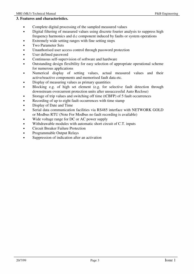


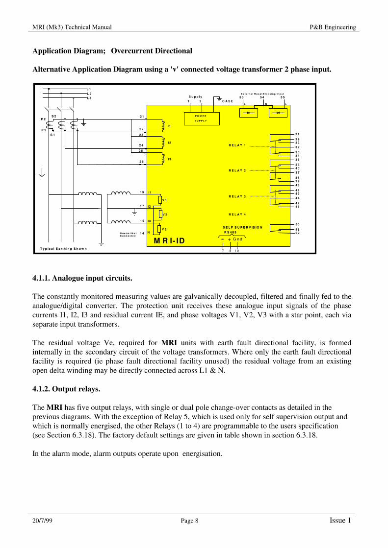
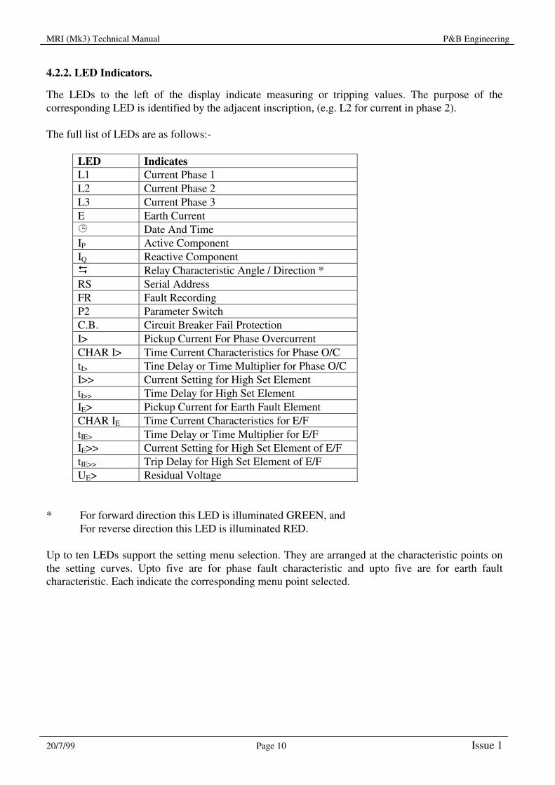
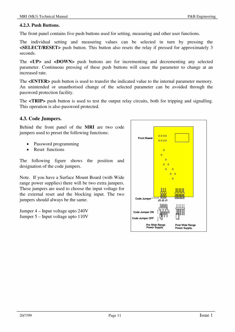
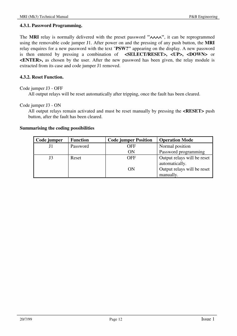


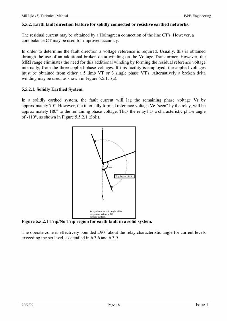
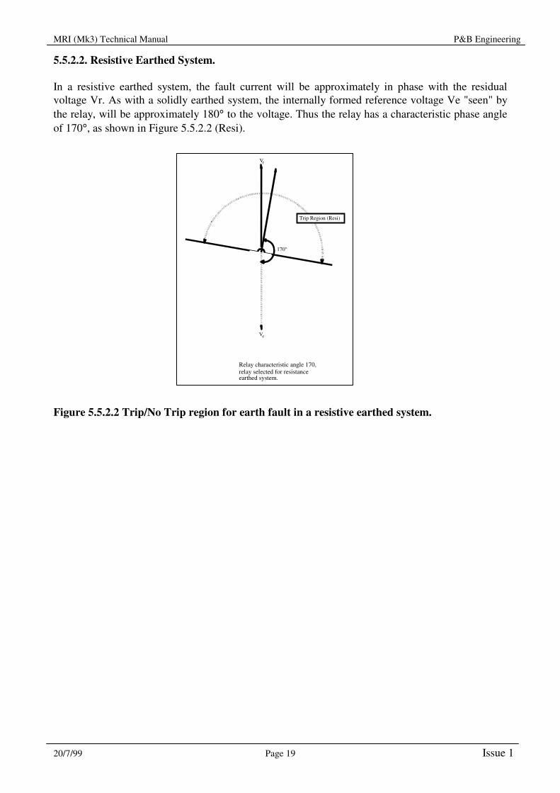

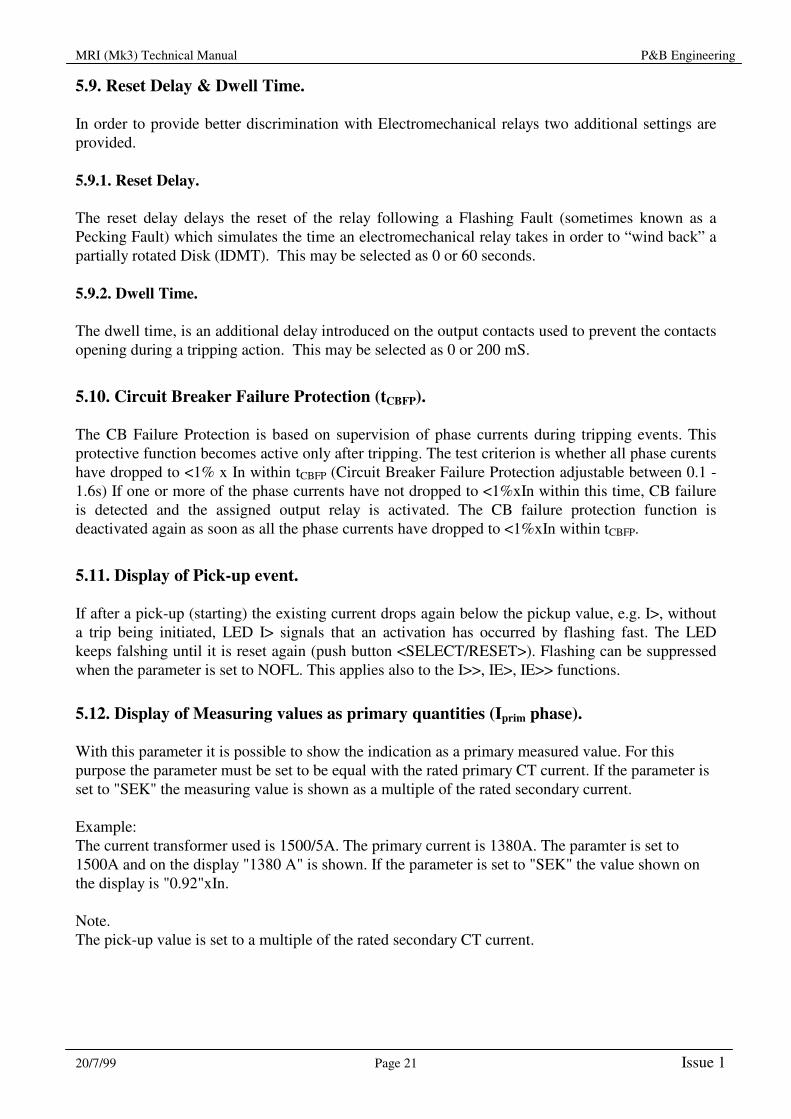


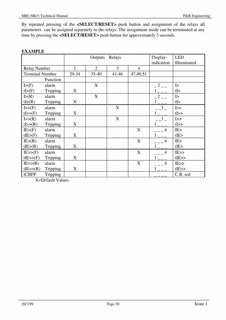


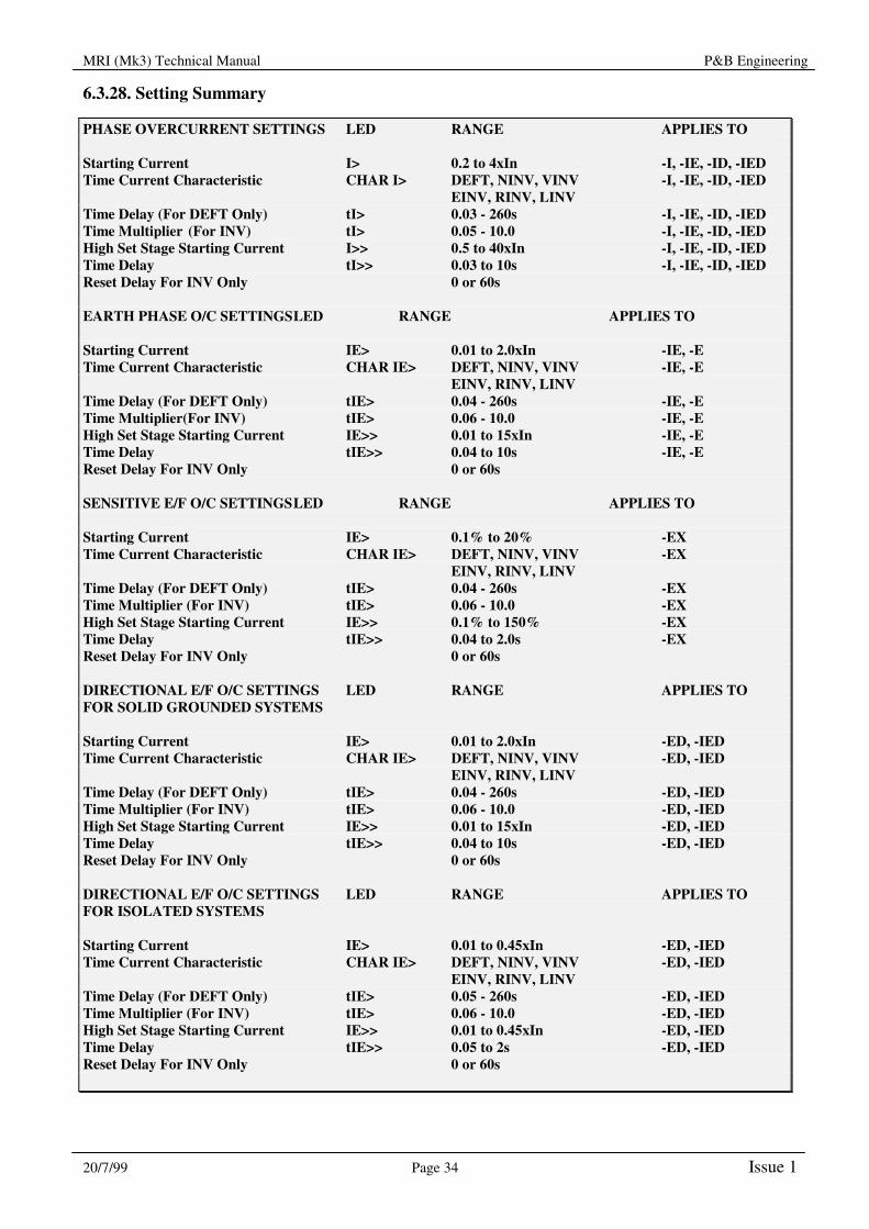
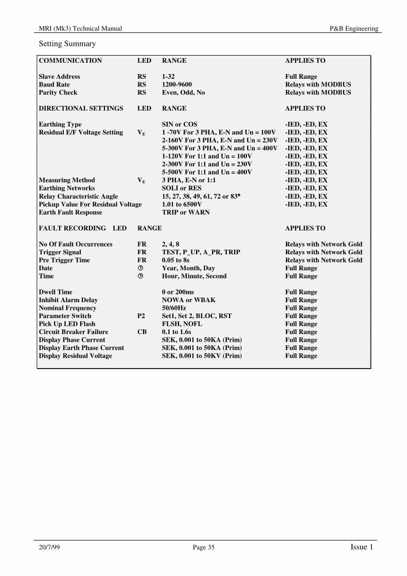
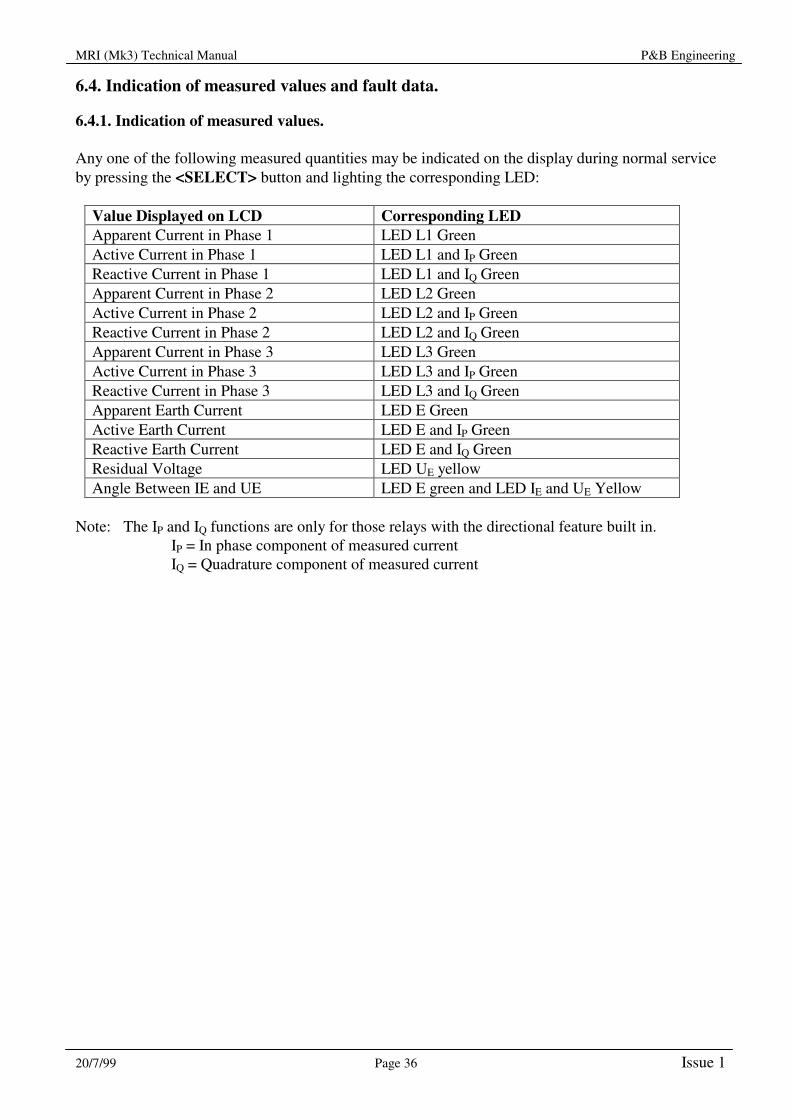
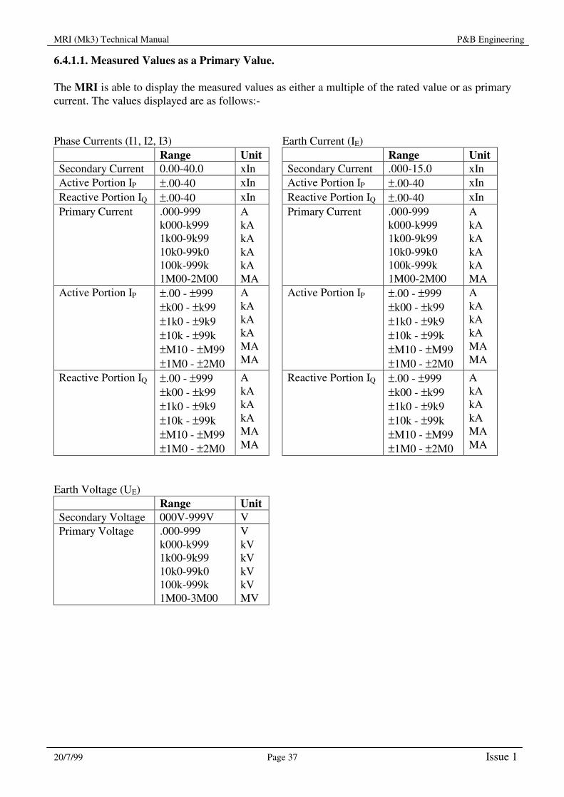

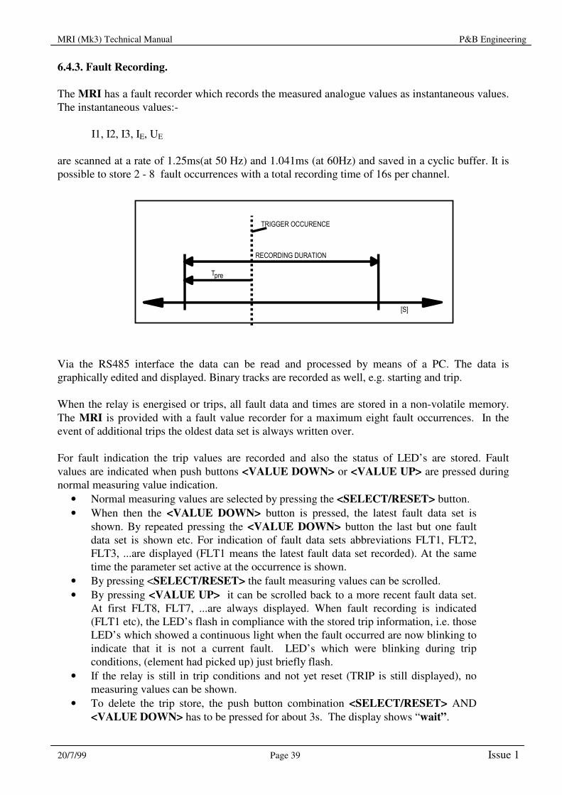
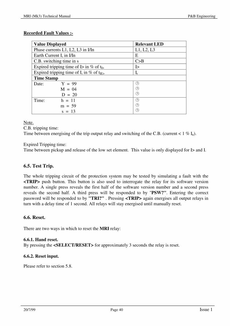

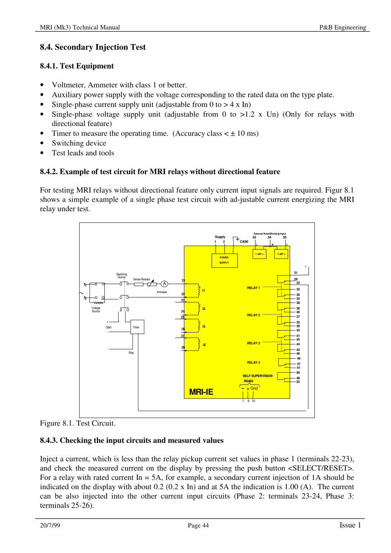

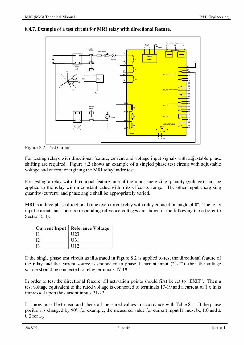
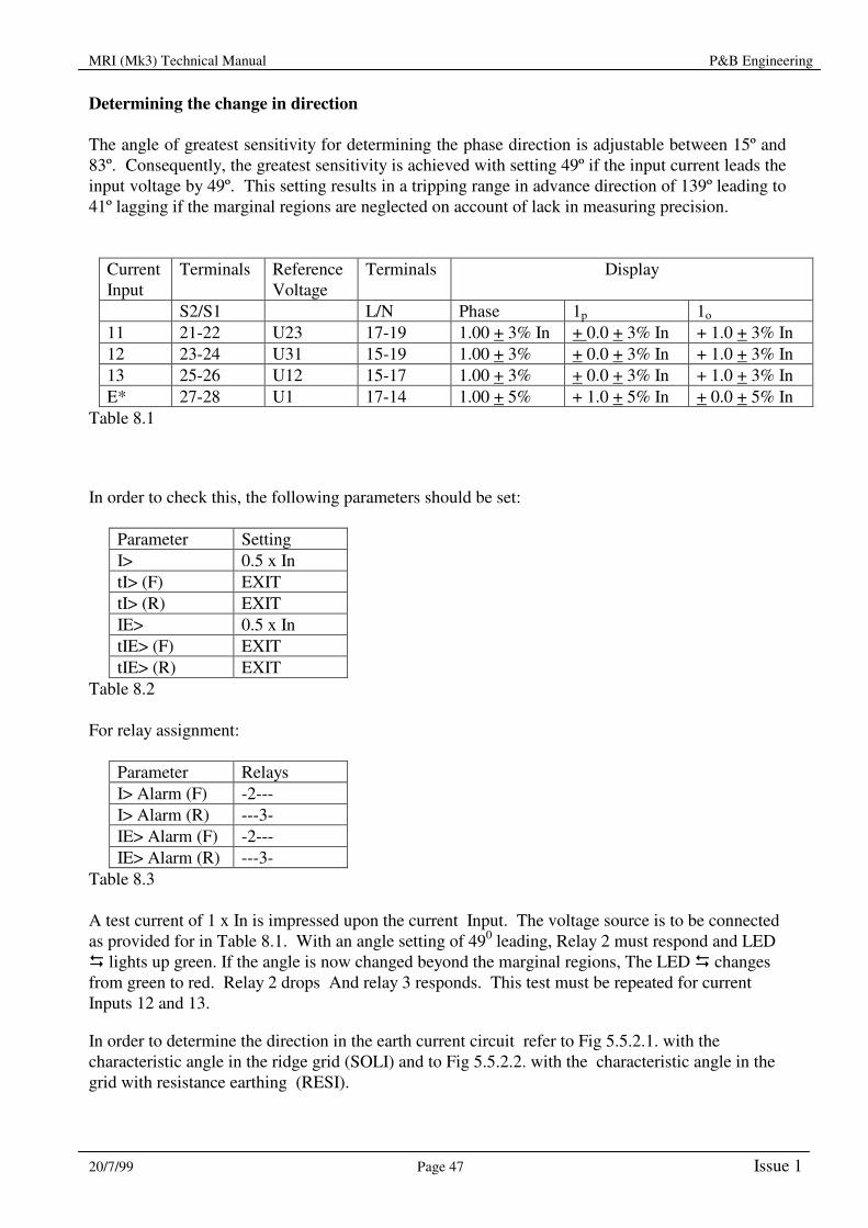


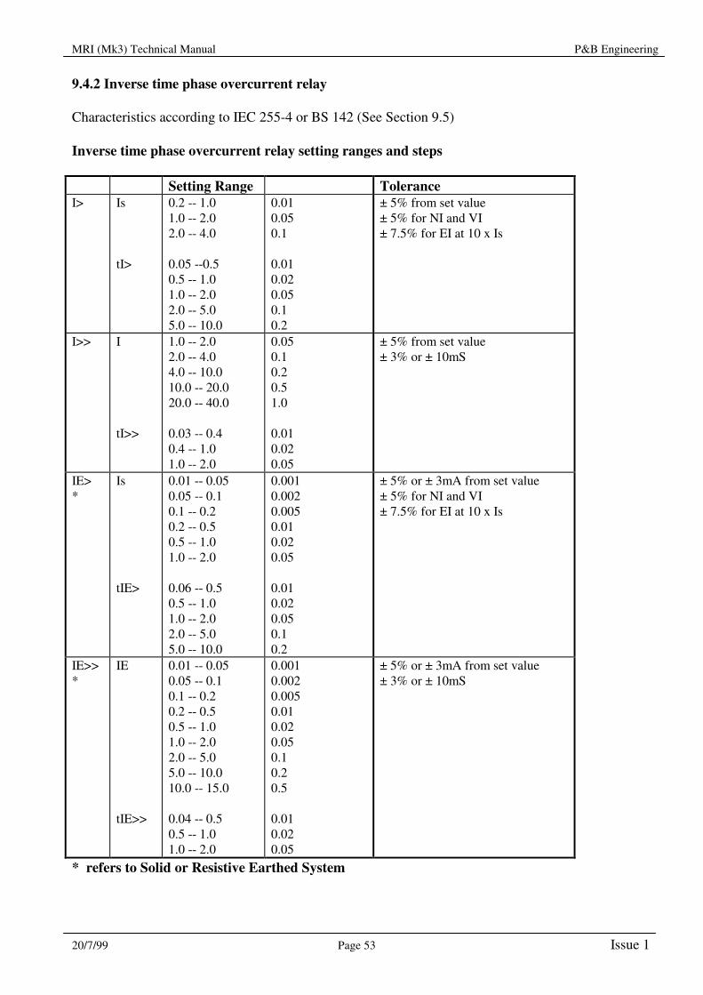

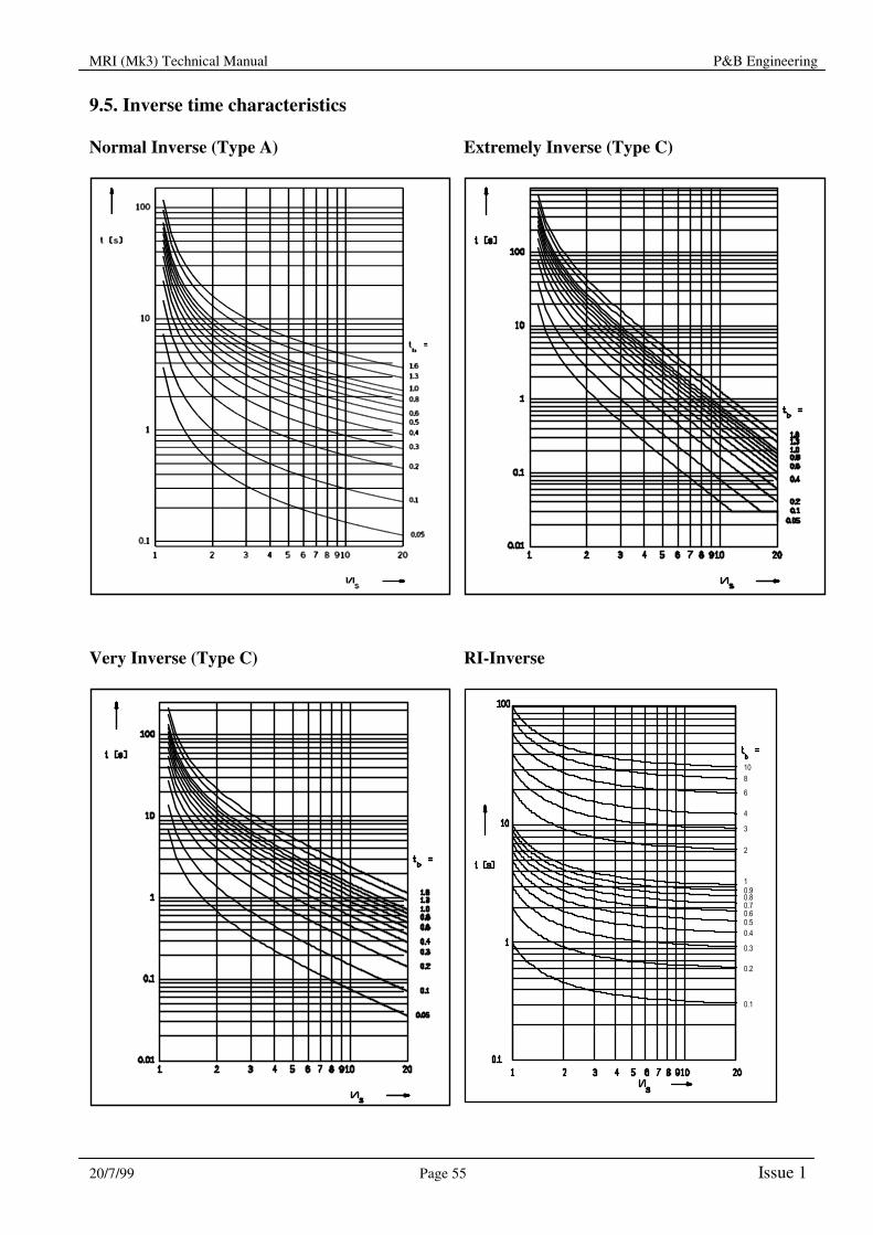

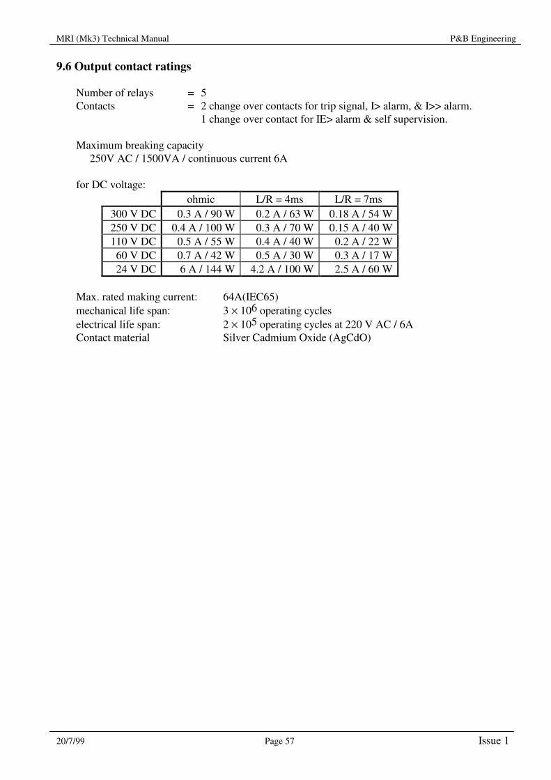
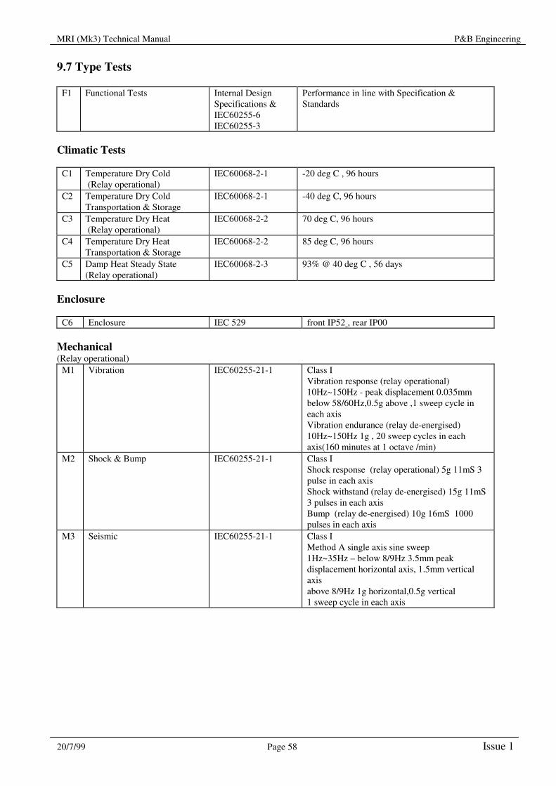

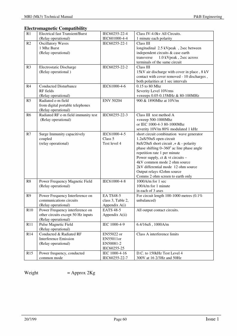
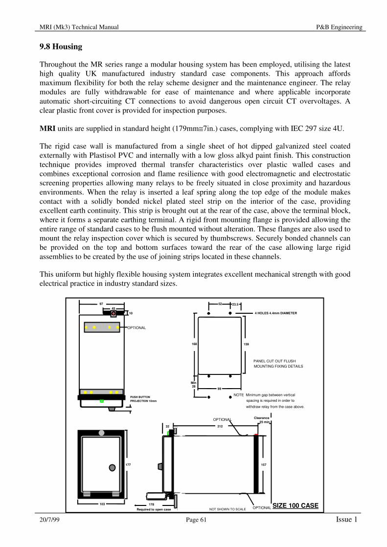
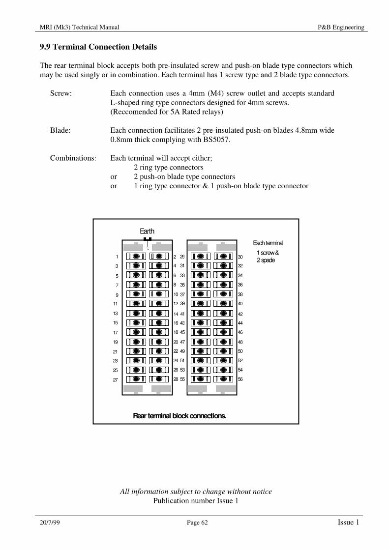


![Launchpad Mini [MK3]](https://static.documents.pub/doc/80x56/61bd4f1261276e740b117f87/launchpad-mini-mk3.jpg)

![Manuel MOTU Ultralite MK3 [Francais]](https://static.documents.pub/doc/80x56/55cf8de1550346703b8c3468/manuel-motu-ultralite-mk3-francais.jpg)