Abstract— This paper presents a novel actuation technology for robotically assisted MRI-guided interventional procedures. Compact and wireless, the actuators are both powered and controlled by the MRI scanner. The design concept and performance limits are described and derived analytically. Simulation and experiments in a clinical MR scanner are used to validate the analysis and to demonstrate the capability of the approach for needle biopsies. The concepts of actuator locking mechanisms and multi-axis control are also introduced.
I. INTRODUCTION
he importance of robotically-assisted MR-guided interventions is well recognized by the clinical and
research communities [1]. In these procedures, the robot provides precision, accuracy, speed and also offers the possibility for remote operation. The high quality images and the well-defined 3D coordinate system provided by MRI facilitate periodic updates to the planned trajectory of the robotic interventional tool and enable compensation for intraoperative organ and tissue deformations [2].
The development of MRI interventional robotic systems face several challenges related to compatibility and space constraints. The actuators must ensure MRI safety, preserve image quality, and be able to operate unaffected by the scanner’s electric and magnetic fields distortion [1]. Several groups worldwide have developed MR-compatible robotic systems [3-9]. These systems are usually specific to the prostate, breast or brain, and most perform the task of needle guidance for biopsies or interventional therapies.
Conventional actuation principles involving electromagnetic actuators are generally not MR-compatible. Therefore alternative actuation principles are employed, such as ultrasonic motors and pneumatic actuators. For example, the MR-compatible robots of [3-5] for needle-based interventions all employ ultrasonic motors. MR compatibility measurements demonstrated that when ultrasonic motors are placed inside the MRI bore and are powered on, there is large reduction in imaging SNR [6]. Consequently, actuation and imaging must be interleaved; making the implementation of real-time control more difficult [1]. Ultrasonic motors can be continuously operated only if they are placed at a distance from the bore, but flexibility, backlash and friction are introduced due to remote actuation of joints [5].
This work was supported by the National Institutes of Health under grant
R01HL073647. P. Vartholomeos and P. Dupont are with Cardiac Surgery, Children’s
Hospital Boston, Harvard Medical School, Boston, MA 02115 USA (panagiotis.vartholomeos|[email protected]).
L. Qin is with Radiology, Brigham and Women’s Hospital, Harvard Medical School, Boston, MA, 02115 USA. ([email protected]).
Pneumatic actuators, in contrast, do not cause SNR reduction, but they do require a complicated installation that involves locating a control unit, power supplies, amplifiers and valves externally to the MRI shielded room [7,8]. Furthermore, the pneumatic transmission lines lower the bandwidth and, in combination with the spatial constraints of the MRI bore, complicate robot design [9].
The contribution of this paper is to propose an actuator technology that is both powered and controlled by the MRI scanner. The principle of operation is based on one or more small ferromagnetic bodies embedded in the actuator that serve to convert the electromagnetic energy of the MR gradients into mechanical energy. The ferromagnetic bodies have a small volume and can be designed to be outside the imaging region of interest. Thus, they do not affect imaging quality. The actuators themselves are also wireless and compact. In addition, since the MR system provides both imaging and control of the interventional procedure using a common software interface, the integration of actuation and imaging is simplified.
The use of MRI gradients to induce motion to ferromagnetic particles in the vasculature has been previously performed [10,11,12]. For example, Martel et al. demonstrated closed-loop trajectory control of a 1.5 mm diameter ferromagnetic sphere in the carotid artery of a pig [10,11]. In these papers, the ferromagnetic particle is the robot. This work inspired us to think of ways to use the same force production principles to design actuators that could power more general interventional robots. The result is the actuator technology described here.
The remainder of the paper is organized as follows: Section II reviews the background theory on the generation of actuator forces by the MRI scanner. Section III describes the design of a prototypical actuator. Actuator dynamics are presented in Section IV and open-loop stability is also analyzed. Section V presents validation experiments performed in a clinical MRI. These experiments demonstrate the force production capabilities of the actuator. They also demonstrate the concept of an actuator locking mechanism to avoid accidental actuator motion as well as to enable independent control of multiple actuators. Conclusions appear in the final section of the paper.
II. BACKGROUND THEORY
When a ferromagnetic body is placed inside an MRI bore, it becomes magnetized due to the strong and uniform B0
central field directed along the axis of symmetry of the bore. The magnetization across the volume of the body can be
MRI-powered Actuators for Robotic Interventions
Panagiotis Vartholomeos, Member, IEEE, Lei Qin and Pierre E. Dupont, Fellow, IEEE
T
2011 IEEE/RSJ International Conference onIntelligent Robots and SystemsSeptember 25-30, 2011. San Francisco, CA, USA
approximated as a lumped effect at the center of mass (CM) of the body [13]. Consequently, the magnetized body is approximated by a magnetic dipole placed at its CM. For typical central field strengths, the magnetization magnitude asymptotically approaches the saturation magnetization value
Ms of the material, and its direction points along the easy
magnetization axis of the body, which depends on the shape anisotropy of the material. The magnetic torque and force acting on the body can be computed using the expressions for
the torque T and force F acting on a magnetic dipole in an
external field B = B0 + Bg :
T = VMs × B (1a)
F = nV (Ms ⋅∇)B (1b)
where Bg
is the magnetic field generated by the gradient
coils, V is the magnetic volume of the material, Ms is the
saturated magnetization per unit volume of the material, and n is the duty cycle fraction of the MRI gradients. The
magnetic torque T tends to rotate the ferromagnetic body so
that the magnetization vector Ms aligns with the direction of
the external B0 field (the contribution of the Bg field to the
torque T is negligible). Since the B0 field inside an MRI is
fixed and cannot be controlled by the user, the torque T is not a valuable quantity for control purposes.
The magnetic forces F depend on the spatial variation of
the field Bg , generated by the gradient coils. These comprise
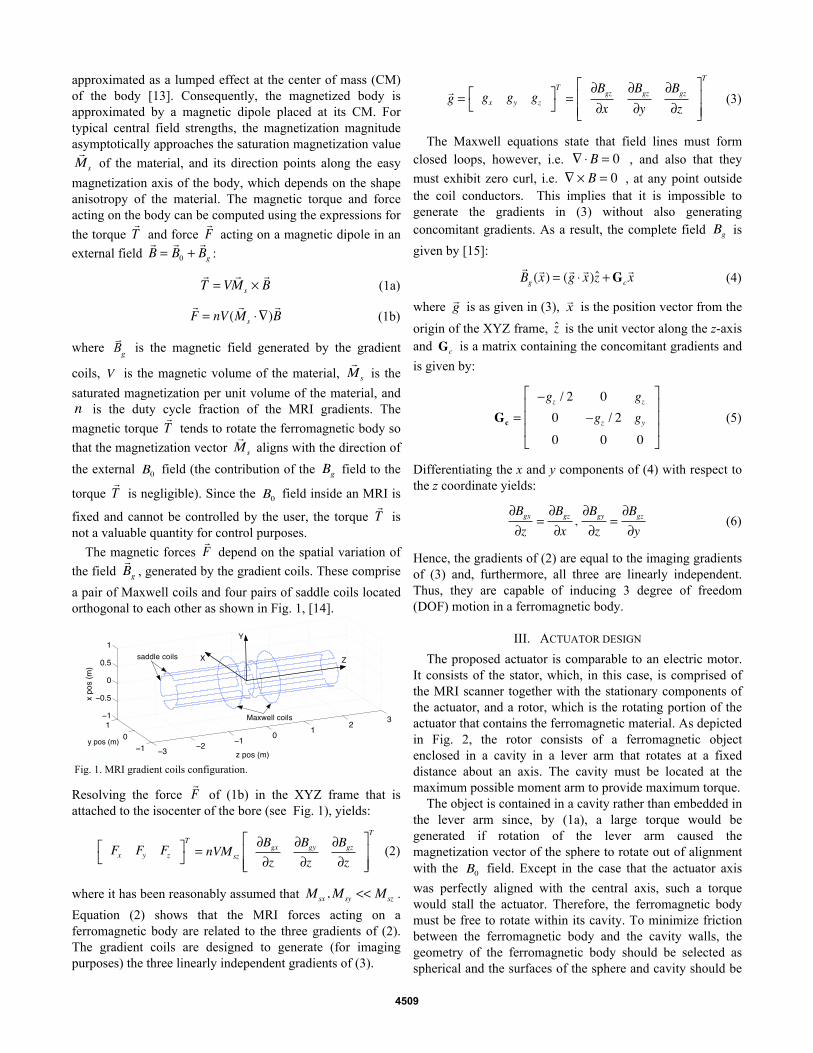
a pair of Maxwell coils and four pairs of saddle coils located orthogonal to each other as shown in Fig. 1, [14].
Fig. 1. MRI gradient coils configuration.
Resolving the force F of (1b) in the XYZ frame that is attached to the isocenter of the bore (see Fig. 1), yields:
Fx Fy Fz⎡⎣
⎤⎦T
= nVMsz
∂Bgx∂z
∂Bgy∂z
∂Bgz∂z
⎡
⎣⎢⎢
⎤
⎦⎥⎥
T
(2)
where it has been reasonably assumed that Msx ,Msy << Msz .
Equation (2) shows that the MRI forces acting on a ferromagnetic body are related to the three gradients of (2). The gradient coils are designed to generate (for imaging purposes) the three linearly independent gradients of (3).
g = gx gy gz⎡⎣
⎤⎦T
=∂Bgz∂x
∂Bgz∂y
∂Bgz∂z
⎡
⎣⎢⎢
⎤
⎦⎥⎥
T
(3)
The Maxwell equations state that field lines must form closed loops, however, i.e. ∇ ⋅ B = 0 , and also that they
must exhibit zero curl, i.e. ∇ × B = 0 , at any point outside the coil conductors. This implies that it is impossible to generate the gradients in (3) without also generating concomitant gradients. As a result, the complete field Bg is
given by [15]:
Bg (x) = (g ⋅ x)z +Gcx (4)
where g is as given in (3), x is the position vector from the
origin of the XYZ frame, z is the unit vector along the z-axis and Gc is a matrix containing the concomitant gradients and
is given by:
Gc =−gz / 2 0 gz0 −gz / 2 gy
0 0 0
⎡
⎣
⎢⎢⎢
⎤
⎦
⎥⎥⎥
(5)
Differentiating the x and y components of (4) with respect to the z coordinate yields:
∂Bgx∂z
=∂Bgz∂x
,∂Bgy∂z
=∂Bgz∂y
(6)
Hence, the gradients of (2) are equal to the imaging gradients of (3) and, furthermore, all three are linearly independent. Thus, they are capable of inducing 3 degree of freedom (DOF) motion in a ferromagnetic body.
III. ACTUATOR DESIGN
The proposed actuator is comparable to an electric motor. It consists of the stator, which, in this case, is comprised of the MRI scanner together with the stationary components of the actuator, and a rotor, which is the rotating portion of the actuator that contains the ferromagnetic material. As depicted in Fig. 2, the rotor consists of a ferromagnetic object enclosed in a cavity in a lever arm that rotates at a fixed distance about an axis. The cavity must be located at the maximum possible moment arm to provide maximum torque.
The object is contained in a cavity rather than embedded in the lever arm since, by (1a), a large torque would be generated if rotation of the lever arm caused the magnetization vector of the sphere to rotate out of alignment with the B0 field. Except in the case that the actuator axis
was perfectly aligned with the central axis, such a torque would stall the actuator. Therefore, the ferromagnetic body must be free to rotate within its cavity. To minimize friction between the ferromagnetic body and the cavity walls, the geometry of the ferromagnetic body should be selected as spherical and the surfaces of the sphere and cavity should be
4509
designed to minimize friction.
Fig. 2. Actuator schematic. (a) Complete assembly. (b) Detail of spherical cavity and encapsulated magnetic sphere aligned to the field B0.
All actuator components are nonferrous apart from the embedded ferromagnetic body. The preferred ferromagnetic material is chrome steel because it has the second highest saturation magnetization among the ferromagnetic materials ( ~ 1.4 ⋅106Am−1 ), it can very easily be machined into spherical shape and its surface has very low roughness [16].
Rotation of the actuator is generated by applying magnetic field gradients to generate a force F on the ferromagnetic sphere as shown in Fig. 2. Assuming for simplicity that the xyz frame of the actuator coincides with the XYZ frame of the isocenter of the MRI bore (Fig. 1), gravity is directed along the y axis and so does not affect rotor motion.
From the free-body diagram of Fig. 3, the single degree of freedom motion is described by the following scalar equation
Jθ = −bθ + r1F sin(φ −θ ) (7)
in which J is the moment of inertia of the composite body that comprises the axis, the lever and the sphere, r1 is as
shown in Fig. 3, b is the coefficient of viscous friction, and θ is the angle of the rotor, and φ is the angle of the
magnetic gradient.
Fig. 3. Force F acts on the sphere and the lever rotates about y-axis.
The angle θ is called the mechanical angle, and the angle φ
is called the magnetic angle. Their difference is called the slip angle, s :
s = φ −θ (8)
and is a critical parameter for the analysis of the motor. F and φ are given by:
F = F = Fx
2 + Fz2 , φ = tan−1(Fx / Fz ) (9)
where Fx ,Fz are as given in Eq. (2).
The maximum allowable gradient of a clinical MRI is 40
mT/m, which results in a small magnetic force F (on the order of tens of mN for magnetic volumes of a few mm3). This limitation can be addressed using transmission elements to provide interventional-level forces. Candidate solutions include gear trains, screws and harmonic drives.
The experimental actuator presented later in the paper employs gears together with a rack and pinion to produce linear motion, as illustrated schematically in Fig. 4. The pinion N1 is keyed to the lever and transmits the lever
motion to the rest of the transmission elements, which consist of three gears, three pinions, and one rack. All rotations as well as the rack translation take place on the x-z plane.
Fig. 4. Transmission unit incorporating gear train and rack and pinion elements.
The reduction ratio between θ and the rack speed ur is:
R = ur
θ= r2G1G2G3
(10)
The G1,G2 ,G3 are transmission ratios given by:
G1 = N2 / N1, G2 = N4 / N3, G3 = N6 / N5 (11)
while Ni , {i = 1, .., 6} are the gear teeth, and r2 is the radius
of the N7 pinion.
To maximize output force, the x-y plane of the rotor has to coincide with the X-Z plane of the MRI bore. Otherwise, part of the magnetic force is used for compensating gravity. If the output force has to be applied at an angle with respect to the x-y plane, then bevel gears can be used to change the axis of rotation.
IV. DYNAMIC MODEL AND STABILITY ANALYSIS
The performance characteristics of the proposed actuator technology can be determined from an analysis of the governing dynamic equations. The analysis focuses on the rotor characteristics, since the stator, i.e. the MRI scanner, cannot be modified. To this end, (9) is extended to incorporate the transmission as well as terms for non-viscous friction and load:
Jdθdt
= −Bθ − Tfr − RFl + r1F sin(φ −θ ) (12a)
ur = Rθ (12b)
����������� �
���� ��������
4510
Here, R and ur are defined in (10). The terms J and B are
the summation of the inertia and viscous friction terms, respectively, of all transmission stages as seen by the input of the system. The term Tfr is the summation of all non-viscous
friction terms as seen by the input including the friction component contributed by the ferromagnetic sphere when it slides inside the cavity. The non-viscous friction terms are modeled as constants and Fl is the load applied on the tip of
the rack. It is reasonably assumed that the eddy currents induced on the millimeter-scale chrome steel sphere are very small and can be neglected [17].
A. Actuator performance with closed-loop control of slip angle
Closed-loop actuator control requires using the MRI scanner to both measure the actuator state and to apply the actuation force. While this approach does require sophisticated and nonstandard MRI programming, it has been previously demonstrated for the navigation of spherical particles in the vasculature [11].
In a typical robotic intervention, the robot’s actuators would be operated in a position or velocity control loop so as to drive the tool, e.g., biopsy needle, to a desired location. In such an application, an inner control loop can be implemented for each actuator that regulates its slip angle to s = π / 2 so as to maximize the force or torque that can be generated by the actuator. The steady-state output linear velocity ur is given by:
ur = − R2
Br2Fl + R(
r1F
B−Tfr
B)
= − R2
Br2Fl + R(
r1VMsBgradB
−Tfr
B)
(13)
where
Bgrad = ((∂Bgx / ∂z)
2 + (∂Bgy / ∂z)2 )1/2 (14)
is constant. Eq. (13) reveals that when the slip angle is regulated at a constant value, then the output velocity ur is
linearly related to the output force Fl through a negative
proportionality constant. The maximum permissible output load (stall or blocking
force) is obtained for ur = 0 ms−1
and is given by:
Fl _max = (r1VMsBgrad − Tfr ) / R (15)
The mechanism is not able to generate output forces greater than Fl _max . Setting the output force Fl to zero yields the
maximum output velocity ur _max . This maximum output
velocity corresponds to a maximum rotational velocity of the
lever θmax = ur _max / R , which in turn gives the maximum
gradient frequency ωmax for a given Bgrad :
ωmax =r1VMsBgrad
B−Tfr
B (16)
The mechanism is not able to respond to a gradient rotating at frequencies greater than ωmax .
B. Actuator performance without control of slip angle The preceding subsection proposed a nested control
structure in which an inner control loop regulates slip angle and an outer loop controls actuator position or velocity. This subsection addresses the simpler case in which slip angle is not controlled. To understand if this approach may suffice for simple interventional applications, this subsection studies the stability of two important cases. The first is when a constant load is applied to the actuator and it is driven at constant velocity. The second case corresponds to a linear elastic load driven at constant velocity. This latter case is comparable to the loading experienced by a biopsy needle pressing against tissue prior to puncture.
1) Constant-velocity constant-load stability In this case, the MRI scanner is programmed to generate
gradients rotating in the X-Z plane at constant frequencyω . The gradients are given by:
∂Bgx∂z
∂Bgz∂z
⎡
⎣⎢⎢
⎤
⎦⎥⎥
T
= Bgrad cosωt sinωt⎡⎣ ⎤⎦T
(17)
In the open loop case, stable operation of the actuator implies the rotor synchronizes with the rotating gradient frequency. To analyze the steady-state behavior of the system in response to the gradients of (17), (12a) is rewritten in state-space form as
where the slip angle s is considered a system output and is a linear function of the state x1 and the input u = ωt . The
equilibrium point is found by setting x1 = ω , x2 = 0 , and is
x*1 = ωt − s* (19a)
x*2 = ω (19b)
s* = sin−1((Bω + Tfr + RFl ) / (r1F)) (19c)
where s* is the equilibrium slip angle. The stability of the system of (18) in the vicinity of the equilibrium point is
determined via linearization with respect to the (x*1, x*2 )
point. To this end, the system of (18) is rewritten as:
e1 = e2
e2 = − BJe2 + (
Bω + Tfr + RFlJ
− r1FJsin(e1 + s))
(20)
4511
where
e1e2
⎡
⎣⎢
⎤
⎦⎥ =
x1* − x1x2* − x2
⎡
⎣⎢⎢
⎤
⎦⎥⎥
(21)
The linearization is evaluated at:
e = [ e1 e2 ]T = [ 0 0 ]T (22)
and the linear state equations in vector form are given by e = Ae , where A is the system matrix:
A =0 1
−(Fr1 / J ) cos s* −B / J
⎡
⎣⎢⎢
⎤
⎦⎥⎥
(23)
Stability analysis of A shows that the equilibrium point
e* = [ 0 0 ]T is: (1) a stable focus for s* < π / 2 , (2) a
saddle point for s* = {−π / 2,π / 2} and (3) an unstable focus
for s* > π / 2 .
Referring back to Fig. 3, what this analysis shows is that mechanical angle lags magnetic angle. By (19c), the amount
of lag, s* , increases monotonically from zero as a function of gradient frequency ω , static friction Tfr and load Fl . Since
stability requires that s* < π / 2 , and magnetic torque is
maximized at s = π / 2 , constant-velocity constant-load
performance is reduced compared to the case where the slip angle s is controlled.
2) Constant-velocity elastic-load stability In biopsy applications, large forces are typically required
to puncture tissue layers, however, the load applied to the needle prior to puncture is not constant, but rather is viscoelastic. As an approximation to the viscoelastic tissue deformation force prior to puncture, this subsection considers the effect of an elastic load on the stability of the actuator during constant velocity operation.
In this case, the MRI gradients are as given in (17). The actuator rotor synchronizes with the constant gradient frequency and the rack pushes at a constant speed against the elastic material. The load force is given by:
Fl = kl⇒ Fl = kRθ (24)
where k is the tissue stiffness constant, and l is the deformation of the elastic load. Equation (18) is rewritten as:
Repeating the stability analysis of Eqs. (20-23) now yields the system matrix A as:
A =0 1
−(kR2 + Fr1 cos s* ) / J −B / J
⎡
⎣⎢⎢
⎤
⎦⎥⎥
(27)
The term kR2 is three to five orders of magnitude smaller
than Fr1 and can be neglected. Consequently, e* is again: (1)
a stable focus for s* < π / 2 , (2) a saddle point for,
s* = {−π / 2,π / 2} and (3) an unstable focus for s* > π / 2 .
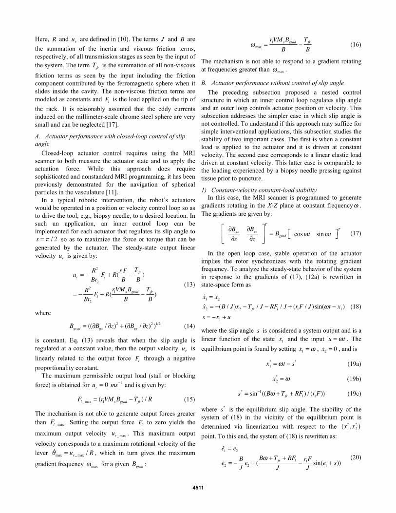
Simulation was performed to examine how the steady-state speed of the mechanism, the output force, and the slip angle vary for increasing load. In this section only qualitative results are of interest, therefore gross estimates of the parameter values were used for the simulations. Example plots appear in Fig. 5. As shown, for approximately 20 seconds, the velocity remains constant as the elastic load deforms. At the same time, the increase in elastic deformation is compensated by a proportional increase in the slip angle (i.e. increase of the input magnetic force F ).
This steady-state operation is maintained until the slip angle approaches π / 2 , at which point the actuator becomes unstable and begins to oscillate about a fixed position and zero velocity. Although the rotary oscillations of the lever are large, the transmitted oscillations to the output stage (the rack) are attenuated by the transmission ratio and so the output force exhibits small-amplitude oscillations about the value of the blocking force.
The blocking force is the maximum force that can be applied by the actuator on a load and is equal to Fl _max
derived in the case of the controlled slip angle. Hence, when the actuator is pushing against an elastic material it can exert the stall force Fl _max even without controlling the slip angle,
albeit with small oscillations.
Fig. 5. Simulation of constant-velocity elastic load response.
4512
V. ACTUATOR CHARACTERIZATION EXPERIMENTS
An actuator prototype was constructed using Lego components as shown in Fig. 6. Lego components offer a fast, easy and reliable way to build mechanisms that are MRI compatible. All components are plastic except for the bevel-type 21-gauge needle, which is made of (non-ferromagnetic) aluminum and the (ferromagnetic) chrome steel sphere. The dimensions of this prototype are 10x6x6 cm.
The experiments were performed in a clinical GE 1.5 T MRI scanner (Milwaukee, WI). The control sequences were programmed using the EPIC API. Important parameters of the mechanisms are presented in Table 1.
Fig. 6. Actuator with attached biopsy needle.
TABLE 1. ACTUATOR PARAMETERS
Parameter Value
Sphere radius [mm] 2.5
Sphere magnetization [Am-1] 1.36 106
Transmission ratio R [-] 3.2 10-5
Moment arm r1 [mm] 18
Magnetic gradient [mTm-1] 40
Duty cycle of MRI gradient coils [%] 100
Three sets of experiments were conducted in order to
validate the actuator concept and analysis. In all experiments, slip angle was uncontrolled. The first set of experiments was designed to estimate the viscous and non-viscous friction terms of the model. With these quantities, the performance under closed-loop control of slip angle can be characterized. The second set of experiments demonstrate tissue puncture on a porcine heart and also evaluate the ability to perform MRI tissue imaging in the presence of the actuator. The third and final set of experiments demonstrates an MRI-controlled locking mechanism.
A. MRI experiment 1: Estimation of friction terms To estimate actuator friction, the actuator was loaded
against a set of calibrated MR-compatible springs fabricated using NiTi wire. The springs were calibrated using standard weights. The four springs were housed in a Lego assembly as shown in Fig. 7. The spring assembly and the actuator were
mounted on a common Plexiglas base and placed at the isocenter of the scanner. Experiments were performed at four different gradient frequencies ω={1.25,1.45,1.6,2} Hz, and
the blocking force was computed from the maximum spring deflection as the actuator followed a trajectory comparable to that of Fig. 5.
Fig. 7a. Calibrated spring set for measuring forces applied to contact surface.
Fig. 7b. Actuator rack tip applies forces to contact surface of spring set.
The results of the four measurements are plotted in Fig. 8. The linear interpolation model is given by:
Fl = −0.4ω +1.3 (28)
Fig. 8. Blocking force data and linear fit.
Comparing (28) to (26c) for slip angle s = π / 2 rad (blocking force condition), the parameters of viscous friction and non-viscous friction are estimated to be:
B = 1.3 ⋅10−5Nsm-1, Tfr = 2.3 ⋅10−5mN (29)
Now that all parameter values are known, (13) is used to plot in Fig. 9 the relationship between output force Fl and
gradient frequency ω , for three different values of Bgrad .
Fig. 10 plots output power versus output linear speed. Note the similarity between these plots and those of DC motors.
Fig. 9. Output load versus gradient frequency.
Fig. 10. Output mechanical power versus output velocity.
B. MRI experiment 2: Porcine heart puncture This experiment demonstrates an interventional
1.3 1.4 1.5 1.6 1.7 1.8 1.9 2
0.5
0.55
0.6
0.65
0.7
0.75
0.8
Frequency (Hz)
For
ce (
N)
y vs. xlinear fit
4513
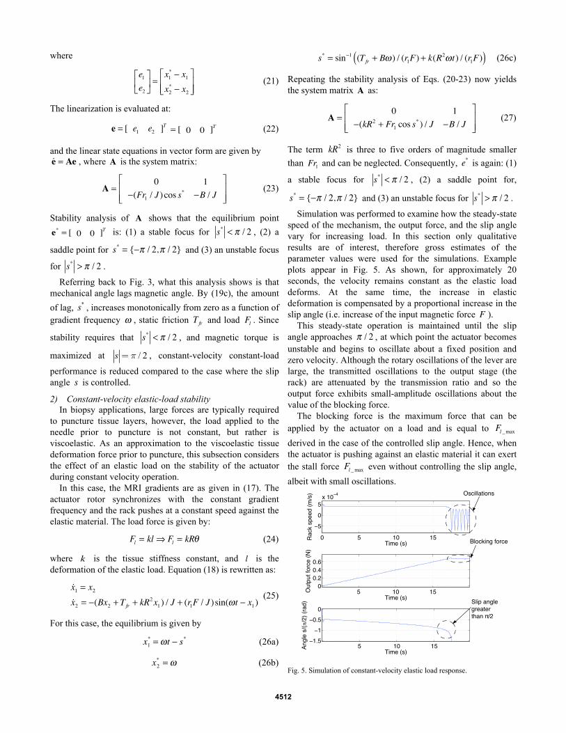
application of the prototype actuator. For these trials, a 21-gauge bevel-tip biopsy needle was attached to the tip of the rack and a swine heart was placed adjacent to the needle tip. Both the heart and the actuator were secured to a Plexiglas base as shown in Fig. 11 and located at the isocenter. Gradient field strengths of 20mT/m and 40mT/m were applied with a rotational frequency of 1Hz.
At 20mT/m, the needle failed to puncture the tough, elastic epicardial layer of the heart. At 40mT/m, the needle successfully punctured the epicardial layer and continued to penetrate the softer underlying myocardium to a depth of approximately 15mm. At this point, the actuator was commanded to reverse direction and was successfully withdrawn from the heart. These results are in agreement with the plots of Fig. 9 since it is known that the maximum epicardial puncture forces for swine hearts at a velocity of 1mm/s, lie in the range of 0.5N to 0.9N [18]. According to Fig. 9, these force requirements are provided by the 40 mT/m input, but not by the 20 mT/m. This experiment appears as an attached video file.
To evaluate the effect of the actuator on tissue imaging, standard imaging sequences were employed to image the biopsy needle inside the heart. While not depicted, it was determined that the SNR signal in the region of interest was unaffected by the ferromagnetic material of the actuator.
Fig. 11. Swine heart puncture experiment.
C. MRI experiment 3: Locking mechanism Most robotic applications involve controlling multiple
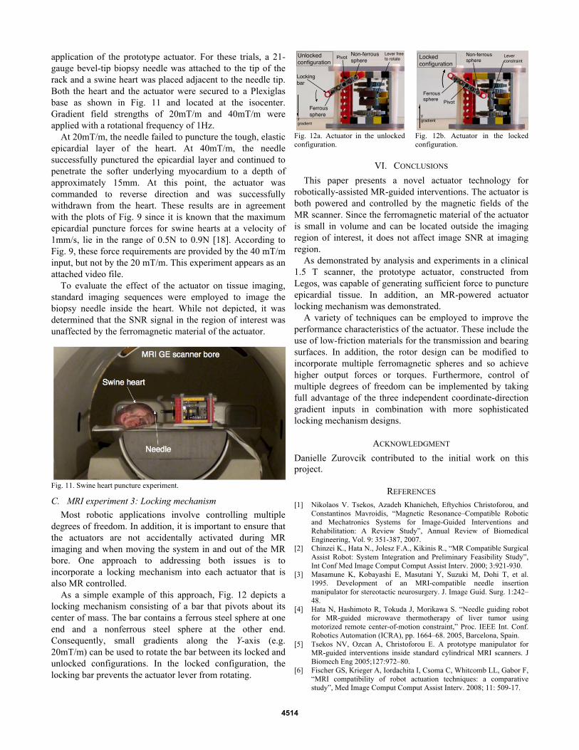
degrees of freedom. In addition, it is important to ensure that the actuators are not accidentally activated during MR imaging and when moving the system in and out of the MR bore. One approach to addressing both issues is to incorporate a locking mechanism into each actuator that is also MR controlled.
As a simple example of this approach, Fig. 12 depicts a locking mechanism consisting of a bar that pivots about its center of mass. The bar contains a ferrous steel sphere at one end and a nonferrous steel sphere at the other end. Consequently, small gradients along the Y-axis (e.g. 20mT/m) can be used to rotate the bar between its locked and unlocked configurations. In the locked configuration, the locking bar prevents the actuator lever from rotating.
Fig. 12a. Actuator in the unlocked configuration.
Fig. 12b. Actuator in the locked configuration.
VI. CONCLUSIONS
This paper presents a novel actuator technology for robotically-assisted MR-guided interventions. The actuator is both powered and controlled by the magnetic fields of the MR scanner. Since the ferromagnetic material of the actuator is small in volume and can be located outside the imaging region of interest, it does not affect image SNR at imaging region.
As demonstrated by analysis and experiments in a clinical 1.5 T scanner, the prototype actuator, constructed from Legos, was capable of generating sufficient force to puncture epicardial tissue. In addition, an MR-powered actuator locking mechanism was demonstrated.
A variety of techniques can be employed to improve the performance characteristics of the actuator. These include the use of low-friction materials for the transmission and bearing surfaces. In addition, the rotor design can be modified to incorporate multiple ferromagnetic spheres and so achieve higher output forces or torques. Furthermore, control of multiple degrees of freedom can be implemented by taking full advantage of the three independent coordinate-direction gradient inputs in combination with more sophisticated locking mechanism designs.
ACKNOWLEDGMENT
Danielle Zurovcik contributed to the initial work on this project.
REFERENCES [1] Nikolaos V. Tsekos, Azadeh Khanicheh, Eftychios Christoforou, and
Constantinos Mavroidis, “Magnetic Resonance–Compatible Robotic and Mechatronics Systems for Image-Guided Interventions and Rehabilitation: A Review Study”, Annual Review of Biomedical Engineering, Vol. 9: 351-387, 2007.
[2] Chinzei K., Hata N., Jolesz F.A., Kikinis R., “MR Compatible Surgical Assist Robot: System Integration and Preliminary Feasibility Study”, Int Conf Med Image Comput Comput Assist Interv. 2000; 3:921-930.
[3] Masamune K, Kobayashi E, Masutani Y, Suzuki M, Dohi T, et al. 1995. Development of an MRI-compatible needle insertion manipulator for stereotactic neurosurgery. J. Image Guid. Surg. 1:242–48.
[4] Hata N, Hashimoto R, Tokuda J, Morikawa S. “Needle guiding robot for MR-guided microwave thermotherapy of liver tumor using motorized remote center-of-motion constraint,” Proc. IEEE Int. Conf. Robotics Automation (ICRA), pp. 1664–68. 2005, Barcelona, Spain.
[5] Tsekos NV, Ozcan A, Christoforou E. A prototype manipulator for MR-guided interventions inside standard cylindrical MRI scanners. J Biomech Eng 2005;127:972–80.
[6] Fischer GS, Krieger A, Iordachita I, Csoma C, Whitcomb LL, Gabor F, “MRI compatibility of robot actuation techniques: a comparative study”, Med Image Comput Comput Assist Interv. 2008; 11: 509-17.
4514
[7] Kapoor, A. Wood, B. Mazilu, D. Horvath, K.A. Ming Li, “MRI-compatible hands-on cooperative control of a pneumatically actuated robot ”, Proc. IEEE Int. Conf. Robotics and Automation (ICRA), pp. 2681 – 2686, 12-17 May 2009.
[8] Patriciu, A., Petrisor, D., Muntener, M., Mazilu, D., Schar, M., Stoianovici, D., “Automatic Brachytherapy Seed Placement Under MRI Guidance”, IEEE Transactions on Biomedical Engineering, Aug. 2007, Vol 54 (8), p. 1499 – 1506.
[9] Sang-Eun Song; Cho, N.B.; Fischer, G.; Hata, N.; Tempany, C.; Fichtinger, G.; Iordachita, I. , “Development of a Pneumatic Robot for MRI-guided Transperineal Prostate Biopsy and Brachytherapy: New approaches”, Proc. IEEE Conf. Robotics and Automation (ICRA), pp. 2580 – 2585, 2010, Anchorage, Alaska USA.
[10] Martel S., Felfoul O., Mathieu J-B., Chanu A., Tamaz S., Mohammadi M., Mankiewicz M., and Tabatabaei N., “MRI-based nanorobotic platform for the control of magnetic nanoparticles and flagellated bacteria for target interventions in human capillaries,” International Journal of Robotics Research (IJRR), Special Issue on Medical Robotics, vol. 28, no. 9, pp. 1169-1182, Aug. 2009.
[11] Martel S., Mathieu J.-B., Felfoul O., Chanu A., Aboussouan É., Tamaz S., Pouponneau P., Beaudoin G., Soulez G., Yahia L'H., and Mankiewicz M., “Automatic navigation of an untethered device in the artery of a living animal using a conventional clinical magnetic resonance imaging system”, Applied Physics Letters, vol. 90, no. 11, 114105 (3 pages), March 12, 2007.
[12] Arcese, L. Fruchard, M. Ferreira, A., “Nonlinear modeling and robust controller-observer for a magnetic microrobot in a fluidic environment using MRI gradients”, Proceedings of the 2009 IEEE/RSJ international conference on Intelligent robots and Systems (IROS), St. Louis, Missouri, USA, pp. 534 – 539.
[13] Abbott, J.J., Ergeneman, O., Kummer, M.P., Hirt, A.M., Nelson, B.J., “Modeling Magnetic Torque and Force for Controlled Manipulation of Soft-Magnetic Bodies”, IEEE Transactions on Robotics, Vol. 23, No. 6, Dec. 2007, Vol. 23, (6), pp. 1247 - 1252.
[14] Jianming Jin, Electromagnetic Analysis and Design in Magnetic Resonance Imaging, 1999, CRC Press, Boca Raton, FL.
[15] B. H. Han, S. Park and S. Y. Lee, “Gradient waveform synthesis for magnetic propulsion using MRI gradient coils”, Physics in Medicine and Biology, Volume 53, Number 17, pp. 4639.
[16] http://www.gobearings.com/materials.htm [17] Giffin, A., Shneider, M., Chiranjeev K., S., Ames, T L; Miles, R. B,
“Effects of a Conducting Sphere Moving Through a Gradient Magnetic Field”, AIAA Aerospace Sciences Meeting, Orlando, Florida, Jan 4-7, 2010.
[18] Mahvash M., P. Dupont, “Mechanics of Dynamic Needle Insertion into a Biological Material”, IEEE Transactions of Biomedical Engineering, Vol, 57, No 4., 934-43, April 2010.