36
T E C H N I C A L C A T A L O G MS02 - MSE02 HYDRAULIC MOTORS new generation
T E C H N I C A L C A T A L O G
MS02 - MSE02HYDRAULIC MOTORS
new generation

2 24/01/2011
Hydraulic motors MS02 - MSE02 new generation POCLAIN HYDRAULICS
CHARACTERISTICS
Motor inertia = 0.01 kg.m²Noise emissions = 60 dBA
8 172 [10,5] 86 [5,2] 273 [139] 590* 580* 590*
0 213 [13,0] 107 [6,5] 339 [172] 470* 470* 475*
1 235 [14,3] 118 [7,2] 374 [190] 430* 425* 430*
2 255 [15,6] 128 [7,8] 405 [206] 395* 390* 395*
0 332 [20,2] 166 [10,1] 528 [268] 265* 325* 340*
1 364 [22,2] 182 [11,1] 579 [294] 245* 300* 310*
2 398 [24,3] 199 [12,1] 633 [322] 225* 270* 285*
86 [5,2]
128 [7,8]
85 [5,2]
107 [6,5]
133 [8,1]
199 [12,1]
450 [6 527]
[5 802]
450 [6 527]
400 [5 802]22 [30]
285* 400
-
-
-
16,5 [22]
12
N
A
213 [13,0]
192
332
[11,7]
[20,2]
A [172]339
18 [24]
395*
475*[155]
[268]
305
528 22 [30]
18 [24]
[16]
16,5 [22]
9
11
12 [16] [12]
11 [15]
9 [12]
[15]
390*
470*
270*
Cam
s w
ith e
qual
lobe
sC
ams
with
une
qual
lobe
s
MS0
2M
SE02
MS0
2M
SE02
Pression max.
bar [PSI]
Max.power
kW [HP]cm³/tr [cu.in/rev.]cm³/tr [cu.in/rev.]preferredkW [HP]
non-preferredkW [HP]
First displacement
Second displacement
* See option ’’M’’ for higher speed or lower charge pressure.
Max.speed
tr/min [RPM]tr/min[RPM]
Theoretical torque
at �P 100 bar at �P 1000 PSI
Nm [lb.ft]
For a charge pressure of20 bar [290 PSI]

24/01/2011 3
CONTENT
POCLAIN HYDRAULICS Hydraulic motors MS02 - MSE02 new generation
Hyd
roba
ses
Bra
keSh
aft m
otor
sO
ptio
nsW
heel
mot
ors
Inst
alla
tion
Valv
ing
syst
ems
Mod
el c
ode
Mod
ular
ity
MODULARITY 4
MODEL CODE 6
WHEEL MOTOR 9
Dimensions for standard 1-displacement motor 9Dimensions for standard 2-displacements motor 9Dimensions for standard Twin-Lock™ motor 10Dimensions for standard motor with exchange 10Studs 11Support types 11Radial load and service life of bearings curves 12
SHAFT MOTOR 13
Dimensions for standard 1-displacement motor 13Dimensions for standard 2-displacements motor 13Dimensions for standard Twin-Lock™ motor 14Dimensions for standard motor with exchange 14Support types 15Splined coupling 15Radial load and service life of bearings curves 16
HYDROBASES 19
Dimensions for 1-displacement hydrobase 19Dimensions for 2-displacements hydrobase 19Dimensions for Twin-Lock™ hydrobase 20Dimensions for hydrobase with exchange 20Cylinder block splines 21Efficiency and output torque 22
VALVING SYSTEMS 23
Hydraulic connections 23Exchange 24
BRAKES 25
Rear brake 25Drum brake(200 x 40 or 203 x 60) 26
INSTALLATION 27
Customer’s chassis and wheel rim mountings 27
OPTIONS 29

4 24/01/2011
Hydraulic motors MS02 - MSE02 new generation POCLAIN HYDRAULICS
MODUL
With rear brake
Without mounting
With mounting
Standard pistons
Equal lobes
Stepped pistons
Unequal lobes
Torque Module Valving System Brake
1-displacement
2-displacements
1-displacement + Exchange
Twin-lock
Without rear brake
Twin-lock
1-displacement
1-displacement + Exchange
2-displacements
With rear brake
Without rear brake
MODULARITY
24/01/2011 5
POCLAIN HYDRAULICS Hydraulic motors MS02 - MSE02 new generation
Hyd
roba
ses
Bra
keSh
aft m
otor
sO
ptio
nsW
heel
mot
ors
Inst
alla
tion
Valv
ing
syst
ems
Mod
el c
ode
Mod
ular
ity
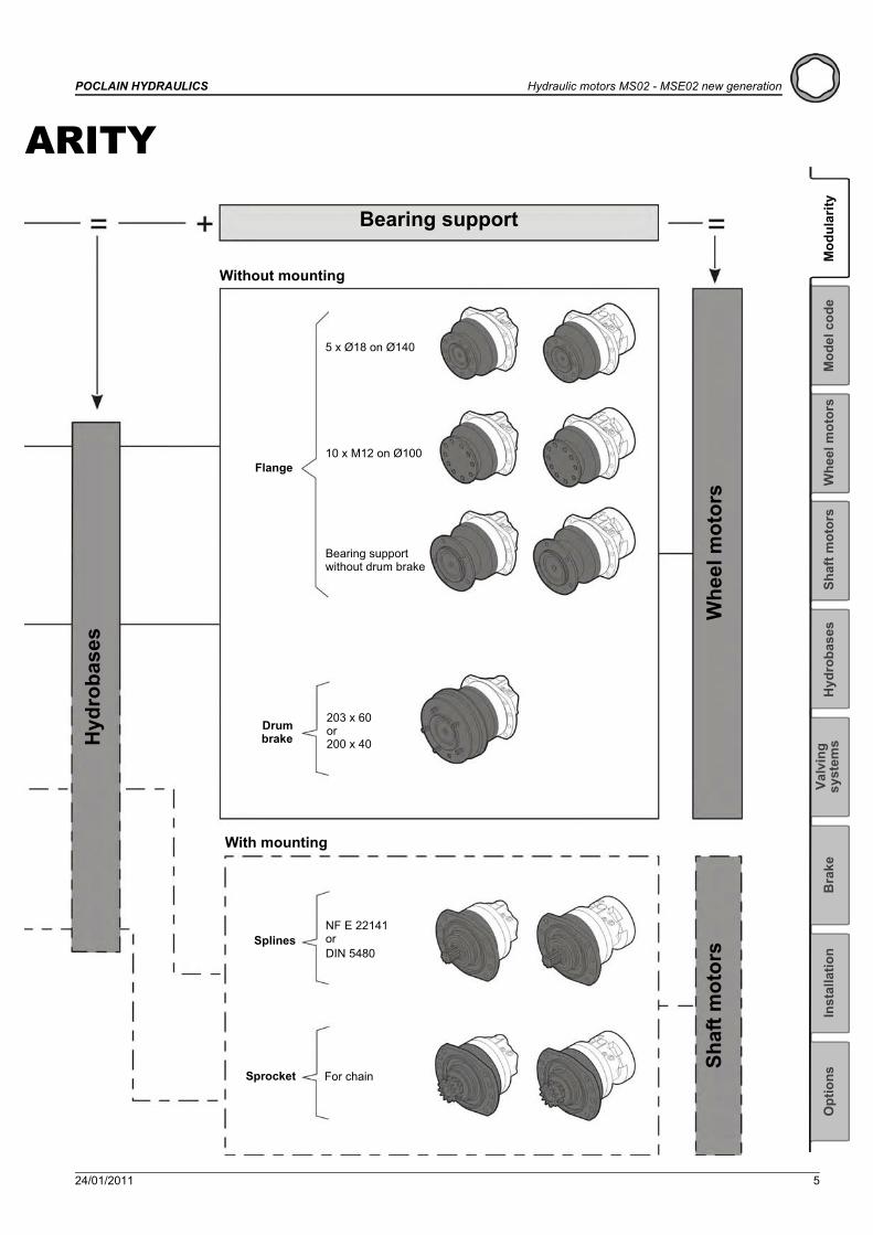
ARITY
Bearing support
Drumbrake
Shaf
t mot
ors
Whe
el m
otor
s
Flange
Splines
Sprocket
5 x Ø18 on Ø140
10 x M12 on Ø100
203 x 60or200 x 40
NF E 22141orDIN 5480
For chain
Bearing support without drum brake
Hyd
roba
ses
With mounting
Without mounting

6 24/01/2011
Hydraulic motors MS02 - MSE02 new generation POCLAIN HYDRAULICS
MODEL
D1Valving type1-displacement valving 1
2-displacement &Twin-Lock™ valving(Clockwise)
Ratio 2 DRatio <2 ERatio >2 F
2-displacement &Twin-Lock™ valving(Counterclockwise)
Ratio 2 GRatio <2 HRatio >2 J
D2Valving cover
Without mounting With mounting1 displacement / 2 displacements 1 2Exchange 4 5Twin-Lock™ D E
F123Rear brakeWith rear brake F 0 3Without rear brake (reinforced plate) R 0 2
S 0 2E
1
C
1 2
D
3 1 2
F
3M 0 2S
M
D3Connection type
Standard High FlowGAZ (BSPP) ISO 1179-1 3 GMetric ISO 9974-1 4 MUNF (SAE) ISO 11926-1 A U
C1Cam ring type
1 displacement 2 displacementscm3/tr [cu.in/rev.]
Cam
s w
ith
equa
l lob
es
MS02
172 [10.5] 86 [5.2] 8
213 [13.0] 107 [6.5] 0
235 [14.3] 118 [7.2] 1
255 [15.6] 128 [7.8] 2
MSE02
332 [20.2] 166 [10.1] 0
364 [22.2] 182 [11.1] 1
398 [24.3] 199 [12.1] 2
Cam
s w
ith
uneq
ual l
obes MS02
213 [13.0]86 [5.2]
A128 [7.8]
192 [11.7]86 [5.2]
N107 [6.5]
MSE02 332 [20.2]133 [8.1]
A199 [12.1]
Brake
Valving System
Torque Module
MODEL CODE

24/01/2011 7
POCLAIN HYDRAULICS Hydraulic motors MS02 - MSE02 new generation
Hyd
roba
ses
Bra
keSh
aft m
otor
sO
ptio
nsW
heel
mot
ors
Inst
alla
tion
Valv
ing
syst
ems
Mod
ular
ityM
odel
cod
e
CODE
Y1 2
P
3 4 1 2
S
3 4 5 6
P3Shaft typeFlangeWithout studs 1With studs + nuts 2With studs 3Threaded holes 4
Male shafts (if P2 = A)NF E 22141 splines 1DIN 5480 splines 5Dual sprocket for chain C
P4Drum brake
A Without cable 5 studsM16 x 1.5
on dia. 160200 x 40B M8
connectionRight-hand cable outlet
C Left-hand cable outlet7 Without cable 5 studs
M14 x 1.5 ondia. 140. Rim
centering:dia. 92.7
203 x 60
8 M8 connection
Right-hand cable outlet9 Left-hand cable outletH Hook
connectionRight-hand cable outlet
J Left-hand cable outlet4 Without cable
5 studsM14 x 1.5
on dia. 130
5 M8 connection
Right-hand cable outlet6 Left-hand cable outletE Hook
connectionRight-hand cable outlet
F Left-hand cable outletQ Without cable
5 studsM14 x 1.5
on dia. 140
R M8 connection
Right-hand cable outletS Left-hand cable outletT Hook
connectionRight-hand cable outlet
U Left-hand cable outlet
S2-6Options
1 Fluorinated elastomer seals2 T4 Speed sensor installed3 Brake environmental cover without plug6 Industrial bearing support7 Diamond™8 Predisposition for speed sensor9 Chassis mounting on cam ring sideA Hollow shaftB Drain on the bearing supportD Special paint or no paintG Special wheel rim mountingH High efficiencyJ Surface heat treatment of the shaftM High speed or reduced charge pressureP Customized identification plateS TR Speed sensor installed
S1Standard
YAdditional drain on valving systems (Steel plug)
Reinforced sealing
P2Bearing supportWithout shaft 05 x Ø18 on Ø140 110 x M12 on Ø100 25 x Ø18 on Ø130 7Support without drum brake G
Drum brake (200 x 40) Mineral HDOT 3&4 J
Drum brake (203 x 60) Mineral KDOT 3&4 L
For male shaft bearing support A
P1Front unitWithout bearing support 0Without mounting 1Lug mounting 2Shaft side mounting 3
Bearing support

8 24/01/2011
Hydraulic motors MS02 - MSE02 new generation POCLAIN HYDRAULICS
Methodology :This document is intended for manufacturers of machines that incorporate Poclain Hydraulics products. It describes the technical characteristics of Poclain Hydraulics products and specifies installation conditions that will ensure optimum operation. This document includes important comments concerning safety. They are indicated in the following way:
This document also includes essential operating instructions for the product and general information. These are indicated in the following way:
The views in this document are created using metric standards. The dimensional data is given in mm and in inches (inches are between brackets and italic)
Safety comment.
Essential instructions.
General information .
Information on the model number.Information on the model code.
Weight of component without oil.
Volume of oil.
Units.
Tightening torque.
Screws.
Information intended for Poclain-Hydraulics personnel.

24/01/2011 9
POCLAIN HYDRAULICS Hydraulic motors MS02 - MSE02 new generation
Hyd
roba
ses
Bra
keSh
aft m
otor
sO
ptio
nsIn
stal
latio
nVa
lvin
g sy
stem
sM
odel
cod
eM
odul
arity
Whe
el m
otor
s
WHEEL MOTORDimensions for standard 1-displacement motor
Dimensions for standard 2-displacements motor
26 kg [57 lb] 32 kg [70 lb]
0,80 L [48 cu.in] 0,70 L [42 cu.in]
1 1 1 01 2
P
3 4
Without brake With brake
28 kg [62 lb] 34 kg [75 lb]
1,00 L [60 cu.in] 1,00 L [60 cu.in]
143,5 ± 1,15 [5.65 ± 0.05]
Ø 1
55 [6
.1 d
ia.]
14 [0.55]
304,2 max. [11.98 max.]
255,7 max. [10.07 max.]
6,5 [0.26]10 [0.39]
X110,5 ± 0,6 [4.35 ± 0.0236]
Ø18
0
[7
.086
6 di
a.
]
67 [2.64]62 [2.44]
36 [1.42]32 [1.26]
67 [2
.64]
0 -0,1
50 -0
.006
Ø 1
69
[
6.65
dia
.
]
Ø 9
2,7
± 0,
1[3
.649
dia
. ± 0
.004
]
18
8 ±
4 [7
.4 d
ia. ±
0.1
6]
35 [1.38]
36 [1.42]
34,5 [1.36]
40 [1.57]
0 +5,4
0 +0.2
1
Ø 188[7.44 dia.]
Ø 210[8.27 dia.]
Ø 235[9.25 dia.]
R A 1
2
Y X
2x5 Ø14
[0.55 dia. ]
+0,25-0,10
+0.0098-0.0039
15°
15°
15°
15°
80 [
3.15
]
27° 30'
Y
A
R1
1 1 1 01 2
P
3 4Without brake With brake

10 24/01/2011
Hydraulic motors MS02 - MSE02 new generation POCLAIN HYDRAULICS
Dimensions for standard Twin-Lock™ motor
Dimensions for standard motor with exchange
28 kg [62 lb] 34 kg [75 lb]
1,00 L [60 cu.in] 1,00 L [60 cu.in]
Ø 1
55 [6
.1 d
ia.]
Ø 1
80
[7
.08
dia.
] 0 -0
,15
0 -0,0
06
143,5 ± 1,15 [5.65 ± 0.05]
14 [0.55]
304,2 max. [11.98 max.]257,2 max. [10.13 max.]
10 [0.39]6,5 [0.26]
Ø 1
69
[6,
65 d
ia.
]
Ø 9
2,7
± 0,
1[3
.65
dia.
± 0
.004
]
Ø 1
88 ±
4 [7
,4 d
ia. ±
0.1
6]
0 +0,2
1 0 +5
,4
X110,5 [4.35]
Ø 188[7.44 dia.]
Ø 210[8.27 dia.]
Ø 235[9.25 dia.]
A1
1
X
2x5 Ø14[2x5 0,55 dia.]
15°
15°
15°
15°
80[3
.15]
34 [1.34] 34 [1.34]
R A2
2
37°
65 [2
.56]
49,65 [1.95]30,35 [1.2]
3°
A1,R
A2
1 1 1 01 2
P
3 4
Without brake With brake
28 kg [62 lb] 34 kg [75 lb]
1,05 L [63 cu.in] 1,05 L [63 cu.in]
Ø 188[7.44 dia.]
Ø 210[8.27 dia.]
Ø 235[9.25 dia.]
LX
2x5 Ø14[2x5 0,55 dia.]
15°
15°
15°
15°
80[3
.15]
34 [1.34] 34 [1.34]
R 1
2
3°
54[2.13]
Ø 1
55 [6
.1 d
ia.]
Ø 1
80
[7
.08
dia.
] 0 -0
,15
0 -0,0
06
143,5 ± 1,15 [5.65 ± 0.05]
14 [0.55]
304,2 max. [11.98 max.]257,2 max. [10.13 max.]
10 [0.39]6,5 [0.26]
Ø 1
69
[6,
65 d
ia.
]
Ø 9
2,7
± 0,
1[3
.65
dia.
± 0
.004
]
Ø 1
88 ±
4 [7
,4 d
ia. ±
0.1
6]
0 +0,2
1 0 +5
,4
X110,5 [4.35]
65 [2
.56]
49 [1.93]
38 [1.50]
41 [1.61]
L
1
R
1 1 1 01 2
P
3 4
Exchange
Without brake With brake

24/01/2011 11
POCLAIN HYDRAULICS Hydraulic motors MS02 - MSE02 new generation
Hyd
roba
ses
Bra
keSh
aft m
otor
sO
ptio
nsIn
stal
latio
nVa
lvin
g sy
stem
sM
odel
cod
eM
odul
arity
Whe
el m
otor
s
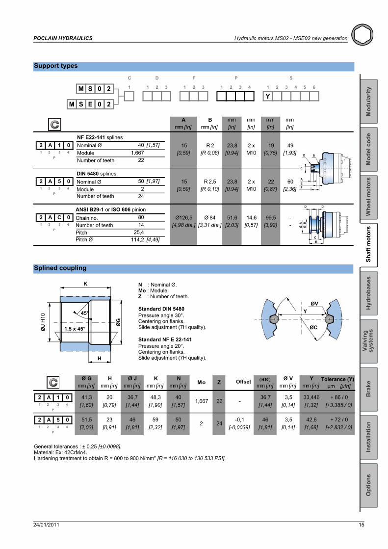
Support types
Studs
M 0 2Y
S 1
C
1 2
D
3 1 2
F
3 1 2
P
3 4 1 2
S
3 4 5 6
S 0 2EM
Amm [in]
Bmm [in]
Cmm [in]
Dmm [in]
Emm [in]
Nmm [in]
Lmm [in]
1 1 1 01 4
1 7 1 01 4
1 2 4 01 4
1 G 1 01 4
1 H 31 J 3 _ [6,30 dia.] [8,70 dia.]1 4
1 K 31 L 3 [3,65 dia.] [5,51 dia.] [8,70 dia.]1 4
[3,65 dia.]Ø 92,7
2 3 P
Ø 140 Ø 169 143,4 Ø 179,5 Ø 18 5 x M14x1.5
10[0,39][0,71 dia.][7,07 dia.][5,65][6,65 dia.][5,51 dia.]
Ø 77,6 Ø 130 Ø 169 140,6 Ø 179,5 Ø 18 5 x M14x1.5
102 3
P[3,06 dia.] [5,12 dia.] [6,65 dia.] [5,54] [7,07 dia.] [0,71 dia.] [0,39]
2 3 P
Ø 92,7 Ø 140 Ø 221 193[7,60]
25,5[1,00]
5 x M14x1.5
- Ø 100 Ø 120 142,9 Ø 179,5 10 x M12x1.75 -
11,252 3
P- [3,94 dia.] [4,72 dia.] [5,63] [7,07 dia.] [0,44]
Ø 92,7 Ø 140 Ø 168 185,5 Ø 179,5 Ø 18 5 x M14x1.52 3
P[3,65 dia.] [5,51 dia.] [6,61 dia.]
193
12[7,30] [7,07 dia.] [0,71 dia.] [0,47]
[7,60] [1,20]2 3
P
5 x M16x1.5
30,5_ Ø 160 Ø 221
Wheel rim mountings
Also see ’Brakes’ section (thumbnail opposite).
Pmm [in]
C min.mm [in]
C max.mm [in]
Dmm [in] Class
(1)*N.m [lb.ft]
(2)*N.m [lb.ft]
Standard studs M14x1.5 45 [1.77] 5 [0.20] 18 [0.71] 16,5 [0.65] 12,9 200 [147.5] 250 [184.4]
See generic installation motors N°801478197L.
See option G for non standard studs.
(*) The tightening torques are given for the indicated loads.(1) Wheel rim : Suggested tightening torque for wheel rim mountings (Re steel disc > 240 N/mm² [>34 800 PSI]).(2) Standard : Suggested tightening torque in other cases (Re steel flange 360 > N/mm² [>52 215 PSI])

12 24/01/2011
Hydraulic motors MS02 - MSE02 new generation POCLAIN HYDRAULICS
Radial load and service life of bearings curves
The service life of the components is influenced by the pressure.You must check that the combination of forces applied (Axial load / Radial load) is compatible with the permissible loads for the components, and that the resulting service lives of these components complies with the application's specifications. For an accurate calculation, consult your Poclain Hydraulics application engineer.
Permissible radial loads Service life of bearingsMax. permissible loads: 0 tr/min [0 RPM]; 0 bar [0 PSI]. L : Millions B10 revolutions at 150 bars (average
pressure), with 25 cSt fluid.Continuous permissible loads: > 0 tr/min [> 0 RPM]; 275 bar [3 988 PSI].
Test conditions: code 0 displacement, without axial load, shaft treated, class 10.9 and 12.9 chassis mountings class 12.9 wheel rim mountings.
P1 2 3 4
1 1 1 01 7 1 0
P1 2 3 4
1 2 4 0
P1 2 3 4
1 G 11 H 31 J 31 K 31 L 3

24/01/2011 13
POCLAIN HYDRAULICS Hydraulic motors MS02 - MSE02 new generation
Hyd
roba
ses
Bra
keO
ptio
nsW
heel
mot
ors
Inst
alla
tion
Valv
ing
syst
ems
Mod
el c
ode
Mod
ular
itySh
aft m
otor
s
SHAFT MOTORDimensions for standard 1-displacement motor
Dimensions for standard 2-displacements motor
26 kg [57 lb] 32 kg [70 lb]
0,80 L [48 cu.in] 0,70 L [42 cu.in]
2 A 5 01 2
P
3 4Without brake With brake
2 A 5 01 2
P
3 4
30 kg [66 lb] 36 kg [79 lb]
1,00 L [60 cu.in] 1,00 L [60 cu.in]
Without brake With brake
36 [1.42] 40 [1.57]X
214,2 ± 0,85 [8.43 ± 0.0335]
R
139,7 ± 0,7 [5.5 ± 0.0276]A
165,7 ± 0,7 [6.52 ± 0.0276]
1
135,7 ± 0,7 [5.34 ± 0.0276] Y
170,7 ± 0,7 [6.72 ± 0.0276]
251,4 ± 0,9 [9.9 ± 0.035]
15°
15°
15°
15°
Ø188 [7.44 dia.]
Ø 210 [8.27 dia.]
+0,25-0,102x5 Ø 14
[2x5 0.55 dia. ]
Ø 235 [9.25 dia.]
R A 1
2+0,0098-0,0039
80 [
3.15
]
Y
Ø 198 [7.8 dia.]
12 [0.47]
179,
97 ±
0,0
3 [7
.09
dia.
± 0
.001
2]
Ø 1
01 [3
.976
dia
.]
X
27°30'
10 [0.39]
Ø 1
55 [6
.1 d
ia.]
289,5 max. [11.4 max.]
338 max. [13.3 max.]
67 [2
,64]
202,7 ± 1,1 [7.98 ± 0.043] 24,5 ± 1 [0.965 ± 0.039]
24,4 max. [0.96 max.]
35 [1.38] 34,5 [1.36]
2 A 5 01 2
P
3 4

14 24/01/2011
Hydraulic motors MS02 - MSE02 new generation POCLAIN HYDRAULICS
Dimensions for standard Twin-Lock™ motor
Dimensions for standard motor with exchange
2 A 5 01 2
P
3 4
12 [0.47]10 [0.39]
Ø 188[7.44 dia.]
Ø 210[8.27 dia.]
Ø 235[9.25 dia.]
A1
1
X
2x5 Ø14[2x5 0,55 dia.]
15°
15°
15°
15°
80[3
.15]
34 [1.34] 34 [1.34]
R A2
2
37°
3°
Ø 1
79,9
7 ±
0,03
[7.0
9 di
a. ±
0.0
01]
Ø 1
01[3
.98
dia.
]
Ø 1
55 [6
.1 d
ia.]
65 [2
.56]
251,2 ± 0,9 [9.9 ± 0.035]
153,35 ± 0,7 [6.04 ± 0.027]
134,05 ± 0,7 [5.28 ± 0.027] X
A1,R
A2
24,5 ± 1 [0.96 ± 0.039]
338 max. [13.3 max.]
289,5 max. [11.4 max.]
202,7 ± 1,1 [7.98 ± 0.043]
30 kg [66 lb] 36 kg [79 lb]
1,05 L [63 cu.in] 1,05 L [63 cu.in]
Without brake With brake2 A 5 01 2
P
3 4
Ø 198[7.8 dia.]
Ø 210[8.27 dia.]
Ø 235[9.25 dia.]
L1 X
2x5 Ø14[2x5 0,55 dia.]
15°
15°
15°
15°
80[3
.15]
34 [1.34] 34 [1.34]
R
2
3°
54[2.13]
12 [0.47]10 [0.39]
Ø 1
79,9
7 ±
0,03
[7.0
9 di
a. ±
0.0
01]
Ø 1
01[3
.98
dia.
]
Ø 1
55 [6
.1 d
ia.]
65 [2
.56]
251,4 [9.9]214,2 [8.43]
152,7 [6.01]
144,7 [5.7]
141,7 [5.58] XL R
24,4 [0.96]
338 max. [13.3 max.]
291,1 max. [11.46 max.]
204,2 [8,04]
1
Exchange valve
24/01/2011 15
POCLAIN HYDRAULICS Hydraulic motors MS02 - MSE02 new generation
Hyd
roba
ses
Bra
keO
ptio
nsW
heel
mot
ors
Inst
alla
tion
Valv
ing
syst
ems
Mod
el c
ode
Mod
ular
itySh
aft m
otor
s
Support types
Splined coupling
General tolerances : ± 0.25 [±0.0098].Material: Ex: 42CrMo4.Hardening treatment to obtain R = 800 to 900 N/mm² [R = 116 030 to 130 533 PSI].
M 0 2Y
S 1
C
1 2
D
3 1 2
F
3 1 2
P
3 4 1 2
S
3 4 5 6
S 0 2EM
Amm [in]
Bmm [in]
mm [in]
mm [in]
mm [in]
mm [in]
2 A 1 0 40 [1,57]1 4 1.667
22
2 A 5 0 50 [1,97]1 4 2
24
2 A C 0 801 4 14
25,4114,2 [4,49]
[1,93]23,8 19 49
[0,75][0,94]2 x M10[0,59]
152 3
P
R 2[R 0,08]
602 3
P[0,59] [R 0,10] [0,94] [0,87] [2,36]
15 R 2,5 23,8
Ø 84 51,6
222 x M10
99,5 -2 3
P[4,98 dia.] [3,31 dia.] [2,03] [3,92] -
14,6[0,57]
Ø126,5
Number of teeth
Number of teeth
Number of teeth
ANSI B29-1 or ISO 606 pinion
NF E22-141 splinesNominal ØModule
DIN 5480 splinesNominal ØModule
Chain no.
Pitch ØPitch
N : Nominal Ø.Mo : Module.Z : Number of teeth.
Standard DIN 5480Pressure angle 30°.Centering on flanks.Slide adjustment (7H quality).
Standard NF E 22-141Pressure angle 20°.Centering on flanks.Slide adjustment (7H quality).
ØVY
ØC
K
H
1.5 x 45°
45°
ØG
ØJ
H10
Ø Gmm [in]
Hmm [in]
Ø Jmm [in]
Kmm [in]
Nmm [in] Mo Z ( H10 )
mm [in]Ø V
mm [in]Y
mm [in] μm [μin]
2 A 1 01 4
2 A 5 01 4
51,5 23 462 3
P[2,03] [0,91] [1,81]
[1,62]41,3
2 3 P
20[0,79]
36,7 40[1,57][1,44]
48,3[1,90]
[-0,0039]59
[2,32]50 -0,1
[1,97]2 24
42,6
+ 86 / 0[+3.385 / 0]
+ 72 / 0
[1,32]33,446
[1,81] [1,68][0,14] [+2.832 / 0]3,546
[1,44]36,7
221,6673,5
[0,14]-
Tolerance (Y)Offset

16 24/01/2011
Hydraulic motors MS02 - MSE02 new generation POCLAIN HYDRAULICS
Radial load and service life of bearings curves
The service life of the components is influenced by the pressure.You must check that the combination of forces applied (Axial load / Radial load) is compatible with the permissible loads for the components, and that the resulting service lives of these components complies with the application's specifications. For an accurate calculation, consult your Poclain Hydraulics application engineer.
Permissible radial loads Service life of bearingsMax. permissible loads: 0 tr/min [0 RPM]; 0 bar [0 PSI]. L : Millions B10 revolutions at 150 bars (average
pressure), with 25 cSt fluid.Continuous permissible loads: > 0 tr/min [> 0 RPM]; 275 bar [3 988 PSI].
Test conditions: code 0 displacement, without axial load, shaft treated, class 10.9 and 12.9 chassis mountings.
2 A 1 01 2 3 4
P
2 A 5 01 2 3 4
P

24/01/2011 17
POCLAIN HYDRAULICS Hydraulic motors MS02 - MSE02 new generation
Hyd
roba
ses
Bra
keO
ptio
nsW
heel
mot
ors
Inst
alla
tion
Valv
ing
syst
ems
Mod
el c
ode
Mod
ular
itySh
aft m
otor
s
Radial load and service life of bearings curves
The service life of the components is influenced by the pressure.You must check that the combination of forces applied (Axial load / Radial load) is compatible with the permissible loads for the components, and that the resulting service lives of these components complies with the application's specifications. For an accurate calculation, consult your Poclain Hydraulics application engineer.
Permissible radial loads Service life of bearingsMax. permissible loads: 0 tr/min [0 RPM]; 0 bar [0 PSI]. L : Millions B10 revolutions at 150 bars (average
pressure), with 25 cSt fluid.Continuous permissible loads: > 0 tr/min [> 0 RPM]; 275 bar [3 988 PSI].
Test conditions: code 0 displacement, without axial load, shaft treated, class 10.9 and 12.9 chassis mountings.
2 A C 01 2 3 4
P

18 24/01/2011
Hydraulic motors MS02 - MSE02 new generation POCLAIN HYDRAULICS

24/01/2011 19
POCLAIN HYDRAULICS Hydraulic motors MS02 - MSE02 new generation
Bra
keSh
aft m
otor
sO
ptio
nsW
heel
mot
ors
Inst
alla
tion
Valv
ing
syst
ems
Mod
el c
ode
Mod
ular
ityH
ydro
base
s
HYDROBASESDimensions for 1-displacement hydrobase
Dimensions for 2-displacements hydrobase
13,8 kg [30 lb] 19,9 kg [44 lb]
0,35 L [21 cu.in] 0,45 L [27 cu.in]
1 2
D
3
1 21 2
D
3
1 1Without brake With brake
18,8 kg [41 lb] 24,9 kg [55 lb]
0,35 L [21 cu.in] 0,45 L [27 cu.in]
28,7 [1.16]
Ø 1
55 [6
.1 d
ia.]
14 [0.55]
191,2 ± 0,85 [7.53 ± 0.03]
141,7 ± 0,9 [5.58 ± 0.03]
5,05 [0.20]
7,95 [0.31]X110,5 ± 0,6 [4.35 ± 0.0236]
67 [2.64]62 [2.44]
36 [1.42]32 [1.26]
67 [2
.64]
Ø 1
32,2
[5.2
0 di
a.]
Ø A
184,
5
[7
.26
dia.
]
35 [1.38]
36 [1.42]
34,5 [1.36]
40 [1.57]
Ø 188[7.44 dia.]
Ø 210[8.27 dia.]
Ø 235[9.25 dia.] R A 1
2
Y X
2x5 Ø14
[0.55 dia. ]
+0,25-0,10
+0.0098-0.0039
15°
15°
15°
80 [
3.15
]
27° 30'
Y
A
R1
MSE
MS
+1 0+0
.04
0
1 2
D
3
21 2
D
3
1
Without brake With brake
20 24/01/2011
Hydraulic motors MS02 - MSE02 new generation POCLAIN HYDRAULICS
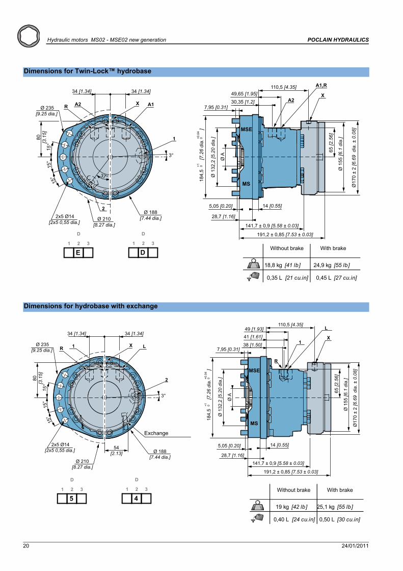
Dimensions for Twin-Lock™ hydrobase
Dimensions for hydrobase with exchange
18,8 kg [41 lb] 24,9 kg [55 lb]
0,35 L [21 cu.in] 0,45 L [27 cu.in]
Ø17
0 ±
2 [6
.69
dia
. ± 0
.08]
Ø 1
55 [6
.1 d
ia.]
5,05 [0.20] 14 [0.55]
MSE
MS
7,95 [0.31]
28,7 [1.16]
X110,5 [4.35]
Ø 188[7.44 dia.]Ø 210
[8.27 dia.]
Ø 235[9.25 dia.]
A1
1
X
2x5 Ø14[2x5 0,55 dia.]
15°
15°
15°
80[3
.15]
34 [1.34] 34 [1.34]
R A2
2
37°
65 [2
.56]
49,65 [1.95]30,35 [1.2]
3°
A1,R
A2
Ø 1
32,2
[5.2
0 di
a.]
Ø A
184,
5
[7
.26
dia.
]+1 0
+0.0
40
191,2 ± 0,85 [7.53 ± 0.03]
141,7 ± 0,9 [5.58 ± 0.03]
1 2
D
3
E1 2
D
3
DWithout brake With brake
19 kg [42 lb] 25,1 kg [55 lb]
0,40 L [24 cu.in] 0,50 L [30 cu.in]
Ø 188[7.44 dia.]
Ø 210[8.27 dia.]
Ø 235[9.25 dia.]
LX
2x5 Ø14[2x5 0,55 dia.]
15°
15°
15°
80[3
.15]
34 [1.34] 34 [1.34]
R 1
2
3°
54[2.13]
Ø 1
55 [6
.1 d
ia.]
28,7 [1.16]
14 [0.55]
7,95 [0.31]
5,05 [0.20]
X
110,5 [4.35]
65 [2
.56]
49 [1.93]
38 [1.50]
41 [1.61]
L
1
R
MSE
MS
Ø 1
32,2
[5.2
0 di
a.]
Ø A
184,
5
[7
.26
dia.
]+1 0
+0.0
40
191,2 ± 0,85 [7.53 ± 0.03]
141,7 ± 0,9 [5.58 ± 0.03]
Ø17
0 ±
2 [6
.69
dia
. ± 0
.08]
1 2
D
3
51 2
D
3
4Without brake With brake
Exchange

24/01/2011 21
POCLAIN HYDRAULICS Hydraulic motors MS02 - MSE02 new generation
Bra
keSh
aft m
otor
sO
ptio
nsW
heel
mot
ors
Inst
alla
tion
Valv
ing
syst
ems
Mod
el c
ode
Mod
ular
ityH
ydro
base
s
Cylinder block splines(as per standard NF E22-141)
1,667 2240
Y ØVØA
33,446 [1,317]
Z
3,33 [0,131][1,575]
ØC
36,72 [1,446]
Dimension on 2 pinsModule
ØC
YØV
You are advised to have the installation validated by your Poclain Hydraulics application engineer before using the hydraulic unit in an application.
We must provide you with a detailed plan of the interface for any hydraulic unit use, consult your Poclain Hydraulics sales engineer.

22 24/01/2011
Hydraulic motors MS02 - MSE02 new generation POCLAIN HYDRAULICS
Efficiency and output torque
Overall efficiency Actual output torqueAverage values given for guidance for code 0 displacement after 100 hours of operation with HV46 hydraulic fluid at 50°C [122°F].
MS02
MSE02
The starting torque is taken to be approximately 85% of the first value for available pressure. For a precise calculation, consult your Poclain Hydraulics application engineer.

24/01/2011 23
POCLAIN HYDRAULICS Hydraulic motors MS02 - MSE02 new generation
Hyd
roba
ses
Bra
keSh
aft m
otor
sO
ptio
nsW
heel
mot
ors
Inst
alla
tion
Mod
el c
ode
Mod
ular
ityVa
lvin
g sy
stem
s
VALVING SYSTEMSHydraulic connections
A UNF (SAE)3 Gaz (BSPP)4
A UNF (SAE)3 Gaz (BSPP)4
1 2A UNF (SAE) 3/4" 9/16"3 Gaz (BSPP) M18 M144 G3/4 G1/4
MS 450 [6 527]MSE 400 [5 802]
ISO 1 179-1
ISO 11 926-1
ISO 9 974-1
ISO 11 926-1
9/16"-18 UNFX
7/8"-14 UNF
ISO 9 974-1
7/8"-14 UNF
ISO 9 974-1
120 [1 740]
ISO 9 974-1 M10x1.0
bar [PSI] 2,5 [36] 30 [435] 30 [435]
M14x1.5
R-A1-A2
G1/2M22x1.5
G1/4ISO 1 179-1
G1/2M22x1.5 M14x1.5
7/8"-14 UNFG1/2
3/4"-16 UNF 9/16"-18 UNFR-L 1 - 2 XTX
G1/49/16''-18 UNF
M14x1.5G1/4
M22x1.5G1/4ISO 1 179-1
G1/4
M14x1.5G3/8
Y X1 - 2R-AISO 11 926-1
M18x1.5
9/16''-18 UNF 9/16"-18 UNF
M14x1.5
bar [PSI] 15 [218]
0 2S 1 1 2
M 0 2S E
MY1 2 3 4 5 6
S1 2 3 4
PDC F1 2 33
Standards Power supply Case drain Control of parking brake
2nd displacement
control
Control of drum brake
Max.pressures
Metric
Metric
Metric
Instantaneous pressurepeaks resistance
You are strongly advised to use the fluids specified in brochure “Installation guide” N° 801478197L.
To find the connections’ tightening torques, see the brochure “Installation guide” N° 801478197L.

24 24/01/2011
Hydraulic motors MS02 - MSE02 new generation POCLAIN HYDRAULICS
Exchange
- Fitted valve
When a codification is requested, you must specify needed characteristics.
bar [PSI] bar [PSI] L/min [GPM] bar [PSI]
13,0±1,0
P1 P2Q2
[2,51±0.66] [363]259,5±2,5[218]
24 [348]
[450]
18 [261] 3,7±0,5 [0,98±0.13]
[3,43±0.26] 31[290]
8,5±1,5 [123±21.75]
20
10,0±1,0 [145±14.5]
8,5±1,5 [123±21.75]
15
Opening pressure of selector
Q L/min [GPM]
�Pbar [PSI]
P1
P2
Q2

24/01/2011 25
POCLAIN HYDRAULICS Hydraulic motors MS02 - MSE02 new generation
Hyd
roba
ses
Shaf
t mot
ors
Opt
ions
Whe
el m
otor
sIn
stal
latio
nVa
lvin
g sy
stem
sM
odel
cod
eM
odul
arity
Bra
ke
BRAKES
Rear brake
M 0 2Y
S 1
C
1 2
D
3 1 2
F
3 1 2
P
3 4 1 2
S
3 4 5 6
S 0 2EMF 0 3
Brake principleThis is a multidisc brake which is activated by a lack of pressure. The spring exerts a force on the piston, which resses on the fixed and mobile discs, and immobilizes the shaft. The braking torque decreases in linear proportion to the brake release pressure.
Emergency brake release
M12
42 N.m [30.9 lb.ft]
2 500 Nm [1 840 lb.ft]
1 625 Nm [1 200 lb.ft]
1 875 Nm [1 380 lb.ft]12 bar [174 PSI]30 bar [435 PSI]
100 cm³ [6,1 cu.in]16 cm³ [1,0 cu.in]
38 179 J
F 0 3Parking brake torque at 0 bars on housing (new brake)Dynamic emergency braking torque at 0 bars on housing (max. 10 uses of emergency brakes)Residual parking braking at 0 bars on housing *Min. brake release pressureMax. brake release pressureOil capacityVolume for brake releaseMax. energy dissipation
* After emergency brake has been used
Do not run-in the multidisc brakes.
A functional check of the parking brake must be carried out each time it is used as an auxiliary brake (or emergency brake). For all vehicles capable of speeds over 25 km/hour, please contact your Poclain Hydraulics application engineer.

26 24/01/2011
Hydraulic motors MS02 - MSE02 new generation POCLAIN HYDRAULICS
Drum brake(200 x 40 or 203 x 60)Diameter of brake pads : Ø 200 [7.87 dia.] or Ø 203 [7.99 dia.] Width of friction surface : 40 [1.57] or 60 [2.36]
M 0 21 3 Y
S 1
C
1 2
D
3 1 2
F
3 1 2
P
3 4 1 2
S
3 4 5 6
S 0 2EM
780 N.m [575 lb .ft] 1 650 N.m [1 217 lb .ft]73 bar [1 059 PSI] 73 bar [1 059 PSI]
1 300 N.m [959 lb .ft] 2 750 N.m [2 028 lb .ft]120 bar [1 740 PSI] 120 bar [1 740 PSI]
1,2 cm³ [0,07 cu.in] 2,3 cm³ [0,14 cu.in]
1 300 N.m [959 lb .ft] 2 750 N.m [2 028 lb .ft]780 N [175 lb f] 1 650 N [371 lb f]
20 N [4 lb f] 37 N [8 lb f]A 7,4 mm [0,29 ''] 7,0 mm [0,28 '']B 8,5 mm [0,33 ''] 8,5 mm [0,33 '']A 11,1 mm [0,44 ''] 9,5 mm [0,37 '']B 12,8 mm [0,50 ''] 10,5 mm [0,41 '']
200 x 40 203 x 60BERAL 1106Automatic
YesYes
Stroke required to bring pads into contact
Max. stroke before automatic brake adjustment
BERAL 1117 or JURID 421Automatic
YesYes
Brake padsAsbestos free materialCompensation for wearHydraulically controlled dynamic brakingMax. permissible continuous brake torquePressure to obtain max. permissible continuous brake torqueMax. permissible brake torquePressure to obtain max. permissible brake torqueFluidMineralDOT 3/DOT4/SAE J1703Max. volume required to bring pads into contactMechanically controlled parking brakeMax. braking torqueMax permissible force on the cableForce required to bring pads into contact
HJ
KL
End viewof shaft
Cable
ControlThe drum brakes can be controlled hydraulically (service brake) and by a cable (mechanical control for parking brake).
The max. braking torque can only be obtained when the brake has been run in. Consult your Poclain Hydraulics application engineer.
Do not use hydraulic and mechanical brake controls simultaneously.
See also 'Wheel motor' section (thumbnail opposite)
When making a codification request, you must indicate the following information:- The material of the brake linings,- Fill out the technical questionnaire for validation of the brake.
Without cable
M8 connection Hook connection
200 x 40 � �
203 x 60 � � �
20 min.[0.79 min.]
M8
50[1.97]
30°

24/01/2011 27
POCLAIN HYDRAULICS Hydraulic motorsMS02 - MSE02 new generation
Hyd
roba
ses
Bra
keSh
aft m
otor
sO
ptio
nsW
heel
mot
ors
Valv
ing
syst
ems
Mod
el c
ode
Mod
ular
ityIn
stal
latio
n
INSTALLATIONCustomer’s chassis and wheel rim mountings
12,5
μm
[0.4
9 μi
n]
0,2
[0.0
08]
Take care over the immediate environment of the connections.
ØUmm [in] *240,00 120 N.m[9,45] [89 lb.ft]
(1) +0,3 [+0,012] 145 N.m-0,2 [ -0,008] [107 lb.ft]
10.9
12.9
10 M12 x 1,75
ØM (1)
mm [in]180,25[7,10]
Class
* : Min. values for torque and load to be transmitted
You don’t need to chamfer your chassis and wheel rim.
For more information see technical catalogue ’’ Installation guide N° 801478197L.
You are strongly advised to use the fluids specified in brochure “Installation guide” N° 801478197L.
To find the connections’ tightening torques, see the brochure “Installation guide” N° 801478197L.

28 24/01/2011
Hydraulic motors MS02 - MSE02 new generation POCLAIN HYDRAULICS
24/01/2011 29
POCLAIN HYDRAULICS Hydraulic motors MS02 - MSE02 new generation
Hyd
roba
ses
Bra
keSh
aft m
otor
sW
heel
mot
ors
Inst
alla
tion
Valv
ing
syst
ems
Mod
el c
ode
Mod
ular
ityO
ptio
ns
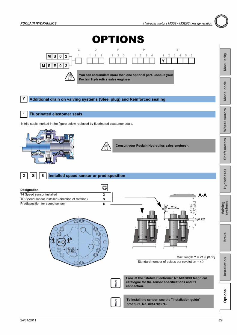
OPTIONS
You can accumulate more than one optional part. Consult your Poclain Hydraulics sales engineer.
Y Additional drain on valving systems (Steel plug) and Reinforced sealing
1 Fluorinated elastomer seals
Nitrile seals marked in the figure below replaced by fluorinated elastomer seals.
Consult your Poclain Hydraulics sales engineer.
2 S 8 Installed speed sensor or predisposition
M 0 2Y
S 1
C
1 2
D
3 1 2
F
3 1 2
P
3 4 1 2
S
3 4 5 6
S 0 2EM
DesignationT4 Speed sensor installed 2TR Speed sensor installed (direction of rotation) SPredisposition for speed sensor 8
A-A
Max. length Y =Standard number of pulses per revolution =
21,5 [0.85]40
Look at the "Mobile Electronic" N° A01889D technical catalogue for the sensor specifications and its connection.
To install the sensor, see the ''Installation guide'' brochure No. 801478197L.
30 24/01/2011
Hydraulic motors MS02 - MSE02 new generation POCLAIN HYDRAULICS
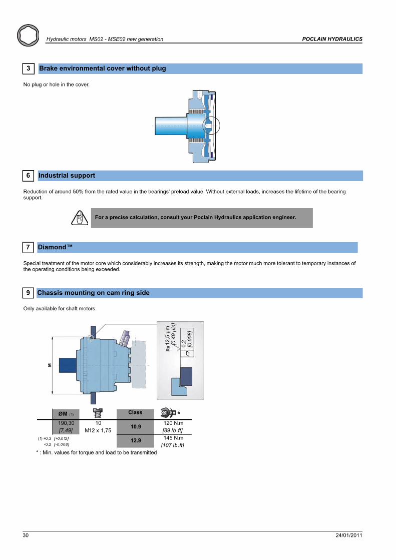
3 Brake environmental cover without plug
No plug or hole in the cover.
6 Industrial support
Reduction of around 50% from the rated value in the bearings' preload value. Without external loads, increases the lifetime of the bearing support.
7 Diamond™
Special treatment of the motor core which considerably increases its strength, making the motor much more tolerant to temporary instances of the operating conditions being exceeded.
9 Chassis mounting on cam ring side
Only available for shaft motors.
For a precise calculation, consult your Poclain Hydraulics application engineer.
ØM (1) *190,30 120 N.m[7,49] [89 lb.ft]
(1) +0,3 [+0,012] 145 N.m-0,2 [ -0,008] [107 lb.ft]
10 M12 x 1,75
10.9
12.9
* : Min. values for torque and load to be transmitted
12,5
μm
[0.4
9 μi
n]
0,2
[0.0
08]
Class

24/01/2011 31
POCLAIN HYDRAULICS Hydraulic motors MS02 - MSE02 new generation
Hyd
roba
ses
Bra
keSh
aft m
otor
sW
heel
mot
ors
Inst
alla
tion
Valv
ing
syst
ems
Mod
el c
ode
Mod
ular
ityO
ptio
ns
A Hollow shaft
B Drain on the bearing support
D Special paint or no paint
The motors are delivered with Poclain Hydraulics yellow ochre primer as standard.
Amm [in]
± [0,59 dia.] [6,90] ± [0,05]
mm [in]B
Ø 15 175,2 1,25
Radial load x 0.75No torque transmittable to the rear
GAZ (BSPP) E GISO 1179-1
G1/4 73,1±0.5 [2,88±0.019] 25° 76,1±0.9 [3,00±0.035] -G3/8 33±0.5 [1,3±0.019] 90±0.5 [3,54±0.019] - 60°
mm [in]mm [in]mm [in]mm [in]FB C D
�� �
�Wheel motorShaft motor
Consult your Poclain Hydraulics application engineer for other colors of primer or topcoat.

32 24/01/2011
Hydraulic motors MS02 - MSE02 new generation POCLAIN HYDRAULICS
G Special wheel rim mounting
H High efficiency
Reinforced piston sealing to improve volumetric efficiency.
J Treated shaft
Heat treatment on the indicated bearing radius and splines.
M High speed or reduced charge pressure
Option M leads to:
• In the case of MS02: Reduction in charge pressure.• In the case of MSE02: An increase in speed and a reduction in charge pressure.
(1) * (2) *mm [in] mm [in] mm [in] mm [in] N.m [lb.ft] N.m [lb.ft]
M14x1.5 50 [1,97] 23 [0,91]M14x1.5 62 [2,44] 33 [1,30]M16x1.5 50 [1,97] 23 [0,91] 21,0 [0,83] 300 [221,3] 380 [280,3]M10x1.25 10.9 [53,8]M12x1.75 10.9 [88,5]
P C min. C max. D
250 [184,4][0,65]12.9
200 [147,5]
73120
16,55 [0,20]
Consult your Poclain Hydraulics sales engineer.
Various studs
Screws
Class
For a precise calculation, consult your Poclain Hydraulics application engineer.
Treated areas
For a precise calculation, consult your Poclain Hydraulics application engineer.
24/01/2011 33
POCLAIN HYDRAULICS Hydraulic motors MS02 - MSE02 new generation
Hyd
roba
ses
Bra
keSh
aft m
otor
sW
heel
mot
ors
Inst
alla
tion
Valv
ing
syst
ems
Mod
el c
ode
Mod
ular
ityO
ptio
ns
P Customized identification plate
Your part number can be engraved on the plate.
Consult your Poclain Hydraulics application engineer for other possibilities.

34 24/01/2011
Hydraulic motors MS02 - MSE02 new generation POCLAIN HYDRAULICS


24/01/2011
More information on
Poclain Hydraulics reserves the right to make any modifications it deems necessary to the products described in this document without prior notification.The information contained in this document must be confirmed by Poclain Hydraulics before any order is submitted.Illustrations are not binding.The Poclain Hydraulics brand is the property of Poclain Hydraulics S.A.
Thirteen subsidiaries and a worldwide network of more than 150 distributors and partners …
A36313V
A36314W
A36315X
A36316Z
A36317A
A36319C
Not available
A36318B


![Catalogue Technique MS02-MSE02 en français. · 6 20/03/2009 Modular hydraulic motors MSE03 POCLAIN HYDRAULICS MODEL S E 03 1 C 12 D 312 F 3 M 1 450 [27,4] 225 [13,7] 2 500 [30,5]](https://static.documents.pub/doc/80x56/5f761173b68d9a37d97f725f/catalogue-technique-ms02-mse02-en-franfais-6-20032009-modular-hydraulic-motors.jpg)
