55
HSMFG1206 Rev. 1 5HPOMSP7 MANURE SPREADER OPERATOR’S MANUAL MS1337 MS1354 MS1368
| Date post: | 26-Jul-2018 |
| Category: |
Documents |
| Upload: | duongthuan |
| View: | 239 times |
| Download: | 0 times |

HSMFG1206 Rev. 1 5HPOMSP7
MANURE SPREADERO P E R A T O R ’ S M A N U A L
MS1337MS1354MS1368
TABLE OF CONTENTS
TABLE OF CONTENTS. . . . . . . . . . . . . . . . . . . . . . . . . . . . . . . . . . . . . . . . . . . . . . INSIDE COVER
WARRANTY & NOTES. . . . . . . . . . . . . . . . . . . . . . . . . . . . . . . . . . . . . . . . . . . . . . . . . . . . . . . . . . . . . . .1
DEALER PRE-DELIVERY & DELIVERY CHECKLIST. . . . . . . . . . . . . . . . . . . . . . . . . . . . . . . . . . . . 3
SPECIFICATIONS. . . . . . . . . . . . . . . . . . . . . . . . . . . . . . . . . . . . . . . . . . . . . . . . . . . . . . . . . . . . . . . . . . .5
BOLT TORQUE CHART. . . . . . . . . . . . . . . . . . . . . . . . . . . . . . . . . . . . . . . . . . . . . . . . . . . . . . . . . . . . . . 6
BE ALERT SYMBOL. . . . . . . . . . . . . . . . . . . . . . . . . . . . . . . . . . . . . . . . . . . . . . . . . . . . . . . . . . . . . . . . .7
SAFETY RULES. . . . . . . . . . . . . . . . . . . . . . . . . . . . . . . . . . . . . . . . . . . . . . . . . . . . . . . . . . . . . . . . . . 8-9
DANGER - WARNING DECALS. . . . . . . . . . . . . . . . . . . . . . . . . . . . . . . . . . . . . . . . . . . . . . . . . . . 10-11
OPERATION MS1337, MS1354 & MS1368. . . . . . . . . . . . . . . . . . . . . . . . . . . . . . . . . . . . . . . . . 12-14
ADJUSTMENTS. . . . . . . . . . . . . . . . . . . . . . . . . . . . . . . . . . . . . . . . . . . . . . . . . . . . . . . . . . . . . . . . 15-18
LUBRICATION GUIDE MS1337, MS1354 & MS1368. . . . . . . . . . . . . . . . . . . . . . . . . . . . . . . . . 19-21
DECAL LOCATION. . . . . . . . . . . . . . . . . . . . . . . . . . . . . . . . . . . . . . . . . . . . . . . . . . . . . . . . . . . . . .22-23
TROUBLE SHOOTING. . . . . . . . . . . . . . . . . . . . . . . . . . . . . . . . . . . . . . . . . . . . . . . . . . . . . . . . . . . . . . 24
OPTIONAL EQUIPMENT. . . . . . . . . . . . . . . . . . . . . . . . . . . . . . . . . . . . . . . . . . . . . . . . . . . . . . . . . . . . 24
ORDERING PARTS - ABOUT IMPROVEMENTS. . . . . . . . . . . . . . . . . . . . . . . . . . . . . . . . . . . . . . . .25
PARTS LISTS & DIAGRAMS MS1442H & MS1455H. . . . . . . . . . . . . . . . . . . . . . . . . . . . . . . . . 26-50
SERVICE RECORDS. . . . . . . . . . . . . . . . . . . . . . . . . . . . . . . . . . . . . . . . . . . . . . . . . . . . . . . . . . . . . . .51

-1-
NOTES
WARRANTY:Warranty coverage is provided by John Deere according to the terms of theAgricultural/Commercial & Consumer Equipment Warranty Statement. Carefully read thewarranty statement on the back of your original purchase order for details on coverageand limitations of this warranty.

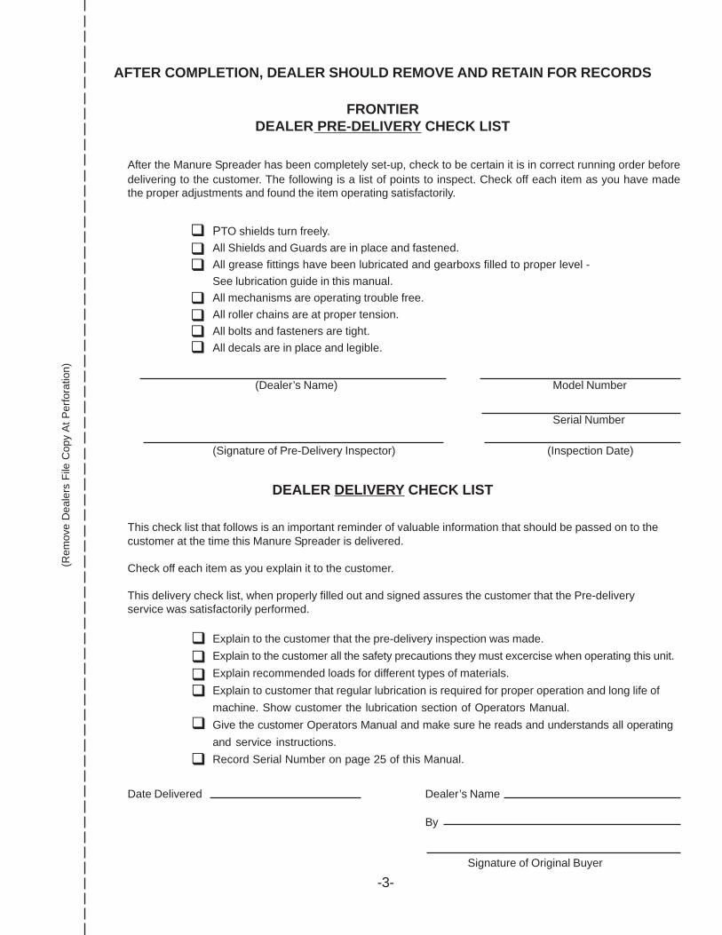
AFTER COMPLETION, DEALER SHOULD REMOVE AND RETAIN FOR RECORDS
FRONTIERDEALER PRE-DELIVERY CHECK LIST
After the Manure Spreader has been completely set-up, check to be certain it is in correct running order beforedelivering to the customer. The following is a list of points to inspect. Check off each item as you have madethe proper adjustments and found the item operating satisfactorily.
PTO shields turn freely.All Shields and Guards are in place and fastened.All grease fittings have been lubricated and gearboxs filled to proper level -See lubrication guide in this manual.All mechanisms are operating trouble free.All roller chains are at proper tension.All bolts and fasteners are tight.All decals are in place and legible.
Serial Number
(Dealer’s Name) Model Number
(Signature of Pre-Delivery Inspector) (Inspection Date)
DEALER DELIVERY CHECK LIST
This check list that follows is an important reminder of valuable information that should be passed on to thecustomer at the time this Manure Spreader is delivered.
Check off each item as you explain it to the customer.
This delivery check list, when properly filled out and signed assures the customer that the Pre-deliveryservice was satisfactorily performed.
Explain to the customer that the pre-delivery inspection was made.Explain to the customer all the safety precautions they must excercise when operating this unit.Explain recommended loads for different types of materials.Explain to customer that regular lubrication is required for proper operation and long life ofmachine. Show customer the lubrication section of Operators Manual.Give the customer Operators Manual and make sure he reads and understands all operatingand service instructions.Record Serial Number on page 25 of this Manual.
!!!!
!
!
!!!
!!!!
Date Delivered Dealer’s Name
By
Signature of Original Buyer
-3-
(Rem
ove
Dea
lers
File
Cop
y A
t Per
fora
tion)


FRONTIER MODEL MS1337,MS1354 & MS1368MANURE SPREADER
Your Frontier spreader has been manufactured of the finest quality materials andcomponents. The performance you get from your machine is largely dependent upon howwell you read and understand this manual and apply this knowledge. There is a right and awrong way to do everything. Please do not assume that you know how to operate andmaintain your spreader before reading this manual carefully. Keep this manual available forready reference.
S P E C I F I C A T I O N S
MS1337 MS1354 MS1368
-5-
Capacity (Old Rating). . . . . . . . . . . . . . . . . . . 375 Bu. . . . . . . . . . . . 540 Bu. . . . . . . . . . . . 684 Bu.Capacity Cu. Ft. Struck Level. . . . . . . . . . . . . 240. . . . . . . . . . . . . . . 348. . . . . . . . . . . . . . . 441Gallon Capacity. . . . . . . . . . . . . . . . . . . . . . . 1802. . . . . . . . . . . . . . 2602. . . . . . . . . . . . . . 3302Loading Height. . . . . . . . . . . . . . . . . . . . . . . . 58”. . . . . . . . . . . . . . . 69”. . . . . . . . . . . . . . . 77”Height w/Spashguard (Front). . . . . . . . . . . . . 64”. . . . . . . . . . . . . . . 75”. . . . . . . . . . . . . . . 77”Overall Length. . . . . . . . . . . . . . . . . . . . . . . . 23’ 6”. . . . . . . . . . . . . 23’ 6”. . . . . . . . . . . . . .25’ 8”Inside Length. . . . . . . . . . . . . . . . . . . . . . . . . 16’. . . . . . . . . . . . . . . 16’. . . . . . . . . . . . . . . .18’Width of Tank Top. . . . . . . . . . . . . . . . . . . . . . 78”. . . . . . . . . . . . . . . 78”. . . . . . . . . . . . . . . 78”Overall Width w/11 x 22.5 Tires. . . . . . . . . . . . 91”. . . . . . . . . . . . . . . . - . . . . . . . . . . . . . . . . . -Overall Width w/16.5 x 16.1 Tires. . . . . . . . . . 103”. . . . . . . . . . . . . . 103”. . . . . . . . . . . . . . . -Overall Width w/425 x 22.5 Tires. . . . . . . . . . . - . . . . . . . . . . . . . . . . 104-1/2”. . . . . . . . . . . 104-1/2”Axle. . . . . . . . . . . . . . . . . . . . . . . . . . . . . . . . . Tandem. . . . . . . . . . . . Tandem. . . . . . . . . . . .TandemPTO. . . . . . . . . . . . . . . . . . . . . . . . . . . . . . . . 540/1000. . . . . . . . . . 540/1000. . . . . . . . . . 1000Auger Diameter. . . . . . . . . . . . . . . . . . . . . . . 18”. . . . . . . . . . . . . . . 18”. . . . . . . . . . . . . . . 18”Copper Bearing Steel Tank. . . . . . . . . . . . . . Yes. . . . . . . . . . . . . . . Yes. . . . . . . . . . . . . . . YesShear Bolt Protection. . . . . . . . . . . . . . . . . . . Yes. . . . . . . . . . . . . . . Yes. . . . . . . . . . . . . . . YesInside Beater. . . . . . . . . . . . . . . . . . . . . . . . . .Yes. . . . . . . . . . . . . . . Yes. . . . . . . . . . . . . . . YesWeight. . . . . . . . . . . . . . . . . . . . . . . . . . . . . . 6870#. . . . . . . . . . . . . 7450#. . . . . . . . . . . . . 8700#Note: Determine right and left side of spreader by viewing it from the rear. If instructions or parts lists call forhardened bolts see page 6 to identify.
-6-

BEALERT! YOUR SAFETY
IS INVOLVED.
THIS SYMBOL IS USED THROUGHOUT THIS BOOK WHENEVER YOUR PERSONAL SAFETY ISINVOLVED. TAKE TIME TO BE CAREFUL. REMEMBER: THE CAREFUL OPERATOR IS THE BESTOPERATOR. MOST ACCIDENTS ARE CAUSED BY HUMAN ERROR. CERTAIN PRECAUTIONSMUST BE OBSERVED TO PREVENT THE POSSIBILITY OF INJURY OR DAMAGE.
TRACTORSThis operator’s manual uses the term “Tractor” when identifying the power or the towing source.
-7-
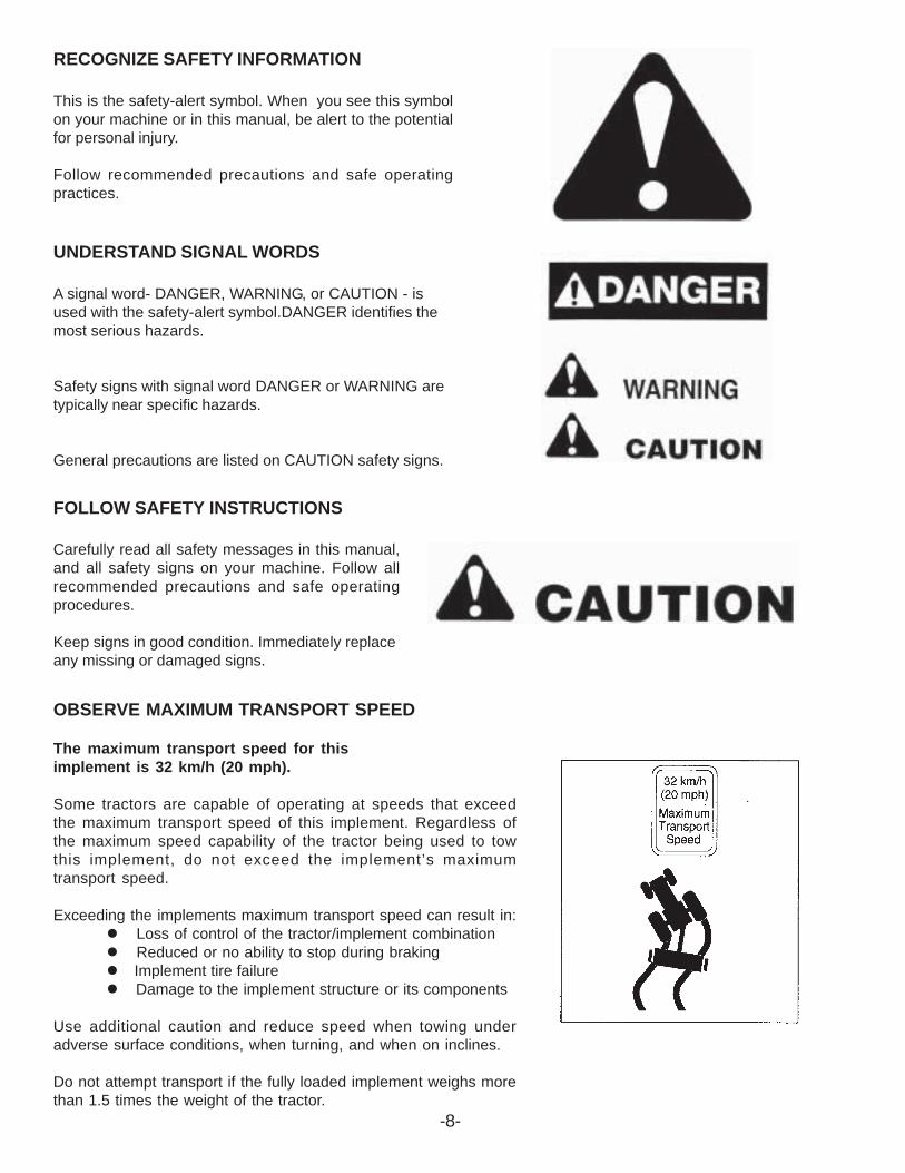
RECOGNIZE SAFETY INFORMATION
This is the safety-alert symbol. When you see this symbolon your machine or in this manual, be alert to the potentialfor personal injury.
Follow recommended precautions and safe operatingpractices.
UNDERSTAND SIGNAL WORDS
A signal word- DANGER, WARNING, or CAUTION - isused with the safety-alert symbol.DANGER identifies themost serious hazards.
Safety signs with signal word DANGER or WARNING aretypically near specific hazards.
General precautions are listed on CAUTION safety signs.
-8-
FOLLOW SAFETY INSTRUCTIONS
Carefully read all safety messages in this manual,and all safety signs on your machine. Follow allrecommended precautions and safe operatingprocedures.
Keep signs in good condition. Immediately replaceany missing or damaged signs.
OBSERVE MAXIMUM TRANSPORT SPEED
The maximum transport speed for thisimplement is 32 km/h (20 mph).
Some tractors are capable of operating at speeds that exceedthe maximum transport speed of this implement. Regardless ofthe maximum speed capability of the tractor being used to towthis implement, do not exceed the implement’s maximumtransport speed.
Exceeding the implements maximum transport speed can result in:" Loss of control of the tractor/implement combination" Reduced or no ability to stop during braking" Implement tire failure" Damage to the implement structure or its components
Use additional caution and reduce speed when towing underadverse surface conditions, when turning, and when on inclines.
Do not attempt transport if the fully loaded implement weighs morethan 1.5 times the weight of the tractor.

TRACTORSThis operators manual uses the term “Tractor” when identifying the power or the towing source.
W A R N I N GTO PREVENT SERIOUS INJURY OR DEATH
Study The Above Safety RulesATTENTION - BE ALERT - YOUR SAFETY IS INVOLVED
BEFORE YOU ATTEMPT TO OPERATE THIS EQUIPMENT, READ AND STUDY THE FOLLOWINGINFORMATION. IN ADDITION, MAKE SURE THAT EVERY INDIVIDUAL WHO OPERATES OR WORKSWITH THIS EQUIPMENT, WHETHER FAMILY MEMBER OR EMPLOYEE, IS FAMILIAR WITH THESESAFETY PRECAUTIONS.KNOW HOW TO STOP UNLOADING MECHANISM BEFORE STARTING IT.
If the machine becomes clogged, disengage the PTO. Stop the tractor engine, remove ignition key,and allow all mechanisms to stop before cleaning or working on the machine.Never allow riders in or on the machine.
Frontier always takes the operator and his safety into consideration and guards exposed movingparts for his protection. However, some areas cannot be guarded or shielded in order to assure properoperation. In addition, the operators manual and decals on the machine itself warn you of furtherdanger and should be read and observed closely.
-9-
hooked up.
DO NOT get off the tractor while the spreader is in operation.
DO NOT attempt to perform maintenance or repair with tractor running and PTO and hydraulic hoses
DO NOT step up on machine at any time.
NEVER manually feed material into the beaters.
DO NOT allow minors to operate or be near the machine.
DO NOT ALLOW PERSONNEL OTHER THAN THE QUALIFIED OPERATOR NEAR THE MACHINE.
Before starting tractor, be sure PTO shields turn freely and PTO is securely locked to tractor.
DO NOT clean, adjust, or lubricate the machine when any part is in operation.
Keep hands, feet, and clothing away from beaters when they are revolving.
Loose or floppy clothing should not be worn by the operator.
Be sure the machine is clear of people, tools, and other objects before engaging PTO or hydraulics.
DO NOT step over power take off shaft. Stay clear of PTO at all times.
NEVER start manure spreader until all guards and safety shields are secured in place.
NEVER operate spreader with a PTO speed Greater Than Recommended PTO RPM.
Stay clear of Hydraulic Lines. They may be under extreme pressure or heat.
When transporting on the highway, regularly clean the reflective tape and SMV decal at the rear of thespreader

-10-

-11-
1. Check for proper assembly and adjustment and make sure that all bolts are tightened. Securelyretighten after a few hours of operation, as bolts can loosen up on new machinery. Check wheel boltsupon delivery and periodically thereafter. Wheel bolts should be tightened at 85-95 ft./lbs. of torque.
2. Check the tires and inflate to the recommended pressure (11.00-22.5 tires to 40-60 PSI, 16.5-16.1tires to 35-40 PSI and 425-22.5 tires to 85 PSI).
3. Adjust the tractor hitch and attach the spreader to the tractor as described in the following sections. 4. Connect PTO from spreader to the tractor as described in the following sections. 5. Connect hydraulic hoses which operate augers from the spreader to a double acting valve on the
tractor. 6. Connect hydraulic hoses which control rear gates from the spreader to a double acting valve on
the tractor. 7. Connect electric auger speed control box to tractor power source, attach to a convenient place on
the tractor. 8. Connect transport light cord to tractor 7-pin connector. 9. Lubricate the machine completely and check the oil level of the gearbox. 10. Before loading spreader, run machine for several minutes to make sure that the spreader is
lubricated and operating properly.
OPERATION
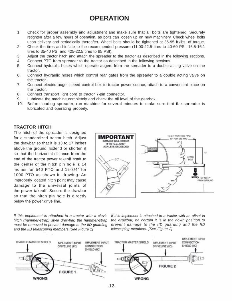
TRACTOR HITCHThe hitch of the spreader is designedfor a standardized tractor hitch. Adjustthe drawbar so that it is 13 to 17 inchesabove the ground. Extend or shorten itso that the horizontal distance from theend of the tractor power takeoff shaft tothe center of the hitch pin hole is 14inches for 540 PTO and 15-3/4” for1000 PTO as shown in drawing. Animproperly located hitch point may causedamage to the universal joints ofthe power takeoff. Secure the drawbarso that the hitch pin hole is directlybelow the power drive line.
If this implement is attached to a tractor with a clevishitch (hammer-strap) style drawbar, the hammer-strapmust be removed to prevent damage to the IID guardingand the IID telescoping members.[See Figure 1]
If this implement is attached to a tractor with an offset inthe drawbar, be certain it is in the down position toprevent damage to the IID guarding and the IIDtelescoping members. [See Figure 2]
-12-
-13-
OPERATION (Continued)
ATTACHING TO THE TRACTOR1. Fasten the spreader hitch to the tractor drawbar with a hitch pin with a safety locking device.
Use a 1” diameter hitch pin on the MS1337 and a 2” diameter hitch pin on the MS1354 & MS1368to pull spreader.
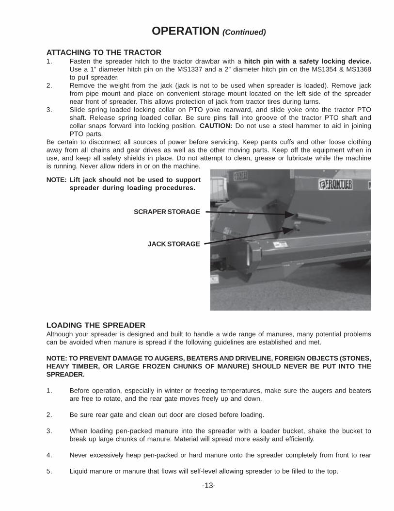
2. Remove the weight from the jack (jack is not to be used when spreader is loaded). Remove jackfrom pipe mount and place on convenient storage mount located on the left side of the spreadernear front of spreader. This allows protection of jack from tractor tires during turns.
3. Slide spring loaded locking collar on PTO yoke rearward, and slide yoke onto the tractor PTOshaft. Release spring loaded collar. Be sure pins fall into groove of the tractor PTO shaft andcollar snaps forward into locking position. CAUTION: Do not use a steel hammer to aid in joiningPTO parts.
Be certain to disconnect all sources of power before servicing. Keep pants cuffs and other loose clothingaway from all chains and gear drives as well as the other moving parts. Keep off the equipment when inuse, and keep all safety shields in place. Do not attempt to clean, grease or lubricate while the machineis running. Never allow riders in or on the machine.
NOTE: Lift jack should not be used to supportspreader during loading procedures.
LOADING THE SPREADERAlthough your spreader is designed and built to handle a wide range of manures, many potential problemscan be avoided when manure is spread if the following guidelines are established and met.
NOTE: TO PREVENT DAMAGE TO AUGERS, BEATERS AND DRIVELINE, FOREIGN OBJECTS (STONES,HEAVY TIMBER, OR LARGE FROZEN CHUNKS OF MANURE) SHOULD NEVER BE PUT INTO THESPREADER.
1. Before operation, especially in winter or freezing temperatures, make sure the augers and beatersare free to rotate, and the rear gate moves freely up and down.
2. Be sure rear gate and clean out door are closed before loading.
3. When loading pen-packed manure into the spreader with a loader bucket, shake the bucket tobreak up large chunks of manure. Material will spread more easily and efficiently.
4. Never excessively heap pen-packed or hard manure onto the spreader completely from front to rear
5. Liquid manure or manure that flows will self-level allowing spreader to be filled to the top.
SCRAPER STORAGE
JACK STORAGE
-14-
When transporting on the highway, connect power cord from tractor to spreader. Make surelights function properly. Regularly clean the reflective tape and SMV sign at the rear of thespreader.
SERVICINGBe certain to disconnect all sources of power before servicing. Keep pant cuffs and loose clothing awayfrom all chains and drives as well as the other moving parts. Keep off the equipment when is use, and keepall shields in place. Do not attempt to clean, grease or lubricate while the machine is running.Never allow riders in or on the machine.
OPERATION (Continued)UNLOADING AND SPREADINGTo spread a wide variety of manure types and prevent unnecessary stress on the driveline components,observe the following guidelines for each type of manure.
Liquid or Semi-Solid Manure (Self-Leveling)
1. Engage tractor PTO at as low an RPM as possible. Slowly throttle tractor up to bring PTO up to540 RPM.
2. Select desired ground speed and open discharge gate slowly to begin spreading.3. Engage appropriate lever of tractor hydraulics to operate augers.4. To achieve the desired coverage, adjust height of rear gate, speed of augers and/or ground speed.
Dry, Pen-Packed, or Manure Containing Long Straw or Hay
1. Engage tractor PTO as low an RPM as possible. Slowly throttle tractor up to bring PTO up to540 RPM.
2. Select desired ground speed and open rear gate completely to begin spreading.3. Engage appropriate lever of tractor hydraulics to operate augers. Begin unloading with augers
at slow speed.4. To achieve the desired coverage, adjust the speed of main augers and/or ground speed.
NOTE: IF IT BECOMES NECESSARY TO REVERSE AUGERS, ENGAGE TRACTOR HYDRAULICS SLOWLY.
OPERATION IN FREEZING WEATHER
1. Always allow spreader to empty completely.2. Disengage tractor PTO and hydraulics.3. Shut off tractor and remove ignition key.4. Allow all movement to stop before attempting to clean spreader.5. Scrape any remaining manure from inside and rear of spreader. Clean all manure from rear pan,
end of auger housings, and beater.6. Operate main augers to clean any remaining manure from inside spreader.7. Run rear gate up and down to sufficiently clean gate track.8. After following steps 3, 4 and 5, again check rear pan and beater area to be sure it is clean of all
manure.9. After hauling liquid or semi solid manure, place a small amount of straw in each auger housing at
the front of the spreader and operate spreader. This will wipe out excess liquid and help preventfreeze up of spreader.
10. Close clean out door at rear of spreader.11. Park spreader with rear gate approximately halfway open.
ADJUSTMENTSFAILURE TO FOLLOW THE RECOMMENDED ADJUSTMENTS WILL VOID WARRANTY
-15-
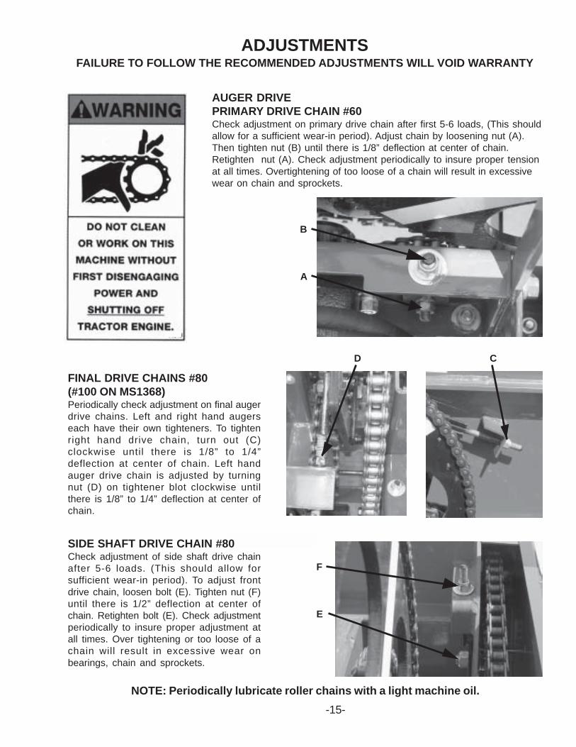
AUGER DRIVEPRIMARY DRIVE CHAIN #60Check adjustment on primary drive chain after first 5-6 loads, (This shouldallow for a sufficient wear-in period). Adjust chain by loosening nut (A).Then tighten nut (B) until there is 1/8” deflection at center of chain.Retighten nut (A). Check adjustment periodically to insure proper tensionat all times. Overtightening of too loose of a chain will result in excessivewear on chain and sprockets.
FINAL DRIVE CHAINS #80(#100 ON MS1368)Periodically check adjustment on final augerdrive chains. Left and right hand augerseach have their own tighteners. To tightenright hand drive chain, turn out (C)clockwise until there is 1/8” to 1/4”deflection at center of chain. Left handauger drive chain is adjusted by turningnut (D) on tightener blot clockwise untilthere is 1/8” to 1/4” deflection at center ofchain.
SIDE SHAFT DRIVE CHAIN #80Check adjustment of side shaft drive chainafter 5-6 loads. (This should allow forsufficient wear-in period). To adjust frontdrive chain, loosen bolt (E). Tighten nut (F)until there is 1/2” deflection at center ofchain. Retighten bolt (E). Check adjustmentperiodically to insure proper adjustment atall times. Over tightening or too loose of achain will result in excessive wear onbearings, chain and sprockets.
NOTE: Periodically lubricate roller chains with a light machine oil.
B
A
F
E
D C
-16-
ADJUSTMENTS (Continued)
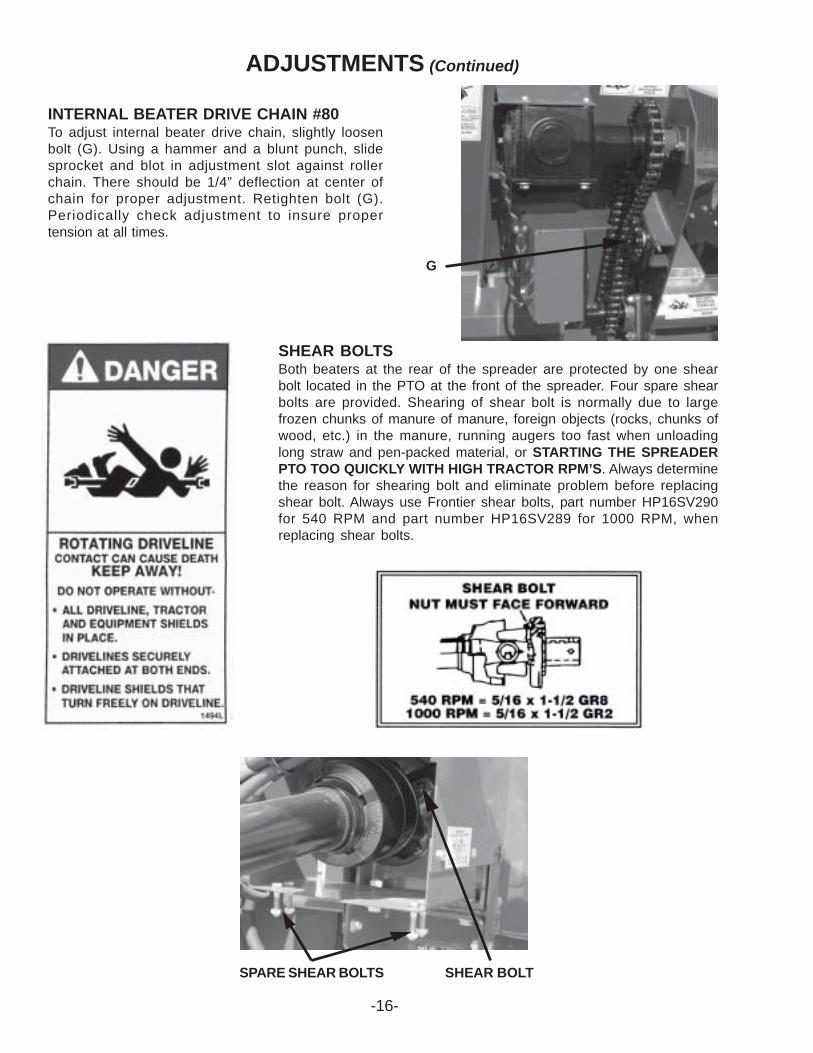
INTERNAL BEATER DRIVE CHAIN #80To adjust internal beater drive chain, slightly loosenbolt (G). Using a hammer and a blunt punch, slidesprocket and blot in adjustment slot against rollerchain. There should be 1/4” deflection at center ofchain for proper adjustment. Retighten bolt (G).Periodically check adjustment to insure propertension at all times.
SHEAR BOLTSBoth beaters at the rear of the spreader are protected by one shearbolt located in the PTO at the front of the spreader. Four spare shearbolts are provided. Shearing of shear bolt is normally due to largefrozen chunks of manure of manure, foreign objects (rocks, chunks ofwood, etc.) in the manure, running augers too fast when unloadinglong straw and pen-packed material, or STARTING THE SPREADERPTO TOO QUICKLY WITH HIGH TRACTOR RPM’S. Always determinethe reason for shearing bolt and eliminate problem before replacingshear bolt. Always use Frontier shear bolts, part number HP16SV290for 540 RPM and part number HP16SV289 for 1000 RPM, whenreplacing shear bolts.
G
SPARE SHEAR BOLTS SHEAR BOLT
ADJUSTMENTS (Continued)
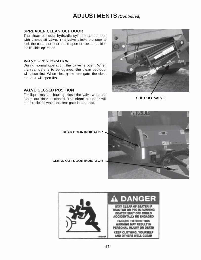
SPREADER CLEAN OUT DOORThe clean out door hydraulic cylinder is equippedwith a shut off valve. This valve allows the user tolock the clean out door in the open or closed positionfor flexible operation.
VALVE OPEN POSITIONDuring normal operation, the valve is open. Whenthe rear gate is to be opened, the clean out doorwill close first. When closing the rear gate, the cleanout door will open first.
VALVE CLOSED POSITIONFor liquid manure hauling, close the valve when theclean out door is closed. The clean out door willremain closed when the rear gate is operated.
SHUT OFF VALVE
REAR DOOR INDICATOR
CLEAN OUT DOOR INDICATOR
-17-
ADJUSTMENTS (Continued)
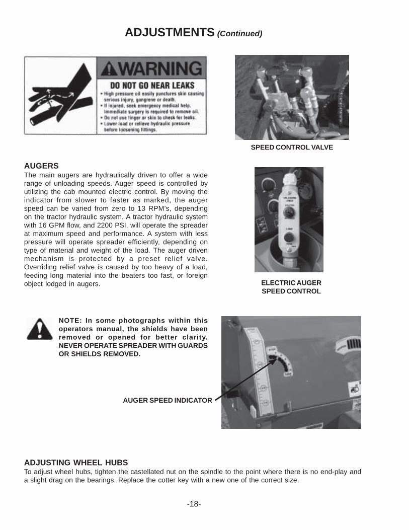
AUGERSThe main augers are hydraulically driven to offer a widerange of unloading speeds. Auger speed is controlled byutilizing the cab mounted electric control. By moving theindicator from slower to faster as marked, the augerspeed can be varied from zero to 13 RPM’s, dependingon the tractor hydraulic system. A tractor hydraulic systemwith 16 GPM flow, and 2200 PSI, will operate the spreaderat maximum speed and performance. A system with lesspressure will operate spreader efficiently, depending ontype of material and weight of the load. The auger drivenmechanism is protected by a preset relief valve.Overriding relief valve is caused by too heavy of a load,feeding long material into the beaters too fast, or foreignobject lodged in augers.
NOTE: In some photographs within thisoperators manual, the shields have beenremoved or opened for better clarity.NEVER OPERATE SPREADER WITH GUARDSOR SHIELDS REMOVED.
ADJUSTING WHEEL HUBSTo adjust wheel hubs, tighten the castellated nut on the spindle to the point where there is no end-play anda slight drag on the bearings. Replace the cotter key with a new one of the correct size.
AUGER SPEED INDICATOR
ELECTRIC AUGERSPEED CONTROL
SPEED CONTROL VALVE
-18-
LUBRICATION GUIDE
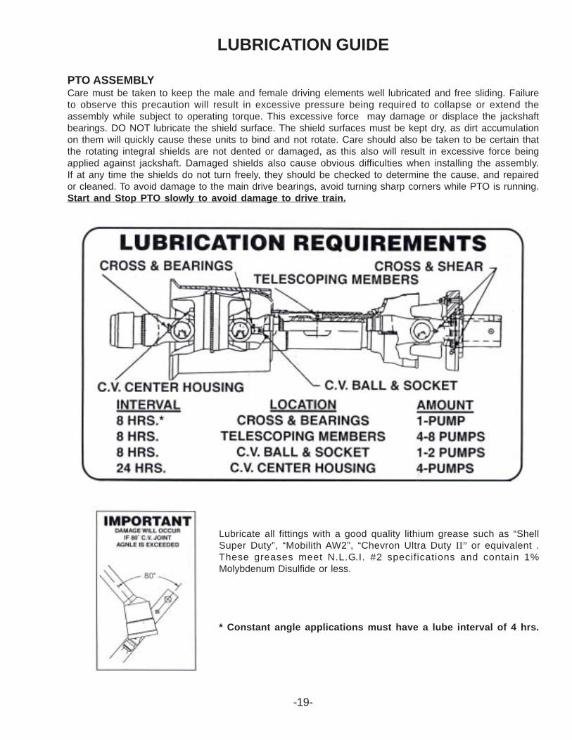
PTO ASSEMBLYCare must be taken to keep the male and female driving elements well lubricated and free sliding. Failureto observe this precaution will result in excessive pressure being required to collapse or extend theassembly while subject to operating torque. This excessive force may damage or displace the jackshaftbearings. DO NOT lubricate the shield surface. The shield surfaces must be kept dry, as dirt accumulationon them will quickly cause these units to bind and not rotate. Care should also be taken to be certain thatthe rotating integral shields are not dented or damaged, as this also will result in excessive force beingapplied against jackshaft. Damaged shields also cause obvious difficulties when installing the assembly.If at any time the shields do not turn freely, they should be checked to determine the cause, and repairedor cleaned. To avoid damage to the main drive bearings, avoid turning sharp corners while PTO is running.Start and Stop PTO slowly to avoid damage to drive train.
Lubricate all fittings with a good quality lithium grease such as “ShellSuper Duty”, “Mobilith AW2”, “Chevron Ultra Duty II” or equivalent .These greases meet N.L.G.I. #2 specifications and contain 1%Molybdenum Disulfide or less.
* Constant angle applications must have a lube interval of 4 hrs.
-19-
-20-
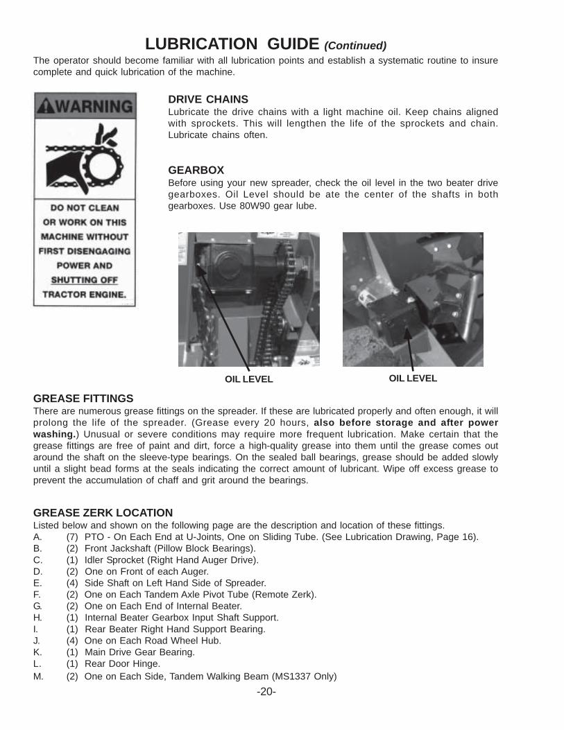
LUBRICATION GUIDE (Continued)The operator should become familiar with all lubrication points and establish a systematic routine to insurecomplete and quick lubrication of the machine.
GREASE FITTINGSThere are numerous grease fittings on the spreader. If these are lubricated properly and often enough, it willprolong the life of the spreader. (Grease every 20 hours, also before storage and after powerwashing.) Unusual or severe conditions may require more frequent lubrication. Make certain that thegrease fittings are free of paint and dirt, force a high-quality grease into them until the grease comes outaround the shaft on the sleeve-type bearings. On the sealed ball bearings, grease should be added slowlyuntil a slight bead forms at the seals indicating the correct amount of lubricant. Wipe off excess grease toprevent the accumulation of chaff and grit around the bearings.
GREASE ZERK LOCATIONListed below and shown on the following page are the description and location of these fittings.A. (7) PTO - On Each End at U-Joints, One on Sliding Tube. (See Lubrication Drawing, Page 16).B. (2) Front Jackshaft (Pillow Block Bearings).C. (1) Idler Sprocket (Right Hand Auger Drive).D. (2) One on Front of each Auger.E. (4) Side Shaft on Left Hand Side of Spreader.F. (2) One on Each Tandem Axle Pivot Tube (Remote Zerk).G. (2) One on Each End of Internal Beater.H. (1) Internal Beater Gearbox Input Shaft Support.I. (1) Rear Beater Right Hand Support Bearing.J. (4) One on Each Road Wheel Hub.K. (1) Main Drive Gear Bearing.L. (1) Rear Door Hinge.M. (2) One on Each Side, Tandem Walking Beam (MS1337 Only)
DRIVE CHAINSLubricate the drive chains with a light machine oil. Keep chains alignedwith sprockets. This will lengthen the life of the sprockets and chain.Lubricate chains often.
GEARBOXBefore using your new spreader, check the oil level in the two beater drivegearboxes. Oil Level should be ate the center of the shafts in bothgearboxes. Use 80W90 gear lube.
OIL LEVEL OIL LEVEL
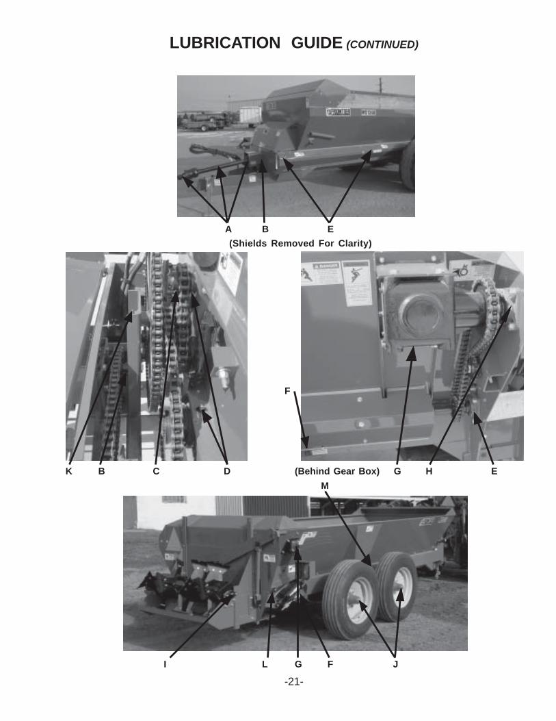
LUBRICATION GUIDE (CONTINUED)
-21-I L G F J
K B C D (Behind Gear Box) G H E
F
A B E
M
(Shields Removed For Clarity)
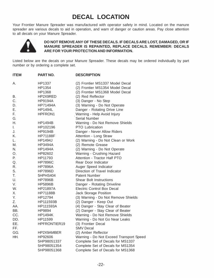
DECAL LOCATIONYour Frontier Manure Spreader was manufactured with operator safety in mind. Located on the manurespreader are various decals to aid in operation, and warn of danger or caution areas. Pay close attentionto all decals on your Manure Spreader.
DO NOT REMOVE ANY OF THESE DECALS. IF DECALS ARE LOST, DAMAGED, OR IFMANURE SPREADER IS REPAINTED, REPLACE DECALS. REMEMBER: DECALSARE FOR YOUR PROTECTION AND INFORMATION.
Listed below are the decals on your Manure Spreader. These decals may be ordered individually by partnumber or by ordering a complete set.
ITEM PART NO. DESCRIPTION
A. HP1337 (2) Frontier MS1337 Model DecalHP1354 (2) Frontier MS1354 Model DecalHP1368 (2) Frontier MS1368 Model Decal
B. HP2X9RED (2) Red ReflectorC. HP9194A (3) Danger - No StepD. HP71494A (3) Warning - Do Not OperateE. HP1494L Danger - Rotating Drive LineF. HPFRON1 Warning - Help Avoid InjuryG. Serial NumberH. HP1494B Warning - Do Not Remove ShieldsI. HP102196 PTO LubricationJ. HP9194B Danger - Never Allow RidersK. HP71188F Attention - Long StrawL. HP1494J (2) Warning - Do Not Clean or WorkM. HP3494A (2) Remote GreaseN. HP1494A (2) Warning - Do Not OperateO. HP82602 Warning - Crushing HazardP. HP11793 Attention - Tractor Half PTOQ. HP7896C Rear Door IndicatorR. HP7896A Auger Speed IndicatorS. HP7896D Direction of Travel IndicatorT. 5HPHS404 Patent NumberU. HP7896B Shear Bolt InstructionsV. HP5896B Danger - Rotating DrivelineW. HP21897A Electric Control Box DecalX. HP71188B Jack Storage PositionY. HP12794 (3) Warning - Do Not Remove ShieldsZ. HP111593B (2) Danger - Keep OutAA. HP111593A (4) Danger - Stay Clear of BeaterBB. HP9894 (2) Danger - Stay Clear of BeaterCC. HP1494K Warning - Do Not Remove ShieldsDD. HP11599 Warning - Do Not Go Near LeaksEE. HPFRONTIER19 (3) Frontier DecalFF. SMV DecalGG. HP2X9AMBER (2) Amber ReflectorHH. HP92606 Warning - Do Not Exceed Transport Speed
5HP98051337 Complete Set of Decals for MS13375HP98051354 Complete Set of Decals for MS13545HP98051368 Complete Set of Decals for MS1368
-22-
-23-
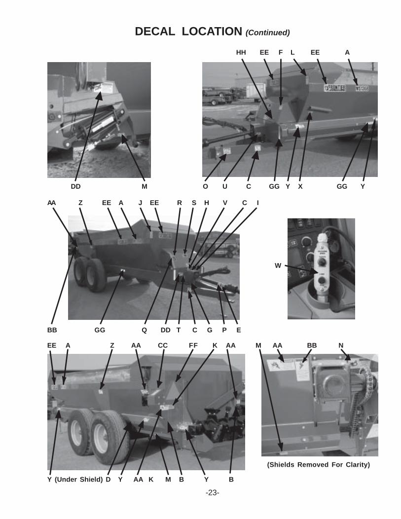
DECAL LOCATION (Continued)
(Shields Removed For Clarity)
EE A Z AA CC FF K AA M AA BB N
Y (Under Shield) D Y AA K M B Y B
W
DD M O U C GG Y X GG Y
HH EE F L EE A
BB GG Q DD T C G P E
AA Z EE A J EE R S H V C I
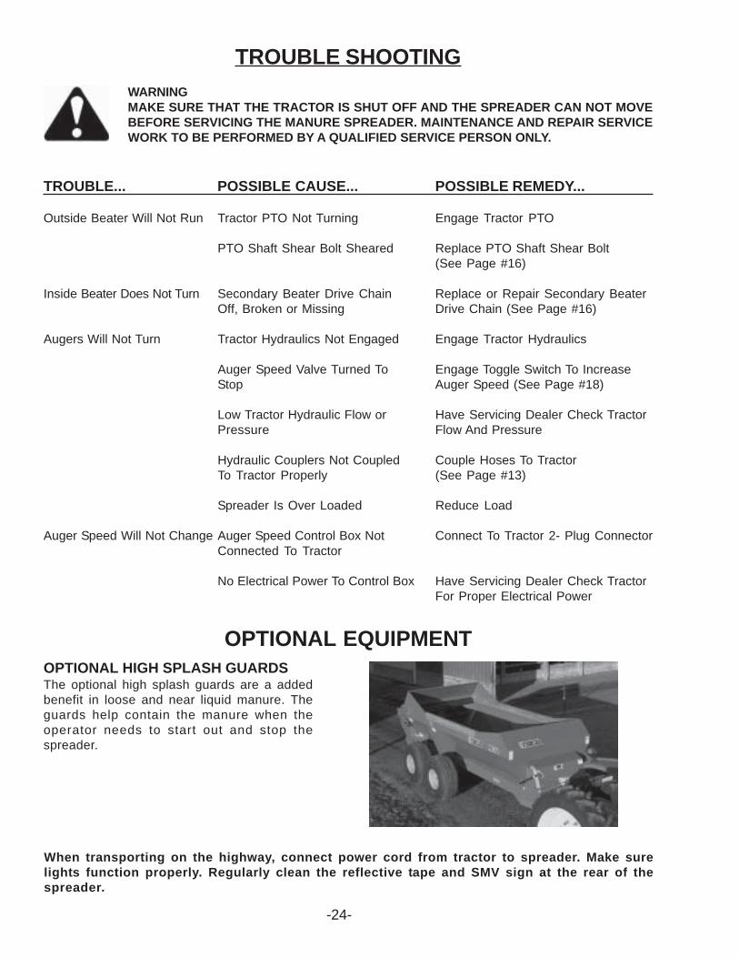
OPTIONAL HIGH SPLASH GUARDSThe optional high splash guards are a addedbenefit in loose and near liquid manure. Theguards help contain the manure when theoperator needs to start out and stop thespreader.
OPTIONAL EQUIPMENT
TROUBLE SHOOTINGWARNINGMAKE SURE THAT THE TRACTOR IS SHUT OFF AND THE SPREADER CAN NOT MOVEBEFORE SERVICING THE MANURE SPREADER. MAINTENANCE AND REPAIR SERVICEWORK TO BE PERFORMED BY A QUALIFIED SERVICE PERSON ONLY.
TROUBLE... POSSIBLE CAUSE... POSSIBLE REMEDY...
Outside Beater Will Not Run Tractor PTO Not Turning Engage Tractor PTO
PTO Shaft Shear Bolt Sheared Replace PTO Shaft Shear Bolt(See Page #16)
Inside Beater Does Not Turn Secondary Beater Drive Chain Replace or Repair Secondary BeaterOff, Broken or Missing Drive Chain (See Page #16)
Augers Will Not Turn Tractor Hydraulics Not Engaged Engage Tractor Hydraulics
Auger Speed Valve Turned To Engage Toggle Switch To IncreaseStop Auger Speed (See Page #18)
Low Tractor Hydraulic Flow or Have Servicing Dealer Check TractorPressure Flow And Pressure
Hydraulic Couplers Not Coupled Couple Hoses To TractorTo Tractor Properly (See Page #13)
Spreader Is Over Loaded Reduce Load
Auger Speed Will Not Change Auger Speed Control Box Not Connect To Tractor 2- Plug ConnectorConnected To Tractor
No Electrical Power To Control Box Have Servicing Dealer Check TractorFor Proper Electrical Power
When transporting on the highway, connect power cord from tractor to spreader. Make surelights function properly. Regularly clean the reflective tape and SMV sign at the rear of thespreader.
-24-

-25-
INSTRUCTIONS FOR ORDERING PARTS
All service parts should be ordered through your authorized Frontier dealer. He will be able to giveyou faster service if you will provide them with the following:
1. Model & Serial Number - Both can be located on the front center frame below the PTO shaft.
2. All references to left or right apply to the machine as viewed from the rear.
3. Parts should not be ordered from illustration only. Please order complete part number.
4. If your dealer has to order parts - give shipping instructions:
VIA truck - large pieces (please specify local truck lines)
VIA United Parcel Service (include full address)
PLEASE RECORD NUMBERS FOR YOUR UNIT FOR QUICK REFERENCE
ABOUT IMPROVEMENTS
FRONTIER IS CONTINUALLY STRIVING TO IMPROVE IT’S PRODUCTS
We must therefore, reserve the right to make improvements or changes whenever it becomes practical todo so, without incurring any obligation to make changes or additions to the equipment previously sold.
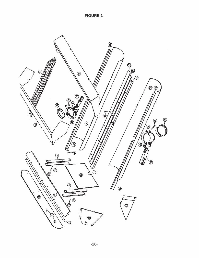
FIGURE 1
-26-
-27-
FIGURE 1FRONTIER MODEL MS1337, MS1354 & MS1368
TANK AND COMPONENT PARTS
ITEM MS1337 MS1354 MS1368 DESCRIPTION3. HP16SV6 “ HP33SV4 Auger Housing Poly4. HP16SV7 “ HP33SV5 Auger Wiper RH Front4A. HP16SV7A “ HP33SV5A Auger Wiper LH Front6. HP16SV9 “ “ Door Guide Poly7. HP16SV10 “ “ LH Door Guide8. HP12SV29 HP16SV11 “ Rubber Splash9. HP16SV12 “ “ Door10. HP16SV13 “ HP33SV6 Center Wipers11. HP16SV14 “ HP33SV7 Auger Poly Hold Down12. HP16SV15 “ HP33SV5A Auger Wiper RH Back12A. HP16SV15A “ HP33SV5 Auger Wiper LH Back13. HP16SV44 HP16SV263 HP33SV87 RH Corner Filler * HP16SV266 HP16SV264 HP33SV88 LH Corner Filler14. HP16SV18 “ “ RH Door Guide15. HP16SV19 “ “ 1/2” x 2” Bolt CTR Sunk16. - - HP33SV13 Back Splash Extension17. HP23N194 “ “ 1/2” x 2” Bolt GR. 518. HP16SV21 “ “ 3/8” x 1-1/2” Carr. Bolt GR.519. HPBFR247 “ “ 3/8” x 1” Carr. Bolt GR. 520. - HP16SV216 HP33SV10 Front Splash21. - HP16SV217 - Wood Rails * - - HP33SV11 Wood Rail * - - HP33SV110 Protective Angle Rail22. HP12SV30 HP16SV220 - Strap23. HP12SV31 - - Back Splash Poly24. HP12SV32 - - Back Splash Poly Washer25. HP12SV40 - - Back Splash Gusset RH * HP12SV42 - - Back Splash Gusset LH27. HP16SV404 “ “ Poly Bearing28. HP16SV405 “ “ Auger Bearing Post29. HP16SV406 “ “ Auger Bearing Cap A30. HP16SV407 “ “ Auger Bearing Cap B31. HP16SV408 “ “ Pin * HP16SV409 “ “ Shim (As Needed)NOT SHOWN:OPTIONAL HIGH SPLASH GUARD * HP16SV359 HP16SV360 - High-Back Splash Extension * HP16SV369 HP16SV363 - High-Front Splash ExtensionNOTE: * (MEANS NOT SHOWN
“ (MEANS SAME AS PRECEDING PART NUMBER) - (MEANS NOT USED ON THIS MODEL)
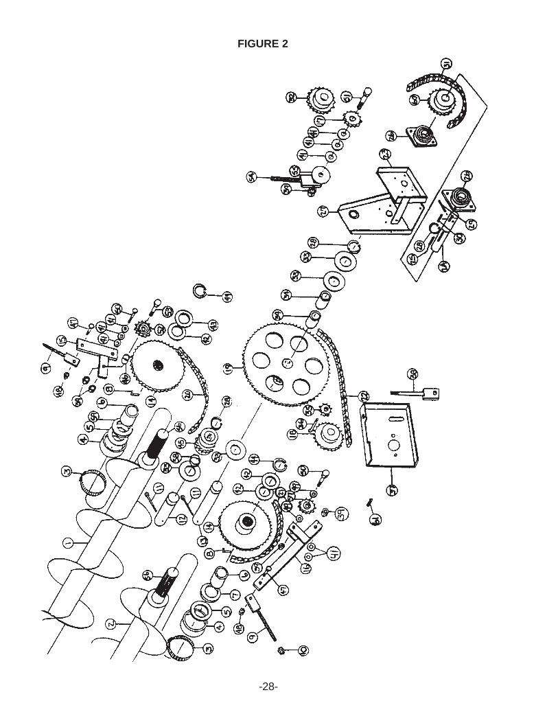
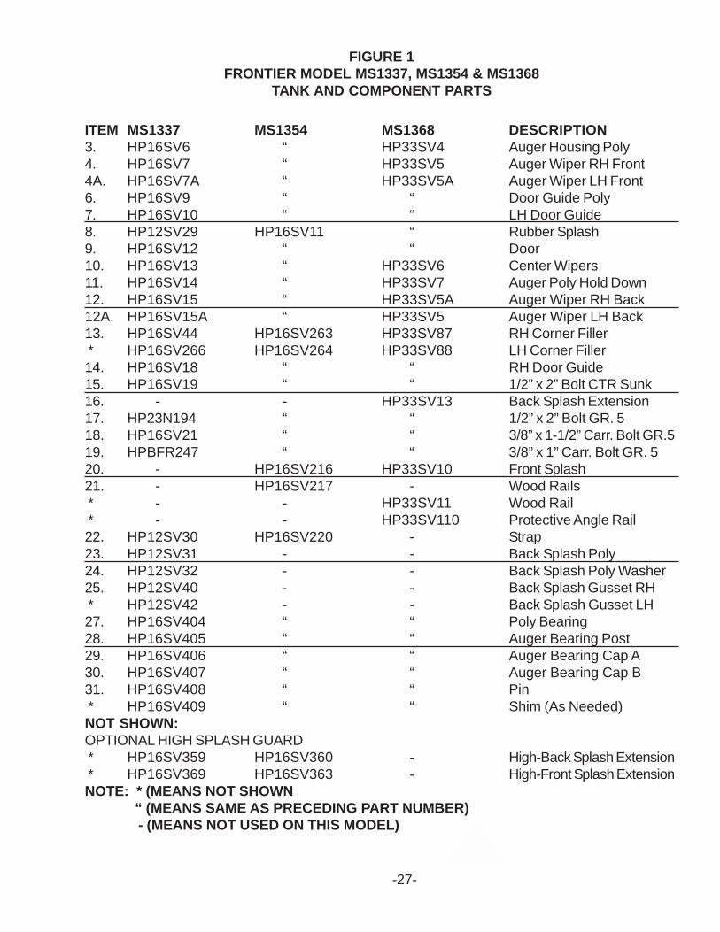
FIGURE 2
-28-
-29-
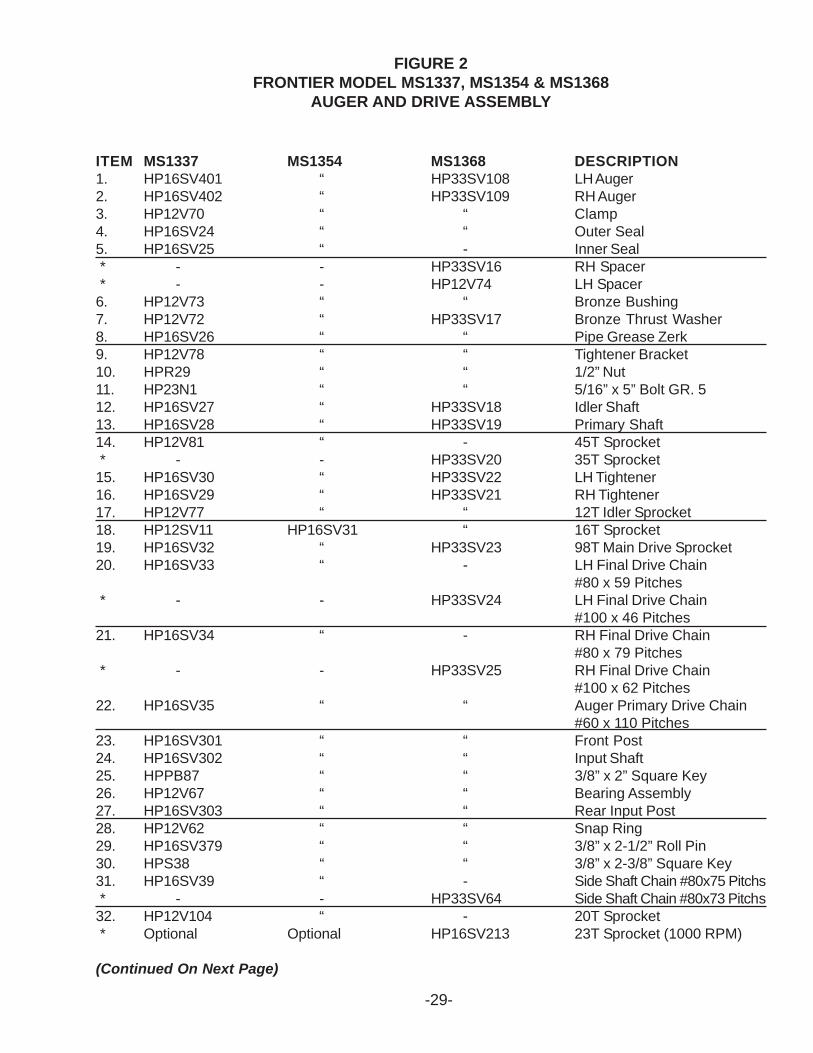
FIGURE 2FRONTIER MODEL MS1337, MS1354 & MS1368
AUGER AND DRIVE ASSEMBLY
ITEM MS1337 MS1354 MS1368 DESCRIPTION1. HP16SV401 “ HP33SV108 LH Auger2. HP16SV402 “ HP33SV109 RH Auger3. HP12V70 “ “ Clamp4. HP16SV24 “ “ Outer Seal5. HP16SV25 “ - Inner Seal * - - HP33SV16 RH Spacer * - - HP12V74 LH Spacer6. HP12V73 “ “ Bronze Bushing7. HP12V72 “ HP33SV17 Bronze Thrust Washer8. HP16SV26 “ “ Pipe Grease Zerk9. HP12V78 “ “ Tightener Bracket10. HPR29 “ “ 1/2” Nut11. HP23N1 “ “ 5/16” x 5” Bolt GR. 512. HP16SV27 “ HP33SV18 Idler Shaft13. HP16SV28 “ HP33SV19 Primary Shaft14. HP12V81 “ - 45T Sprocket * - - HP33SV20 35T Sprocket15. HP16SV30 “ HP33SV22 LH Tightener16. HP16SV29 “ HP33SV21 RH Tightener17. HP12V77 “ “ 12T Idler Sprocket18. HP12SV11 HP16SV31 “ 16T Sprocket19. HP16SV32 “ HP33SV23 98T Main Drive Sprocket20. HP16SV33 “ - LH Final Drive Chain
#80 x 59 Pitches * - - HP33SV24 LH Final Drive Chain
#100 x 46 Pitches21. HP16SV34 “ - RH Final Drive Chain
#80 x 79 Pitches * - - HP33SV25 RH Final Drive Chain
#100 x 62 Pitches22. HP16SV35 “ “ Auger Primary Drive Chain
#60 x 110 Pitches23. HP16SV301 “ “ Front Post24. HP16SV302 “ “ Input Shaft25. HPPB87 “ “ 3/8” x 2” Square Key26. HP12V67 “ “ Bearing Assembly27. HP16SV303 “ “ Rear Input Post28. HP12V62 “ “ Snap Ring29. HP16SV379 “ “ 3/8” x 2-1/2” Roll Pin30. HPS38 “ “ 3/8” x 2-3/8” Square Key31. HP16SV39 “ - Side Shaft Chain #80x75 Pitchs * - - HP33SV64 Side Shaft Chain #80x73 Pitchs32. HP12V104 “ - 20T Sprocket * Optional Optional HP16SV213 23T Sprocket (1000 RPM)
(Continued On Next Page)
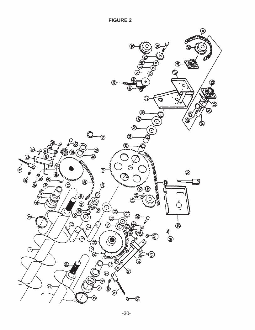
FIGURE 2
-30-
-31-
FIGURE 2FRONTIER MODEL MS1337, MS1354 & MS1368
AUGER AND DRIVE ASSEMBLY
ITEM MS1337 MS1354 MS1368 DESCRIPTION33. HP16SV40 “ “ Shim34. HP16SV41 “ “ Bronze Bushing
1-3/4”OD x 1-1/2”ID x 2-3/8”35. HP12N42 “ “ 15T Sprocket36. HP16SV91 “ “ 1/2” x 3-3/4” Bolt GR. 537. HP16SV42 “ “ Motor Mount38. HP16SV43 “ “ Tightener Bracket39. HPHE7 “ “ 3/4” Nut41. HPT73 “ “ Shim42. HP16SV45 “ “ Shim 3/16”43. HP16SV46 “ “ Shim 1/4”44. HPB17F “ “ Snap Ring45. HP16SV47 “ - 12T Idler Sprocket * - - HP33SV27 9T Idler Sprocket46. HP16SV48 “ “ Spacer47. HP12V45 “ “ 1/2” x 1-1/2” Bolt GR. 548. HP9S17 “ “ 1/2” Lock Nut49. HP16SV49 “ “ Shim 1/16”50. HPHE8 “ “ 3/4” x 2-1/4” Bolt GR. 551. HP16SV50 “ “ 3/4” x 2-1/2” Bolt GR. 552. HP16SV328 “ - Reinforced 12T Idler Sprocket * - - HP33SV1 Reinforced 9T Idler Sprocket53. HP16SV202 “ “ 3/4” x 3-3/4” Bolt GR. 554. HP16SV204 “ “ Tightener Mount55. HP16SV211 “ “ Spacer56. HP16SV222 “ HP33SV86 Splined Shaft w/Auger End57. HP12V77 “ - 12T Idler Sprocket * - - HP33SV30 9T Idler Sprocket58. - - HP33SV29 Reverse Idler Spacer59. HP12V72 “ HP33SV17 Bronze Thrust Washer * - - HP33SV16 LH Auger Spacer60. HP12V104 “ - 20T Sprocket * Optional Optional HPST11 13T Sprocket (1000 RPM)61. HP5B10 - - 1/4” x 1” Woodruff Key * - HPG23 “ 5/16” x 1-3/8” Square KeyNOTE: * (MEANS NOT SHOWN)
“(MEANS SAME AS PRECEDING PART NUMBER) - (MEANS NOT USED ON THIS MODEL)
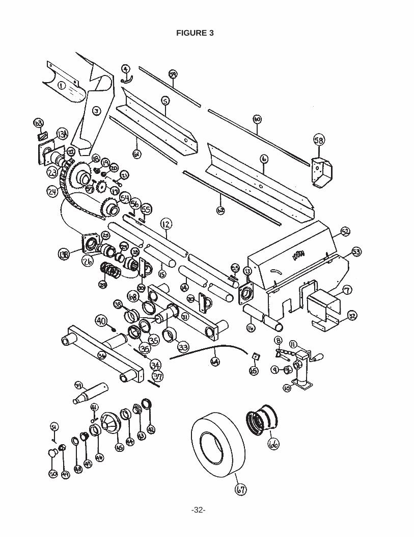
FIGURE 3
-32-
-33-
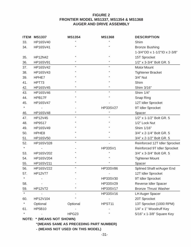
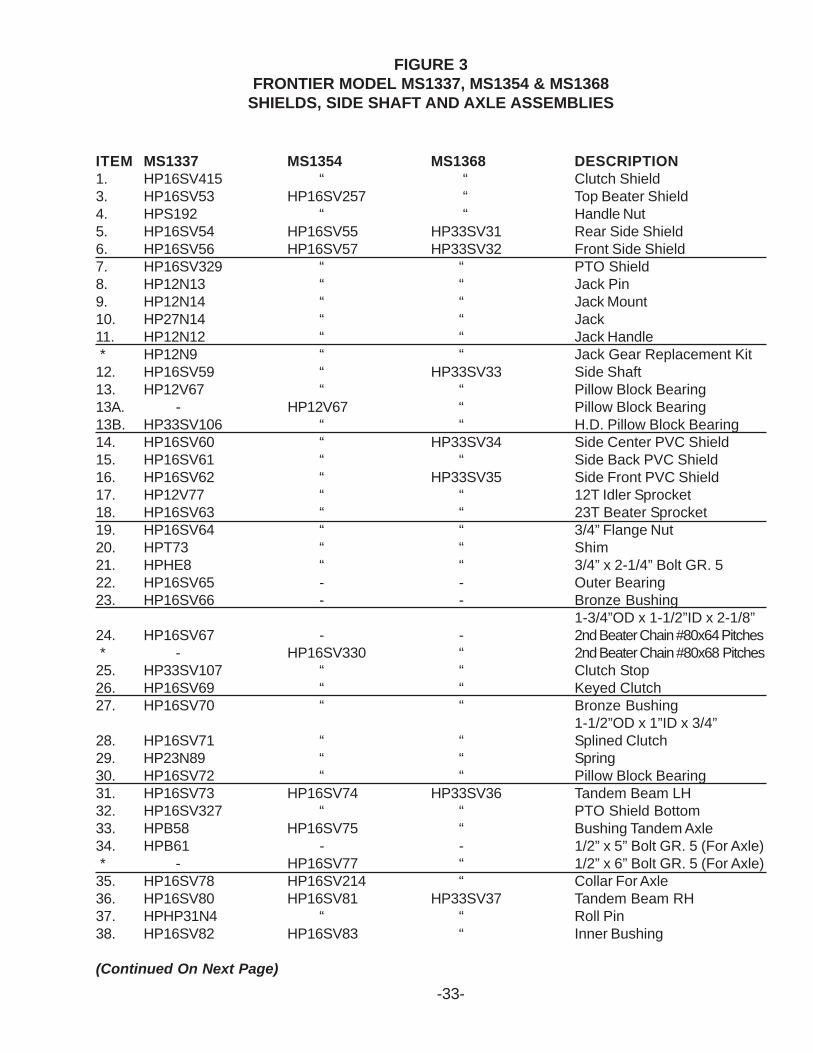
FIGURE 3FRONTIER MODEL MS1337, MS1354 & MS1368
SHIELDS, SIDE SHAFT AND AXLE ASSEMBLIES
ITEM MS1337 MS1354 MS1368 DESCRIPTION1. HP16SV415 “ “ Clutch Shield3. HP16SV53 HP16SV257 “ Top Beater Shield4. HPS192 “ “ Handle Nut5. HP16SV54 HP16SV55 HP33SV31 Rear Side Shield6. HP16SV56 HP16SV57 HP33SV32 Front Side Shield7. HP16SV329 “ “ PTO Shield8. HP12N13 “ “ Jack Pin9. HP12N14 “ “ Jack Mount10. HP27N14 “ “ Jack11. HP12N12 “ “ Jack Handle * HP12N9 “ “ Jack Gear Replacement Kit12. HP16SV59 “ HP33SV33 Side Shaft13. HP12V67 “ “ Pillow Block Bearing13A. - HP12V67 “ Pillow Block Bearing13B. HP33SV106 “ “ H.D. Pillow Block Bearing14. HP16SV60 “ HP33SV34 Side Center PVC Shield15. HP16SV61 “ “ Side Back PVC Shield16. HP16SV62 “ HP33SV35 Side Front PVC Shield17. HP12V77 “ “ 12T Idler Sprocket18. HP16SV63 “ “ 23T Beater Sprocket19. HP16SV64 “ “ 3/4” Flange Nut20. HPT73 “ “ Shim21. HPHE8 “ “ 3/4” x 2-1/4” Bolt GR. 522. HP16SV65 - - Outer Bearing23. HP16SV66 - - Bronze Bushing
1-3/4”OD x 1-1/2”ID x 2-1/8”24. HP16SV67 - - 2nd Beater Chain #80x64 Pitches * - HP16SV330 “ 2nd Beater Chain #80x68 Pitches25. HP33SV107 “ “ Clutch Stop26. HP16SV69 “ “ Keyed Clutch27. HP16SV70 “ “ Bronze Bushing
1-1/2”OD x 1”ID x 3/4”28. HP16SV71 “ “ Splined Clutch29. HP23N89 “ “ Spring30. HP16SV72 “ “ Pillow Block Bearing31. HP16SV73 HP16SV74 HP33SV36 Tandem Beam LH32. HP16SV327 “ “ PTO Shield Bottom33. HPB58 HP16SV75 “ Bushing Tandem Axle34. HPB61 - - 1/2” x 5” Bolt GR. 5 (For Axle) * - HP16SV77 “ 1/2” x 6” Bolt GR. 5 (For Axle)35. HP16SV78 HP16SV214 “ Collar For Axle36. HP16SV80 HP16SV81 HP33SV37 Tandem Beam RH37. HPHP31N4 “ “ Roll Pin38. HP16SV82 HP16SV83 “ Inner Bushing
(Continued On Next Page)
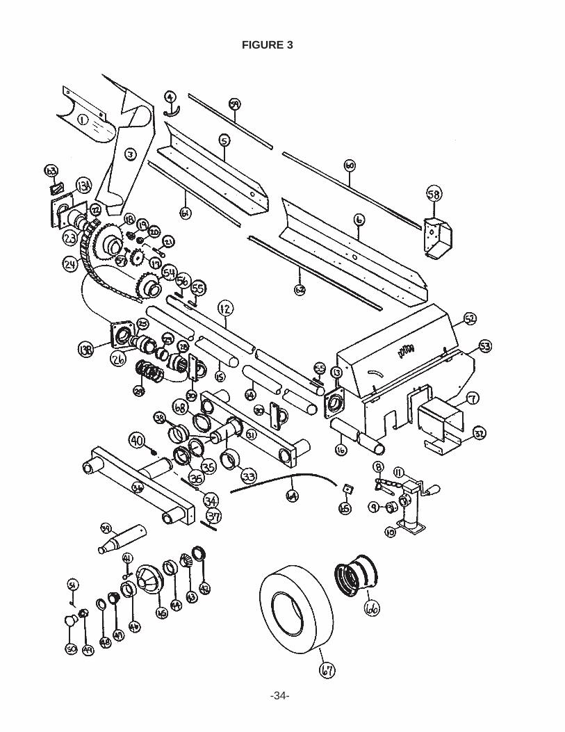
FIGURE 3
-34-
-35-
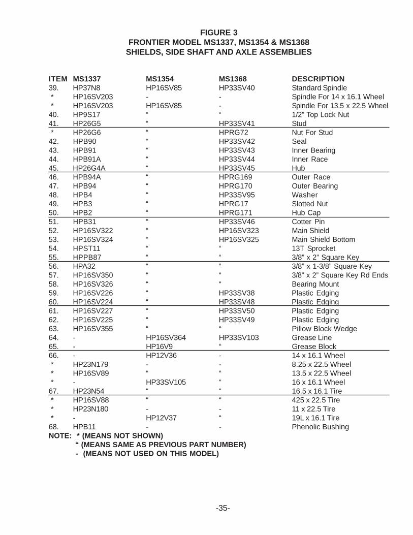
FIGURE 3FRONTIER MODEL MS1337, MS1354 & MS1368
SHIELDS, SIDE SHAFT AND AXLE ASSEMBLIES
ITEM MS1337 MS1354 MS1368 DESCRIPTION39. HP37N8 HP16SV85 HP33SV40 Standard Spindle * HP16SV203 - - Spindle For 14 x 16.1 Wheel * HP16SV203 HP16SV85 - Spindle For 13.5 x 22.5 Wheel40. HP9S17 “ “ 1/2” Top Lock Nut41. HP26G5 “ HP33SV41 Stud * HP26G6 “ HPRG72 Nut For Stud42. HPB90 “ HP33SV42 Seal43. HPB91 “ HP33SV43 Inner Bearing44. HPB91A “ HP33SV44 Inner Race45. HP26G4A “ HP33SV45 Hub46. HPB94A “ HPRG169 Outer Race47. HPB94 “ HPRG170 Outer Bearing48. HPB4 “ HP33SV95 Washer49. HPB3 “ HPRG17 Slotted Nut50. HPB2 “ HPRG171 Hub Cap51. HPB31 “ HP33SV46 Cotter Pin52. HP16SV322 “ HP16SV323 Main Shield53. HP16SV324 “ HP16SV325 Main Shield Bottom54. HPST11 “ “ 13T Sprocket55. HPPB87 “ “ 3/8” x 2” Square Key56. HPA32 “ “ 3/8” x 1-3/8” Square Key57. HP16SV350 “ “ 3/8” x 2” Square Key Rd Ends58. HP16SV326 “ “ Bearing Mount59. HP16SV226 “ HP33SV38 Plastic Edging60. HP16SV224 “ HP33SV48 Plastic Edging61. HP16SV227 “ HP33SV50 Plastic Edging62. HP16SV225 “ HP33SV49 Plastic Edging63. HP16SV355 “ “ Pillow Block Wedge64. - HP16SV364 HP33SV103 Grease Line65. - HP16V9 “ Grease Block66. - HP12V36 - 14 x 16.1 Wheel * HP23N179 - - 8.25 x 22.5 Wheel * HP16SV89 “ “ 13.5 x 22.5 Wheel * - HP33SV105 “ 16 x 16.1 Wheel67. HP23N54 “ “ 16.5 x 16.1 Tire * HP16SV88 “ “ 425 x 22.5 Tire * HP23N180 - - 11 x 22.5 Tire * - HP12V37 “ 19L x 16.1 Tire68. HPB11 - - Phenolic BushingNOTE: * (MEANS NOT SHOWN)
“ (MEANS SAME AS PREVIOUS PART NUMBER) - (MEANS NOT USED ON THIS MODEL)
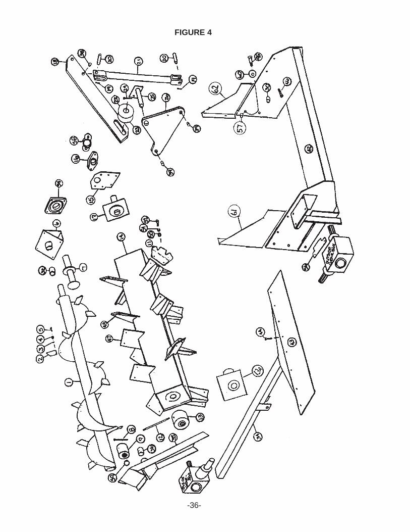
FIGURE 4
-36-
-37-
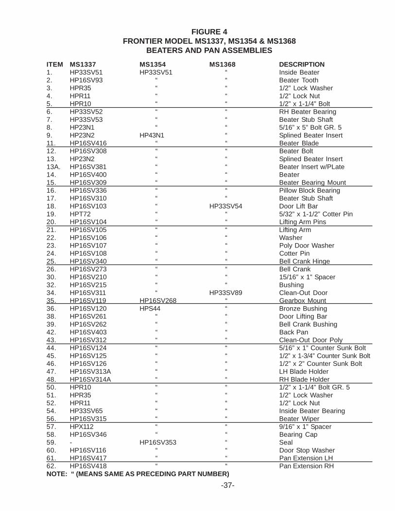
FIGURE 4FRONTIER MODEL MS1337, MS1354 & MS1368
BEATERS AND PAN ASSEMBLIES
ITEM MS1337 MS1354 MS1368 DESCRIPTION1. HP33SV51 HP33SV51 “ Inside Beater2. HP16SV93 “ “ Beater Tooth3. HPR35 “ “ 1/2” Lock Washer4. HPR11 “ “ 1/2” Lock Nut5. HPR10 “ “ 1/2” x 1-1/4” Bolt6. HP33SV52 “ “ RH Beater Bearing7. HP33SV53 “ “ Beater Stub Shaft8. HP23N1 “ “ 5/16” x 5” Bolt GR. 59. HP23N2 HP43N1 “ Splined Beater Insert11. HP16SV416 “ “ Beater Blade12. HP16SV308 “ “ Beater Bolt13. HP23N2 “ “ Splined Beater Insert13A. HP16SV381 “ “ Beater Insert w/PLate14. HP16SV400 “ “ Beater15. HP16SV309 “ “ Beater Bearing Mount16. HP16SV336 “ “ Pillow Block Bearing17. HP16SV310 “ “ Beater Stub Shaft18. HP16SV103 “ HP33SV54 Door Lift Bar19. HPT72 “ “ 5/32” x 1-1/2” Cotter Pin20. HP16SV104 “ “ Lifting Arm Pins21. HP16SV105 “ “ Lifting Arm22. HP16SV106 “ “ Washer23. HP16SV107 “ “ Poly Door Washer24. HP16SV108 “ “ Cotter Pin25. HP16SV340 “ “ Bell Crank Hinge26. HP16SV273 “ “ Bell Crank30. HP16SV210 “ “ 15/16” x 1” Spacer32. HP16SV215 “ “ Bushing34. HP16SV311 “ HP33SV89 Clean-Out Door35. HP16SV119 HP16SV268 “ Gearbox Mount36. HP16SV120 HPS44 “ Bronze Bushing38. HP16SV261 “ “ Door Lifting Bar39. HP16SV262 “ “ Bell Crank Bushing42. HP16SV403 “ “ Back Pan43. HP16SV312 “ “ Clean-Out Door Poly44. HP16SV124 “ “ 5/16” x 1” Counter Sunk Bolt45. HP16SV125 “ “ 1/2” x 1-3/4” Counter Sunk Bolt46. HP16SV126 “ “ 1/2” x 2” Counter Sunk Bolt47. HP16SV313A “ “ LH Blade Holder48. HP16SV314A “ “ RH Blade Holder50. HPR10 “ “ 1/2” x 1-1/4” Bolt GR. 551. HPR35 “ “ 1/2” Lock Washer52. HPR11 “ “ 1/2” Lock Nut54. HP33SV65 “ “ Inside Beater Bearing56. HP16SV315 “ “ Beater Wiper57. HPX112 “ “ 9/16” x 1” Spacer58. HP16SV346 “ “ Bearing Cap59. - HP16SV353 “ Seal60. HP16SV116 “ “ Door Stop Washer61. HP16SV417 “ “ Pan Extension LH62. HP16SV418 “ “ Pan Extension RHNOTE: “ (MEANS SAME AS PRECEDING PART NUMBER)
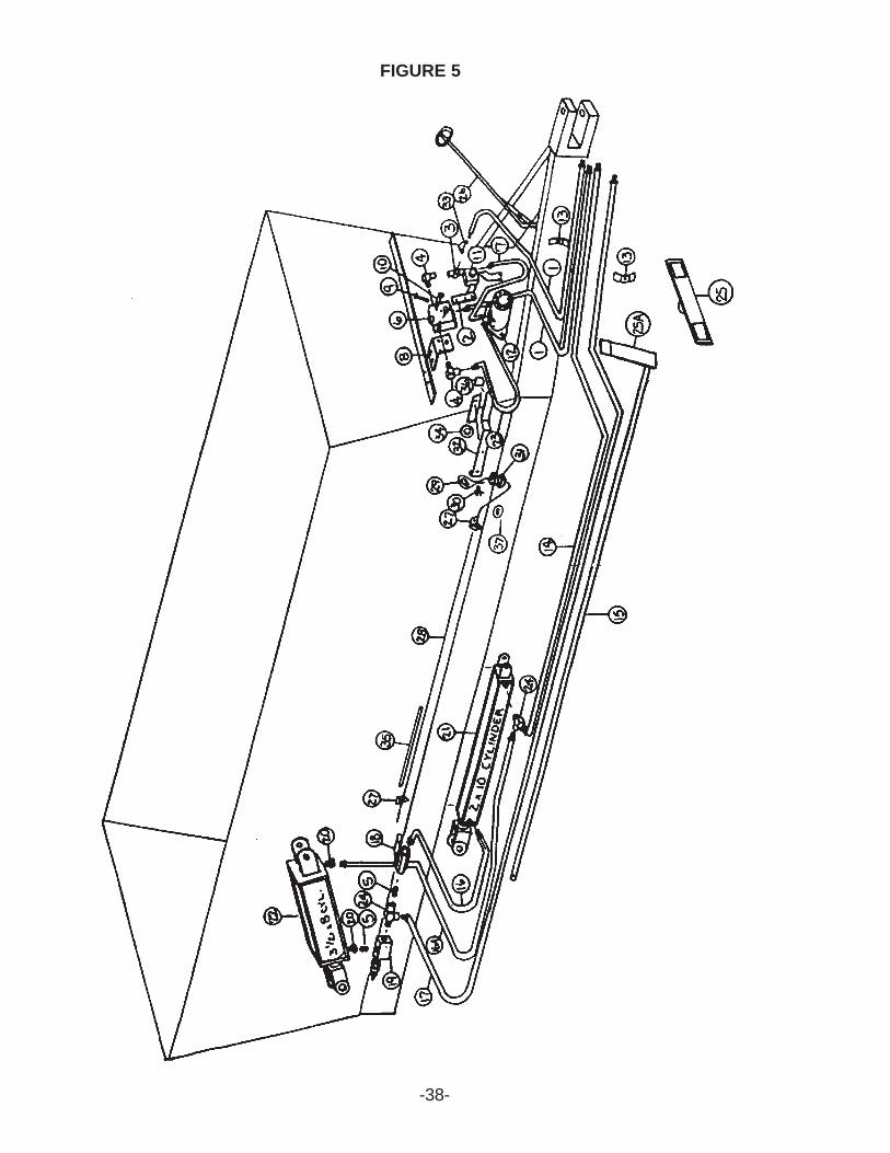
FIGURE 5
-38-
-39-
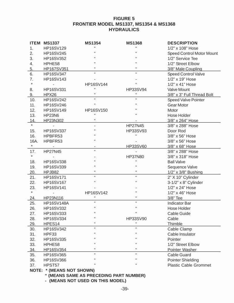
FIGURE 5FRONTIER MODEL MS1337, MS1354 & MS1368
HYDRAULICS
ITEM MS1337 MS1354 MS1368 DESCRIPTION1. HP16SV129 “ “ 1/2” x 108” Hose2. HP16SV245 “ “ Speed Control Motor Mount3. HP16SV352 “ “ 1/2” Service Tee4. HPHE58 “ “ 1/2” Street Elbow5. HP167SV351 “ “ 3/8” Male Coupling6. HP16SV347 “ “ Speed Control Valve7. HP16SV143 - - 1/2” x 19” Hose * - HP16SV144 “ 1/2” x 41” Hose8. HP16SV331 “ HP33SV94 Valve Mount9. HPX26 “ “ 3/8” x 3” Full Thread Bolt10. HP16SV242 “ “ Speed Valve Pointer11. HP16SV246 “ “ Gear Motor12. HP16SV149 HP16SV150 “ Motor13. HP23N6 “ “ Hose Holder14. HP23N302 “ - 3/8” x 264” Hose * - - HP27N45 3/8” x 288” Hose15. HP16SV337 “ HP33SV93 Door Rod16. HPBFR53 “ “ 3/8” x 56” Hose16A. HPBFR53 “ - 3/8” x 56” Hose * - - HP33SV60 3/8” x 68” Hose17. HP27N45 “ - 3/8” x 288” Hose * - - HP37N80 3/8” x 318” Hose18. HP16SV338 “ “ Ball Valve19. HP16SV339 “ “ Sequence Valve20. HPJB82 “ “ 1/2” x 3/8” Bushing21. HP16SV171 “ “ 2” X 10” Cylinder22. HP16SV167 “ “ 3-1/2” x 8” Cylinder23. HP16SV141 - - 1/2” x 24” Hose * - HP16SV142 “ 1/2” x 46” Hose24. HP23N116 “ “ 3/8” Tee25. HP16SV148A “ “ Indicator Bar26. HP16SV332 “ “ Hose Holder27. HP16SV333 “ “ Cable Guide28. HP16SV334 “ HP33SV90 Cable29. HPES14 “ “ Thimble30. HP16SV342 “ “ Cable Clamp31. HPF33 “ “ Cable Insulator32. HP16SV335 “ “ Pointer33. HPHE58 “ “ 1/2” Street Elbow34. HP16SV354 “ “ Pointer Washer35. HP16SV365 “ “ Cable Guard36. HP16SV366 “ “ Pointer Shielding37. HPST57 “ “ Plastic Cable GrommetNOTE: * (MEANS NOT SHOWN)
“ (MEANS SAME AS PRECEDING PART NUMBER) - (MEANS NOT USED ON THIS MODEL)
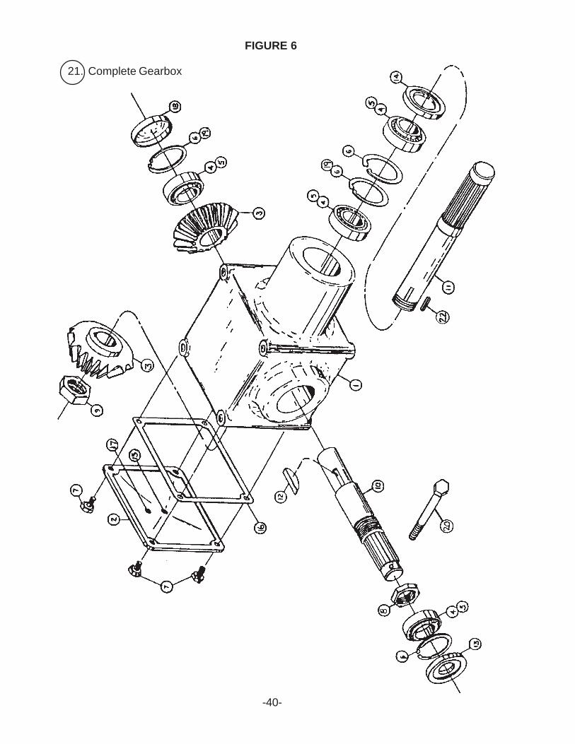
FIGURE 6
-40-
21. Complete Gearbox
-41-
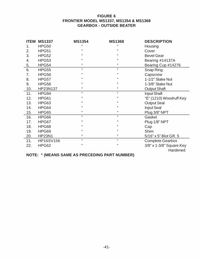
FIGURE 6FRONTIER MODEL MS1337, MS1354 & MS1368
GEARBOX - OUTSIDE BEATER
ITEM MS1337 MS1354 MS1368 DESCRIPTION1. HPG50 “ “ Housing2. HPG51 “ “ Cover3. HPG52 “ “ Bevel Gear4. HPG53 “ “ Bearing #14137A5. HPG54 “ “ Bearing Cup #142766. HPG55 “ “ Snap Ring7. HPG56 “ “ Capscrew8. HPG57 “ “ 1-1/2” Stake Nut9. HPG58 “ “ 1-3/8” Stake Nut10. HP23N137 “ “ Output Shaft11. HPG94 “ “ Input Shaft12. HPG61 “ “ “E” (1210) Woodruff Key13. HPG63 “ “ Output Seal14. HPG64 “ “ Input Seal15. HPG65 “ “ Plug 3/8” NPT16. HPG66 “ “ Gasket17. HPG67 “ “ Plug 1/8” NPT18. HPG68 “ “ Cap19. HPG69 “ “ Shim20. HP23N1 “ “ 5/16” x 5” Blot GR. 521. HP16SV156 “ “ Complete Gearbox22. HPG62 “ “ 3/8” x 1-3/8” Square Key
HardenedNOTE: “ (MEANS SAME AS PRECEDING PART NUMBER)
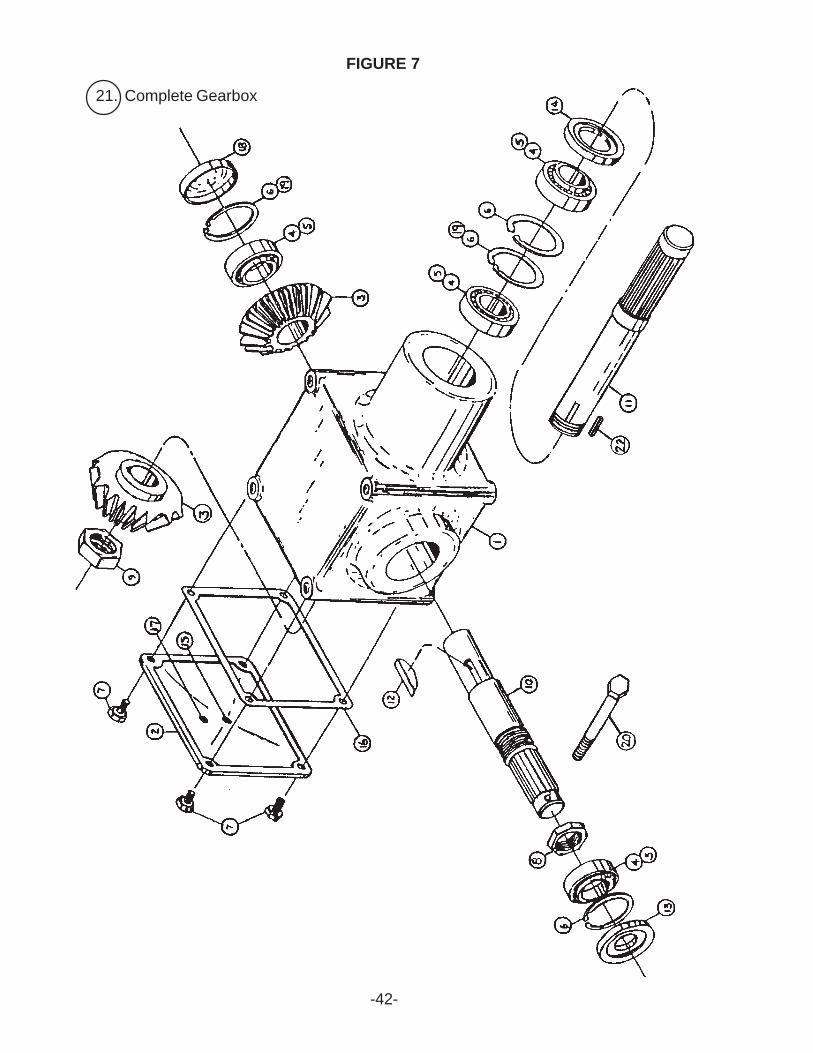
FIGURE 7
-42-
21. Complete Gearbox

-43-
FIGURE 7FRONTIER MODEL MS1337
GEARBOX - INSIDE BEATER
ITEM MS1337 DESCRIPTION1. HPG50 Housing2. HPG51 Cover3. HPG52 Bevel Gear4. HPG53 Bearing #14137A5. HPG54 Bearing Cup #142766. HPG55 Snap Ring7. HPG56 Capscrew8. HPG57 1-1/2” Stake Nut9. HPG58 1-3/8” Stake Nut10. HP16SV153 Output Shaft11. HP16SV154 Input Shaft12. HPG61 “E” (1210) Woodruff Key13. HPG63 Output Seal14. HPG64 Input Seal15. HPG65 Plug 3/8” NPT16. HPG66 Gasket17. HPG67 Plug 1/8” NPT18. HPG68 Cap19. HPG69 Shim20. HP23N1 5/16” x 5” Blot GR. 521. HP16SV155 Complete Gearbox22. HPG62 3/8” x 1-3/8” Square Key
HardenedNOTE: “ (MEANS SAME AS PRECEDING PART NUMBER)
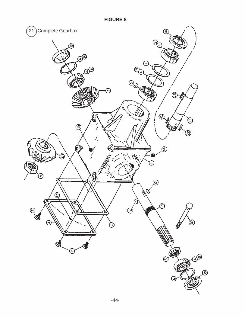
FIGURE 8
-44-
21. Complete Gearbox
-45-
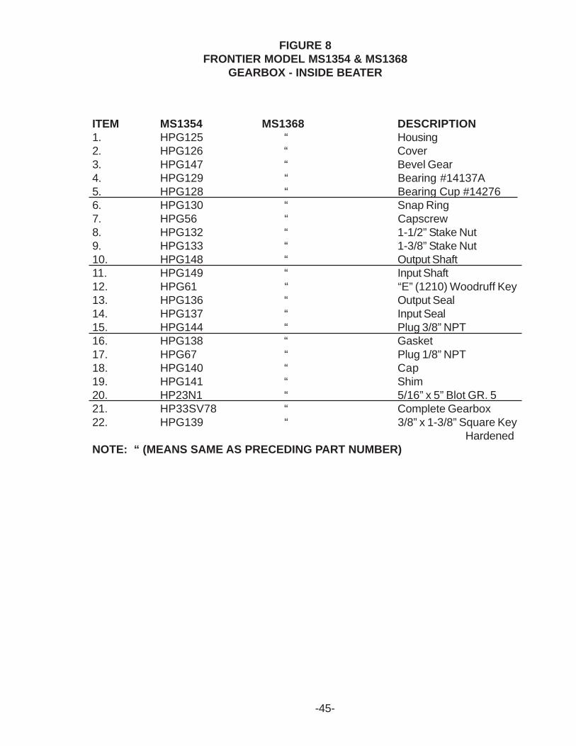
FIGURE 8FRONTIER MODEL MS1354 & MS1368
GEARBOX - INSIDE BEATER
ITEM MS1354 MS1368 DESCRIPTION1. HPG125 “ Housing2. HPG126 “ Cover3. HPG147 “ Bevel Gear4. HPG129 “ Bearing #14137A5. HPG128 “ Bearing Cup #142766. HPG130 “ Snap Ring7. HPG56 “ Capscrew8. HPG132 “ 1-1/2” Stake Nut9. HPG133 “ 1-3/8” Stake Nut10. HPG148 “ Output Shaft11. HPG149 “ Input Shaft12. HPG61 “ “E” (1210) Woodruff Key13. HPG136 “ Output Seal14. HPG137 “ Input Seal15. HPG144 “ Plug 3/8” NPT16. HPG138 “ Gasket17. HPG67 “ Plug 1/8” NPT18. HPG140 “ Cap19. HPG141 “ Shim20. HP23N1 “ 5/16” x 5” Blot GR. 521. HP33SV78 “ Complete Gearbox22. HPG139 “ 3/8” x 1-3/8” Square Key
HardenedNOTE: “ (MEANS SAME AS PRECEDING PART NUMBER)
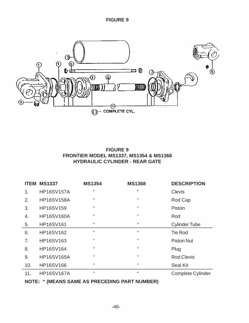
FIGURE 9
-46-
FIGURE 9FRONTIER MODEL MS1337, MS1354 & MS1368
HYDRAULIC CYLINDER - REAR GATE
ITEM MS1337 MS1354 MS1368 DESCRIPTION1. HP16SV157A “ “ Clevis
2. HP16SV158A “ “ Rod Cap3. HP16SV159 “ “ Piston
4. HP16SV160A “ “ Rod
5. HP16SV161 “ “ Cylinder Tube6. HP16SV162 “ “ Tie Rod
7. HP16SV163 “ “ Piston Nut
8. HP16SV164 “ “ Plug9. HP16SV165A “ “ Rod Clevis
10. HP16SV166 “ “ Seal Kit
11. HP16SV167A “ “ Complete CylinderNOTE: “ (MEANS SAME AS PRECEDING PART NUMBER)
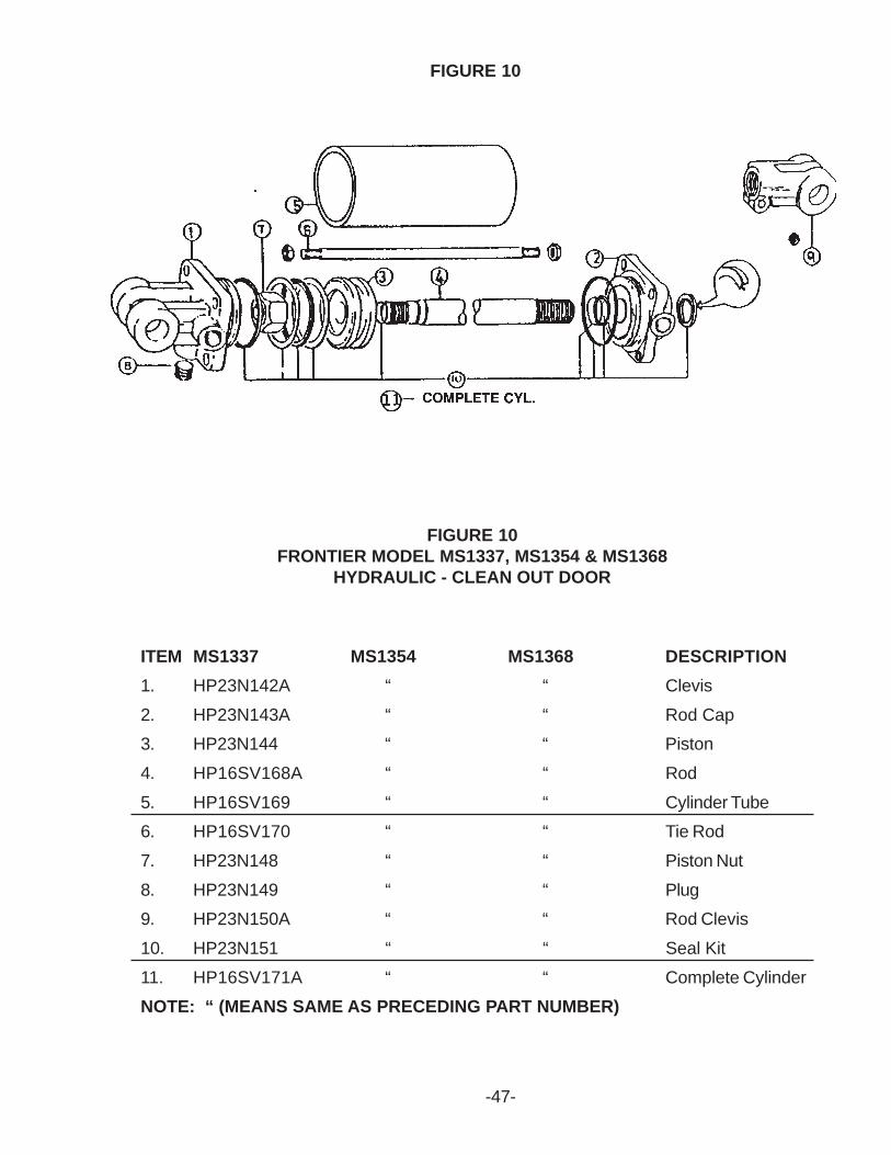
FIGURE 10
-47-
FIGURE 10FRONTIER MODEL MS1337, MS1354 & MS1368
HYDRAULIC - CLEAN OUT DOOR
ITEM MS1337 MS1354 MS1368 DESCRIPTION1. HP23N142A “ “ Clevis
2. HP23N143A “ “ Rod Cap3. HP23N144 “ “ Piston
4. HP16SV168A “ “ Rod
5. HP16SV169 “ “ Cylinder Tube6. HP16SV170 “ “ Tie Rod
7. HP23N148 “ “ Piston Nut
8. HP23N149 “ “ Plug9. HP23N150A “ “ Rod Clevis
10. HP23N151 “ “ Seal Kit
11. HP16SV171A “ “ Complete CylinderNOTE: “ (MEANS SAME AS PRECEDING PART NUMBER)
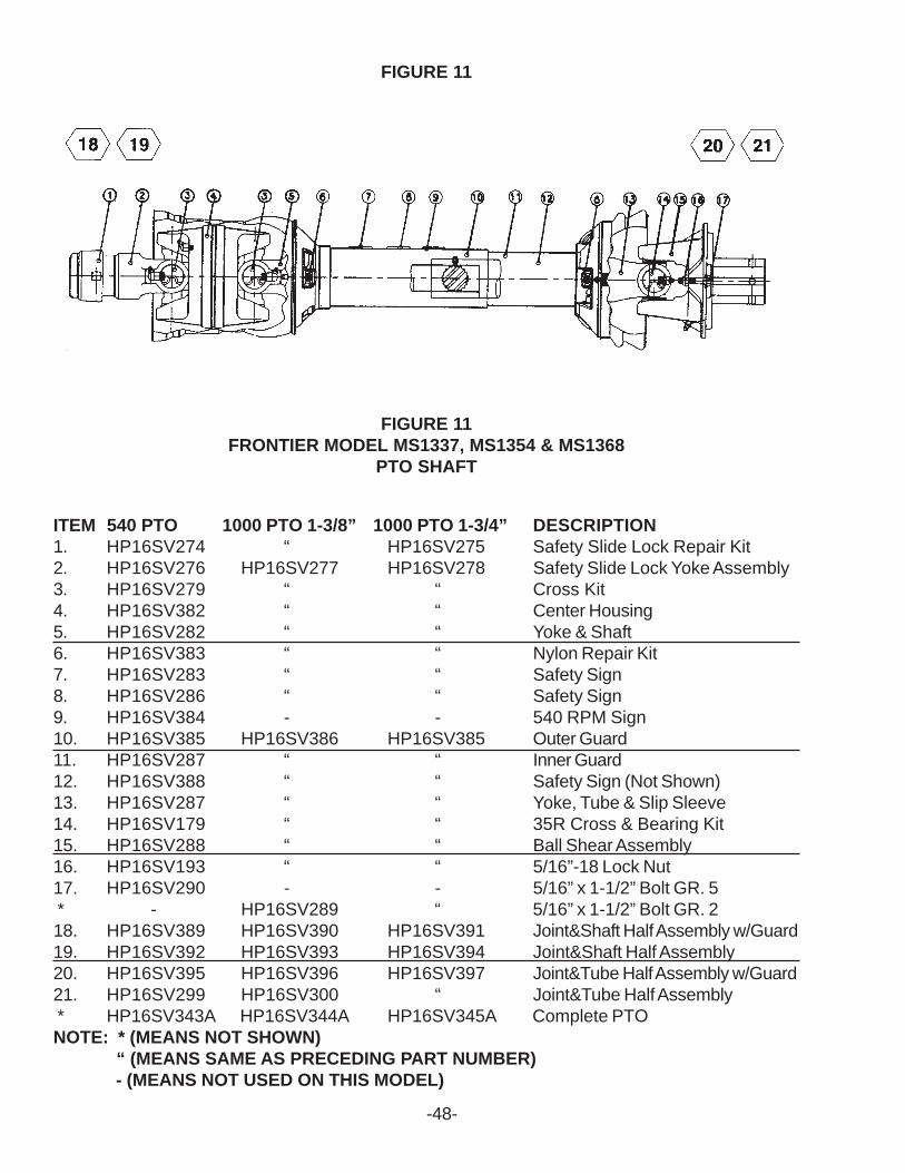
FIGURE 11
-48-
FIGURE 11FRONTIER MODEL MS1337, MS1354 & MS1368
PTO SHAFT
ITEM 540 PTO 1000 PTO 1-3/8” 1000 PTO 1-3/4” DESCRIPTION1. HP16SV274 “ HP16SV275 Safety Slide Lock Repair Kit2. HP16SV276 HP16SV277 HP16SV278 Safety Slide Lock Yoke Assembly3. HP16SV279 “ “ Cross Kit4. HP16SV382 “ “ Center Housing5. HP16SV282 “ “ Yoke & Shaft6. HP16SV383 “ “ Nylon Repair Kit7. HP16SV283 “ “ Safety Sign8. HP16SV286 “ “ Safety Sign9. HP16SV384 - - 540 RPM Sign10. HP16SV385 HP16SV386 HP16SV385 Outer Guard11. HP16SV287 “ “ Inner Guard12. HP16SV388 “ “ Safety Sign (Not Shown)13. HP16SV287 “ “ Yoke, Tube & Slip Sleeve14. HP16SV179 “ “ 35R Cross & Bearing Kit15. HP16SV288 “ “ Ball Shear Assembly16. HP16SV193 “ “ 5/16”-18 Lock Nut17. HP16SV290 - - 5/16” x 1-1/2” Bolt GR. 5 * - HP16SV289 “ 5/16” x 1-1/2” Bolt GR. 218. HP16SV389 HP16SV390 HP16SV391 Joint&Shaft Half Assembly w/Guard19. HP16SV392 HP16SV393 HP16SV394 Joint&Shaft Half Assembly20. HP16SV395 HP16SV396 HP16SV397 Joint&Tube Half Assembly w/Guard21. HP16SV299 HP16SV300 “ Joint&Tube Half Assembly * HP16SV343A HP16SV344A HP16SV345A Complete PTONOTE: * (MEANS NOT SHOWN)
“ (MEANS SAME AS PRECEDING PART NUMBER) - (MEANS NOT USED ON THIS MODEL)
-49-
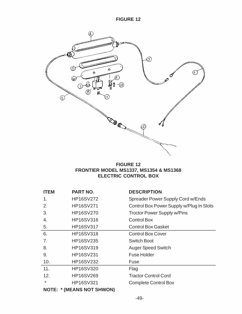
FIGURE 12FRONTIER MODEL MS1337, MS1354 & MS1368
ELECTRIC CONTROL BOX
FIGURE 12
ITEM PART NO. DESCRIPTION1. HP16SV272 Spreader Power Supply Cord w/Ends2. HP16SV271 Control Box Power Supply w/Plug In Slots3. HP16SV270 Troctor Power Supply w/Pins4. HP16SV316 Control Box5. HP16SV317 Control Box Gasket6. HP16SV318 Control Box Cover7. HP16SV235 Switch Boot8. HP16SV319 Auger Speed Switch9. HP16SV231 Fuse Holder10. HP16SV232 Fuse11. HP16SV320 Flag12. HP16SV269 Tractor Control Cord * HP16SV321 Complete Control BoxNOTE: * (MEANS NOT SHWON)
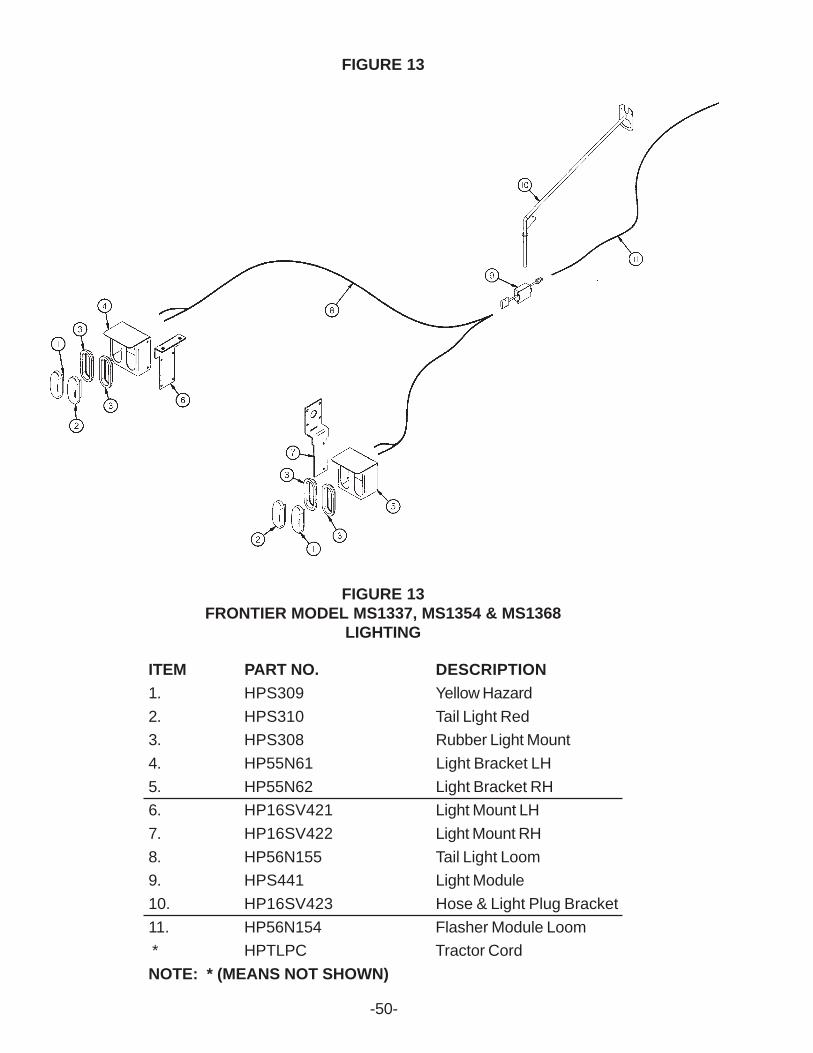
FIGURE 13
FIGURE 13FRONTIER MODEL MS1337, MS1354 & MS1368
LIGHTING
ITEM PART NO. DESCRIPTION1. HPS309 Yellow Hazard2. HPS310 Tail Light Red3. HPS308 Rubber Light Mount4. HP55N61 Light Bracket LH5. HP55N62 Light Bracket RH6. HP16SV421 Light Mount LH7. HP16SV422 Light Mount RH8. HP56N155 Tail Light Loom9. HPS441 Light Module10. HP16SV423 Hose & Light Plug Bracket11. HP56N154 Flasher Module Loom * HPTLPC Tractor CordNOTE: * (MEANS NOT SHOWN)
-50-

SERVICE / MAINTENANCE RECORD
DATE DESCRIPTION NOTES
-51-