S200 Over / Under Pressure Slam Shut Valve Inlet Pressure up to 19 bar L.P. & H.P. Versions Commissioning Instructions General Arrangements Parts Lists Maintenance Instructions For: S200 Slam Shut Valve 50mm, 80mm and 100mm size
Transcript
S200
Over / Under Pressure Slam Shut ValveInlet Pressure up to 19 bar L.P. & H.P. Versions
Commissioning Instructions
General Arrangements
Parts Lists
Maintenance Instructions
For: S200 Slam Shut Valve
50mm, 80mm and 100mm size
2
S200: Commissioning Instructions
FITTING SLAM SHUT INTO PIPEWORK INSTALLATION INSTRUCTIONS (Fig 1)
1. The unit should not be installed in a corrosive environment.
2. The ambient temperature (surface temperature) should be within the limits stated on the slam shut valve catalogue.
3. Check the maximum allowable pressure on the slam shut valve nameplate against the installation specification. Remove protective discs from flanges on inlet and outlet ports.
4. Ensure installation pipework is thoroughly clean.
5. The direction of gas flow must be the same as the arrows on the slam shut body.
6. Install the slam shut valve into the pipework, using gaskets and bolting approved to National Standards.
7. Connect impulse line to sense chamber tapping, using jointing compound approved to National Standards.
8. Vent line can be installed as below if required: Remove vent protective screen and connect vent pipe line to top cover, using jointing compound approved to National Standards.
9. Lead pipe to atmosphere in accordance with National Standards.
10. Ensure no water can penetrate pipe termination point.
VALVE OPERATION (Fig 2).
As the sense pressure rises to the desired trip point, it acts against the pressure sensing diaphragm and pressure setting spring.
A bearing cage is lifted, allowing ball bearings to move radially outwards against the bearing cage taper, to a point where the shoulder diameter on the spring loaded shaft, is free to pass through the bearings (TRIP POINT).
As the shaft moves through the bearings, it releases the spring clip (a) thereby allowing the valve seat assembly to operate in the closed position.
Impulse Sense Connection
Vent Connection
Fig. 1
Fig. 2
a
3
S200: Commissioning Instructions
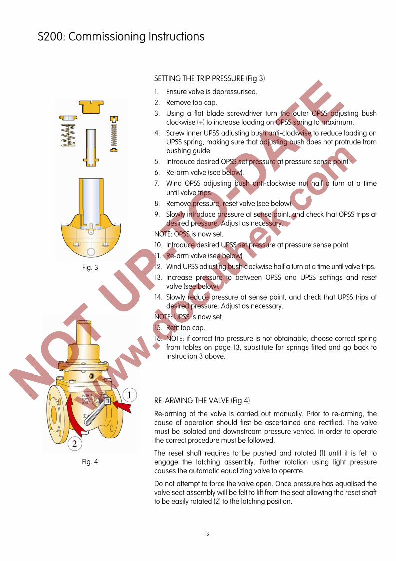
SETTING THE TRIP PRESSURE (Fig 3)
1. Ensure valve is depressurised. 2. Remove top cap. 3. Using a flat blade screwdriver turn the outer OPSS adjusting bush
clockwise (+) to increase loading on OPSS spring to maximum. 4. Screw inner UPSS adjusting bush anti-clockwise to reduce loading on
UPSS spring, making sure that adjusting bush does not protrude from bushing guide.
5. Introduce desired OPSS set pressure at pressure sense point. 6. Re-arm valve (see below). 7. Wind OPSS adjusting bush anti-clockwise nut half a turn at a time
until valve trips. 8. Remove pressure, reset valve (see below). 9. Slowly introduce pressure at sense point, and check that OPSS trips at
desired pressure. Adjust as necessary. NOTE: OPSS is now set. 10. Introduce desired UPSS set pressure at pressure sense point. 11. Re-arm valve (see below). 12. Wind UPSS adjusting bush clockwise half a turn at a time until valve trips.13. Increase pressure to between OPSS and UPSS settings and reset
valve (see below). 14. Slowly reduce pressure at sense point, and check that UPSS trips at
desired pressure. Adjust as necessary. NOTE: UPSS is now set. 15. Refit top cap. 16. NOTE; if correct trip pressure is not obtainable, choose correct spring
from tables on page 13, substitute for springs fitted and go back to instruction 3 above.
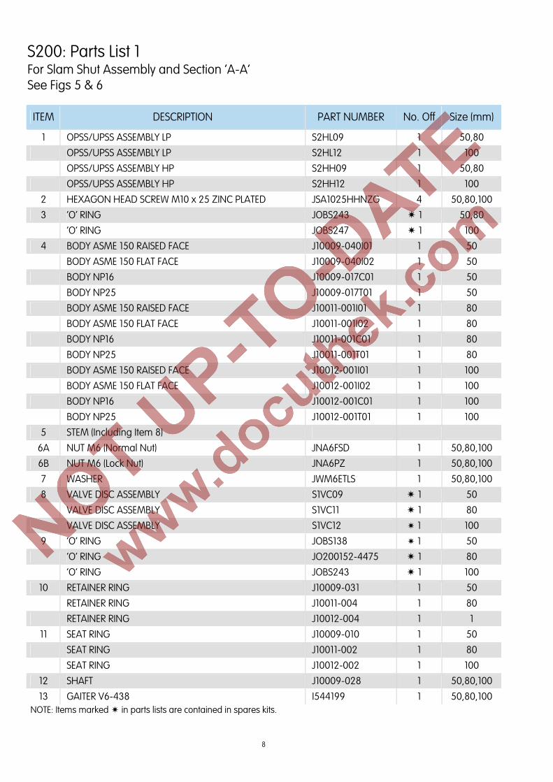
RE-ARMING THE VALVE (Fig 4)
Re-arming of the valve is carried out manually. Prior to re-arming, the cause of operation should first be ascertained and rectified. The valve must be isolated and downstream pressure vented. In order to operate the correct procedure must be followed.
The reset shaft requires to be pushed and rotated (1) until it is felt to engage the latching assembly. Further rotation using light pressure causes the automatic equalizing valve to operate.
Do not attempt to force the valve open. Once pressure has equalised the valve seat assembly will be felt to lift from the seat allowing the reset shaft to be easily rotated (2) to the latching position.
Fig. 3
Fig. 4
4
S200: General Arrangement
SLAM SHUT ASSEMBLY Fig. 5
1
7
6A
5
4
3
2
8
9
11
10
6B 201916 15 1812 13 14 15 16 17
ALTERNATIVE VERSION (Washer Item 7 Not Required)
SECTION A-A Fig. 6
A
A
5
S200: General Arrangement
LOW PRESSURE OPSS/UPSS ASSEMBLY Fig. 7
16 17 18 19 20 21 22
38
37
36
35
34
33
32
31
29
28
27
26
25
24
23
1
2
3
4
5
6
7
8
9
10
11
12
13
14
15
6
S200: General Arrangement
HIGH PRESSURE OPSS/UPSS ASSEMBLY Fig 8
18 19 20 21 22 23 2417 16 26 25 27
43
42
41
40
39
37
36
35
34
33
32
31
30
29
28
38
1
2
3
4
5
6
7
8
9
10
11
12
13
14
15
7
VISUAL INDICATOR WITH MICRO SWITCH
Fig. 9
VISUAL INDICATOR Fig. 10
15
16
1
9
8
12 1
2
3
4
5
6
7
1119 18 17 16 15 14 13
1
10
9
8
32 18 17 1
20
19
21
6
7
S200: General Arrangement
8
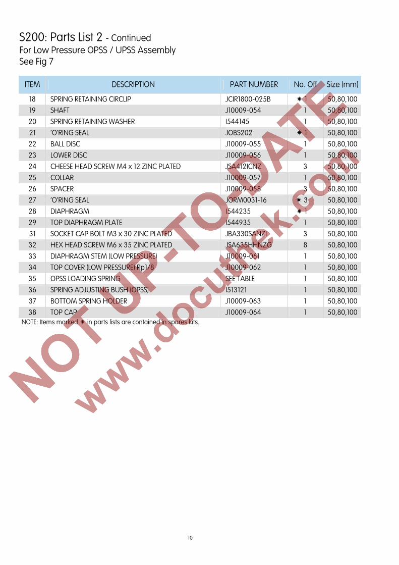
ITEM DESCRIPTION PART NUMBER No. Off Size (mm)
1 OPSS/UPSS ASSEMBLY LP S2HL09 1 50,80
OPSS/UPSS ASSEMBLY LP S2HL12 1 100
OPSS/UPSS ASSEMBLY HP S2HH09 1 50,80
OPSS/UPSS ASSEMBLY HP S2HH12 1 100
2 HEXAGON HEAD SCREW M10 x 25 ZINC PLATED JSA1025HHNZG 4 50,80,100
3 ‘O’ RING JOBS243 1 50,80
‘O’ RING JOBS247 1 100
4 BODY ASME 150 RAISED FACE J10009-040I01 1 50
BODY ASME 150 FLAT FACE J10009-040I02 1 50
BODY NP16 J10009-017C01 1 50
BODY NP25 J10009-017T01 1 50
BODY ASME 150 RAISED FACE J10011-001I01 1 80
BODY ASME 150 FLAT FACE J10011-001I02 1 80
BODY NP16 J10011-001C01 1 80
BODY NP25 J10011-001T01 1 80
BODY ASME 150 RAISED FACE J10012-001I01 1 100
BODY ASME 150 FLAT FACE J10012-001I02 1 100
BODY NP16 J10012-001C01 1 100
BODY NP25 J10012-001T01 1 100
5 STEM (Including Item 8)
6A NUT M6 (Normal Nut) JNA6FSD 1 50,80,100
6B NUT M6 (Lock Nut) JNA6PZ 1 50,80,100
7 WASHER JWM6ETLS 1 50,80,100
8 VALVE DISC ASSEMBLY S1VC09 1 50
VALVE DISC ASSEMBLY S1VC11 1 80
VALVE DISC ASSEMBLY S1VC12 1 100
9 ‘O’ RING JOBS138 1 50
‘O’ RING JO200152-4475 1 80
‘O’ RING JOBS243 1 100
10 RETAINER RING J10009-031 1 50
RETAINER RING J10011-004 1 80
RETAINER RING J10012-004 1 1
11 SEAT RING J10009-010 1 50
SEAT RING J10011-002 1 80
SEAT RING J10012-002 1 100
12 SHAFT J10009-028 1 50,80,100
13 GAITER V6-438 I544199 1 50,80,100 NOTE: Items marked in parts lists are contained in spares kits.
S200: Parts List 1 For Slam Shut Assembly and Section ‘A-A’ See Figs 5 & 6
9
ITEM DESCRIPTION PART NUMBER No. Off Size (mm)
14 RESET SHAFT BUSH J10009-029 1 50,80,100
15 ‘O’ RING JOBS012 2 50,80,100
16 ‘O’ RING JOBS015 2 50,80,100
17 CLOSING SPRING J10009-030 1 50
CLOSING SPRING J10011-005 1 80
CLOSING SPRING J10012-005 1 100
18 LEVER ASSEMBLY S1LC09 1 50
LEVER ASSEMBLY S1LC11 1 80
LEVER ASSEMBLY S1LC12 1 100
19 SPRING J10009-005 1 50,80,100
20 SPRING RESET SHAFT BUSH J10009-023 1 50,80,100 NOTE: Items marked in parts lists are contained in spares kits.
S200: Parts List 1 - Continued For Slam Shut Assembly and Section ‘A-A’ See Figs 5 & 6
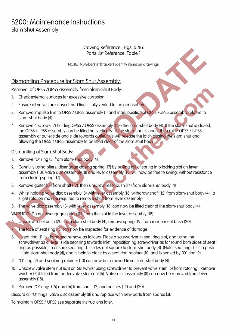
ITEM DESCRIPTION PART NUMBER No. Off Size (mm)
1 ‘O’RING SEAL (TOP CAP) JOBS120 1 50,80,100
2 SPRING ADJUSTING BUSH (UPSS) J10009-047 1 50,80,100
3 SPRING HOUSING BUSH J10009-048 1 50,80,100
4 UPSS LOADING SPRING SEE TABLE 1 50,80,100
5 UPSS BOTTOM GUIDE J10009-049 1 50,80,100
6 ‘O’RING SEAL JOBS009 1 50,80,100
7 CHEESE HEAD SCREW M4 x 10 ZINC PLATED JSA410ICNZ 1 50,80,100
19 LOCATING BUSH (SHAFT ASSEMBLY) I544270D 1 50,80,100
20 OBSCURING RING (NO MICRO SWITCH) I544263A 1 50,80,100
21 SPY GLASS (NO MICRO SWITCH) I544263B 1 50,80,100 NOTE: Items marked in parts lists are contained in spares kits.
13
S200: Spring Tables
OPSS SPRINGS All Sizes LOW PRESSURE
mbar ”wg PART No. COLOUR CODE
24 – 40 10 - 16 J10009-011 -
35 – 70 14 – 28 J10009-012 LIGHT BLUE
70 - 140 28 – 56 J10009-013 RED / BROWN
140 - 210 56 – 84 J10009-014 PURPLE
210 - 350 84 – 140 J10009-015 ORANGE – YELLOW
350 - 700 140 – 280 J10009-016 ORANGE – DARK GREEN
UPSS SPRINGS All Sizes
mbar ”wg PART No. COLOUR CODE
5 - 15 2 – 6 J10009-042 WHITE / BLACK
10 - 50 4 – 20 J10009-043 WHITE / ORANGE
40 - 120 16 – 48 J10009-044 WHITE / RED
90 - 250 36 – 100 J10009-045 WHITE / LIGHT BLUE
OPSS SPRINGS All Sizes HIGH PRESSURE
bar PSIG PART No. COLOUR CODE
0.7 – 1.4 10.1 – 20.3 J10009-013 RED / BROWN
1.4 – 2.1 20.3 – 30.5 J10009-014 PURPLE
2.1 – 3.5 30.5 – 50.7 J10009-015 ORANGE – YELLOW
3.5 – 7.0 50.7 – 101.5 J10009-016 ORANGE – DARK GREEN
4.0 – 8.0 58.0 – 116.0 J10009-046 ORANGE - PURPLE
UPSS SPRINGS All Sizes
mbar ”wg PART No. COLOUR CODE
50 - 150 20 – 60 J10009-042 WHITE / BLACK
100 - 500 40 – 201 J10009-043 WHITE / ORANGE
400 - 1200 160 – 482 J10009-044 WHITE / RED
900 - 2500 361 – 1004 J10009-045 WHITE / LIGHT BLUE
SPARES KITS
Size Low Pressure High Pressure
50mm SK209-01 SK209-02
80mm SK211-01 SK211-02
100mm SK212-01 SK212-02
14
S200: Maintenance Instructions Slam Shut Assembly
Drawing Reference: Figs. 5 & 6 Parts List Reference: Table 1
NOTE: Numbers in brackets identify items on drawings
Dismantling Procedure for Slam Shut Assembly: Removal of OPSS /UPSS assembly from Slam-Shut Body:
1. Check external surfaces for excessive corrosion.
2. Ensure all valves are closed, and line is fully vented to the atmosphere.
3. Remove impulse line to OPSS / UPSS assembly (1) and mark position of OPSS /UPSS assembly relative to slam-shut body (4).
4. Remove 4 screws (2) holding OPSS / UPSS assembly (1) to the slam-shut body (4). If the slam-shut is closed, the OPSS /UPSS assembly can be lifted out vertically. If the slam-shut is open, then raise OPSS / UPSS assembly at outlet side and slide towards outlet, this will release the latch closing the slam shut and allowing the OPSS / UPSS assembly to be lifted clear of the slam shut body.
Dismantling of Slam-Shut Body:
1. Remove "O" ring (3) from slam-shut body (4).
2. Carefully using pliers, disengage closing spring (17) by pulling tail of spring into locking slot on lever assembly (18). Valve disc assembly (8) and lever assembly (18) will now be free to swing, without resistance from closing spring (17).
3. Remove gaiter (13) from shaft (12), then unscrew reset bush (14) from slam-shut body (4)
4. Whilst holding valve disc assembly (8) with lever assembly (18) withdraw shaft (12) from slam-shut body (4). (a slight rotation may be required to remove shaft from lever assembly).
5. The valve disc assembly (8) with lever assembly (18) can now be lifted clear of the slam-shut body (4).
WARNING: Do not disengage spring (17) from the slot in the lever assembly (18).
6. Unscrew reset bush (20) from slam shut body (4), remove spring (19) from inside reset bush (20).
7. The face of seat ring (11) can now be inspected for evidence of damage.
8. If seat ring (11) is damaged remove as follows: Place a screwdriver in seat ring slot, and using the screwdriver as a lever, slide seat ring towards inlet, repositioning screwdriver as far round both sides of seat ring as possible, to ensure seat ring (11) slides out square to slam-shut body (4). (Note: seat ring (11) is a push fit into slam-shut body (4), and is held in place by a seat ring retainer (10) and is sealed by "O" ring (9).
9. "O" ring (9) and seat ring retainer (10) can now be removed from slam-shut body (4).
10. Unscrew valve stem nut (6A) or (6B) (whilst using screwdriver to prevent valve stem (5) from rotating), Remove washer (7) if fitted from under valve stem nut (6). Valve disc assembly (8) can now be removed from lever assembly (18).
11. Remove "O" rings (15) and (16) from shaft (12) and bushes (14) and (20).
Discard all "O" rings, valve disc assembly (8) and replace with new parts from spares kit.
To maintain OPSS / UPSS see separate instructions later.
15
S200: Maintenance Instructions Slam Shut Assembly
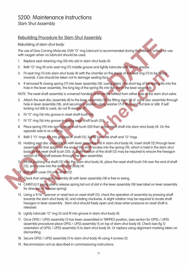
Rebuilding Procedure for Slam-Shut Assembly.
Rebuilding of slam-shut body:
The use of Dow Corning Molycote 55M "O" ring lubricant is recommended during the rebuild- unless for use with oxygen when no lubricant should be used.
1. Replace seat retaining ring (10) into slot in slam-shut body (4).
2. Refit "O" ring (9) onto seat ring (11) middle groove and lightly lubricate with silicon grease.
3. Fit seat ring (11) into slam-shut body (4) with the chamfer on the inside of the seat ring (11) to be facing inwards. Care should be taken not to damage seating face.
4. If removed fit closing spring (17) into lever assembly (18), (using pliers ) the short leg of the spring fits into the hole in the lever assembly, the long leg of the spring fits into the slot in the lever assembly.
NOTE: The reset shaft assembly is universal handed, and can be refitted from either side of the slam shut valve.
5. Attach the seat disc assembly (8) to the lever assembly (18) by fitting stem (5) of valve disc assembly through hole in lever assembly (18), and securing in position using washer (7) if fitted and nut (6A) or (6B). If self locking nut (6B) is used, do not fit washer (7).
6. Fit "O" ring (16) into groove in reset shaft bush (14).
7. Fit "O" ring (16) into groove in spring reset shaft bush (20).
8. Place spring (19) into spring reset shaft bush (20) then screw reset shaft into slam-shut body (4). On the opposite side to re-cocking.
9. Refit 2 "O" rings (15) into grooves in shaft (12), lightly lubricate shaft and "O" rings.
10. Holding seat disc assembly (8) with lever assembly (18) in slam-shut body (4), insert shaft (12) through lever assembly, so that spigot on the end of the shaft locates into the spring (19), which is held in the slam-shut body by the reset shaft bush (20). (A slight rotation of the shaft (12) may be required to ensure the hexagon section of the shaft passes through the lever assembly).
11. Whilst pushing the shaft (12) in to the slam-shut body (4), place the reset shaft bush (14) over the end of shaft (12), and screw into the slam-shut body (4).
12. Refit shaft cover (13) onto shaft (12).
13. Check that valve disc assembly (8) with lever assembly (18) is free to swing.
14. CAREFULLY (using pliers) release spring tail out of slot in the lever assembly (18) (see label on lever assembly for direction to release spring).
15. Using a 9/16" Spanner or reset tool on reset shaft (12), check the operation of assembly by pressing shaft towards the slam-shut body (4), and rotating clockwise. A slight rotation may be required to locate shaft hexagon in lever assembly. Slam-shut should freely open and close when pressure on reset shaft is released.
16. Lightly lubricate "O" ring (3) and fit into groove in slam-shut body (4).
17. Once OPSS / UPSS assembly (1) has been assembled in TRIPPED position, (see section for OPSS / UPSS assembly procedure) place OPSS / UPSS assembly (1) on top of slam-shut body (4). Check (see fig 5) orientation of OPSS / UPSS assembly (1) to slam-shut body (4). Or replace using alignment marking taken on dismantling.
18. Secure OPSS / UPSS assembly (1) to slam-shut body (4) using 4 screws (2).
19. Recommission unit as described in commissioning instructions.
Drawing Reference: Figs. 7 Parts List Reference: Table 2
NOTE: Numbers in brackets identify items on drawings
Dismantling Procedure for Low Pressure OPSS / UPSS Assembly: If micro switch or visual indicator are fitted refer to page 24. 1. Unscrew top cap (38) together with "O" ring (1) from spring housing bush (3).
2. Remove "O" ring (1) from top cap (38).
3. Unscrew and remove OPSS adjusting bush (36), take out OPSS loading spring (35) and bottom spring holder (37).
4. Take UPSS adjusting bush (2) from bottom spring holder (37) and withdraw UPSS loading spring (4) and UPSS bottom guide (5).
5. Make note of the position of the vent in the top cover (34), relative to the horizontal tapped hole in the adaptor body (9).
6. Remove 8 screws (32) holding top cover (34) onto the adaptor body (9), then lift off top cover (34).
7. Unscrew 3 cap head bolts (31) and lift off diaphragm assembly from adaptor body (9), taking care that all 6 balls (15) fall into adaptor body (9).
8. Remove all 6 balls (15) from adaptor body (9).
9. Take 3 spacers (26) and “O” rings (27) from diaphragm assembly.
10. Unscrew Cheese head screw (7) and separate diaphragm assembly components – top diaphragm plate (29), diaphragm (28), bottom diaphragm plate (8) and L.P. diaphragm stem (33), removing “O” ring (6).
11. Undo and remove 3 cheese head screws (12) and lift off upper disc (13) and 3 upper disc spacers (14).
12. Take off ball disc (22).
13. Place adaptor body (9) in vice fitted with soft jaws, with shut off spring (17) facing downward. Take care not to over tighten which could result in damage it the body.
14. Compress shut off spring (17) by pushing shaft (19) upwards. Using fine pointed pliers remove upper circlip (10), take off collar (25) and remove lower circlip (10). As circlips are small care must be taken so that they are not misplaced.
15. Shut off spring (17), retainer (20) and shaft (19) can now be withdrawn from adaptor body (9).
16. Remove adaptor body (9) from vice, remove “O” ring (16).
17. Remove 3 cheese head screws (24) and take off lower disc (23).
18. Take out “O” ring (21) from adaptor body (9).
19. It is not necessary to remove retainer (20) and circlip (18) from shaft (19) unless damaged.
Discard "O" rings and diaphragm (28) and replace with new parts from spares kit.
Rebuilding Procedure for Low Pressure OPSS / UPSS Assembly.
The use of Dow Corning Molycote 55M "O" ring lubricant is recommended during the rebuild- unless for use with oxygen when no lubricant should be used.
1. Fit "O" ring (21) into adaptor body (9), taking care not to damage it whilst fitting (use only blunt nose tools if needed).
2. Secure lower disc (23) using 3 cheese head screws (24) onto adaptor body (9).
3. Fit shock absorber "O" ring (16) into recess in lower disc (23).
4. Place adaptor body assembly (9) in vice, fitted with soft jaws, with underside facing upwards. Take care not to over tighten which could result in damage to the body.
5. If previously removed, refit circlip (18), retainer (20) and shut off spring (17) over rounded end of shaft (19).
6. Lightly lubricate shaft (19) with silicon grease, push square end through adaptor body (9) and lower disc (23).
7. To enable shut off spring (17) to be compressed for refitting of circlip (10), it may be necessary to place packing below the shaft (19) in the vice. Using suitable tool, add circlip (10) into the groove on shaft (19) nearest to adaptor body (9), so spring (17) and spring retaining washer (20) are held in position.
8. Remove adaptor body assembly (9) from vice, then invert and reclamp in vice. Place collar (25) over shaft (19) with counter bore of collar facing adaptor body (9), retain collar (25) in position on shaft (19), by fitting circlip (10) using tool, into remaining groove on shaft (19).
9. Place “O” ring (6) into recess in L.P. diaphragm stem (33).
10. Pass screw (7) through bottom diaphragm plate (8), diaphragm (28) and top diaphragm plate (29) ensuring that lips of plates face away from diaphragm and that radial holes in plates and diaphragm line up.
11. Fasten screw (7) into L.P. diaphragm stem (33) and tighten.
12. Insert 3 cap head bolts (31) through holes in upper diaphragm plate (29).
13. Add 3 “O” rings (27) and 3 spacers (26) with hexagonal end towards diaphragm, over screws (31) and restrain with a small amount of silicon grease.
14. Lift shaft (19) as high as possible by compressing shut off spring (17) and hold in position.
15. Apply grease to 6 balls (15), locate balls around shaft (19) on top face of lower disc (23), grease will hold the balls in position.
16. Place ball disc (22) with lip facing downward, over ring of balls and restrain with silicon grease. Threaded holes should be roughly aligned with screw heads in lower disc (23).
17. Stand 3 upper disc spacers (14) over threaded holes in lower disc (23).
18. Position upper disc (13) onto upper disc spacers (14) with lip facing downward and secure using 3 cheese head screws (12) taking care not to disturb balls (15) or ball disc (22).
19. Carefully introduce diaphragm assembly (28) by lowering spacers (26) through holes in upper disc (13) until 3 cap head bolts (31) can be fastened to ball disc (22). Ensure that holes around edge of diaphragm (28) line up with holes in adaptor body (9).
20. Release compression on shut off spring (17).
21. Place L.P. top cover (34) onto adaptor body assembly (9). Ensure holes in diaphragm (28), adaptor body (9) and L.P. top cover (34) line up. Clamp L.P. top cover (34) onto adaptor body assembly (9), using 8 hexagon head screws (32) and 8 nuts (11).
NOTE: The position of the vent in the L.P. top cover (34), relative to the tapped hole in the side of the adaptor body (9) should be as noted during dismantling.
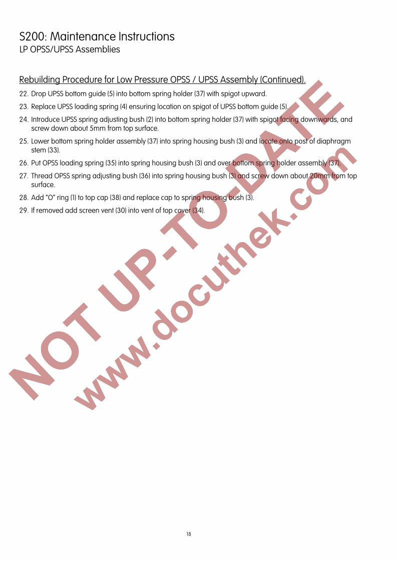
Rebuilding Procedure for Low Pressure OPSS / UPSS Assembly (Continued). 22. Drop UPSS bottom guide (5) into bottom spring holder (37) with spigot upward.
23. Replace UPSS loading spring (4) ensuring location on spigot of UPSS bottom guide (5).
24. Introduce UPSS spring adjusting bush (2) into bottom spring holder (37) with spigot facing downwards, and screw down about 5mm from top surface.
25. Lower bottom spring holder assembly (37) into spring housing bush (3) and locate onto post of diaphragm stem (33).
26. Put OPSS loading spring (35) into spring housing bush (3) and over bottom spring holder assembly (37).
27. Thread OPSS spring adjusting bush (36) into spring housing bush (3) and screw down about 20mm from top surface.
28. Add “O” ring (1) to top cap (38) and replace cap to spring housing bush (3).
29. If removed add screen vent (30) into vent of top cover (34).
19
S200: Maintenance Instructions HP OPSS/UPSS Assemblies
Drawing Reference: Figs. 8 Parts List Reference: Table 3
NOTE: Numbers in brackets identify items on drawings
Dismantling Procedure for High Pressure OPSS / UPSS Assembly: If micro switch or visual indicator are fitted refer to page 24. 1. Unscrew top cap (43) together with gasket (1) from spring housing bush (3).
2. Remove gasket (1) from top cap (43).
3. Unscrew and remove OPSS adjusting bush (41), take out OPSS loading spring (40) and bottom spring holder (42).
4. Take UPSS adjusting bush (2) from bottom spring holder (42) and withdraw UPSS loading spring (4) and UPSS bottom guide (5).
5. Make note of the position of the vent in the top cover (39), relative to the horizontal tapped hole in the adaptor body (10).
6. Remove 8 hex head screws (9) and nuts (11) holding top cover (39) onto the adaptor body (10).
7. Withdraw retaining pin (34) and lift off top cover (39).
8. Unscrew 3 cap head bolts (31) and lift off diaphragm assembly from adaptor body (10), taking care that all 6 balls (18) fall into adaptor body (10).
9. Remove all 6 balls (18) from adaptor body (10).
10. Take 3 spacers (28) and “O” rings (29) from diaphragm plate (30).
11. Unscrew 4 cheese head screws (35) and remove collar (8) and diaphragm assembly (7).
12. Separate diaphragm assembly components – upper diaphragm cup (38), diaphragm (7), lower diaphragm cup (36) and H.P. diaphragm stem (6).
13. Undo and remove 3 cheese head screws (14) and lift off upper disc (27) and 3 upper disc spacers (15).
14. Take off ball disc (17).
15. Place adaptor body (10) in vice fitted with soft jaws, with shut off spring (20) facing downward. Take care not to over tighten which could result in damage it the body.
16. Compress shut off spring (20) by pushing shaft (22) upwards. Using fine pointed pliers remove upper circlip (13), take off collar (25) and remove lower circlip (13). As circlips are small care must be taken so that they are not misplaced.
17. Shut off spring (20), retainer (23) and shaft (22) can now be withdrawn from adaptor body (10).
18. Remove adaptor body (10) from vice, remove “O” ring (19).
19. Remove 3 cheese head screws (26) and take off lower disc (16).
20. Take out “O” ring (24) from adaptor body (10).
21. It is not necessary to remove retainer (23) and circlip (21) from shaft (22) unless damaged.
Discard "O" rings and diaphragm (7) and replace with new parts from spares kit.
20
S200: Maintenance Instructions HP OPSS/UPSS Assemblies
Rebuilding Procedure for High Pressure OPSS / UPSS Assembly.
The use of Dow Corning Molycote 55M "O" ring lubricant is recommended during the rebuild- unless for use with oxygen when no lubricant should be used.
1. Fit "O" ring (24) into adaptor body (10), taking care not to damage it whilst fitting (use only blunt nose tools if needed).
2. Secure lower disc (16) using 3 cheese head screws (26) onto adaptor body (10). 3. Fit shock absorber "O" ring (19) into recess in lower disc (16). 4. Place adaptor body assembly (10) in vice, fitted with soft jaws, with underside facing upwards. Take care not
to over tighten which could result in damage to the body. 5. If previously removed, refit circlip (21), retainer (23) and spring (20) over rounded end of shaft (22). 6. Lightly cover shaft (22) with silicon grease, push square end through adaptor body (10) and lower disc (16). 7. To enable shut off spring (20) to be compressed for refitting of circlip (13), it may be necessary to place
packing below the shaft (22) in the vice. Using suitable tool, add circlip (13) into the groove on shaft (22) nearest to adaptor body (10), so spring (22) and spring retaining washer (23) are held in position.
8. Remove adaptor body assembly (10) from vice, then invert and reclamp in vice. Place collar (25) over shaft (22) with counter bore of collar facing adaptor body (10), retain collar (25) in position on shaft (22), by fitting circlip (13) using tool, into remaining groove on shaft (22).
9. Pass screw (12) through bottom diaphragm plate (30), from concave side, and into stem nut (33) and tighten.10. Insert 3 cap head bolts (31) through holes in diaphragm plate (29). 11. Add 3 “O” rings (29) and 3 spacers (28) with hexagonal end towards diaphragm plate, over screws (31) and
restrain with a small amount of silicon grease. 12. Lift shaft (22) as high as possible by compressing shut off spring (20) and hold in position. 13. Apply grease to 6 balls (18), locate balls around shaft (22) on top face of lower disc (16), grease will hold the
balls in position. 14. Place ball disc (17) with lip facing downward, over ring of balls and restrain with silicon grease. Threaded
holes should be roughly aligned with screw heads in lower disc (16). 15. Stand 3 upper disc spacers (15) over threaded holes in lower disc (16). 16. Position upper disc (27) onto upper disc spacers (15) with lip facing downward and secure using 3 cheese
head screws (14) taking care not to disturb balls (18) or ball disc (27). 17. Carefully introduce diaphragm plate assembly (30) by lowering spacers (28) through holes in upper disc (27)
until 3 screws (31) can be fastened to ball disc (27). 18. Release compression on shut off spring (20). 19. Pass H.P. diaphragm (6) stem through lower diaphragm cup (36), H.P. diaphragm (7), keeping diaphragm
bead facing away from screw head, and screw into rounded end of upper diaphragm cup (38). 20. Invert H.P. top cover (39) and position diaphragm assembly (7) with diaphragm bead in groove in H.P. top
cover (39). 21. Secure with collar (8), ensuring that rounded side of inner hole is against diaphragm (7), and 4 cheese head
screws (35). 22. Hold H.P. top cover assembly (39) over adaptor body (10) and extend diaphragm plate assembly (29)
upwards and diaphragm assembly (7) downwards, until they can be joined using retaining pin (34). 23. Lower H.P. top cover (39) onto adaptor body assembly (10). Ensure holes in adaptor body (10) and top cover
(39) line up. Clamp H.P. top cover (39) onto adaptor body assembly (10), using 8 hexagon head screws (9) and 8 nuts (11).
NOTE: The position of the vent in the H.P. top cover (39), relative to the tapped hole in the side of the adaptor body (9) should be as noted during dismantling.
21
S200: Maintenance Instructions HP OPSS/UPSS Assemblies
Rebuilding Procedure for High Pressure OPSS / UPSS Assembly (Continued): 24. Drop UPSS bottom guide (5) into bottom spring holder (42) with spigot upward. 25. Replace UPSS loading spring (4) ensuring location on spigot of UPSS bottom guide (5). 26. Introduce UPSS spring adjusting bush (2) into bottom spring holder (42) with spigot facing downwards, and
screw down about 5mm from top surface. 27. Lower bottom spring holder assembly (42) into spring housing bush (3) and locate onto post of H.P.
diaphragm stem (6). 28. Put OPSS loading spring (40) into spring housing bush (3) and over bottom spring holder assembly (42). 29. Thread OPSS spring adjusting bush (41) into spring housing bush (3) and screw down about 20mm from top
surface. 30. Add gasket (1) to top cap (43) and replace cap to spring housing bush (3). 31. If removed add screen vent (37) into vent of H.P. top cover (39).
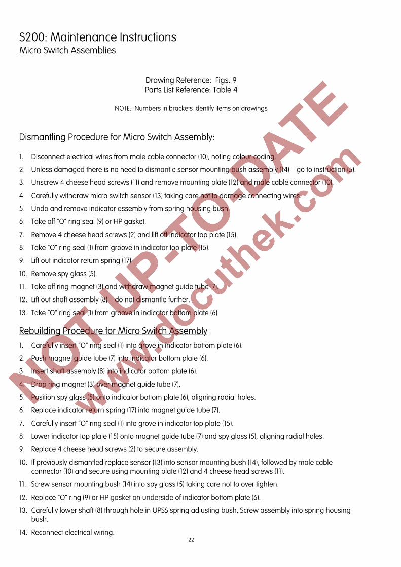
6. Replace indicator return spring (17) into magnet guide tube (7).
7. Carefully insert “O” ring seal (1) into grove in indicator top plate (15).
8. Lower indicator top plate (15) onto magnet guide tube (7) and spy glass (5), aligning radial holes.
9. Replace 4 cheese head screws (2) to secure assembly.
10. If previously dismantled replace sensor (13) into sensor mounting bush (14), followed by male cable connector (10) and secure using mounting plate (12) and 4 cheese head screws (11).
11. Screw sensor mounting bush (14) into spy glass (5) taking care not to over tighten.
12. Replace “O” ring (9) or HP gasket on underside of indicator bottom plate (6).
13. Carefully lower shaft (8) through hole in UPSS spring adjusting bush. Screw assembly into spring housing bush.
6. Replace indicator return spring (17) into magnet guide tube (7).
7. Carefully insert “O” ring seal (1) into grove in indicator top plate (15).
8. Lower indicator top plate (15) onto magnet guide tube (7) and spy glass (21), aligning radial holes.
9. Replace 4 cheese head screws (2) to secure assembly.
10. Replace “O” ring (9) or HP gasket on underside of indicator bottom plate (6).
11. Carefully lower shaft (8) through hole in UPSS spring adjusting bush. Screw assembly into spring housing bush.
Contacts United Kingdom Germany USA Elster Jeavons Elster GmbH Elster American Meter Paton Drive, Tollgate Business Park, Steinern Str. 19 - 21 2221 Industrial Road Beaconside, Stafford, Staffs. ST16 3EF 55252 Mainz-Kastel Nebraska City, NE 68410-6889 T +44 1785 275200 T +49 6134 605 0 T +1 402 873 8200 F +44 1785 275305 F +49 6134 605 223 F +1 402 873 7616 www.elster-instromet.com www.elster-instromet.com www.elster-meterservices.com [email protected][email protected]
MS2002EN03 A22.12.2009
Subj
ect t
o ch
ange
with
out p
rior n
otic
e
All
right
s re
serv
ed
Subj
ect t
o ch
ange
with
out p
rior n
otic
e
All
right
s re
serv
ed
Elster Jeavons is committed to a programme of continuous quality enhancement. All equipment designed by Elster Jeavons and manufactured within the Elster-Instromet Group benefits from the groups quality assurance standards, which are approved to EN ISO9001:2008.
Elster Jeavons has a programme of continuous product development and improvement and in consequence the information in this leaflet may be subject to change or modification without notice.


![[Roche] Scanner Ms200 Brochure 2009-12-22](https://static.documents.pub/doc/80x56/54362ea1219acdd95f8b510d/roche-scanner-ms200-brochure-2009-12-22.jpg)


![produits (13 mars) pp1-9 EN03 OK.qxp:Mise en page 1 · 2018-01-04 · 5 February – March 2009 76th Fête du Citron ® [Lemon Festival] - “Menton celebrates the Music of the World”](https://static.documents.pub/doc/80x56/5f3edc013ea62d67f5009c56/produits-13-mars-pp1-9-en03-okqxpmise-en-page-1-2018-01-04-5-february-a.jpg)


