MSP3000 – MS430501M and MS430503M
Overview
The MS430501M and MS430503M are 2HU chassis which are part of MSP3000
Platform
Product features:
2 RU chassis
Up to 400 Gb/s aggregation and transport
SNMP Management
Command Line interface SSH and Telnet
Three 100M Ethernet management ports
NEBS compliant
Carrier Class
-48VDC and 220/110VAC chassis version
Description The chassis consists of a 2RU chassis containing:
One management card (MGNT) One FAN unit with three fans
One dust filter One to six generic slot PMs (Pluggable Modules).
MS430501M and MS430503M – manual
MSP3000 – MS430501M and MS430503M
Introduction This technical specification applies to the 2RU chassis which is capable of hosting up to six aggregation and transport PMs (Pluggable Modules).
Depending on PM types, they will occupy one, two or three slots in the chassis
This part gives technical specifications as well as a functional description of the chassis made of:
Management: MGNT4 means MS430520M-B
Fan Unit: FAN
This technical specification does not describe the different aggregation and
transport PMs which can be plugged in the generic slots of the chassis. For that purpose, refer to these PMs specific documentation.
MSP3000 – MS430501M and MS430503M
Functional Description
General
The block diagram of the 2HU DC chassis is given in Figure 1 and 2HU AC in
Figure 2. The chassis is composed of eight PM slots. Two of them are dedicated to management and fan and are mandatory for the operation. The six
remaining are generic slots capable of hosting any traffic aggregation and transport family.
The two dedicated slots are hosting the following modules
MGNT4: management board, hosting the SNMP agent allowing the management of the different modules of the chassis including the PMs. It
also hosts the craft terminal as well as the CLI (Command Line Interface) FAN: Fan unit for heat dissipation
In addition the backplane provides distribution of control signals and power for
the different generic PM slots. (There is no traffic carried by the backplane)
The six additional generic slots available in the chassis are capable of hosting various types of aggregation and transport PMs (Pluggable Modules).
The interfaces of the 2HU chassis, other than those of the PMs in generic slots
are:
Power supplies connectors: o Two -48VDC power supply connectors on the front panel for the DC
variant o Two 110/240VAC power supply connectors on the back panel for
the AC variant
MGNT: o Three Ethernet connectors for the SNMP management of the
chassis and equipped PMs.
o One RS232 for the CLI console port
MSP3000 – MS430501M and MS430503M
Figure 1 Chassis General Block diagram – DC supply
-48VA
-48V_A
Passiv
eFilte
r
-48V_B
Back Panel
PM-MGNTManagement Unit
(slot 0)
PM-FANFan Unit(slot 7)
I²C
SPI
-48VA
Generic PMSlot 1
SPI
-48VA
RD
Y1
IDEN
T
ETH 1 ETH 2
Status
LEDs
-48VB
Passiv
eFilte
r
RS232
CLI
-48VB
-48VA
-48VB
Dust Filter
I²C
SPI
Generic PMSlot 6
-48VB
I²C
PRSC1
PRSC-D
F
PRSC-D
F
SPI
-48VA
RD
Y6
IDEN
T
-48VB
I²C
PRSC6
RD
Y
PRSC
PRSC-F
AN
RD
Y-F
AN
Eth
ern
et
1
Eth
ern
et 6
Eth
ern
et
[1:6
]
ETH 3
MSP3000 – MS430501M and MS430503M
Figure 2 Chassis General Block diagram – AC supply
-48VA
110/240
VAC_A
Back Panel
PM-MGNTManagement Unit
(slot 0)
PM-FANFan Unit(slot 7)
I²C
SPI
-48VA
Generic PMSlot 1
SPI
-48VA
RD
Y1
IDEN
T
ETH 1 ETH 2
Status
LEDs
-48VB
RS232
CLI
-48VB
-48VA
-48VB
Dust Filter
I²C
SPI
Generic PMSlot 6
-48VB
I²C
PRSC1
PRSC-D
F
PRSC-D
F
SPI
-48VA
RD
Y6
IDEN
T
-48VB
I²C
PRSC6
RD
Y
PRSC
PRSC-F
AN
RD
Y-F
AN
Eth
ern
et 1
Eth
ern
et 6
Eth
ern
et [1
:6]
ETH 3110/240
VAC_B
110/220VACTo
-48VDCconverter
110/220VACTo
-48VDCconverter
Powerfiltering
Powerfiltering
MSP3000 – MS430501M and MS430503M
MGNT4 Management Unit
The block diagram of the MGNT4 unit is given in Figure 3
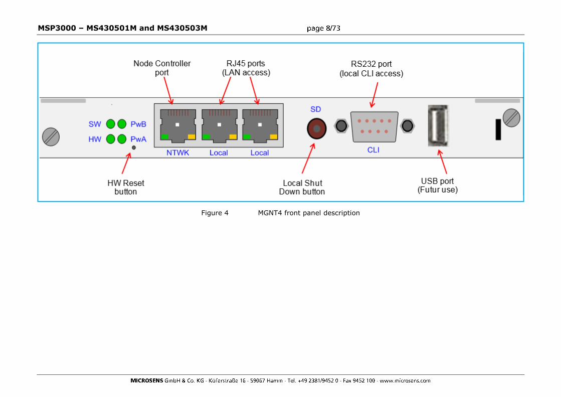
The Font panel description of the MGNT4 is given in Figure 4
The MGNT4 management unit has six main functions: It hosts the SNMP agent
It hosts the embedded web based http craft terminal
It hosts the console port giving access to the CLI (command Line Interface)
It provides three external Ethernet interfaces through an internal
Ethernet switch. o Two External Ethernet interfaces are used for connection to a
management network and for daisy chaining several chassis o The third External Ethernet interface is reserved for Node
Controller feature (future use).
It provides 6 internal Internal Ethernet interfaces dedicated to PM slots.
It provides the interface between the SNMP agent and the PM generic slots for managing the equipped PMs.
It provides the interface between the SNMP agent and the FAN unit.
The main characteristics of the MGNT4 management unit are:
Processor: 32 bit, 1.1 GHz
RAM memory: 512 Mbytes Flash memory: 512 Mbytes
Operating System: Linux
MSP3000 – MS430501M and MS430503M
Figure 3 2HU Chassis MGNT4 board block diagram
-48VA ETH1
Ethernet Switches
ETH2
Microprocessor
I²C
SPIdriver
I²Cdriver
-48V DC/DCConverter RS232
driverFlash
SPI
-48VB CLI
RAM
Ethernet Slot1 to Ethernet Slot6
PRSC1
To
PRSC6
PR
SC
_FA
N
RD
Y_
FA
N
HW
Fail
SW
Fail
Ch
assis
Pw
r o
n
Ch
assis
Failu
re
LEDs
E²PROM
Fu
seA
Fail
Fu
seB
Fail
FuseA
fail
FuseB
fail
RDY1
To
RDY6
ETH3
MSP3000 – MS430501M and MS430503M
FAN
The FAN hosts three separate fans with one power converter per fan. Each fan
generates a fan failure signal in event no rotation.
The FAN embeds also chassis monitoring features: o One synthesis alarm LED is dedicated to each slot of the chassis.
This synthesis alarm LED indicates if the module plugged in the associated slot is functional or not.
o Three severity alarms LED: A red LED for the Critical severity, an
orange LED for the Major severity and a yellow LED for the Minor severity. These three LEDs indicated if there is at least on
Critical/Major/Minor alarm detected in the complete chassis (including MGNT board, FAN and Pluggable Modules).
The FAN module is monitored by the management board plugged in slot 0.
Figure 5 Chassis FAN Unit block diagram
FAN3FAN2FAN1
-48VA
Micro-controller
I²C
SPIdriver
I²Cdriver
SPI
Fan
Failure
Dust
Filter
presence
LEDs
PR
SC
_FA
N
PR
SC
Du
st
Filte
r
FANDriver
SpeedcontrolE²PROM
Fail1 Fail2 Fail3
Tempsensor
-48VDCConvert
-48VDCConvert
-48VDCConvert
-48VB
MSP3000 – MS430501M and MS430503M
Aggregation and transport PMs
This section describes the management of the PM generic slots. Each PM generates its internal power supply from the two provided -48V.
The control bus from the MGNT to each PM generic slot is an SPI bus. Each PM
generic slot obtains its physical address from the IDENT pins in the backplane.
A ready (RDY) signal and a presence (PRSC) signal are sent from each PM
generic slot to the MGNT when it is ready for communication with the MGNT.
An Ethernet connection is also provided from each generic PM slot to the MGNT. It is used for getting Ethernet traffic from the PMs providing a DCC (Data
Communication Channel) transport.
MSP3000 – MS430501M and MS430503M
Interface Specifications
Power Supply
DC input power range:
minimum: -40.8V 1 maximum: -57.6V
1 there is an hysteresis of 7.2 Volts on the -40Volts. This means when plugging a
module in the chassis, the minimum voltage amplitude required is -48 Volts
AC input power range:
minimum: 85 VAC maximum: 265 VAC
Frequency range: 47-63 Hz
Ethernet/ SNMP
Ethernet 10/100/1000BASE-T interface
SNMP v2c over UDP transport.
CLI Port
RS232
MSP3000 – MS430501M and MS430503M
DC chassis Mechanical Description
Figure 6 DC Chassis front view
-48VA connector
-48VB connector
Dust Filter
FAN
MGNT
Slot 1
Slot 2
Slot 3
Slot 4
Slot 5
Slot 6
MSP3000 – MS430501M and MS430503M
AC version Mechanical Description
Figure 11 AC chassis front view
Dust Filter FAN MGNT
Slot 1
Slot 2
Slot 3
Slot 4
Slot 5
Slot 6
MSP3000 – MS430501M and MS430503M
Electrical and Environmental Conditions
Power Consumption
The power consumption for the regular chassis is 120 W typical without PMs in
generic slots.
Environmental
Regular Chassis
Ambient temperature range: 0°C to 50°C. humidity: 5-85%
storage temperature range: -20°C to +70°C
MSP3000 – MS430501M and MS430503M
Site Preparation Before installation ensure that your site meets the following requirements:
Mounting
With the mount kit provided, use a 19in (48.3cm) equipment rack, correctly grounded and secure.
The chassis may also be installed in a 23in or ETSI rack with the aid of
suitable extension brackets.
Access
Locate the chassis in a position that allows access to the front panel,
enabling maintenance, connection and visual checking.
Power Source
Provide a suitable power source within 9.8 feet (3 meters) from the location. The supplied cables are 3 meters in length.
Power specifications can be found in the technical Specification section of the present document.
Environment
Install the chassis in a suitable location with an ambient temperature of
0°C to 50°C and a maximum relative humidity of 85% Do not allow the air inlets to become obstructed, causing airflow restriction.
Keep 1.5 in (4 cm) free on both sides to ensure adequate ventilation.
MSP3000 – MS430501M and MS430503M
Delivery Verify the contents of the delivery. The basic delivery should consist of the
following;
One 2U subrack, containing: One Management card (MGNT)
One Fan unit (FAN) Two power cables (-48VDC for DC, 110/240 VAC for AC)
One Dust Filter One Rack-Mount installation kit
One set of documentation One to six generic slot PMs
Check your order for site specific equipment, number/type of modules etc. If any items are missing contact your supplier immediately.
Figure 16 DC chassis Front view
Figure 17 AC chassis Front view
-48VDC A -48VDC B MGNT FAN Dust filter
MGNT FAN Dust filter
MSP3000 – MS430501M and MS430503M
Installing the DC chassis
Rack mount Installation
Securely attach one rackmounting bracket on each side of the front of the chassis with the provided screws.
Align the mounting holes in the brackets with the holes in the rack and secure using the remaining screws in the supplied kit.
Warning
For a standard NEBS installation, the chassis must be installed in Network Telecommunication Facilities (Central
Offices)
MSP3000 – MS430501M and MS430503M
Grounding the chassis
Prior to power up the chassis, it is mandatory to ground the chassis.
Procedure
o Check that all the components are correctly seated and secured;
o It is recommended to apply an anti-oxidant compound to bare
conductors before any crimp connections are made for grounding
o The ground cable wire gauge has to be AWG12. Only copper cables shall be used for grounding purposes.
The ground cable ends are ringlet terminal lug (Thomas&Betts, Ref:
256-30685-1298) and two-hole compression lug.
o Connect one end of the ground cable to the ground reference
Warning
For a standard NEBS installation, the chassis must be grounded as part of the Common Bonding Network (CBN)
when installed in Network Telecommunication Facilities.
o Connect the other end to the dedicated two-hole lug that is provided on the rear frame of the chassis. The two-hole
compression lug must be screwed with star-washers to provide a locking mechanism.
End
MSP3000 – MS430501M and MS430503M
Powering up
There are two power inlets to enable backup in case of failure. The
second connection is optional. Before applying the power verify that the chassis is securely positioned and that the equipment and cables are not
damaged in any way.
There is no on/off switch on the chassis. Turning on and off the unit is
achieved by connecting and disconnecting the power lead(s).
Each -48V DC input (A&B) requires an independent external breaking circuitry. The minimum required distance between the contacts of this
breaking circuitry is 3 millimeters. The 0V Battery do not need any breaking circuitry
Breaking circuitry on -48VDC input A and -48VDC input B shall be off for powering off the chassis
Procedure
Using an On-Site -48V Supply:
- Check that all the components are correctly seated and secured;
- If cables are supplied, connect them to a correctly protected -48V
supply. Fuse Rating: 20A, as follows:
Red - 0V Battery Black - -48V
Wire Gauge - AWG14
MSP3000 – MS430501M and MS430503M
Power Cable Version 1
(for DC power connector Version 1)
Power Cable Version 2
(for DC power connector Version 2)
- The power cables ends are spade terminal lugs (Tyco, Ref: 52935)
- If you use your own cables, connect them to the 0V battery and -
48V as indicated on the power connector. Fuse rating is 20A, wire Gauge is AWG14
- Connect the other end to the power unit on the front panel of the
chassis: On the chassis with DC power connector Version 1, the
power cables can be connected using the cable terminal delivered in the installation kit a crossed screw
driver.
On the chassis with DC power connector Version 2 (spring cage connector), the power cables can be
connected using a flat screw drive to insert or extract the power cable into/from the sping cage connector.
Warning
It is recommended to treat the Battery Return Input Terminals as Isolated DC Return (DC-I).
- Make sure to route the power cable to the left side of the chassis.
MSP3000 – MS430501M and MS430503M
Figure 18 power cable routing (DC power connector Version 1)
Figure 19 power cable routing (DC power connector Version 2)
During the powering up sequence the HW led on the front panel of the
chassis will momentarily flash green before remaining on. One or two seconds later the SW led on the front panel will come on
indicating the correct loading of the software.
With normal led activity i.e. all leds on and green, the chassis is ready for setting up.
End
MSP3000 – MS430501M and MS430503M
Installing the AC chassis
Rack mount Installation
Securely attach one rackmounting bracket on each side of the front of the chassis with the provided screws.
Align the mounting holes in the brackets with the holes in the rack and secure using the remaining screws in the supplied kit.
Warning
For a standard NEBS installation, the chassis must be installed in Network Telecommunication Facilities (Central
Offices)
MSP3000 – MS430501M and MS430503M
Grounding the chassis
Prior to power up the chassis, it is mandatory to ground the chassis.
Procedure
o Check that all the components are correctly seated and secured;
o It is recommended to apply an anti-oxidant compound to bare
conductors before any crimp connections are made for grounding
o The ground cable wire gauge has to be AWG12. Only copper cables shall be used for grounding purposes.
The ground cable ends are ringlet terminal lug (Thomas&Betts, Ref:
256-30685-1298) and two-hole compression lug.
o Connect one end of the ground cable to the ground reference
Warning
For a standard NEBS installation, the chassis must be grounded as part of the Common Bonding Network (CBN)
when installed in Network Telecommunication Facilities.
o Connect the other end to the dedicated two-hole lug that is provided on the rear frame of the chassis. The two-hole
compression lug must be screwed with star-washers to provide a locking mechanism.
End
MSP3000 – MS430501M and MS430503M
Powering up
There are two power inlets to enable backup in case of failure. The
second connection is optional. Before applying the power verify that the chassis is securely positioned and that the equipment and cables are not
damaged in any way.
There is no on/off switch on the chassis. Turning on and off the unit is
achieved by connecting and disconnecting the power lead(s).
Each -48V DC input (A&B) requires an independent external breaking circuitry. The minimum required distance between the contacts of this
breaking circuitry is 3 millimeters. The 0V Battery do not need any breaking circuitry
Breaking circuitry on -48VDC input A and -48VDC input B shall be off for powering off the chassis
Procedure
Using an On-Site -48V Supply:
- Check that all the components are correctly seated and secured;
- Using standard 110/240VAC power cables, connect them to a
correctly protected 110/240VAC supply. Fuse Rating: 20A
- Connect the other end to the power unit on the front panel of the
Cchassis using the cable terminal delivered in the installation kit.
- Make sure to route the power cable to the left side of the chassis.
MSP3000 – MS430501M and MS430503M
During the powering up sequence the HW led on the front panel of the chassis will momentarily flash green before remaining on.
One or two seconds later the SW led on the front panel will come on indicating the correct loading of the software.
With normal led activity i.e. all leds on and green, the chassis is ready
for setting up.
End
System and Module Set-Up Management of the chassis can be achieved in a number of ways:
Locally and remotely:
The on-board SNMP agent allows the chassis to be managed from any system or PC in your network using network management software.
Consult the chassis user manual for information relating to the system
set-up.
MSP3000 – MS430501M and MS430503M
Preventive Maintenance
Dust Filter replacement Procedure
The dust filter should be visually examined on a six month basis.
Procedure
- Unscrew the locker and slide out the Dust filter located on the right of
the chassis
- Replace the dust filter
- Put back the dust filter grid and screw the locker.
- Check that the dust filter presence LED is green on the FAN front panel.
End
Figure 20 Dust filter lock mechanism
Lock Mechanism
MSP3000 – MS430501M and MS430503M
Corrective Maintenance
Management Board MGNT
MGNT Replacement Procedure
Use the following procedure to replace a MGNT management board:
Procedure
-Perform a chassis configuration backup.
-Get the inventory of the management board and store the release version of the management board.
MGNT boards are shipped with a management release loaded.
-Shutdown correctly the Test/SD button to the top position for 10
seconds (the 4 LEDs of the MGNT board will then shutdown).
Figure 21 MGNT Management board SD button
-Verify that the wrist strap you are wearing is properly grounded or that
other antistatic measures are in place.
-Disconnect any Ethernet cables from the Rj45 sockets on the front of
the board.
-Using a flat head screwdriver loosen the two holding screws on the frontplate, located at the top right-hand and bottom right-hand corners.
- Slide the MGNT Board out of the chassis, unplugging the backplane
connectors, and set aside.
-Line up the replacement MGNT Management Board with the lower rail and gently slide it in, plugging in the backplane connectors.
Note
Test Button
MSP3000 – MS430501M and MS430503M
Do not force the MGNT Board into place as this could lead to damage to the connectors on the module and/or the
connectors on the back panel of the chassis.
- Using a flat head screwdriver; tighten the two holding screws on the frontplate, located at the top right-hand and bottom right-hand corners.
-Re-connect Ethernet cables to the Rj45 sockets on the front panel.
-Observe behaviour of LEDs.
-Get the inventory of the management board
-Reload Software if required
-Verify status of MGNT Board.
-Verify communication with module(s).
-Perform a chassis configuration restore.
-Re-integrate the chassis into your network.
End
MSP3000 – MS430501M and MS430503M
Rescue CLI mode
The rescue CLI can be launched in case of major software crash on the
MGNT board to retrieve a working software. When the rescue CLI is activated, the following parameters are restored to
their default value:
Parameter Default value
SNMP
communities
SNMP Get: public
SNMP Set: private SNMP Trap: public
CLI passwords administrator: administrator
maintenance: maintenance
The rescue CLI allows the user to perform all the upgrade procedure described in the CLI documentation.
Use the following procedure to start the rescue CLI on the MGNT
management board:
Procedure
Use a needle-like tool (i.e. paper clip) to reach the MGNT reset button
and press it during 5 seconds minimum to activate the rescue CLI
feature.
Observe behaviour of MGNT LEDs. The colour sequence of the SW LED on the front panel of the MGNT is:
Off > Red > Green
The rescue CLI is then available through the RS232 port. Use the login “administrator” and the password “administrator” to log in
the rescue CLI.
The prompt “rescue_cli>” appears to indicate that the rescue CLI is currently running.
You can perform all the required upgrade or change the configuration of
the MGNT management board.
Perform a reset of the MGNT management board to quit the rescue CLI.
End
MSP3000 – MS430501M and MS430503M
FAN Unit
The following alarms indicate a problem with the Fan Unit:
mgnt2AlmFansFailure This bit indicates a failure on one of the fans (General).
mgnt2AlmPbFan1Fail This bit indicates a failure detected on Fan N°1.
Removal of the fan unit or rotation failure.
mgnt2AlmPbFan2Fail This bit indicates a failure detected on Fan N°2.
Removal of the fan unit or rotation failure.
mgnt2AlmPbFan3Fail This bit indicates a failure detected on Fan N°3.
Removal of the fan unit or rotation failure.
Note
If more than one Fan is out of service the FAN must be
replaced immediately.
Fan Unit Replacement Procedure
Note
It is not advisable to leave the chassis running for a
prolonged period without a working FAN in place. The maximum time without a working Fan Unit is 5 minutes in
an environment of 25°C.
Procedure
- Verify that the wrist strap you are wearing is properly grounded or that
other antistatic measures are in place.
- Using a flat head screwdriver loosen the holding screw on the frontplate, located at the bottom right-hand corner.
MSP3000 – MS430501M and MS430503M
-Pull the FAN out of the chassis, unplugging the backplane connectors,
and set aside.
-Line up the replacement module with the rails and gently slide in, plugging in the backplane connectors.
Note
Do not force the FAN into place as this could lead to damage to the connectors on the unit and/or the
connectors on the back panel of the chassis.
- Using a flat head screwdriver tighten the holding screw on the frontplate, located at the bottom right-hand corner.
-Verify correct operation of the FAN.
-Verify resolution of relevant alarms.
End
Module maintenance
Pluggable Module Replacement Procedure
Use the following procedure to replace a PM module:
Procedure
-Perform a chassis configuration backup.
-Get the inventory of the module and store the 5EK version of the
module.
- Verify that the wrist strap you are wearing is properly grounded or that other antistatic measures are in place.
-Take the necessary steps to minimise the impact on your network,
traffic by-pass re-route etc.
- Disconnect any cables connected to the Line and the client ports on the module.
MSP3000 – MS430501M and MS430503M
- Using a flat head screwdriver loosen the two holding screws on the frontplate.
-Pull the module out of the chassis, unplugging the backplane connectors, and set aside.
-Line up the replacement module with the rails and gently slide in,
plugging in the backplane connectors.
Note
Do not force the module into place as this could lead to
damage to the connectors on the module and/or the connectors on the back panel of the chassis.
-Re-connect cables to the Line and the client ports on the module.
-Observe behaviour of LEDs.
-Check the module has been correctly detected by the MGNT board
-Get the inventory of the module -Reload module Software if required
-Perform a chassis configuration restore.
-Re-integrate into your network.
End
MSP3000 – MS430501M and MS430503M
SFP/SFP+ Replacement Procedure
Each Client port based on SFP or SFP+ has its own LED located on the front panel of the PM to indicate operating status of each of the ports.
If a client port SFP/SFP+ needs to be replaced use the following procedure.
Procedure
Note
The SFP/SFP+ are hot-swappable therefore there is no requirement to power down the Module.
- Check the inventory to verify the type of SFP/SFP+ currently installed
-Take the necessary steps to minimise the impact on your network,
traffic by-pass re-route etc.
-Remove the Fibre Optic connector.
-Check the orientation of the SFP/SFP+ (to be sure to re-insert the new SFP/SFP+ with the same orientation)
-Release the SFP by: Carefully opening the latch or pressing the locking button and slide the SFP/SFP+ out of the module and place it aside.
-Gently push the SFP/SFP+ into the relevant module port until it is
securely seated. Take care to insert the SFP/SFP+ respecting the orientation checked
previously.
Note
Do not remove the protective caps from the SFP/SFP+
until you are ready to attach the fibre-optic.
-If Latch-Type SFP/SFP+; Close the latch to lock it into place.
-Clean Fibre Optic connectors on fibre optic cable.
-Re-connect Fibre.
-Verify correct operation of the SFP/SFP+.
End
MSP3000 – MS430501M and MS430503M
XFP Replacement Procedure
The Client or Line port based on XFP has two LEDs located on the front
panel of the PM; LOS and Fail, indicating operating status of each of the ports.
If a Line port XFP needs to be replaced use the following procedure:
Procedure
Note
The XFP’s are hot-swappable therefore there is no
requirement to power down the Module.
-Check the inventory to verify type of XFP currently installed
-Take the necessary steps to minimise the impact on your network,
traffic by-pass re-route etc.
-Remove the Fibre Optic connector.
-Check the orientation of the XFP (to be sure to re-insert the new XFP with the same orientation)
-Release the XFP by: Carefully opening the latch or pressing the locking
button and slide the XFP out of the module and place it aside.
-Gently push the XFP into the relevant module port until it is securely seated. Take care to insert the XFP respecting the orientation checked
previously.
Note
Do not remove the protective caps from the XFP until you
are ready to attach the network fibre-optic.
-If Latch-Type XFP; Close the latch to lock it into place.
-Clean Fibre Optic connectors on fibre optic cable.
-Re-connect Fibre.
-Verify correct operation of the XFP.
End
MSP3000 – MS430501M and MS430503M
CFP Replacement Procedure
The Client ports based on CFP have two LEDs located on the front panel
of the PM; LOS and Fail, indicating operating status of each of the ports.
If a Line or Client port CFP needs to be replaced use the following procedure:
Procedure
Note
The CFP’s are hot-swappable therefore there is no requirement to power down the Module.
-Check the inventory to verify type of CFP currently installed
-Take the necessary steps to minimise the impact on your network,
traffic by-pass re-route etc.
-Remove the Fibre Optic connector.
-Check the orientation of the CFP (to be sure to re-insert the new CFP
with the same orientation)
-Loosen the two holding screws on the CFP.
-Release the CFP and slide the CFP out of the module and place it aside.
-Gently push the CFP into the relevant module port until it is securely seated. Take care to insert the CFP respecting the orientation checked
previously.
Note
Do not remove the protective caps from the CFP until you
are ready to attach the network fibre-optic.
--Tighten the two holding screw on the CFP.
-Clean Fibre Optic connectors on fibre optic cable.
-Re-connect Fibre.
-Verify correct operation of the CFP.
End
MSP3000 – MS430501M and MS430503M
Initial Set-Up and Configuration
Configuration
Connecting to the manager
The chassis contains an on-board SNMP agent which allows it to be managed from any point in your network using network management
software. Access is via the RJ45 10 Mbit Ethernet port on the front panel.
Note
It is necessary to have the latest compiled MiB.
Verification of the connection can be achieved by sending a “ping”
message to the IP address of the chassis.
Each chassis is shipped the following default configuration
Parameter Default value
IP address 192.168.16.201
IP subnet Mask 255.255.255.0
IP manager List One manager address: 192.168.16.202
Gateway address 192.168.16.254 rank 1
192.168.16.254 rank 2
NTP server IP Address 0.0.0.0
Syslog Server IP Address
0.0.0.0
Chassis name NoName
SNMP communities SNMP Get: public SNMP Set: private
SNMP Trap: public
CLI passwords administrator: administrator maintenance: maintenance
Web passwords Admin: admin Operator: operator
Read-only: readonly
Once a connection is established to the chassis configuration may begin.
MSP3000 – MS430501M and MS430503M
Setting the chassis IP Address
The object
mgnt2GigmBoardIpAddress
Location: ...\microsens\mgnt2\mgnt2SNMPAgentData\ mgnt2IPmanagment
, can be used to define the chassis IP address in a manual way. In that
case, the DIP switches of the chassis Management Board must be all set to 0
or all set to 1.
Note
The MGNT board resets automatically in a warm manner to
apply the IP address modification
Setting the Chassis IP Subnet Mask
The object mgnt2GigmNetmask
Location: ...\microsens\mgnt2\mgnt21SNMPAgentData\mgnt2IPmanagm
ent
, defines the IP Subnet Mask of the Chassis.
Note
The MGNT board resets automatically in a warm manner to
apply the IP Subnet Mask modification
Setting the Chassis Gateways address
The MNGT can handle two different gateways to communicate over layer
3 network. These two gateways are linked to an order number to determine the main and the backup gateway.
By default the MGNT is using the gateways with the lowest order. If this gateway is dead, the MGNT switch to the other gateway. The dead
gateway detection is performed using a ping function. The estimated time to detect a dead gateway is less than 30 seconds.
The table
mgnt2GigmGatewayAddressTable
MSP3000 – MS430501M and MS430503M
Location: ...\microsens\mgnt2\mgnt2SNMPAgentData\mgnt2IPmanagme
nt
Contains the following objects mgnt2GigmGatewayAddress
mgnt2GigmGatewayOrder
These two objects allow the user to define two different gateways and
their order.
Note
The MGNT board resets automatically in a warm manner to apply any modification in the gateways configuration
Setting the Manager IP addresses
The IP address of the manager must be set to enable trap reception.
It is possible to set several managers IP address. In that case, all the managers specified in the manager list will receive all the traps sent by the
chassis To change the default IP address of the manager or add a new address,
the following object is concerned:
mgnt2GigmManagerIpAddressTable
Location: ...\microsens\mgnt2\mgnt2SNMPAgentData\ mgnt2IPmanagment
This table references three objects:
mgnt2GigmManagerIpIndex mgnt2GigmManagerIpAddress
mgnt2GigmManagerIpAddressTableRowStatus
It is possible to modify, add, remove or disable an IP address.
Warning
It is mandatory to keep always at least one entry in this
table.
Note
The Manager IP address manipulation can be changed off
site prior installation.
MSP3000 – MS430501M and MS430503M
Setting the chassis Name
The object: mgnt2GigmLogicalName,
Location: ...\microsens\mgnt2\mgnt2SNMPAgentData
, enables the user to assign a name to each chassis in the network,
(Alpha – numeric up to 255 characters).
This name may be used in maintenance work, i.e. to assist in locating a chassis.
Note
All alarms and traps originating from the chassis are accompanied by the IP address of the system not the
name.
Setting the SNMP Communities
The object:
mgnt2GigmRoCommunity , defines the SNMP Get community
mgnt2GigmRwCommunity
, defines the SNMP Set community.
Note
The object mgnt2GigmRwCommunity is not readable.
The returned value is always “*******”
mgnt2GigmTrapCommunity
, defines the SNMP Trap community
Location: ...\microsens\mgnt2\mgnt2SNMPAgentData\mgnt2Gigmsecurit
y
Note
A warm reset of the MGNT board is necessary to apply the
new communities
MSP3000 – MS430501M and MS430503M
Management
Inventory
An inventory check on the system returns the values of the following objects.
mgnt2RinvHwPlatform
Chassis management module: HW inventory.
Example Response:
MANAGEMENT HARDWARE Vendor: MICROSENS
Mnemonic: MGNT4 Part Number: 2EK00229ABAA01
Serial Number: 001000 Date Code (yymmddww): 13010901
mgnt2RinvSoftwarePackage
Software package identification.
Example Response: MANAGEMENT SOFTWARE
Mnemonic: Release 6.0.120
Part Number: 5MS02058AAAE01 Release date (yymmdd): 130201
mgnt2RinvGateware
Gateware identification.
Example Response: GW Part Number: 3GW000166AAAA
Version Number: 06 Release date (yymmdd):
mgnt2RinvAgent
Agent identification.
Example Response:
SW Part Number: 3SW02203AEAA Version Number: 17
Release date (yymmdd): 130322
mgnt2RinvCraft Agent identification.
Example Response:
CRAFT Part Number: 3SW03203AEAA Version Number: 08
MSP3000 – MS430501M and MS430503M
Release date (yymmddww): 130313
mgnt2RinvLinux
Agent identification.
Example Response: Linux Part Number: 3SW06001AAAA
Version Number: 24 Release date (yymmddww): 120619
Location: ...\microsens\mgnt2\mgnt2RemoteInventory
Alarms
In order to retrieve Alarm status information a polling mechanism must
be put in place. The appearance of a trap message signals the occurrence of an Alarm.
Location: ...\microsens\mgnt2\mgnt2Hardware\mgnt2alarms
The following table lists the possible MGNT alarms and recommended actions:
Name Description ACTION
mgnt2AlmAbsFailure
Chassis Management module failure :This OID indicates that the Chassis Management module is in fail conditio
Replace PBU-MGNT board, if Alarm persists.
mgnt2AlmFansFailure
Chassis Fan Module failure :This OID indicates that at least one of the three FAN unit of the FAN
module is in fail condition
Replace Fan Unit
mgnt2AlmDef48a
Power Input A present :This OID indicates that there is not input power on the right power connector (A)
Verify the power input A (power cord, power source)
mgnt2AlmDef48b
Power Input B present :This OID
indicates that there is not input power on the right power connector (B)
Verify the power input B (power cord, power source)
mgnt2AlmMgntDefFuseA
Mgnt Fuse A fail :This OID indicates that the fuse of the power input A is in fail condition on the Management
board
Correlate all alarms. If Alarm persists change the module.
mgnt2AlmMgntDefFuseB
Mgnt Fuse B Fail :This OID indicates that the fuse of the power input B is in fail condition on the Management board
Correlate all alarms. If Alarm persists change the module.
mgnt2AlmPmSlot2Absent PM present in Chassis slot 2 :This OID indicates the presence of a PM in Slot 2 of the Chassis .
Verify correct configuration.
MSP3000 – MS430501M and MS430503M
Name Description ACTION
mgnt2AlmPmSlot3Absent PM present in Chassis slot 3 :This OID indicates the presence of a PM in Slot 3 of the Chassis .
Verify correct configuration.
mgnt2AlmPmSlot4Absent PM present in Chassis slot 4 :This OID indicates the presence of a PM in Slot 4 of the Chassis .
Verify correct configuration.
mgnt2AlmPmSlot5Absent PM present in Chassis slot 5 :This OID indicates the presence of a PM
in Slot 5 of the Chassis .
Verify correct configuration.
mgnt2AlmPmSlot6Absent
PM present in Chassis slot 6 :This
OID indicates the presence of a PM in Slot 6 of the Chassis .
Verify correct configuration.
mgnt2AlmPmFanAbsent FAN module present in Chassis :This OID indicates the presence of
the FAN module in the Chassis
Insert a PBU-FAN in the chassis
mgnt2AlmPbFan1Fail
Fan unit n°1 failed on Fan module :This OID indicates a failure on fan 1. Removal of the fan unit or no
rotation sets the OID.
Replace the Fan Unit
mgnt2AlmPbFan2Fail
Fan unit n°2 failed on Fan module :This OID indicates a failure on fan
2. Removal of the fan unit or no rotation sets the OID.
Replace the Fan Unit
mgnt2AlmPbFan3Fail
Fan unit n°3 failed on Fan module :This OID indicates a failure on fan 3. Removal of the fan unit or no rotation sets the OID.
Replace the Fan Unit
mgnt2AlmPbFan4Fail
Fan unit n°4 failed on Fan module
:This OID indicates a failure on fan 4. Removal of the fan unit or no rotation sets the OID.
Replace the Fan Unit
mgnt2AlmPbFan5Fail
Fan unit n°5 failed on Fan module :This OID indicates a failure on fan 5. Removal of the fan unit or no rotation sets the OID.
Replace the Fan Unit
mgnt2AlmPbFan6Fail
Fan unit n°6 failed on Fan module :This OID indicates a failure on fan 6. Removal of the fan unit or no rotation sets the OID.
Replace the Fan Unit
mgnt2AlmFanPwrProtOn Fan Backup Power :This OID indicates the backup power on the FAN module is switched on
Replace the Fan Unit
mgnt2AlmFanPwrFail1
Fan Main Power :This OID indicates
a failure on the main power of the FAN module
Correlate all alarms. If Alarm
persists change the module.
mgnt2AlmFanDefFuseA Fan Fuse A fail :This OID indicates that the fuse of the power input A is in fail condition on the Fan board
Correlate all alarms. If Alarm persists change the module.
mgnt2AlmFanDefFuseB Fan Fuse B Fail :This OID indicates that the fuse of the power input B is
in fail condition on the Fan board
Correlate all alarms. If Alarm persists change the module.
mgnt2AlmApiError
Comm fail between Agent and PMs :This OID indicates a failure
detected on the Agent.The failure is located on a communication process with the modules.
-Correlate other alarms and
Traps. -Reset the Management board.
MSP3000 – MS430501M and MS430503M
Name Description ACTION
mgnt2AlmFifoCmdError
SNMP Agent to PM comm FIFO fail :This OID indicates a failure inside the FIFO stack. The FIFO containing the messages from the agent (write) to the PMs is full
-Correlate other alarms and Traps. -Reset the Management board.
mgnt2AlmapiErrorCode API Error Identification :Error number and description of the abs1AlmApiError object
See API error table
mgnt2AlmLogFileFull
Log File Full Alarm :This OID indicates that a log file is full. This file must be cleared to insure correct log function
Reset the log file to insure correct working of the log function
mgnt2AlmLog80Full Log File Full Warning :This OID indicates that a log file is 80% full.
Check the log files
Table 1 MGNT Alarms list
MSP3000 – MS430501M and MS430503M
Traps
A trap is an unsolicited, asynchronous event that the chassis generates to indicate a status changes; e.g.: a trap is generated on the detection of
a start of an alarm and an end of an alarm.
Note
It is important to set the IP address of the manager correctly in order to receive the traps.
The following table lists the possible traps originating from the MGNT Board:
MGNT Traps
Name Possible cause Action
Description
mgnt2TrapApi See API Code Table
Reboot the agent (Warm
Reset).
Api error trap with its number
mgnt2TrapSwError Fault in SNMP Agent write
operation, resulting in an
unsuccessful set
operation.
Reboot the agent (Warm
Reset).
MGNT software error other API
mgnt2TrapHwError Fan failure (Fan number
indicated in the trap
message)
Carry out relevant maintenance
procedure. MGNT hardware error
mgnt2TrapBoardInserted A PM module has been
inserted No action, information only
PM module inserted
mgnt2TrapBoardRemoved A PM module has been
removed No action, information only
PM module removed
mgnt2TrapRestoreConfDone The configuration of the
PM has been restored
with the one stored in the
MGNT
No action, information only
PM Configuration restored
mgnt2TrapGlobalPowerFail There is no power cable
connected on the power
connector of the chassis
No action, information only One power input is in fail
condition
mgnt2TrapLogFileFull One of the log files is
either full or 80% full.
Check the log file and reset
them to insure the correct
working if this log function One of the log file is full or 80%
full
Table 2 MGNT Traps list
MSP3000 – MS430501M and MS430503M
API Codes
The following table lists the API codes that can accompany specific Alarms and Traps. The information codes are not errors; the API
indicates the state of communication with the module as information. Name Description Value
API Information Codes
DEF_API_OK Default Value 0
DEF_API_COLD_RESET_MODULE Cold Reset request 4
DEF_API_WARM_RESET_MODULE Warm Reset request 5
DEF_API_DOWNLOAD_IN_PROGRESS Download in Progress 3
API Error Codes
moduleNotResponding A timeout occurred on requested
response of a command
128
messageFormatError The module has detected a wrong
message format
129
cmdExecutionError Internal module error during the
processing of a message
130
unknownArticleError The article is unknown or not allowed 132
unknownMessageError The message is unknown or not
allowed
133
Table 3 API error code
Control
There are six objects associated with the control function.
Location:...\microsens \mgnt2\mgnt2Hardware\mgnt2controls\
They are responsible for:
mgnt2CtrlGigamixWarmReset
This bit allows resetting the MGNT in a 'warm' manner. A warm reset does not affect the traffic, the module configuration
remains unchanged.
mgnt2CtrlChassisShutDown
This bit must be set to two to shut down the chassis in a correct manner. Once the OID has been set, it is necessary to wait for 5
seconds before removing the power of the chassis.
mgnt2CtrlEthPort2Disable This bit enables/disables the second Ethernet Port on the MGNT
(right port).
Note
When not required it is advised to disable this port in order
to avoid unauthorised connection.
MSP3000 – MS430501M and MS430503M
mgnt2CtrlGreenLed
This bit switches ON all the green LEDs of the chassis (MGNT, FAN and all the PMs plugged in the chassis)
mgnt2CtrlRedLed
This bit switches ON all the red LEDs of the chassis (MGNT, FAN and all the PMs plugged in the chassis)
mgnt2CtrlLedOff
This bit switches OFF all the LEDs of the chassis (MGNT, FAN and all the PMs plugged in the chassis)
MSP3000 – MS430501M and MS430503M
Software Management
Resets
The following describes the various methods of resetting the MGNT board;
Note
Under no circumstances should a Reset be attempted
during the Installation Phase of the SNMP Agent Update procedure.
Consult the object:
mgnt2PackageExtractionInProgress. Ensure it is set to “off” before continuing.
Warm reset
This reset has no effect on the traffic and takes 35 seconds to complete.
Procedure
-Start the reset:
Set to “on “the object: mgnt2CtrlChassisWarmReset
Location:
…\microsens\mgnt2\mgnt2Hardware\mgnt2controls\mgnt2Ctrlsynth5\
Visual indication:
The colour sequence of the SW LED on the front panel of the MGNT during a warm reset is:
Green > Red (few seconds) > Orange (less than 1 second) > Green
Under normal conditions all LEDs return to green when the reset is
complete. Refer to LED status table in Appendix A. The duration of a MGNT warm reset is approximately 35 seconds, during
which time the management function is unavailable.
End
MSP3000 – MS430501M and MS430503M
Hardware reset
A hardware reset may be also performed on the MGNT.
This reset has no effect on the traffic and takes 35 seconds to complete.
Procedure
-Use a needle-like tool (i.e. paper clip) to reach the MGNT reset button
and press it during 1 second to perform a hardware reset of the MGNT.
Figure 23 MGNT4 Management board Reset button
Visual indications:
The colour sequence of the front panel LEDs are:
HW LED: Red (while the reset button is pressed) > Green SW LED: Off (few seconds) > Orange (less than 1 second) > Green
Under normal conditions all LEDs return to green when the reset is complete. Refer to LED status table in Appendix
The duration of a MGNT warm reset is approximately 35 seconds, during which time the management function is unavailable.
End
Reset Button
MSP3000 – MS430501M and MS430503M
MGNT Unplug/Plug
Another method of reset is to unplug/uinplug the MGNT
This reset has no effect on the traffic and takes 35 seconds to complete.
Procedure
Before the extraction of the MGNT, it is mandatory to power it down.
-MGNT Software stop:
Before unplug the MGNT, it is mandatory to stop the MGNT software.
There are several ways to stop the MGNT software: Using the test button on the front panel
Push up the test button for 10 seconds.
Using a SNMP objet Set the object mgnt2CtrlChassisShutDown
Location: ...\microsens \mgnt2\mgnt2Hardware \mgnt2controls\
Using a command in the CLI
Enter the command shutdown (or sd) in the CLI.
In all the cases, the LEDs of the MGNT are switched OFF when the MGNT is properly stopped.
Then, you can unplug the MGNT and plug it again in the chassis.
Note
It is necessary to wait at least 10 seconds before plugging again the MGNT
Visual indications: The colour sequence of the front panel LEDs are:
MGNT
SW LED: Off (few seconds) > Orange (less than 1 second) > Green HW LED: Red (about 1 second) > Green
End
MSP3000 – MS430501M and MS430503M
Power Off/On
The last method of reset is to power down the chassis for a few moments and power up again. This is traffic affecting and all equipped
modules are reset. The manager is unavailable for approximately 35 seconds
Procedure
There is no on/off switch on the chassis, powering down/up is achieved by disconnecting/connecting the -48V supply(s) on the front panel.
-Power Down: Before powering down the complete chassis, it is mandatory to stop the
MGNT software. There are several ways to stop the MGNT software:
Using the test button on the front panel Push up the test button for 10 seconds.
Using a SNMP objet
Set the object mgnt2CtrlChassisShutDown Location: ...\microsens \mgnt2\mgnt2Hardware
\mgnt2controls\
Using a command in the CLI Enter the command shutdown (or sd) in the CLI.
In all the cases, the LEDs of the MGNT are switched OFF when the MGNT is properly stopped.
Remove the -48V supply(s) on the front panel.
-Power Up: Connect the -48V supply(s) on the front panel.
Visual indications:
The colour sequence of the front panel LEDs are:
MGNT SW LED: Off (few seconds) > Orange (less than 1 second) > Green
HW LED: Red (about 1 second) > Green
End
MSP3000 – MS430501M and MS430503M
Module management
Module detection
Information regarding the number of generic slot PM and their configuration in the chassis may be obtained via the table:
mgnt2GigmBoardTable
Location:
…\microsens\mgnt2\mgnt2SNMPAgentData\mgnt2ModulesManagement\
Example:
1: mgnt2IndexBoards.0 (integer) 0 2: mgnt2Position.0 (integer) 3
3: mgnt2Name.0 (octet string) pm1008 4: mgnt2PortNumber.0 (integer) 8
5: mgnt2LineNumber.0 (integer) 1
Where: mgnt2Position returns the physical position of the module(s).
mgnt2Name returns the name of the module mgnt2PortNumber Number of ports on the module
mgnt2LineNumber Number of lines on the module
The following diagram shows the slot positions:
The object:
mgnt2GigmSelectedBoard
Location: …\microsens\mgnt2\mgnt2SNMPAgentData\mgnt2ModulesManagement\
allows the user to select the module to manage using the slot number.
Note
Before performing any operations on a module it is
necessary to consult this object beforehand to ensure that the correct module is selected.
Slot 1
Slot 2
Slot 3
Slot 4
Slot 5
Slot 6
MSP3000 – MS430501M and MS430503M
There are also alarms originating from the MGNT which are associated with the generic slot PM modules. These alarms indicate the presence or
absence of a module in a particular slot.
Example:
1: mgnt2AlmPmSlot2Absent.0 (integer) off (1) 2: mgnt2AlmPmSlot3Absent.0 (integer) on (2)
3: mgnt2AlmPmSlot4Absent.0 (integer) on (2) 4: mgnt2AlmPmSlot5Absent.0 (integer) on (2)
5: mgnt2AlmPmSlot6Absent.0 (integer) on (2)
In the above example we can see that this particular chassis is equipped
with one Module which is located in slot 3.
Generic slot PM Backup configuration
Note
In all the following procedures, the user has the possibility
to delete some files from the FLASH and/or the RAM
memory. It is necessary to delete only one file at a time to ensure a correct delete process.
Upload a configuration
A user may upload the configuration of a PM module to a PC via the
MGNT management board. The user gets the PM configuration in an XML-like file.
To achieve this, you will need:
An SNMP V2C browser (for reading and updating values in the MIB)
A TFTP client
The configuration uploading procedure is carried out in three phases:
1. Create a backup file of PM configuration in the FLASH memory
(conf partition) of the MGNT management board. 2. Transferring the backup file from the MGNT FLASH memory to
the MGNT RAM memory 3. Get the backup file in the MGNT RAM memory via a TFTP
command.
Described in more detail as follows:
MSP3000 – MS430501M and MS430503M
Procedure
1. Create a backup file The object of this phase is to read the configuration of a dedicated PM
module and store this configuration in a backup file.
- Use your SNMP browser to check the backup file presence in the FLASH memory of the MGNT management board using the table:
mgnt2CnfManageConfigFilesTable
Location: …\microsens\mgnt2\mgnt2ConfigManagement
There is one dedicated backup file for each chassis Slot. At this stage in the procedure, there should be no file in the FLASH memory.
- create a backup file of configuration by setting
mgnt2CnfBackupConfig
Location:…\microsens\mgnt2\mgnt2ConfigManagement\ mgnt2CnfManageConfigFilesTable
, linked to the dedicated PM module. The PM module is referenced by the
slot number where it is plugged in.
At this moment, a backup file is created in the FLASH memory of the MGNT management board.
Note
The backup file name is respecting the following format:
bkpConf + ‘slot number’ For instance, the backup file of the module plugged in slot
5 will have the following name: bkpConf05
- Use your SNMP browser to check the backup file presence in the FLASH
memory of the MGNT management board using the table: mgnt2CnfManageConfigFilesTable
Location: …\microsens\mgnt2\mgnt2ConfigManagement
Note
From this point the maintenance configuration feature is enabled. It means that if a new PMxxxx module is plugged
in the slot number pointed by the backup file, the MGNT
MSP3000 – MS430501M and MS430503M
management board will performed the following process:
- Check if the backup file is compatible with the PMxxxx module plugged in (i.e. same number of line
ports and same number of client ports) - If the compatibility is correct, the backup file
configuration will be automatically transferred to the PM module.
2. Transferring the backup file
The object of this phase is to transfer the backup file from the FLASH memory to the RAM memory of the MGNT management board.
- Use your SNMP browser to check the backup file presence in the RAM memory of the MGNT management board using the table:
mgnt2CnfUploadConfigFilesTable
Location: …\microsens\mgnt2\mgnt2ConfigManagement
There is space to store four configuration files in The RAM memory. At this stage in the procedure, there should be no file in the RAM memory.
If there is no free space anymore in the RAM memory, you may delete a
backup file from the RAM memory using the object mgnt2CnfDeleteConfigFile
Location:...\microsens\mgnt2\mgnt2ConfigManagement\
mgnt2CnfUploadConfigFilesTable
- Export the backup file previously created in the FLASH memory to the
RAM memory using the object: mgnt2CnfExportConfig
Location:...\microsens\mgnt2\mgnt2ConfigManagement\
mgnt2CnfManageConfigFilesTable
- Use your SNMP browser to check the backup file presence in the RAM
memory of the MGNT management board using the table: mgnt2CnfUploadConfigFilesTable
Location: …\microsens\mgnt2\mgnt2ConfigManagement
The backup file is now located in the RAM memory and is accessible via a TFTP command.
MSP3000 – MS430501M and MS430503M
3. Get the backup file
The object of this phase is to get the backup file in the RAM memory of the MGNT management board.
- Open a Command Line Interface window from your operating system
and go to the directory where you want to store the backup file.
- Enter the line (Windows XP):
T:\home\> tftp -i 192.168.16.123 GET /tftpboot/bkpConfxx destfile.txt
Where: T:\home – is the location where you want to store the file on your
PC
bkpConfxx - is the name of the backup file in the RAM memory (xx stands for the slot number where the PMxxxx module is
plugged in) destfile.txt – is the name of the destination file on you PC
192.168.16.123 - is the IP address of the chassis into which the package is to be loaded.
Note
Return of the prompt indicates completion of upload.
At this moment, the configuration file has been transfered on your PC. It is now possible to upload this file in various chassis to configure several
PM modules identical to the source one.
End
Downloading a configuration
A user may download a configuration file to the MGNT management
board and apply this configuration to a PM module.
To achieve this, you will need:
An SNMP V2C browser (for reading and updating values in the MIB) A TFTP client
The configuration downloading procedure is carried out in three phases:
1. Remote loading of the configuration file via TFTP into the chassis 2. Transferring the backup file to FLASH memory
3. Activation of the configuration in the PM module. Described in more detail as follows:
MSP3000 – MS430501M and MS430503M
Procedure
1. Remote loading
The object of this phase is to load the configuration file into the RAM of the MGNT management board
For this example, the configuration file will be called “config” on the PC
-Verify that there is still free space in the RAM memory of the MGNT management board using the following object
mgnt2CnfUploadConfigFilesTable
Location: …\microsens\mgnt2\mgnt2ConfigManagement
There is space to store four configuration files in The RAM memory.
If there is no free space anymore in the RAM memory, you may delete a backup file from the RAM memory using the object
mgnt2CnfDeleteConfigFile
Location:...\microsens\mgnt2\mgnt2ConfigManagement\ mgnt2CnfUploadConfigFilesTable
- Open a Command Line Interface window from your operating system and go to the directory where you placed the new package.
- Enter the line (Windows XP):
T:\home\> tftp -i 192.168.16.123 PUT config /tftpboot/config
Where: T:\home – is the location of the package on your PC
config - is the name of the configuration file you wish to download and
192.168.16.123 - is the IP address of the chassis into which the package is to be loaded.
Note
Return of the prompt indicates completion of download.
MSP3000 – MS430501M and MS430503M
- Check that your configuration file is loaded correctly by consulting the
table: mgnt2CnfUploadConfigFilesTable
Location: …\microsens\mgnt2\mgnt2ConfigManagement
, and verify that your file is located in this table, check the filename of
your file with the value of: mgnt2CnfConfigFileName
Your configuration file is now in the RAM memory and ready for transferring to the FLASH memory of the MGNT management board.
2. Transferring
The object of this phase is to transfer the configuration file previously loaded into the RAM to the FLASH
- Use your SNMP browser to check the backup file presence in the FLASH
memory of the MGNT board using the table: mgnt2CnfManageConfigFilesTable
Location: …\microsens\mgnt2\mgnt2ConfigManagement
Note
If there is already a backup file dedicated to your target PM module, the file will be overwritten with the new
backup configuration file.
Since each backup file present in the FLASH memory is dedicated to a slot number, it is necessary to specify the target slot number of the
configuration file before transferring it from the RAM memory to the FLASH memory.
- Specify the target slot number using the object
mgnt2CnfConfigSlot associated with the required configuration file.
Location:...\microsens\mgnt2\mgnt2ConfigManagement\ mgnt2CnfUploadConfigFilesTable
-Set to “on” the object: mgnt2CnfConfigUpload associated with the required configuration
file.
Location:...\microsens\mgnt2\mgnt2ConfigManagement\
mgnt2CnfUploadConfigFilesTable
MSP3000 – MS430501M and MS430503M
This validates the transfer of the configuration file to the FLASH memory with a dedicated target slot number.
During this transfer, the filename of the configuration file is modified to fit to the following format: bkpConf + ‘slot number’. For instance, if the
file “config” is transferring to the FLASH memory and dedicated to the slot 3, it will be renamed and called: bkpConf03.
- Use your SNMP browser to check the backup file presence in the FLASH memory of the MGNT management board using the table:
mgnt2CnfManageConfigFilesTable
Location: …\microsens\mgnt2\mgnt2ConfigManagement
, and verify that the configuration file has been transferred, renamed and
associated to the correct slot number.
Note
The same configuration file can be used to create several
backup files, each one dedicated to a single slot. If it is the case, repeat the step 2.Transferring as much as
necessary.
Note
From this point the maintenance configuration feature is
enabled. It means that if a new module is plugged in the slot number pointed by the backup file, the MGNT
management board will performed the following process:
- Check if the backup file is compatible with the PM module plugged in (i.e. same number of line ports
and same number of client ports) - If the compatibility is correct, the backup file
configuration will be automatically transferred to the PM module.
3. Activation
The object of this phase is to activate the backup configuration on the PM
module.
- First, check there is a module in the dedicated slot using the object mgnt2GigmBoardTable
MSP3000 – MS430501M and MS430503M
Location: ...\microsens\mgnt2\mgnt2SNMPAgentData\ mgnt2ModulesManagement
If the module is present, then it is possible to activate the backup
configuration on the PM module.
-Set to “on” the object:
mgnt2CnfRestoreConfig associated with the required backup file
Location: ...\microsens\mgnt2\mgnt2ConfigManagement\ mgnt2CnfManageConfigFilesTable
The MGNT management board will check the compatibility between the
backup configuration file and the target PM module. The compatibility is based on the number of line ports and the number of client ports.
If the backup file and the PM module are compatible, the configuration is
transferred to the PM module and stored in the Configuration 2 in the FLASH memory of the PM module.
It is recommended to perform a cold reset on the PM module to apply
definitively the new configuration.
Note
The cold reset is necessary only if the start-up
configuration has been modified.
End
MSP3000 – MS430501M and MS430503M
Summary block diagram
Pluggable Module
RAM
FLASH
FLASH
management
board
management
computer TFTP PUT
TFTP GET
Up
loa
d
Ba
ck
up
Ex
po
rt
Res
tore
MSP3000 – MS430501M and MS430503M
Laser Class Laser
Class
Risks
General Requirements
1 Considered safe to eye and Skin under all
reasonably foreseeable conditions of
operation.
● Protective housing: may be
required.
MSP3000 – MS430501M and MS430503M
Appendix Chassis Leds description Location LED Status Condition
MGNT
Pwr A
Green On The Power input A (left connector) is valid
Red On The Power input A (left connector) is in fail
condition
Pwr B
Green On The Power input B (right connector) is
valid
Red On The Power input B (right connector) is in
fail condition
SW
Green On Normal
Red On Reset in Progress
Orange on Initialization
HW
Green On Normal
Red On Hardware Error (On During Powering Up)
FAN
Pwr A
Green On The Power input A (left connector) is valid
Red On The Power input A (left connector) is in fail
condition
Pwr B
Green On The Power input B (right connector) is
valid
Red On The Power input B (right connector) is in
fail condition
SW
Green On Normal
Red On Reset in Progress
Orange on Initialization
HW
Green On Normal
Red On Hardware Error
(On During Powering Up)
FAN Fail Red Off The FAN is in normal condition
Red On The FAN is in fail condition
Filter Presence Green On The Dust Filter is present
Green Off The Dust Filter is absent
Critical Red On At least one critical alarm on the chassis
Red Off No critical alarm on the chassis
Major Orange On At least one major alarm on the chassis
Orange Off No major alarm on the chassis
Minor Yellow On At least one minor alarm on the chassis
Yellow Off No minor alarm on the chassis
PM LED
Green On There is no alarm on the PM
Red On There is at least on alarm on the PM
Off The PM is absent or passive