7
920-107C-EN TUBE INSPECTION SYSTEM MultiScan MS 5800 Series • Condensers • Feedwater Heaters • Heat Exchangers • Air Conditioners • Boilers • Air Coolers

920-107C-EN
TUBE INSPECTION SYSTEM
MultiScan MS 5800 Series
• Condensers• FeedwaterHeaters• HeatExchangers• AirConditioners• Boilers• AirCoolers

2
Conductive and nonferromagnetic tube material
Impedance bridge coils, absolute/differential
Magnetic field
Eddy currents
MultiScan MS 5800 E™
Tube Inspection with Eddy Current Testing (ECT)• Condensers• Feedwater heaters• Heat exchangers• Air conditioners
MULTISCAN MS 5800E KEY FEATURES• 4 simultaneous frequencies per input.
This feature allows inspection speeds up to 2 m/s with 4 frequencies on absolute and differential channels, without signal distortion.
• Electronic probe balancing.No separate external reference probe is required for absolute channel operation.
• 4 ECT inputs and up to 64 multiplexed channels.The MultiScan™ MS 5800E can support a large number of ECT channels to perform array probe inspections. Compared to single-channel inspection, the array probe technology allows faster and easier surface coverage.
ECT APPLICATIONSEddy current testing is a noncontact method used to inspect nonferromagnetic tubing. This technique is suitable for detecting and sizing metal discontinuities such as corrosion, erosion, wear, pitting, baffle cuts, wall loss, and cracks in nonferrous materials.
• Two coils are excited with an electrical current, producing a magnetic field around them. The magnetic fields penetrate the tube material and generate opposing alternating currents in the material. These currents are called eddy currents.
• Any defects that change the eddy current flow also change the impedance of the coils in the probe.
• These changes in the impedance of the coils are measured and used to detect defects in the tube.

3
Synchronization pin Rotor is propelled by water pressure
Tube is flooded with water
UT beam is reflected by tube inner and outer walls
Turbine body
MultiScan MS 5800 U™
Tube Inspection with Internal Rotating Inspection System (IRIS) for Ferrous and Nonferrous Materials• Boilers• Feedwater heaters• Air coolers• Heat exchangers
MULTISCAN MS 5800U (IRIS) KEY FEATURES• Setup wizard
Simplifies equipment calibration for different tube diameters and materials. The wizard also generates the reporting code for the inspection.
• Real-time gain and gate controlsUT settings can be modified during the C-scan acquisition to quickly optimize signal detection.
• Real-time and continuous color C-scansReduces missed flaws with C-scan displays. Enhance the quality and appearance of your reports by including color maps and cross-section views of defects.
• Full tube-length recordingUsed to analyze data offline and assess results with the customer.
IRIS APPLICATIONSThe ultrasonic IRIS option is used to inspect a wide range of ma-terials including ferrous, nonferrous, and nonmetallic tubing. This technique detects and sizes wall loss resulting from corrosion, erosion, wear, pitting, cracking, and baffle cuts. Olympus digital IRIS inspection technology is used extensively as a prove-up tech-nique for remote field testing, magnetic flux leakage, and eddy current inspections.

4
Absolute response
Differential response
Indirect or remote field
Magnetic flux lines
Driver coil Pickup coils, absolute/differential
Single-driver model shown
Transition zoneDirect field
RFT probes come in different sizes and configurations to suit most applications.
TRC Series Flexible Boiler
Large diameter TRX Series Dual Driver
TRS Series Single Exciter
TRT Series Dual Pickup
TRX Series Dual Exciter
MULTISCAN MS 5800R KEY FEATURES (RFT)• RFT with up to four different frequencies and real-time mixes.
This feature allows more flexibility for mixing and defect validation. The detection and sizing of flaws at the support plate becomes easier with multifrequency inspections and dual-driver operations.
• RFT with frequencies ranging from 20 Hz to 250 kHz. The high frequency available with the MultiScan MS 5800R™ extends the RFT inspection to thin materials with low permeability, such as the stainless steel 400 series and other ferromagnetic alloys.
MultiScan MS 5800 R™
Tube Inspection with Remote Field Testing (RFT) • Boilers• Feedwater heaters• Carbon steel heat exchangers
REMOTE FIELD TESTING APPLICATIONSRemote field testing (RFT) is being used to successfully inspect ferromagnetic tubing such as carbon steel or ferritic stainless steel. This technology offers good sensitivity when detecting and measuring volumetric defects resulting from erosion, corrosion, wear, and baffle cuts.
Olympus remote field probes and the MultiScan™ MS 5800 are used to successfully inspect heat exchangers, feedwater heaters, and boiler tubes, around the world.

5
Aluminum-finned carbon-steel tube
Trail pickupDriver coil
Differential channel
Lead pickup (absolute channel)
Magnetic flux and eddy currents are restricted to tube ID
MFL display
NFT display
TFB Series high-saturation MFL probe
TRD Series NFT probe
Axially oriented saturating magnetic field
Trail pickup coils, differentialLead pickup coils, absolute/differential Sturdy probe cable
Powerful neodymium-iron-boron permanent magnet set
MultiScan MS 5800 R™
Tube Inspection with Magnetic Flux Leakage (MFL)• Feedwater heaters• Air coolers• Carbon steel heat exchangers
MAGNETIC FLUX LEAKAGE APPLICATIONSMagnetic flux leakage (MFL) is a fast inspection technique, suit-able for measuring wall loss and detecting sharp defects such as pitting, grooving, and circumferential cracks. MFL is effective for aluminum-finned carbon steel tubes because the magnetic field is almost completely unaffected by the presence of such fins.
Tube Inspection with Near Field Testing (NFT)• Air coolers• Carbon steel heat exchangers
NEAR FIELD TESTING APPLICATIONSThe near field testing (NFT) technology is a rapid and inexpen-sive solution intended specifically for fin-fan carbon-steel tubing inspection. This new technology relies on a simple driver-pickup eddy current probe design providing very simple signal analysis.
NFT is specifically suited for the detection of internal corrosion, erosion, or pitting on the inside of carbon steel tubing. The NFT probes measure lift-off or “fill factor” and convert it to amplitude-based signals (no phase analysis). Because the eddy current pen-etration is limited to the inner surface of the tube, NFT probes are not affected by the fin geometry on the outside of the tubes.

6
MultiView™
VOLTAGE PLANE ANALYSIS FEATURES• Voltage plane theoretical curve• Circumferential sizing overlay• Calibration of three depth curves with only one reference
point• Voltage plane calibration without a support-plate signal• Dual-driver software control
ULTRASOUND ANALYSIS FEATURES• Offline cylindrical view• Pit-depth measurement cursors• Display of wall loss (%) and remaining wall• Real-time C-scan acquisition
MultiView ™/T
TUBE ANALYSIS SOFTWARE OPTION• Phase-to-depth and voltage-to-depth sizing curves• Computer-assisted analysis• Tabular report entries and report generation
CARTO™
INSPECTION PLANNING AND TUBESHEET MAPPING
• Database management of exchangers, reports, and tubesheet maps
• Graphical tools for the creation of tubesheet maps and inspection lists
• Storage of all reports and tubesheet maps in database• Display of results from single or multiple reports
Software features (ECT/RFT/MFL/UT)
Setup wizard Easy configuration for tube inspec-tion with conventional probes
Automatic calibration Simultaneous calibration of all channels and depth curves
Data file storage Any PC-compatible media
Printing Screen dump, acquisition, and setup reports to any Microsoft®
Windows XP®–compatible printer
Software features (UT)
Measurement mode Wall thickness: IRIS (immersion)
Setup display A-scan
Profilometry display Wall thickness, ID and OD color C-scans, B-scan for tube circum-ferential cross section and axial section
Cursors Cross-section cursors and manual pit-sizing cursors
Measurement Wall loss (%), remaining wall, and statistics on tube geometry (minimum, maximum, average)
Software requirements
Operating system Microsoft Windows XP Pro
Hardware requirements 2 GHz Pentium® with 2 GB RAM, 1 GB of free space on a hard disk, 1024 × 768 display resolution
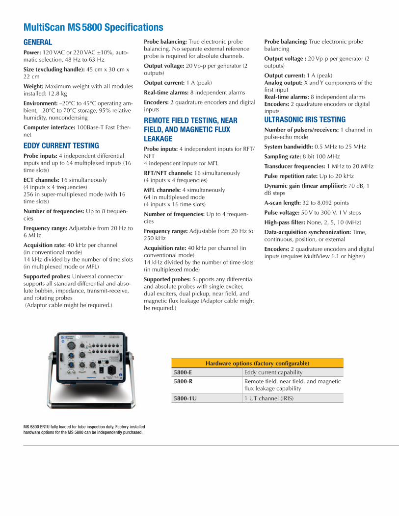
MS 5800 ER1U fully loaded for tube inspection duty. Factory-installed hardware options for the MS 5800 can be independently purchased.
MultiScan MS 5800 SpecificationsGENERALPower: 120 VAC or 220 VAC ±10%, auto-matic selection, 48 Hz to 63 Hz
Size (excluding handle): 45 cm x 30 cm x 22 cm
Weight: Maximum weight with all modules installed: 12.8 kg
Environment: –20°C to 45°C operating am-bient, –20°C to 70°C storage; 95% relative humidity, noncondensing
Computer interface: 100Base-T Fast Ether-net
EDDY CURRENT TESTINGProbe inputs: 4 independent differential inputs and up to 64 multiplexed inputs (16 time slots)
ECT channels: 16 simultaneously (4 inputs x 4 frequencies) 256 in super-multiplexed mode (with 16 time slots)
Number of frequencies: Up to 8 frequen-cies
Frequency range: Adjustable from 20 Hz to 6 MHz
Acquisition rate: 40 kHz per channel (in conventional mode) 14 kHz divided by the number of time slots (in multiplexed mode or MFL)
Supported probes: Universal connector supports all standard differential and abso-lute bobbin, impedance, transmit-receive, and rotating probes (Adaptor cable might be required.)
Probe balancing: True electronic probe balancing. No separate external reference probe is required for absolute channels.
Output voltage: 20 Vp-p per generator (2 outputs)
Output current: 1 A (peak)
Real-time alarms: 8 independent alarms
Encoders: 2 quadrature encoders and digital inputs
REMOTE FIELD TESTING, NEAR FIELD, AND MAGNETIC FLUX LEAKAGEProbe inputs: 4 independent inputs for RFT/NFT 4 independent inputs for MFL
RFT/NFT channels: 16 simultaneously (4 inputs x 4 frequencies)
MFL channels: 4 simultaneously64 in multiplexed mode (4 inputs x 16 time slots)
Number of frequencies: Up to 4 frequen-cies
Frequency range: Adjustable from 20 Hz to 250 kHz
Acquisition rate: 40 kHz per channel (in conventional mode) 14 kHz divided by the number of time slots (in multiplexed mode)
Supported probes: Supports any differential and absolute probes with single exciter, dual exciters, dual pickup, near field, and magnetic flux leakage (Adaptor cable might be required.)
Probe balancing: True electronic probe balancing
Output voltage : 20 Vp-p per generator (2 outputs)
Output current: 1 A (peak)Analog output: X and Y components of the first inputReal-time alarms: 8 independent alarmsEncoders: 2 quadrature encoders or digital inputs
ULTRASONIC IRIS TESTINGNumber of pulsers/receivers: 1 channel in pulse-echo mode
System bandwidth: 0.5 MHz to 25 MHz
Sampling rate: 8 bit 100 MHz
Transducer frequencies: 1 MHz to 20 MHz
Pulse repetition rate: Up to 20 kHz
Dynamic gain (linear amplifier): 70 dB, 1 dB steps
A-scan length: 32 to 8,092 points
Pulse voltage: 50 V to 300 V, 1 V steps
High-pass filter: None, 2, 5, 10 (MHz)
Data-acquisition synchronization: Time, continuous, position, or external
Encoders: 2 quadrature encoders and digital inputs (requires MultiView 6.1 or higher)
Hardware options (factory configurable)
5800-E Eddy current capability
5800-R Remote field, near field, and magnetic flux leakage capability
5800-1U 1 UT channel (IRIS)