28
MSAsafety.com Model Number / Numero de modelo / Numero de modele User Instructions MSA Workman® Tripod Doc./Mat.: 10103973/06 Print Spec.: 10000005389 (F) CR 800000039440
MSAsafety.com
Model Number / Numero de modelo /Numero de modele
User Instructions
MSA Workman® Tripod
Doc./Mat.: 10103973/06Print Spec.: 10000005389 (F)
CR 800000039440
WARNING!National standards and state, provincial and federal laws require the user to be trained before using this product. Use this manual as part of a user safety training program that is appropriate for the user's occupation. These instructions must be provided to users before use of the product and retained for ready reference by the user. The user must read, and understand (or have explained), and heed all instructions, labels, markings and warnings supplied with this product and with those products intended for use in association with it. FAILURE TO DO SO MAY RESULT IN SERIOUS INJURY OR DEATH.
MSA, MSA The Safety Company, and the MSA The Safety Company Logo are Registered Trademarks of MSA Technology, LLC in the U.S. and/or other countries. For all other trade-marks see https://us.msasafety.com/Trademarks
1000 Cranberry Woods DriveCranberry Township, PA 16066USAPhone 1-800-MSA-2222Fax 1-800-967-0398For your local MSA contacts please go to our website www.MSAsafety.com
© MSA 2020. All rights reserved
MSA Workman® Tripod 3
Contents
US
Contents1 Safety Regulations . . . . . . . . . . . . . . . . . . . . . . . . . . . . . . . . . . . . . . . . . . . 41.1 Correct Use . . . . . . . . . . . . . . . . . . . . . . . . . . . . . . . . . . . . . . . . . . . . . . . . . . 41.2 Compliance . . . . . . . . . . . . . . . . . . . . . . . . . . . . . . . . . . . . . . . . . . . . . . . . . . 41.3 Training . . . . . . . . . . . . . . . . . . . . . . . . . . . . . . . . . . . . . . . . . . . . . . . . . . . . . 41.4 Safety and Precautionary Measures to be Adopted . . . . . . . . . . . . . . . . . . . 51.5 Usage Limitations . . . . . . . . . . . . . . . . . . . . . . . . . . . . . . . . . . . . . . . . . . . . . 61.6 Liability Information . . . . . . . . . . . . . . . . . . . . . . . . . . . . . . . . . . . . . . . . . . . . 81.7 Warranty . . . . . . . . . . . . . . . . . . . . . . . . . . . . . . . . . . . . . . . . . . . . . . . . . . . . 8
2 Description . . . . . . . . . . . . . . . . . . . . . . . . . . . . . . . . . . . . . . . . . . . . . . . . . 92.1 System Requirements . . . . . . . . . . . . . . . . . . . . . . . . . . . . . . . . . . . . . . . . . . 92.2 Dimensions . . . . . . . . . . . . . . . . . . . . . . . . . . . . . . . . . . . . . . . . . . . . . . . . . 102.3 Typical Applications . . . . . . . . . . . . . . . . . . . . . . . . . . . . . . . . . . . . . . . . . . 112.4 Heads . . . . . . . . . . . . . . . . . . . . . . . . . . . . . . . . . . . . . . . . . . . . . . . . . . . . . 132.5 Extension Legs . . . . . . . . . . . . . . . . . . . . . . . . . . . . . . . . . . . . . . . . . . . . . . 132.6 Workman Tripod Optional Accessories . . . . . . . . . . . . . . . . . . . . . . . . . . . . 142.7 Markings and Labels . . . . . . . . . . . . . . . . . . . . . . . . . . . . . . . . . . . . . . . . . . 15
3 Use . . . . . . . . . . . . . . . . . . . . . . . . . . . . . . . . . . . . . . . . . . . . . . . . . . . . . . . 163.1 Planning the Use of Systems . . . . . . . . . . . . . . . . . . . . . . . . . . . . . . . . . . . 163.2 Inspection Before Each Use . . . . . . . . . . . . . . . . . . . . . . . . . . . . . . . . . . . . 183.3 Erecting and Compacting Workman Tripod . . . . . . . . . . . . . . . . . . . . . . . . 183.4 Installation Sequence . . . . . . . . . . . . . . . . . . . . . . . . . . . . . . . . . . . . . . . . . 213.5 Making Proper Connections . . . . . . . . . . . . . . . . . . . . . . . . . . . . . . . . . . . . 24
4 Care, Maintenance and Storage . . . . . . . . . . . . . . . . . . . . . . . . . . . . . . . . 244.1 Cleaning Instructions . . . . . . . . . . . . . . . . . . . . . . . . . . . . . . . . . . . . . . . . . . 244.2 Maintenance and Service . . . . . . . . . . . . . . . . . . . . . . . . . . . . . . . . . . . . . . 244.3 Storage . . . . . . . . . . . . . . . . . . . . . . . . . . . . . . . . . . . . . . . . . . . . . . . . . . . . 24
5 Inspection . . . . . . . . . . . . . . . . . . . . . . . . . . . . . . . . . . . . . . . . . . . . . . . . . 255.1 Inspection Frequency . . . . . . . . . . . . . . . . . . . . . . . . . . . . . . . . . . . . . . . . . 255.2 Formal Inspection . . . . . . . . . . . . . . . . . . . . . . . . . . . . . . . . . . . . . . . . . . . . 255.3 Inspection Steps . . . . . . . . . . . . . . . . . . . . . . . . . . . . . . . . . . . . . . . . . . . . . 255.4 Corrective Action . . . . . . . . . . . . . . . . . . . . . . . . . . . . . . . . . . . . . . . . . . . . . 265.5 Inspection Log . . . . . . . . . . . . . . . . . . . . . . . . . . . . . . . . . . . . . . . . . . . . . . . 27
US
MSA Workman® Tripod4
1 Safety Regulations1.1 Correct Use
The Workman Tripod is primarily an anchorage connector component of a personal fall arrest system. It may also be used for work positioning, ladder climbing, rescue, retrieval, evacuation, confined space entry/exit operations and material lifting and lowering, depending on which attachment elements are included.
Use of the Workman Tripod must comply with these User Instructions and, further, is subject to approval under the user’s safety rules and regulations, safety director, supervisor, or a qualified safety engineer. Be certain the selection of the Workman Tripod is suited for the intended use and work envi-ronment. If there is any conflict between these User Instructions and other directives or procedures of the user’s organization, do not use the Workman Tripod until such conflicts are resolved. Consult all local, state, and federal Occupational Health and Safety Administration (OSHA) requirements for personal safety equipment. Also refer to the latest revision of ANSI Z359.18 standard for more infor-mation on anchorages and associated system components. In Canada, refer to provincial and federal regulations and to CSA Z259.10, Z259.11 and Z259.18.
1.2 ComplianceThe product may comply with:
• ANSI Z359.18, Type A; EN795 and / or;
• OSHA requirements
See product label for specific compliance notifications.
Anchorage connectors labeled with ANSI Z359.18 have been tested in compliance with the require-ments of ANSI/ASSE Z359.7.
NOTICE
ANSI compliance and testing covers only the hardware and does not extend to the anchorage and substrate to which the anchorage connector is attached.
1.3 TrainingUsers of MSA Products must be familiar with the User Instructions and be trained by a competent person in:
• workplace hazard identification, evaluation and control
• selection, inspection, use, storage and maintenance
• usage planning including calculation of free and total fall distance; maximum arresting force
• compatibility and selection of anchorage/anchorage connectors including connection to help prevent accidental disengagement (rollout)
• proper lanyard/harness connection locations
• evacuation and rescue planning and implementation
• consequences of improper use
For Confined Space applications:
• See OSHA 29 CFR 1910.146 and ANSI Z117.1.
Periodically (at least annually) assess effectiveness of training and determine the need for retraining or additional training. Contact MSA for training information.
MSA Workman® Tripod 5
US
1.4 Safety and Precautionary Measures to be Adopted
WARNING!
DO NOT exceed the allowable free fall distance or exceed the maximum fall arrest forces as spec-ified by governing standards or subsystem components.
The anchorage to which the MSA Workman Tripod is attached must be rated in the direction of intended use. See sections 2.1.4 "Anchorages and Anchorage Connectors" and 3 "Use" for details on anchorage strength and loading details.
When installing or removing the MSA Workman Tripod limit exposure to fall hazards. A separate independent fall arrest system may be required.
Ensure that fall clearance is sufficient to meet governing standards or subsystem component requirements.
Prevent swing falls and impact with objects in or adjacent to the fall path. Always remove obstruc-tions below the work area to ensure a clear fall path. Keep work area free from debris, obstruc-tions, trip hazards, spills or other hazard which could impair the safe operation of the fall protection system. DO NOT use the MSA Workman Tripod unless a qualified person has inspected the work-place and determined that identified hazards can neither be eliminated nor exposures to them prevented.
Work directly under the anchorage connector at all times. A full body harness is the only accept-able body holding device that can be used in a fall arrest system.
DO NOT rely on feel or sound to verify proper snaphook or carabiner engagement. Ensure that gate and keeper are closed before use.
If the MSA Workman Tripod is damaged or is subjected to fall arrest forces or impact forces, it must be immediately removed from service and marked as "UNUSABLE" until it has been destroyed.
DO NOT leave the MSA Workman Tripod installed in environments which could cause damage or deterioration to the product. Refer to sections 4 "Care, Maintenance and Storage" and 5 "Inspec-tion" for care and inspection details. Do not leave unattended loads on the MSA Workman Tripod.
DO NOT use where lanyard or shock absorber may be exposed to sharp or abrasive edges or sheared, expanded metal, or frame cut steel. Sharp edges may cut a lanyard or shock absorber during a fall. Cover all sharp or abrasive edges with padding or sheathing before working above edge.
Chemical hazards, heat and corrosion may damage the MSA Workman Tripod. More frequent inspections are required in these environments.
DO NOT use the MSA Workman Tripod adjacent to moving machinery, electrical hazards, or in the presence of excessive heat, open flame or molten metal.
DO NOT use fall arrest or rescue equipment in environments with temperatures greater than 130°F (34°C) or temperatures lower than -30°F (-34°C).
DO NOT use the MSA Workman Tripod near energized equipment or where contact with high voltage power lines may occur. The metal components may provide a path for electrical current to flow, resulting in an electrical shock or electrocution.
Remove any surface contamination such as, but not limited to, concrete, stucco, roofing material, etc that could accelerate cutting or abrading of attached components.
MSA Workman Tripods are to be designated and used solely for approved applications.
Unauthorized alterations, relocations, or additions to the anchorage connector extension are not permitted.
DO NOT alter this equipment or intentionally misuse it. DO NOT use fall protection equipment for purposes other than those for which it was designed.
US
MSA Workman® Tripod6
Only one fall protection system is to be attached to the Workman Tripod. Do not attach more than one user or system to the anchorage.
If PPE is resold, it is essential that instructions for use, maintenance, and periodic examination are provided in the language of destination.
DO NOT use MSA Fall Protection products if under the influence of drugs or alcohol.
MSA or persons or entities authorized in writing by the manufacturer, shall make all repairs to the equipment. No unauthorized repairs and/or modifications are permitted.
RESCUE AND EVACUATION: The user must have a rescue plan and the means at hand to imple-ment it. The plan must take into account the equipment and special training necessary to effect prompt rescue under all foreseeable conditions. If the rescue be from a confined space, the provi-sions of OSHA regulation 1910.146 and ANSI Z 117.1 must be taken into account. Although a rescue plan and the means to implement it must always be in place, it is a good idea to provide means for user evacuation without assistance of others. This will usually reduce the time to get to a safe place and reduce or prevent the risk to rescuers.
Failure to follow these warnings can result in serious personal injury or death.
1.5 Usage LimitationsThe following applications limitations must be considered and planned for before using the Workman Tripod.
1.5.1 Physical LimitationsThe Workman Tripod is designed for use by one person with a combined total weight no greater than 400 lbs (182 kg), including clothing, tools, and other user-borne objects; or in lifting or lowering mate-rials with a combined total weight of no greater than 620 lbs (280 kg). Persons with muscular, skeletal, or other physical disorders should consult a physician before using a personal fall arrest system that includes a Workman Tripod. Pregnant women and minors must never use these systems. Increasing age and lowered physical fitness may reduce a person’s ability to withstand shock loads during fall arrest or prolonged suspension. Consult a physician if there is any question about physical ability to safely use this product to arrest a fall or suspend.
1.5.2 HazardsWorkman Tripod must be installed on a clean and dry surface.
Acidic, alkaline, or other environments with harsh substances may damage the hardware elements of this Workman Tripod. If working in a chemically aggressive environment, consult MSA to determine acceptable system components for your specific conditions.
Chemical hazards, heat and corrosion may damage the Workman Tripod. More frequent formal inspec-tions are required in environments with chemical hazards, heat and corrosion. Do not use in environ-ments with temperatures greater than 134°F (34°C). Do not expose to corrosive environments for prolonged periods. Use extreme caution when working near energized electrical sources. Maintain a safe working distance {preferably at least 10 feet (3 m)} from electrical hazards. When working near moving machinery parts (e.g. conveyors, rotating shafts, presses, etc.), make sure that there are no loose elements in any part of the system.
MSA Workman® Tripod 7
US
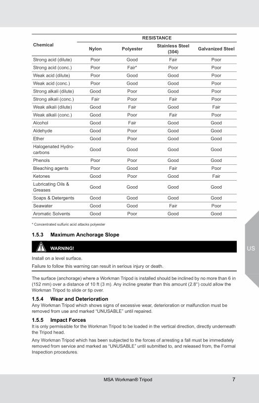
* Concentrated sulfuric acid attacks polyester
1.5.3 Maximum Anchorage Slope
WARNING!
Install on a level surface.
Failure to follow this warning can result in serious injury or death.
The surface (anchorage) where a Workman Tripod is installed should be inclined by no more than 6 in (152 mm) over a distance of 10 ft (3 m). Any incline greater than this amount (2.8°) could allow the Workman Tripod to slide or tip over.
1.5.4 Wear and DeteriorationAny Workman Tripod which shows signs of excessive wear, deterioration or malfunction must be removed from use and marked “UNUSABLE” until repaired.
1.5.5 Impact ForcesIt is only permissible for the Workman Tripod to be loaded in the vertical direction, directly underneath the Tripod head.
Any Workman Tripod which has been subjected to the forces of arresting a fall must be immediately removed from service and marked as “UNUSABLE” until submitted to, and released from, the Formal Inspection procedures.
ChemicalRESISTANCE
Nylon Polyester Stainless Steel (304) Galvanized Steel
Strong acid (dilute) Poor Good Fair Poor
Strong acid (conc.) Poor Fair* Poor Poor
Weak acid (dilute) Poor Good Good Poor
Weak acid (conc.) Poor Good Good Poor
Strong alkali (dilute) Good Poor Good Poor
Strong alkali (conc.) Fair Poor Fair Poor
Weak alkali (dilute) Good Fair Good Fair
Weak alkali (conc.) Good Poor Fair Poor
Alcohol Good Fair Good Good
Aldehyde Good Poor Good Good
Ether Good Poor Good Good
Halogenated Hydro-carbons Good Good Good Good
Phenols Poor Poor Good Good
Bleaching agents Poor Good Fair Poor
Ketones Good Poor Good Fair
Lubricating Oils & Greases Good Good Good Good
Soaps & Detergents Good Good Good Good
Seawater Good Good Fair Poor
Aromatic Solvents Good Poor Good Good
US
MSA Workman® Tripod8
1.5.6 EnvironmentChemical hazards, heat and corrosion may damage the Single Point D-Ring Anchorage Connector. More frequent inspections are required in these environments. Do not use in environments with temperatures greater than 134°F (34°C). Use caution when working around electrical hazards, moving machinery and abrasive surfaces.
1.6 Liability InformationMSA accepts no liability in cases where the device has been used inappropriately or not as intended. The selection and use of the device are the exclusive responsibility of the individual operator.
Product liability claims, warranties and guarantees made by MSA with respect to the device are voided, if it is not used, serviced or maintained in accordance with the instructions in this manual.
1.7 WarrantyExpress Warranty – MSA warrants that the product furnished is free from mechanical defects or faulty workmanship for a period of one (1) year from first use or eighteen (18) months from date of shipment, whichever occurs first, provided it is maintained and used in accordance with MSA’s instructions and/or recommendations. Replacement parts and repairs are warranted for ninety (90) days from the date of repair of the product or sale of the replacement part, whichever occurs first. MSA shall be released from all obligations under this warranty in the event repairs or modifications are made by persons other than its own authorized service personnel or if the warranty claim results from misuse of the product. No agent, employee or representative of MSA may bind MSA to any affirmation, representation or modification of the warranty concerning the goods sold under this contract. MSA makes no warranty concerning components or accessories not manufactured by MSA, but will pass on to the Purchaser all warranties of manufacturers of such components. THIS WARRANTY IS IN LIEU OF ALL OTHER WARRANTIES, EXPRESS, IMPLIED OR STATUTORY, AND IS STRICTLY LIMITED TO THE TERMS HEREOF. MSA SPECIFICALLY DISCLAIMS ANY WARRANTY OF MERCHANTABILITY OR FITNESS FOR A PARTICULAR PURPOSE. Exclusive Remedy - It is expressly agreed that the Purchaser’s sole and exclusive remedy for breach of the above warranty, for any tortious conduct of MSA, or for any other cause of action, shall be the repair and/or replacement, at MSA’s option, of any equipment or parts thereof, that after examination by MSA are proven to be defective. Replacement equipment and/or parts will be provided at no cost to the Purchaser, F.O.B. Purchaser’s named place of destination. Failure of MSA to successfully repair any nonconforming product shall not cause the remedy established hereby to fail of its essential purpose.Exclusion of Consequential Damages Purchaser specifically understands and agrees that under no circumstances will MSA be liable to Purchaser for economic, special, incidental, or consequential damages or losses of any kind whatsoever, including but not limited to, loss of anticipated profits and any other loss caused by reason of the non-operation of the goods. This exclusion is applicable to claims for breach of warranty, tortious conduct or any other cause of action against MSA.For additional information please contact the Customer Service Department at 1-800-MSA-2222 (1-800-672-2222).
MSA Workman® Tripod 9
US
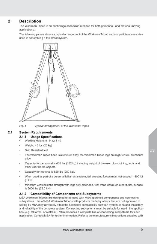
2 DescriptionThe Workman Tripod is an anchorage connector intended for both personnel- and material-moving applications.
The following picture shows a typical arrangement of the Workman Tripod and compatible accessories used in assembling a fall arrest system.
Fig. 1 Typical Arrangement of the Workman Tripod
2.1 System Requirements2.1.1 Usage Specifications• Working Height: 91 in (2.3 m)
• Weight: 45 lbs (20 kg)
• Skid Resistant feet
• The Workman Tripod head is aluminum alloy, the Workman Tripod legs are high-tensile, aluminum alloy.
• Capacity for personnel is 400 lbs (182 kg) including weight of the user plus clothing, tools and other user-borne objects.
• Capacity for material is 620 lbs (280 kg).
• When used as part of a personal fall arrest system, fall arresting forces must not exceed 1,800 lbf (8 kN).
• Minimum vertical static strength with legs fully extended, feet tread-down, on a hard, flat, surface is 5000 lbs (22.0 kN).
2.1.2 Compatibility of Components and SubsystemsMSA Workman Tripods are designed to be used with MSA approved components and connecting subsystems. Use of MSA Workman Tripods with products made by others that are not approved in writing by MSA may adversely affect the functional compatibility between system parts and the safety and reliability of the complete system. Connecting subsystems must be suitable for use in the applica-tion (e.g. fall arrest or restraint). MSA produces a complete line of connecting subsystems for each application. Contact MSA for further information. Refer to the manufacturer’s instructions supplied with
US
MSA Workman® Tripod10
the component or connecting subsystem to determine suitability. For fall arrest applications using the tripod, the maximum fall arrest force must not exceed 1,800 lbf (8 kN).
Contact MSA with any questions regarding compatibility of equipment used with the tripod.
2.1.3 Compatibility of ConnectorsConnectors, such as D-Rings, snaphooks, and carabiners, must be rated at 5,000 lbf (22 kN) minimum breaking strength. MSA connectors meet this requirement. Connecting hardware must be compatible in size, shape, and strength. Non-compatible connectors may accidentally disengage (“rollout”). Always verify compatibility of the connecting snap hook or carabiner with harness D-Ring or anchorage connector. Use only self-closing, self-locking snaphooks and carabiners with the harness.
Use only self-closing, self-locking snaphooks and carabiners to reduce the possibility of rollout. Do not use snaphooks or connectors that will not completely close when attached.
• Do not tie knots in a lanyard.
• Do not connect snaphooks and carabiners to each other.
• Do not connect two (2) snaphooks to one (1) D-ring.
2.1.4 Anchorages and Anchorage ConnectorsPersonal fall arrest system anchorages and connectors must either:
a) have a strength capable of supporting and withstanding at least 5,000 pounds (22.2 kN) in the directions permitted by the system without failure
b) be certified by a professional engineer as having the required strength for fall arrest or travel restraint, as applicable. See ANSI Z359.18 for definition of certification.
When more than one person is attached to an anchor, the minimum anchor strength must be multiplied by the number of personal fall arrest systems attached.
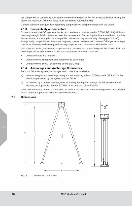
2.2 Dimensions
Fig. 2 Dimension references
MSA Workman® Tripod 11
US
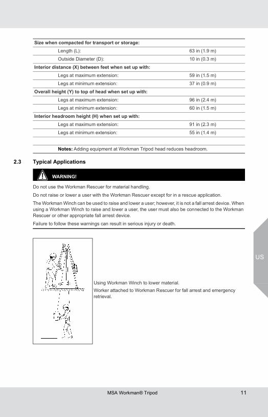
2.3 Typical Applications
WARNING!
Do not use the Workman Rescuer for material handling.
Do not raise or lower a user with the Workman Rescuer except for in a rescue application.
The Workman Winch can be used to raise and lower a user; however, it is not a fall arrest device. When using a Workman Winch to raise and lower a user, the user must also be connected to the Workman Rescuer or other appropriate fall arrest device.
Failure to follow these warnings can result in serious injury or death.
Size when compacted for transport or storage:Length (L): 63 in (1.9 m)
Outside Diameter (D): 10 in (0.3 m)
Interior distance (X) between feet when set up with:Legs at maximum extension: 59 in (1.5 m)
Legs at minimum extension: 37 in (0.9 m)
Overall height (Y) to top of head when set up with:Legs at maximum extension: 96 in (2.4 m)
Legs at minimum extension: 60 in (1.5 m)
Interior headroom height (H) when set up with:Legs at maximum extension: 91 in (2.3 m)
Legs at minimum extension: 55 in (1.4 m)
Notes: Adding equipment at Workman Tripod head reduces headroom.
Using Workman Winch to lower material.Worker attached to Workman Rescuer for fall arrest and emergency retrieval.
US
MSA Workman® Tripod12
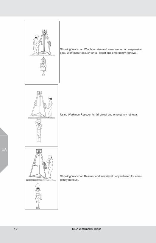
Showing Workman Winch to raise and lower worker on suspension seat. Workman Rescuer for fall arrest and emergency retrieval.
Using Workman Rescuer for fall arrest and emergency retrieval.
Showing Workman Rescuer and Y-retrieval Lanyard used for emer-gency retrieval.
MSA Workman® Tripod 13
US
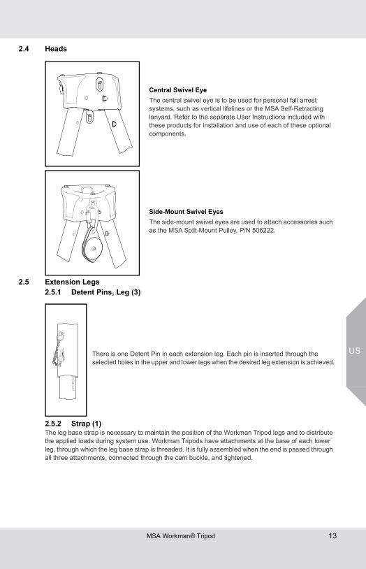
2.4 Heads
2.5 Extension Legs2.5.1 Detent Pins, Leg (3)
2.5.2 Strap (1)The leg base strap is necessary to maintain the position of the Workman Tripod legs and to distribute the applied loads during system use. Workman Tripods have attachments at the base of each lower leg, through which the leg base strap is threaded. It is fully assembled when the end is passed through all three attachments, connected through the cam buckle, and tightened.
Central Swivel EyeThe central swivel eye is to be used for personal fall arrest systems, such as vertical lifelines or the MSA Self-Retracting lanyard. Refer to the separate User Instructions included with these products for installation and use of each of these optional components.
Side-Mount Swivel EyesThe side-mount swivel eyes are used to attach accessories such as the MSA Split-Mount Pulley, P/N 506222.
There is one Detent Pin in each extension leg. Each pin is inserted through the selected holes in the upper and lower legs when the desired leg extension is achieved.
US
MSA Workman® Tripod14
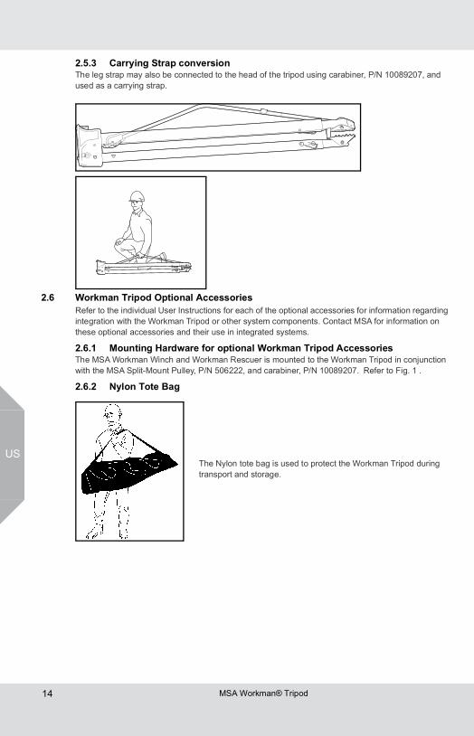
2.5.3 Carrying Strap conversionThe leg strap may also be connected to the head of the tripod using carabiner, P/N 10089207, and used as a carrying strap.
2.6 Workman Tripod Optional AccessoriesRefer to the individual User Instructions for each of the optional accessories for information regarding integration with the Workman Tripod or other system components. Contact MSA for information on these optional accessories and their use in integrated systems.
2.6.1 Mounting Hardware for optional Workman Tripod AccessoriesThe MSA Workman Winch and Workman Rescuer is mounted to the Workman Tripod in conjunction with the MSA Split-Mount Pulley, P/N 506222, and carabiner, P/N 10089207. Refer to Fig. 1 .
2.6.2 Nylon Tote Bag
The Nylon tote bag is used to protect the Workman Tripod during transport and storage.
MSA Workman® Tripod 15
US
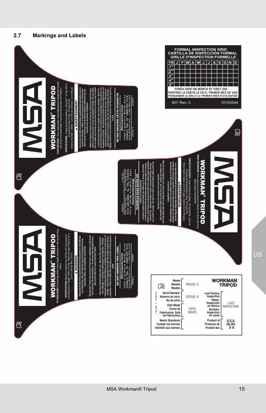
2.7 Markings and Labels
WA
RN
ING
Read
and
stric
tlyfo
llow
sepa
rate
deta
iled
inst
ruct
ions
inUs
erMa
nual.
UseT
ripod
only
with
man
ufac
ture
rapp
rove
deq
uipm
enta
ndas
inst
ruct
ed.M
akeo
nlyc
ompa
tible
conn
ectio
ns.
Rem
ovet
heTr
ipod
from
serv
iceif
itha
sbee
nsu
bjec
ted
toaf
allar
rest
until
itpa
sses
afor
mal
insp
ectio
n.Do
notu
sene
aren
ergi
zed
wire
sth
atco
uld
com
eint
oco
ntac
twith
theT
ripod
.
User
mus
tins
pect
befo
reea
chus
e.Re
mov
efro
mus
eife
xces
sive
wear
,dam
age,
orm
issin
gor
alter
edpa
rtsar
edet
ecte
d.A
form
alin
spec
tion
mus
tbep
erfo
rmed
byac
ompe
tent
pers
onat
least
ever
y12
mon
ths.
Punc
hth
eIns
pect
ion
Grid
afte
rthe
prod
uctp
asse
sfor
mal
insp
ectio
n.Fa
ilure
tofo
llow
this
warn
ing
can
resu
ltin
serio
usin
jury
orde
ath.
TOTA
KEDO
WN:
SPEC
IFIC
ATIO
NS:
Fore
achl
eg,ti
ltthe
tripod
sligh
tly,p
ulldo
wnon
theleg
andh
inge
inwar
d.
Maxim
umwo
rking
load:
400l
bs(1
81kg
)per
sonn
el(in
cludin
gtoo
ls)/W
eight:
43lbs
(19.5
kg);
Maxim
umhe
ight:I
nterio
r:91
in.(2
.3m)
;Ove
rall:
96in.
(2.4
m)
DO
NO
TR
EM
OV
ET
HIS
LAB
EL
WO
RK
MA
NT
RIP
OD
®
Lire
etsu
ivreà
lalet
treles
inst
ruct
ions
supp
lémen
taire
spré
sent
éesd
ansl
em
anue
ldel
'utilis
ateu
r.Ut
iliser
letré
pied
uniq
uem
enta
vecl
'équi
pem
ent
appr
ouvé
parl
efab
rican
tetd
elam
anièr
eind
iqué
e.N'
effe
ctue
rque
des
racc
ords
avec
desp
ièces
com
patib
les.
Retir
erle
trépi
eddu
serv
ices'i
laét
ésou
mis
àdes
forc
esd'a
rrêtd
echu
teju
squ'à
cequ
'ilpa
ssea
vecs
uccè
sune
insp
ectio
nfo
rmell
e.Ne
pasu
tilise
rpr
èsde
câbl
esso
uste
nsio
nqu
ipou
rraien
tent
rere
nco
ntac
tave
clet
répi
ed.
L'util
isate
urdo
itin
spec
terl
epro
duit
avan
tcha
queu
tilisa
tion.
Retir
erdu
serv
iceen
prés
ence
d'usu
reex
cess
ive,d
edom
mag
esou
side
spièc
esso
ntm
anqu
ante
sou
brisé
es.U
nein
spec
tion
form
elled
oitê
treef
fect
uéep
arun
epe
rson
neco
mpé
tent
eau
moi
nsto
usles
douz
e(12
)moi
s.Po
inço
nner
lagr
illed'i
nspe
ctio
nsi
lepr
odui
tasu
biav
ecsu
ccès
l'insp
ectio
nfo
rmell
e.Né
glig
erde
suivr
ecet
aver
tisse
men
tpeu
tent
raîn
erde
sbles
sure
sgra
veso
ula
mor
t.
POUR
DÉPO
SER
:
SPÉC
IFIC
ATIO
NS:Po
urch
aque
patte
,incli
nerlé
gère
ment
letré
pied,
tirerla
patte
vers
leba
setla
déve
rrouil
leren
pous
sant
lach
arniè
reve
rsl'in
térieu
r.
Char
gede
servi
cema
ximum
:per
sonn
el:1
81kg
(400
lb)(in
cluan
tleso
utils)
/Poid
s:19
,5kg
(43l
b);
Haute
urma
ximale
:Intér
ieur:
2,3m
(91p
o);H
ors-t
out:
2,4m
(96p
o)
679001013.ve
R1011
NE
PAS
EN
LEV
ER
CE
TT
EÉ
TIQ
UE
TT
E
WO
RK
MA
NT
RIP
OD
®
AV
ER
TIS
SE
ME
NT
5790
0101
3.ve
R10
11
PARADESARMAR:
ESPECIFICACIONES:
Paracadapata,inclineapenaseltrípode,tiredelapatahaciaabajoydoblehaciaadentro.
Cargamáximadetrabajo:181kg(400lb),personal(incluidaslasherramientas)/Peso:19,5kg(43lb);
Alturamáxima:Interior:2,3m(91pulg.);General:2,4m
(96pulg.)
LeaysigadetenidamentelasinstruccionesdetalladasdelManualdel
usuarioquevienen
porseparado.Useeltrípodesolamentecon
equiposaprobadosporelfabricante ysegún
l asinstrucciones .Solamentehaga
conexionescompatibles.
Dejedeusarelt rípodesif ueusadoparadetenerunacaídahastaquepase
unainspecciónform
al.Nolo
usecercadecablesenergizadosquepodrían
entrarencontact o
coneltrípode.
Elusuariodebeinspeccionarlo
antesdecadauso.Dejedeusarlosise
detectandesgasteexcesivo,dañoso
piezasalteradas.Unapersonacom
petentedeberealizarunainspecciónform
alalmenoscada12m
eses.Perforelacartillad einspección
despuésdequeelproductopasela
inspecciónform
al.Elnoseguirestaadvertencia podríaocasionar
lesionesgravesolam
uerte.
NO
QU
ITE
ES
TAE
TIQ
UE
TA
AD
VE
RT
EN
CIA
WO
RK
MA
NT
RIP
OD
®
Serial NumberNúmero de serie
No de série
Date Made
Datede Fabrication
Fecha deFabricacion
Meets StandardsCumple las normas
Satisfait aux normes
Product ofProducto deProduit des
011R
1ve
3.01750101
Last FactoryInspection
Últimainspecciónen fábricaDernière
inspectionen usine
U.S.A.EE.UU.É-U
ModelModeloModèle
SERIAL #
DATEMADE
LASTINSPECTION
MODEL #WORKMAN
TRIPOD®
US
MSA Workman® Tripod16
3 Use3.1 Planning the Use of Systems
3.1.1 Rescue and EvacuationThe user must have a rescue plan and the means at hand to implement it. The plan must take into account the equipment and special training necessary to effect prompt rescue under all foreseeable conditions. If the rescue is from a confined space, the provisions of OSHA regulation 1910.146 and ANSI Z117.1 must be taken into account. Although a rescue plan and the means to implement it must always be in place, it is a good idea to provide means for user evacuation without assistance of others. This will usually reduce the time to get to a safe place and reduce or prevent the risk to rescuers. If the Workman Tripod is to be included as part of rescue or evacuation systems, the optional system compo-nents required, the time required to erect the Workman Tripod and attach any optional components, and the anchorage requirements should be considered when planning these systems.
3.1.2 Free Fall DistanceDo not exceed free fall distance specified by applicable regulations and standards. When using a shock absorbing lanyard, keep the amount of slack between the anchorage/anchorage connector and the harness/waist belt at a minimum to reduce the free fall distance and the impact force to the user.
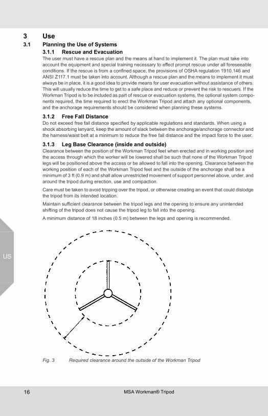
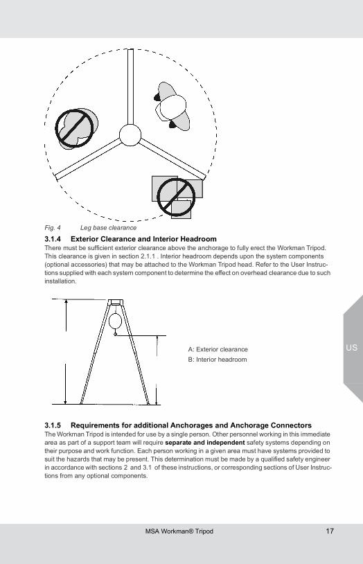
3.1.3 Leg Base Clearance (inside and outside)Clearance between the position of the Workman Tripod feet when erected and in working position and the access through which the worker will be lowered shall be such that none of the Workman Tripod legs will be positioned above the access or be allowed to fall into the opening. Clearance between the working position of each of the Workman Tripod feet and the outside of the anchorage shall be a minimum of 3 ft (0.9 m) and shall allow unrestricted movement of support personnel above, under, and around the tripod during erection, use and compaction.
Care must be taken to avoid tripping over the tripod, or otherwise creating an event that could dislodge the tripod from its intended location.
Maintain sufficient clearance between the tripod legs and the opening to ensure any unintended shifting of the tripod does not cause the tripod leg to fall into the opening.
A minimum distance of 18 inches (0.5 m) between the legs and opening is recommended.
Fig. 3 Required clearance around the outside of the Workman Tripod
MSA Workman® Tripod 17
US
3.1.4 Exterior Clearance and Interior HeadroomThere must be sufficient exterior clearance above the anchorage to fully erect the Workman Tripod. This clearance is given in section 2.1.1 . Interior headroom depends upon the system components (optional accessories) that may be attached to the Workman Tripod head. Refer to the User Instruc-tions supplied with each system component to determine the effect on overhead clearance due to such installation.
3.1.5 Requirements for additional Anchorages and Anchorage ConnectorsThe Workman Tripod is intended for use by a single person. Other personnel working in this immediate area as part of a support team will require separate and independent safety systems depending on their purpose and work function. Each person working in a given area must have systems provided to suit the hazards that may be present. This determination must be made by a qualified safety engineer in accordance with sections 2 and 3.1 of these instructions, or corresponding sections of User Instruc-tions from any optional components.
Fig. 4 Leg base clearance
A: Exterior clearanceB: Interior headroom
US
MSA Workman® Tripod18
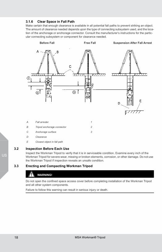
3.1.6 Clear Space in Fall PathMake certain that enough clearance is available in all potential fall paths to prevent striking an object. The amount of clearance needed depends upon the type of connecting subsystem used, and the loca-tion of the anchorage or anchorage connector. Consult the manufacturer’s instructions for the partic-ular connecting subsystem or component for clearance needed.
3.2 Inspection Before Each UseInspect the Workman Tripod to verify that it is in serviceable condition. Examine every inch of the Workman Tripod for severe wear, missing or broken elements, corrosion, or other damage. Do not use the Workman Tripod if inspection reveals an unsafe condition.
3.3 Erecting and Compacting Workman Tripod
WARNING!
Do not open the confined space access cover before completing installation of the Workman Tripod and all other system components.
Failure to follow this warning can result in serious injury or death.
Before Fall Free Fall Suspension After Fall Arrest
A Fall arrester 1
B Tripod anchorage connector 2
C Anchorage surface 3
D Clearance
E Closest object in fall path
MSA Workman® Tripod 19
US
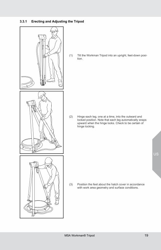
3.3.1 Erecting and Adjusting the Tripod
(1) Tilt the Workman Tripod into an upright, feet-down posi-tion.
(2) Hinge each leg, one at a time, into the outward and locked position. Note that each leg automatically snaps upward when the hinge locks. Check to be certain of hinge locking.
(3) Position the feet about the hatch cover in accordance with work area geometry and surface conditions.
US
MSA Workman® Tripod20
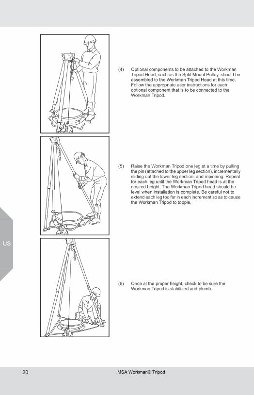
(4) Optional components to be attached to the Workman Tripod Head, such as the Split-Mount Pulley, should be assembled to the Workman Tripod Head at this time. Follow the appropriate user instructions for each optional component that is to be connected to the Workman Tripod.
(5) Raise the Workman Tripod one leg at a time by pulling the pin (attached to the upper leg section), incrementally sliding out the lower leg section, and repinning. Repeat for each leg until the Workman Tripod head is at the desired height. The Workman Tripod head should be level when installation is complete. Be careful not to extend each leg too far in each increment so as to cause the Workman Tripod to topple.
(6) Once at the proper height, check to be sure the Workman Tripod is stabilized and plumb.
MSA Workman® Tripod 21
US
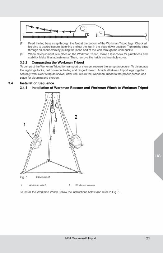
(7) Feed the leg base strap through the feet at the bottom of the Workman Tripod legs. Check all leg pins to assure secure fastening and set the feet in the tread-down position. Tighten the strap through all connectors by pulling the loose end of the web through the cam buckle
(8) When all equipment is in place on the Workman Tripod, make a last check for plumbness and stability. Make final adjustments. Then, remove the hatch and manhole cover.
3.3.2 Compacting the Workman TripodTo compact the Workman Tripod for transport or storage, reverse the setup procedure. To disengage the leg hinge locks, pull down on the leg and hinge it inward. Attach Workman Tripod legs together securely with lower strap as shown. After use, return the Workman Tripod to the proper person and place for cleaning and storage.
3.4 Installation Sequence3.4.1 Installation of Workman Rescuer and Workman Winch to Workman Tripod
Fig. 5 Placement
To install the Workman Winch, follow the instructions below and refer to Fig. 8 .
1 Workman winch 2 Workman rescuer
12
US
MSA Workman® Tripod22
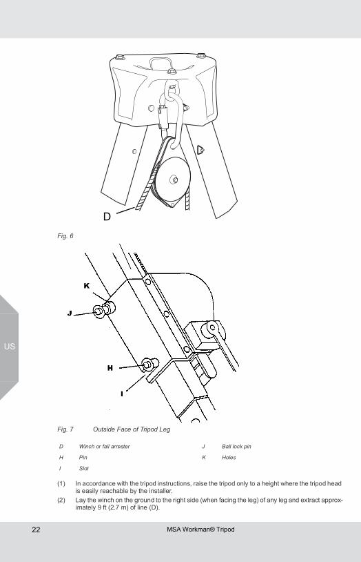
(1) In accordance with the tripod instructions, raise the tripod only to a height where the tripod head is easily reachable by the installer.
(2) Lay the winch on the ground to the right side (when facing the leg) of any leg and extract approx-imately 9 ft (2.7 m) of line (D).
Fig. 6
Fig. 7 Outside Face of Tripod Leg
D Winch or fall arrester J Ball lock pin
H Pin K Holes
I Slot
D
MSA Workman® Tripod 23
US
(3) Reeve the cable over the split-mount pulley and, using carabiner, PN 10089207, mount the pulley to the tripod head to the RIGHT of the leg to which the winch is to be mounted. Note: The winch snaphook must hang to the interior of the tripod.
(4) If using a leg-mounted fall arrester, such as the Workman Rescuer, lay the fall arrester to the right of any other tripod leg and extract enough line to reeve the cable over a split-mount pulley and attach to the tripod head to the right of the leg to which the fall arrester is to be mounted.
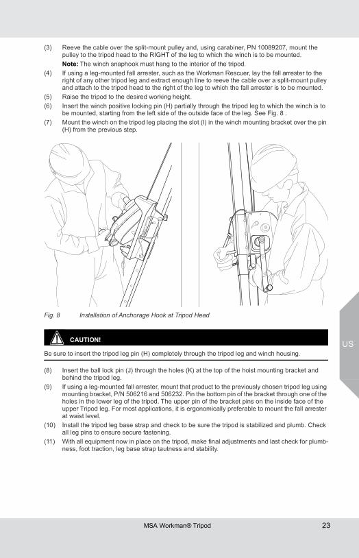
(5) Raise the tripod to the desired working height.(6) Insert the winch positive locking pin (H) partially through the tripod leg to which the winch is to
be mounted, starting from the left side of the outside face of the leg. See Fig. 8 .(7) Mount the winch on the tripod leg placing the slot (I) in the winch mounting bracket over the pin
(H) from the previous step.
Fig. 8 Installation of Anchorage Hook at Tripod Head
CAUTION!
Be sure to insert the tripod leg pin (H) completely through the tripod leg and winch housing.
(8) Insert the ball lock pin (J) through the holes (K) at the top of the hoist mounting bracket and behind the tripod leg.
(9) If using a leg-mounted fall arrester, mount that product to the previously chosen tripod leg using mounting bracket, P/N 506216 and 506232. Pin the bottom pin of the bracket through one of the holes in the lower leg of the tripod. The upper pin of the bracket pins on the inside face of the upper Tripod leg. For most applications, it is ergonomically preferable to mount the fall arrester at waist level.
(10) Install the tripod leg base strap and check to be sure the tripod is stabilized and plumb. Check all leg pins to ensure secure fastening.
(11) With all equipment now in place on the tripod, make final adjustments and last check for plumb-ness, foot traction, leg base strap tautness and stability.
US
MSA Workman® Tripod24
3.5 Making Proper Connections3.5.1 Use of Head AttachmentsCarabiner, P/N 10089207, is used to mount the optional MSA Split-Mount Pulley P/N 506222 to the side attachment points on the Workman Tripod Head. The Split-Mount Pulley is designed to work in conjunction with a Workman Rescuer or Workman Winch, where the cable of the Workman Rescuer or Hoist would pass through the Side-Mount Pulley and descend into the center of the work access. The optional Lynx Boom Hoist may be attached to the central attachment point on the Workman Tripod Head. Contact MSA for information about connection of optional components to the Workman Tripod or refer to the separate User Instructions provided with each component.
3.5.2 Making ConnectionsWhen using a snaphook to connect to an anchorage or when coupling components of the system together, be certain accidental disengagement (“rollout”) cannot occur. Rollout is possible when inter-ference between a snaphook and the mating connector causes the snaphook’s gate or keeper to acci-dentally open and release. Rollout occurs when a snaphook is snapped into an undersized ring such as an eye bolt or other non-compatibly shaped connector. Only self- closing, self-locking snaphooks and carabiners should be used to reduce the possibility of rollout when making connections. Do not use snaphooks or connectors that will not completely close over the attachment object. Do not make knots in a lanyard. Do not hook the lanyard back onto itself. Snaphooks and carabiners must not be connected to each other. Do not attach two snaphooks into one D-ring. Always follow the manufac-turer’s instructions supplied with each system component.
4 Care, Maintenance and Storage4.1 Cleaning Instructions
Clean the Workman Tripod with a solution of water and mild laundry detergent. Dry hardware with a clean cloth. Do not speed drying with heat. Excessive accumulation of dirt, paint, or other foreign matter may prevent proper function of the Workman Tripod and, in severe cases, weaken the material and joints. Questions concerning Workman Tripod conditions and cleaning should be directed to MSA.
4.2 Maintenance and ServiceEquipment which is damaged or in need of maintenance must be tagged as “UNUSABLE” and removed from service. Corrective maintenance (other than cleaning) and repair, such as replacement of elements, must be performed by the MSA factory. Do not attempt field repairs.
4.3 StorageStore the Workman Tripod in a cool, dry and clean place. Avoid areas where heat, moisture, oil, and chemicals or their vapors or other degrading elements may be present. Equipment which is damaged or in need of maintenance should not be stored in the same area as usable equipment. Heavily soiled, wet, or otherwise contaminated equipment should be properly maintained (e.g. dried and cleaned) prior to storage. Prior to using equipment which has been stored for long periods of time, a Formal Inspection should be performed by a competent person.
MSA Workman® Tripod 25
US
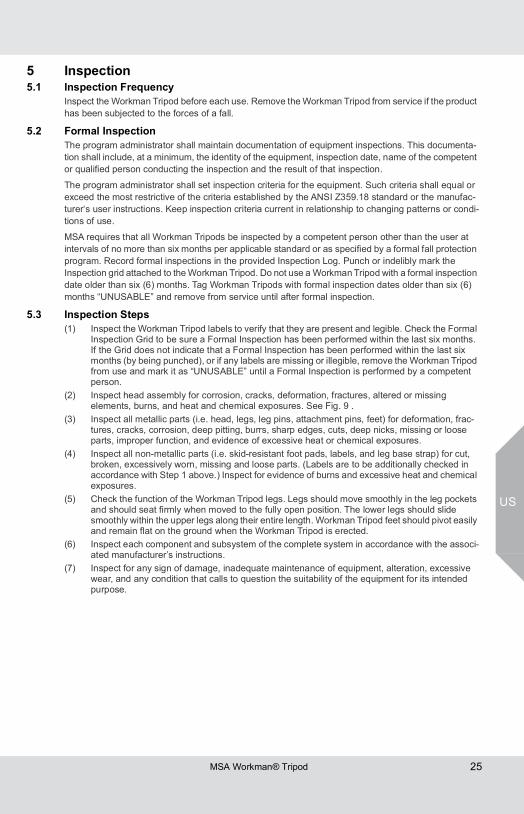
5 Inspection5.1 Inspection Frequency
Inspect the Workman Tripod before each use. Remove the Workman Tripod from service if the product has been subjected to the forces of a fall.
5.2 Formal InspectionThe program administrator shall maintain documentation of equipment inspections. This documenta-tion shall include, at a minimum, the identity of the equipment, inspection date, name of the competent or qualified person conducting the inspection and the result of that inspection.
The program administrator shall set inspection criteria for the equipment. Such criteria shall equal or exceed the most restrictive of the criteria established by the ANSI Z359.18 standard or the manufac-turer‘s user instructions. Keep inspection criteria current in relationship to changing patterns or condi-tions of use.
MSA requires that all Workman Tripods be inspected by a competent person other than the user at intervals of no more than six months per applicable standard or as specified by a formal fall protection program. Record formal inspections in the provided Inspection Log. Punch or indelibly mark the Inspection grid attached to the Workman Tripod. Do not use a Workman Tripod with a formal inspection date older than six (6) months. Tag Workman Tripods with formal inspection dates older than six (6) months “UNUSABLE” and remove from service until after formal inspection.
5.3 Inspection Steps(1) Inspect the Workman Tripod labels to verify that they are present and legible. Check the Formal
Inspection Grid to be sure a Formal Inspection has been performed within the last six months. If the Grid does not indicate that a Formal Inspection has been performed within the last six months (by being punched), or if any labels are missing or illegible, remove the Workman Tripod from use and mark it as “UNUSABLE” until a Formal Inspection is performed by a competent person.
(2) Inspect head assembly for corrosion, cracks, deformation, fractures, altered or missing elements, burns, and heat and chemical exposures. See Fig. 9 .
(3) Inspect all metallic parts (i.e. head, legs, leg pins, attachment pins, feet) for deformation, frac-tures, cracks, corrosion, deep pitting, burrs, sharp edges, cuts, deep nicks, missing or loose parts, improper function, and evidence of excessive heat or chemical exposures.
(4) Inspect all non-metallic parts (i.e. skid-resistant foot pads, labels, and leg base strap) for cut, broken, excessively worn, missing and loose parts. (Labels are to be additionally checked in accordance with Step 1 above.) Inspect for evidence of burns and excessive heat and chemical exposures.
(5) Check the function of the Workman Tripod legs. Legs should move smoothly in the leg pockets and should seat firmly when moved to the fully open position. The lower legs should slide smoothly within the upper legs along their entire length. Workman Tripod feet should pivot easily and remain flat on the ground when the Workman Tripod is erected.
(6) Inspect each component and subsystem of the complete system in accordance with the associ-ated manufacturer’s instructions.
(7) Inspect for any sign of damage, inadequate maintenance of equipment, alteration, excessive wear, and any condition that calls to question the suitability of the equipment for its intended purpose.
US
MSA Workman® Tripod26
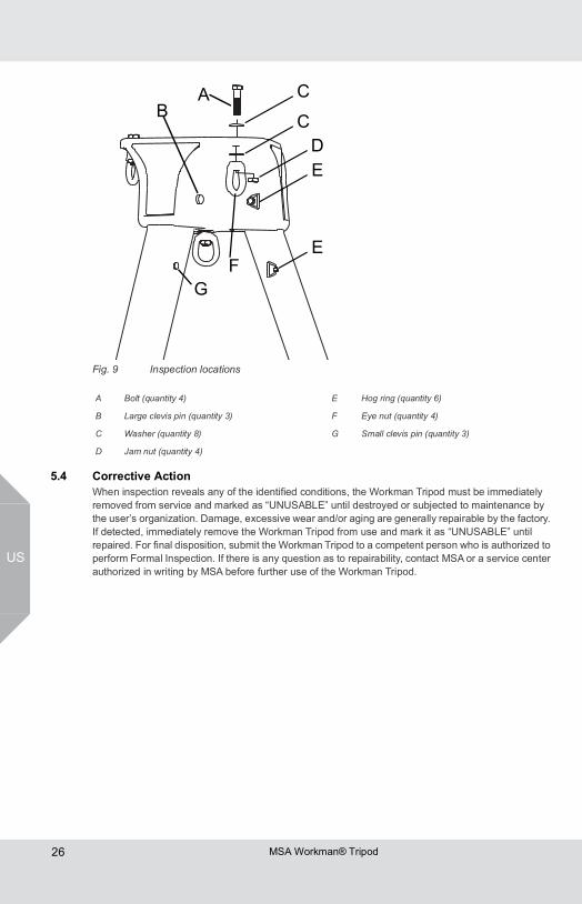
Fig. 9 Inspection locations
5.4 Corrective ActionWhen inspection reveals any of the identified conditions, the Workman Tripod must be immediately removed from service and marked as “UNUSABLE” until destroyed or subjected to maintenance by the user’s organization. Damage, excessive wear and/or aging are generally repairable by the factory. If detected, immediately remove the Workman Tripod from use and mark it as “UNUSABLE” until repaired. For final disposition, submit the Workman Tripod to a competent person who is authorized to perform Formal Inspection. If there is any question as to repairability, contact MSA or a service center authorized in writing by MSA before further use of the Workman Tripod.
A Bolt (quantity 4) E Hog ring (quantity 6)
B Large clevis pin (quantity 3) F Eye nut (quantity 4)
C Washer (quantity 8) G Small clevis pin (quantity 3)
D Jam nut (quantity 4)
AB C
C
DE
EF
G
MSA Workman® Tripod 27
US
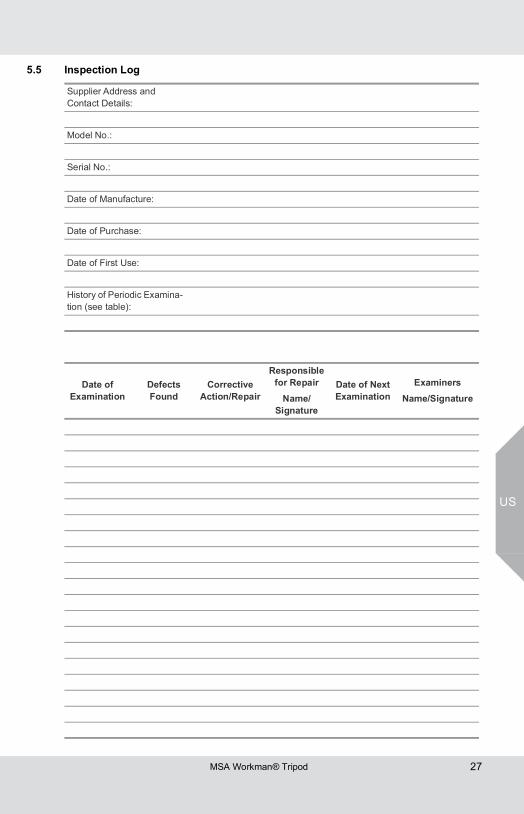
5.5 Inspection Log
Supplier Address and Contact Details:
Model No.:
Serial No.:
Date of Manufacture:
Date of Purchase:
Date of First Use:
History of Periodic Examina-tion (see table):
Date of Examination
Defects Found
Corrective Action/Repair
Responsible for Repair
Name/Signature
Date of NextExamination
ExaminersName/Signature

For local MSA contacts, please visit us at MSAsafety.com


