32
SEAL Basin Fractured Basement Challenging the Exploration Paradigm February, 1 st , 2012
| Date post: | 14-Apr-2017 |
| Category: |
Documents |
| Upload: | sergio-esperancinha |
| View: | 51 times |
| Download: | 6 times |
SEAL Basin Fractured Basement
Challenging the Exploration Paradigm
February, 1st, 2012

SEAL Basin Fractured Basement – Challenging the Exploration Paradigm2
Index
Basin presentation
Naturally Fractured Reservoirs Exploration Workflow
1
3
How it works
Fracture System Identification and Properties
3.1
3.2
2 Assessment of the Problem and Objectives
Technical Recommendations4
Volumes Calculations3.2
Final Considerations5
1. Basin Presentation

SEAL Basin Fractured Basement – Challenging the Exploration Paradigm4
1. Basin Presentation
A narrow band of about 35 km wide, stretching for about 350 km in the NE-SW direction.
Area= 45,960 km2, Emerged Area= 13.200 km2
Formed during the opening of the SouthAtlantic in the late Jurassic and Cretaceous.
Late Aptian
2. Assessment of the Problem and Objectives

SEAL Basin Fractured Basement – Challenging the Exploration Paradigm6
2. Assessment of the Problem and Objectives
In 2005 GALP acquired a set of exploration blocks located in Sergipe-Alagoas Basin
Phase I: Four exploratory wells (Alpha, Beta, Charlie and Delta)
Objective: Ibura Member carbonates
First well demonstrated the potential of the fractured Basement play
Phase II: Three exploratory wells (Echo, Fox and Golf)
Confirmed the results of the previous campaign
Fractured metamorphic basement rock presented the best results in the cuttings and when Drill Stem Tested.
By the time of fourth well it had become the primary objective
Proved the presence of a Naturally Fractured Reservoir (NFR) in the Basement rock
SEAL Basin Fractured Basement – Challenging the Exploration Paradigm7
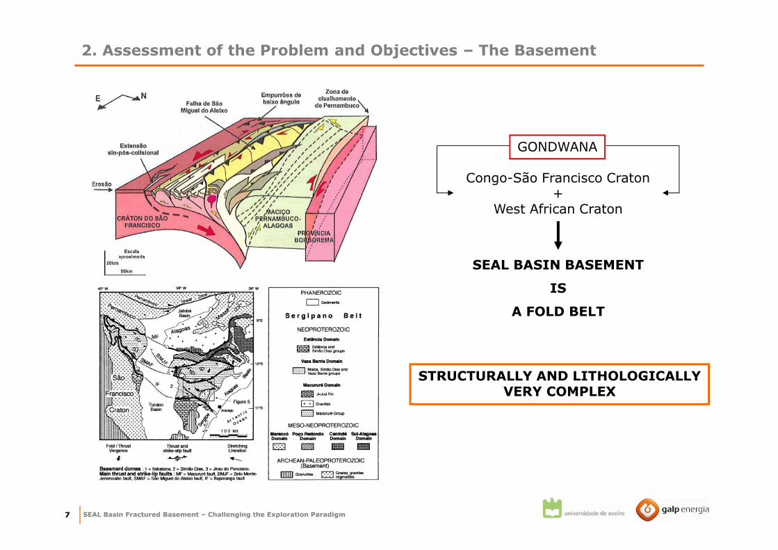
GONDWANA
Congo-São Francisco Craton +
West African Craton
SEAL BASIN BASEMENT
IS
A FOLD BELT
STRUCTURALLY AND LITHOLOGICALLY VERY COMPLEX
2. Assessment of the Problem and Objectives – The Basement

SEAL Basin Fractured Basement – Challenging the Exploration Paradigm8
2. Assessment of the Problem and Objectives – The Basement
Conditions for HC accumulation in Basement rock
3. Migration: laterally from sources to
fractured, topographically higher, basement
rock.
2. Source:
a) Overlying organic rock from which oil
is expelled downward during
compaction.
b) Lateral, off-the-basement, but
topographically lower, organic rock.
c) Lower, lateral reservoirs from which
earlier trapped oil is spilled.
4. Reservoir: fractured basement rock.
SEAL Fractured Basement Play
Maceió Fm. black shales, with typeII Organic Matter (OM) andaverage Total Organic Carbon(TOC) content of 3.5%.
Ibura Member anhydrite1. Seal: as in any other reservoir a
impermeable cap rock is necessary to retain
HC.
Through normal faults to theCarmópolis Mb. sandstones, andthen laterally to structural highs
Fractured basement rock.

SEAL Basin Fractured Basement – Challenging the Exploration Paradigm9
Echo Alpha Fox Bravo
Riachuelo Fm.
Ibura Mb.
Basement
Cotinguiba Fm.
Calumbi Fm.
2. Assessment of the Problem and Objectives – Schematic Seismic Section

SEAL Basin Fractured Basement – Challenging the Exploration Paradigm10
2. Assessment of the Problem and Objectives
Complex Reservoir
Hard rock of low porosity and permeability
Fractures provide main flow path
Joint team
Universidade de Aveiro
Universidade Nova de Lisboa
Universidade do Algarve
Instituto Superior Técnico
THESIS
Integrated all the data and results
of the project
+
Analysis of the drilling and testing
procedures
FINAL OBJECTIVE
Provide technical recommendation
on how future exploration
campaigns should be run.
Discrete Fracture Network and simulate 3D permeability maps.
Structurally Characterize Basement Rock
Naturally Fractured Reservoirs Exploration Workflow
3. Naturally Fractured Reservoirs Exploration Workflow

SEAL Basin Fractured Basement – Challenging the Exploration Paradigm12
Assess if the reservoir is fractured
NO
Seismic Acquisition
+Processing
Geomechanical Models
DFN Models
constrain
Volumetrics Well Design
YES?
Identify the Fracture System
Well data
Outcrop data
Regional geology
Seismic
AVAILABLE?
3. NFR Exploration Workflow – How it Works?
Fracture Properties Affecting Reservoir Performance
•Morphology
•Width/Permeability
•Spacing
+Fracture-Matrix interaction
derive
information
Lithology
Distribution of fracture patterns
Rock mechanical properties
YES
Seismic Interpretation
Fracture System Origin information
SEAL Basin Fractured Basement – Challenging the Exploration Paradigm13
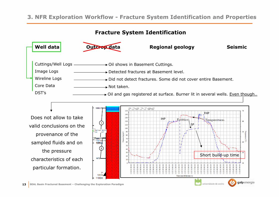
3. NFR Exploration Workflow - Fracture System Identification and Properties
Well data Outcrop data Regional geology Seismic
Fracture System Identification
Cuttings/Well Logs
Image Logs
Wireline Logs
Core Data
DST’s
Oil shows in Basement Cuttings.
Detected fractures at Basement level.
Did not detect fractures. Some did not cover entire Basement.
Not taken.
Erroneous procedures:
→ different wells tested
different stratigraphic
sections
→ standard procedures
were not followed
Does not allow to take
valid conclusions on the
provenance of the
sampled fluids and on
the pressure
characteristics of each
particular formation.
Oil and gas registered at surface. Burner lit in several wells. Even though..
Short build-up time
SP
IHP
FHP

SEAL Basin Fractured Basement – Challenging the Exploration Paradigm14
3. NFR Exploration Workflow - Fracture System Identification and Properties
Well data Outcrop data Regional geology Seismic
Fracture System Identification
Stress Direction
NS normal
E-W/ENE-WSW transfer faults
NW-SW normal
NNW-SSE transfer faults
Chagas
Faulting
E-W
NW-SE
Fracture System Origin
Faults and fractures were
considered to be formed by
tectonic stress, as a consequence
of both the collision during Pre-
Cambrian times, and the opening
of Atlantic Ocean.
Bad quality seismic was available
Horizons and faults were interpreted
+
Attributes were extracted
(Coherence + Dip Az.+ Dip Mag.)
+
U.Aveiro: new Methodology for Automatic
fault detection + seismic enhancement

SEAL Basin Fractured Basement – Challenging the Exploration Paradigm15
More faults could be interpreted!
3. NFR Exploration Workflow - Fracture System Identification and Properties
SEAL Basin Fractured Basement – Challenging the Exploration Paradigm16
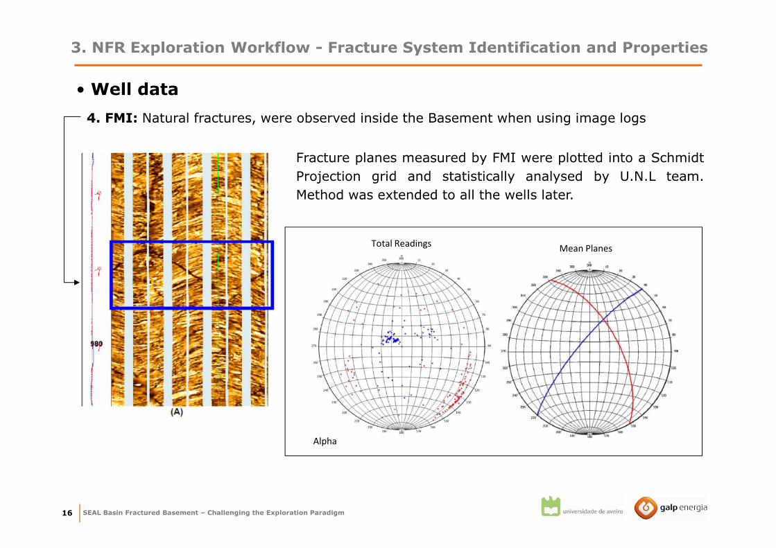
• Well data
3. NFR Exploration Workflow - Fracture System Identification and Properties
4. FMI: Natural fractures, were observed inside the Basement when using image logs
Fracture planes measured by FMI were plotted into a Schmidt
Projection grid and statistically analysed by U.N.L team.
Method was extended to all the wells later.
Total ReadingsMean Planes
Alpha

SEAL Basin Fractured Basement – Challenging the Exploration Paradigm17
Alpha Beta Delta Fox Golf
Alpha-2 Beta-1 Delta-2A Fox-1A Golf-1A A 104 N22ºW/60ºNE N30ºW/57ºNE
Alpha-1 Beta-2B - - - B2 16 N38ºE/63ºNW N43ºE/79ºNW
- Beta-2A - Fox-2 - B1 7 N30ºE/42ºSE N30ºE/35ºSE
- - Delta-1 - - - - - -
Delta-2B Fox-1B - D 28 N8ºE/56ºNW -
- - Delta-3 - Golf-2 E 25 N87ºE/35ºSE -
- - - - Golf-1B - - N20ºW/39ºSW -
General Trend
(U.N.L)
Correspondence of Fracture Families Per wellFinal
General Trend
(GALP)
Measurements
in Basement
Family A is the most common,
being present in every well with a
total of 104 measurements inside
the Basement.
Future Well should intersect Family A!
Five fracture families were found.
3. NFR Exploration Workflow - Fracture System Identification and Properties

SEAL Basin Fractured Basement – Challenging the Exploration Paradigm18
3. NFR Exploration Workflow - Fracture System Identification and Properties
Properties of the Fracture System
Morphology Spacing Width/Permeabilty
Geomechanical Modelling (UALG): simulated the
density and orientation of fractures in the space
between the wells (the whole reservoir space).
Output
Mohr-Coulomb Shear Stress values and the predicted
conjugated fractures shear strikes and dips
By combining the Mohr-Coulomb Theory, with the
Anderson’s principles and the frictional fault theory,
regional tectonic stresses were simulated over the grid
with embedded faults

SEAL Basin Fractured Basement – Challenging the Exploration Paradigm19
Properties of the Fracture System
Morphology Spacing Width/Permeabilty
3. NFR Exploration Workflow - Fracture System Identification and Properties
DFN/Φ and K Modelling (UNL): Generated equivalent permeability histograms of each FMI
fracture family by using data from the FMI statistical analysis and the geomechanical
modelling.
1. The number of fractures by family and
correspondent distribution of areas that match
a specific Linear Fracture Density at vertical
direction (FMI direction) were estimated.
FTRIAN software:
a) Monte Carlo algorithm generates fracture
networks using a polygonal approximation
(squares).
b) Sampled with scan lines simulating a well.
…to do this…

SEAL Basin Fractured Basement – Challenging the Exploration Paradigm20
#1 #2 #3
5000 0.072 0.079 0.064 0.072
10000 0.149 0.156 0.147 0.151
15000 0.214 0.211 0.214 0.213
20000 0.276 0.302 0.297 0.292
25000 0.360 0.366 0.369 0.365
30000 0.431 0.426 0.438 0.432
35000 0.531 0.514 0.522 0.522
40000 0.597 0.589 0.601 0.596
45000 0.657 0.633 0.695 0.662
50000 0.733 0.719 0.736 0.730
55000 0.793 0.817 0.804 0.805
60000 0.857 0.891 0.876 0.875
65000 0.966 0.974 0.961 0.967
70000 1.019 1.027 1.032 1.026
75000 1.115 1.111 1.088 1.104
80000 1.132 1.153 1.196 1.161
85000 1.222 1.264 1.230 1.239
90000 1.308 1.337 1.350 1.332
95000 1.370 1.403 1.420 1.397
100000 1.452 1.467 1.464 1.461
105000 1.485 1.557 1.527 1.523
110000 1.592 1.622 1.613 1.609
115000 1.645 1.705 1.679 1.677
120000 1.739 1.812 1.763 1.772
125000 1.788 1.870 1.832 1.830
130000 1.909 1.962 1.881 1.917
135000 1.971 2.019 1.959 1.983
140000 2.075 2.060 2.078 2.071
145000 2.132 2.149 2.133 2.138
150000 2.173 2.215 2.206 2.198
155000 2.287 2.293 2.297 2.292
160000 2.313 2.346 2.333 2.331
165000 2.405 2.439 2.472 2.439
170000 2.464 2.522 2.491 2.493
175000 2.562 2.583 2.583 2.576
Family A
Low
Intermediate
High
N Average LFD LFD classRealisations
3. NFR Exploration Workflow - Fracture System Identification and Properties
This reads…
It is necessary to generate approximately175000 fractures of family A to reach a LFD indexof 2.6 (maximum observed).
Using the values from the table it was possible to
estimate permeability and porosity for each of
the fracture families using the Oda method.
0
0.2
0.4
0.6
0.8
1
1.2
0 50 100 150 200 250 300 350 400 450
Fre
qu
en
cy
Permeability (Darcys)
Max equivalent permeability - T-412-429
Family A Family B1 Family B2
Block-A Max Equivalent Permeability
Interval Average Interval AverageA [0; 381.524] 171.526 [0; 0.0046] 0.0021
B1 [0; 238.733] 93.131 [0; 0.0029] 0.0011
B2 [0; 163.818] 60.454 [0; 0.0019] 0.00072A [0; 350.346] 147.504 [0; 0.0049] 0.0021
B1 [0; 221.449] 91.235 [0; 0.0026] 0.0011
B2 [0; 145.246] 57.182 [0; 0.0017] 0.00068
A
B
BlockFracture family
Permeability (Darcys) Porosity (%)
Values can now be used of Volumes calculations
SEAL Basin Fractured Basement – Challenging the Exploration Paradigm21
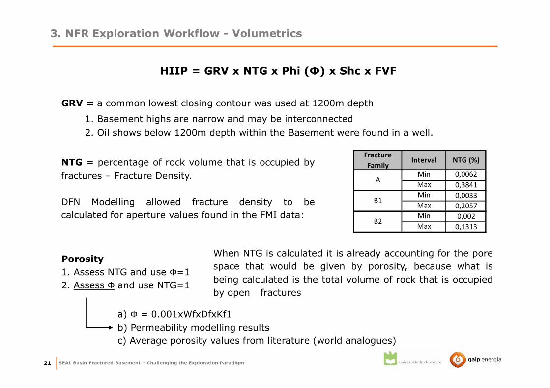
3. NFR Exploration Workflow - Volumetrics
HIIP = GRV x NTG x Phi (Φ) x Shc x FVF
GRV = a common lowest closing contour was used at 1200m depth
1. Basement highs are narrow and may be interconnected
2. Oil shows below 1200m depth within the Basement were found in a well.
NTG = percentage of rock volume that is occupied by
fractures – Fracture Density.
DFN Modelling allowed fracture density to be
calculated for aperture values found in the FMI data:
Fracture
FamilyInterval NTG (%)
Min 0,0062
Max 0,3841
Min 0,0033
Max 0,2057
Min 0,002
Max 0,1313B2
A
B1
Porosity
1. Assess NTG and use Φ=1
2. Assess Φ and use NTG=1
When NTG is calculated it is already accounting for the pore
space that would be given by porosity, because what is
being calculated is the total volume of rock that is occupied
by open fractures
a) Φ = 0.001xWfxDfxKf1
b) Permeability modelling results
c) Average porosity values from literature (world analogues)

SEAL Basin Fractured Basement – Challenging the Exploration Paradigm22
3. NFR Exploration Workflow - Volumetrics
Shc = 1; assuming that the fractures are saturated with HC
FVF = Min=1,04; Mode=1.14; Max=1,14
Reservoir Thickness: 455m for Block A and 610m for Block B
Maximum thickness between the lowest depth to which HC were found and the
crest of the structure.
Calculations were made in GeoX using the above parameters.
Scenario Based OnBlock A Total Mean
STOOIP (MMBO)
Block B Total Mean
STOOIP (MMBO)
0,38 0,51
44,7 60,2
NTG from FMI fracture density
Ф from empirical formula
Ф from modelling
Ф common range in analogues
30,2 40,4
38,7 52,1
1
2
3
4
Scenario 1 and 2 are the most acceptable
based on direct observations using the
FMI tool
no errors related to modelling assumptions
STOOIP is probably higher – Underestimated due to vertical wells.
calculated using the API gravity,formation temperature and pressuredata from DST’s.

4. Technical Recommendations
SEAL Basin Fractured Basement – Challenging the Exploration Paradigm24
4. Technical Recommendations
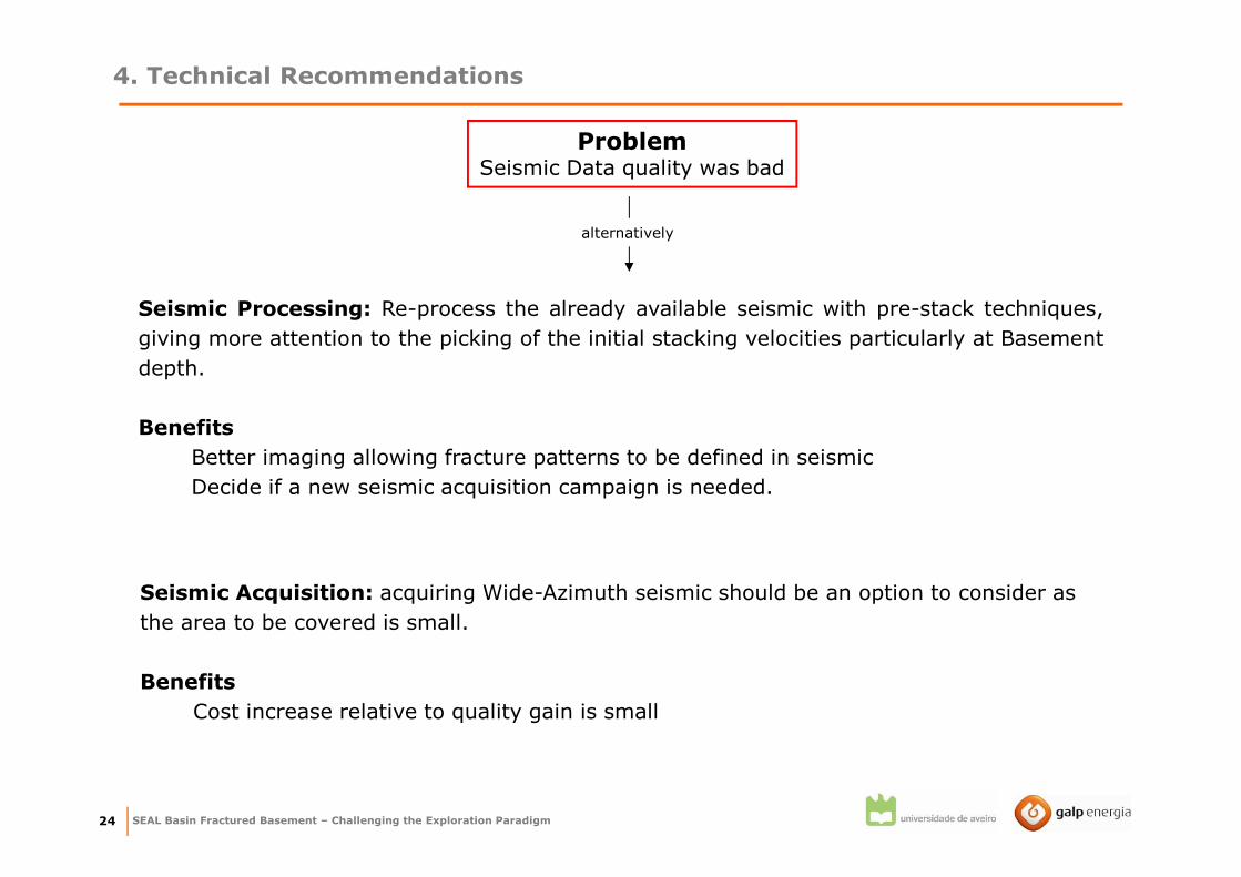
ProblemSeismic Data quality was bad
alternatively
Seismic Processing: Re-process the already available seismic with pre-stack techniques,
giving more attention to the picking of the initial stacking velocities particularly at Basement
depth.
Benefits
Better imaging allowing fracture patterns to be defined in seismic
Decide if a new seismic acquisition campaign is needed.
Seismic Acquisition: acquiring Wide-Azimuth seismic should be an option to consider as
the area to be covered is small.
Benefits
Cost increase relative to quality gain is small
SEAL Basin Fractured Basement – Challenging the Exploration Paradigm25
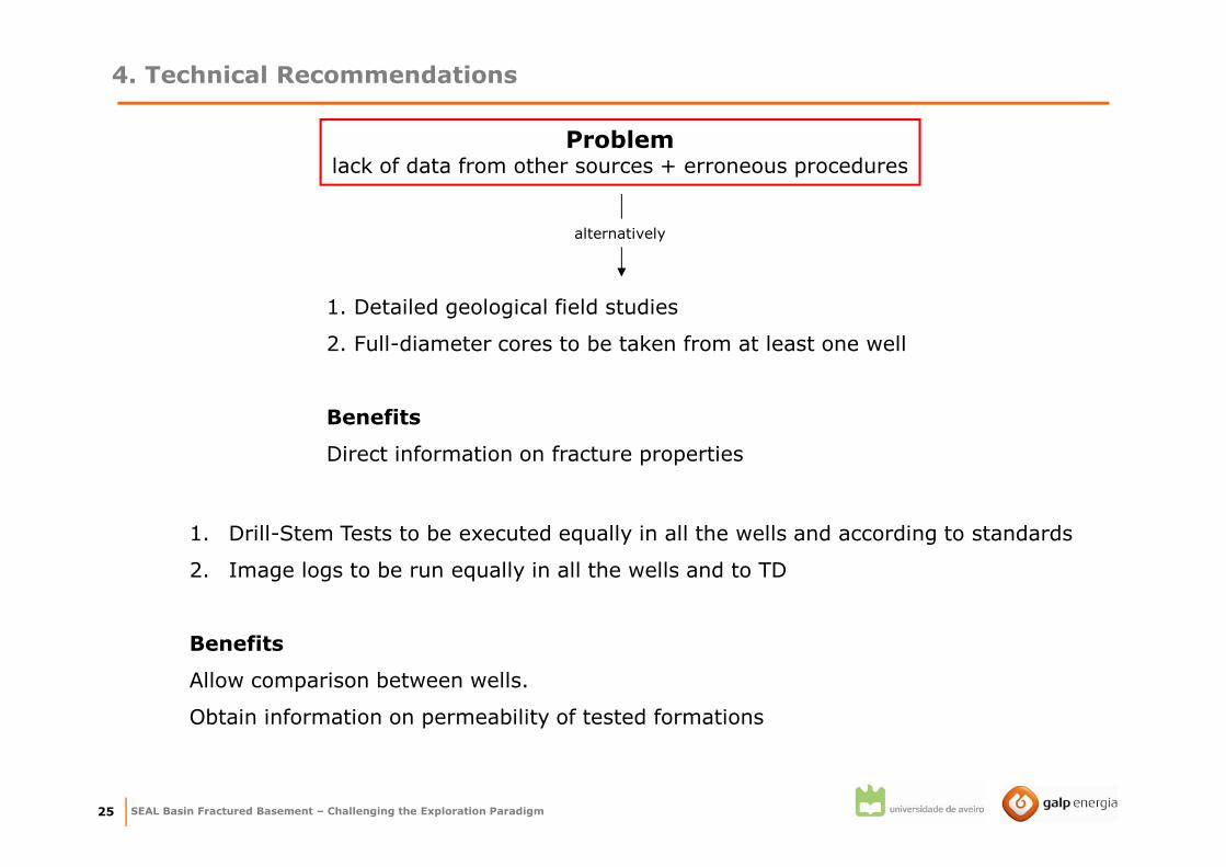
Problemlack of data from other sources + erroneous procedures
alternatively
1. Drill-Stem Tests to be executed equally in all the wells and according to standards
2. Image logs to be run equally in all the wells and to TD
Benefits
Allow comparison between wells.
Obtain information on permeability of tested formations
4. Technical Recommendations
1. Detailed geological field studies
2. Full-diameter cores to be taken from at least one well
Benefits
Direct information on fracture properties

SEAL Basin Fractured Basement – Challenging the Exploration Paradigm26
Problemwells were vertical and overbalanced.
alternatively
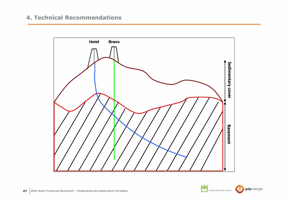
Directional drilling: directional wells at an angle from vertical in a direction normal to
fracture planes and parallel to the minimum in situ stress. Intersect fracture Family A!!!
Benefits
Maximises Contact of well with fractures, increasing productivity.
4. Technical Recommendations
Family A N22ºW/60ºNE
Hotel Well30º,240º
Well
W
N60ºE
N
E
S
N22ºW
Family A Fractures
Direction of Well
Well
W
N60ºE
N
E
S
N22ºW
Family A Fractures
Direction of Well
N60ºE
N
E
S
N22ºW
Family A Fractures
Direction of Well
X=180-(60+90)
X=30º
60º
90º
x
Inclination of Well
NE SW
X=180-(60+90)
X=30º
60º
90º
x
Inclination of Well
NE SW
SEAL Basin Fractured Basement – Challenging the Exploration Paradigm27
BravoHotel
Ba
sem
en
tS
ed
ime
nta
ry co
ve
r
BravoHotel
Ba
sem
en
tS
ed
ime
nta
ry co
ve
r
4. Technical Recommendations
SEAL Basin Fractured Basement – Challenging the Exploration Paradigm28
4. Technical Recommendations
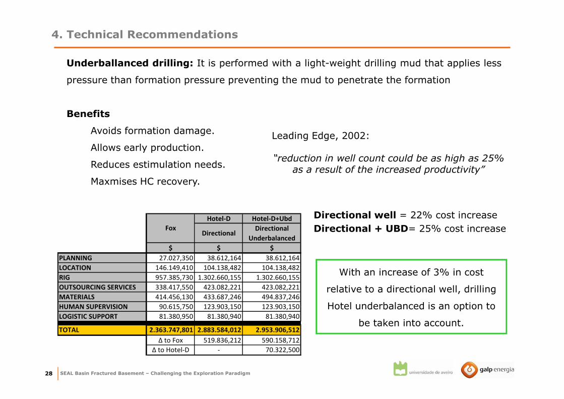
Underballanced drilling: It is performed with a light-weight drilling mud that applies less
pressure than formation pressure preventing the mud to penetrate the formation
Benefits
Avoids formation damage.
Allows early production.
Reduces estimulation needs.
Maxmises HC recovery.
Leading Edge, 2002:
“reduction in well count could be as high as 25% as a result of the increased productivity”
Hotel-D Hotel-D+Ubd
DirectionalDirectional
Underbalanced
$ $ $
PLANNING 27.027,350 38.612,164 38.612,164
LOCATION 146.149,410 104.138,482 104.138,482
RIG 957.385,730 1.302.660,155 1.302.660,155
OUTSOURCING SERVICES 338.417,550 423.082,221 423.082,221
MATERIALS 414.456,130 433.687,246 494.837,246
HUMAN SUPERVISION 90.615,750 123.903,150 123.903,150
LOGISTIC SUPPORT 81.380,950 81.380,940 81.380,940
TOTAL 2.363.747,801 2.883.584,012 2.953.906,512
Δ to Fox 519.836,212 590.158,712
Δ to Hotel-D - 70.322,500
Fox
Directional well = 22% cost increase
Directional + UBD= 25% cost increase
With an increase of 3% in cost
relative to a directional well, drilling
Hotel underbalanced is an option to
be taken into account.

5. Final Considerations

SEAL Basin Fractured Basement – Challenging the Exploration Paradigm30
5. Final Considerations
1. From the analysis of the references in the literature, seismic, well data (FMI and DST
data), it was possible to conclude that the Basement rock in the study area is a NFR.
2. Using FMI data, application of geomechanical principles, DFN modelling and Φ/k
simulations it was possible to identify fracture Family A as the best candidate to be
intersected with a well.
4. Fracture densities and apertures are underestimated due to the relation vertical-well
VS sub-vertical fractures, this means that results will be probably better than predicted.
5. In order to achieve better results this thesis suggests that a directional and
underbalanced well that intersects Family A perpendicularly should be drilled in the
future.
3. Using data from the models it was possible to calculate volumes for the Fractured
Basement – It had never been done despite the two exploration campaigns!!!

SEAL Basin Fractured Basement – Challenging the Exploration Paradigm31
6. Naturally Fractured
Reservoirs Workflow as
proved to be efficient and will
be used by GALP to evaluate
other prospects were
fractured reservoirs may be
present.
FINAL CONCLUSION!!

Thank you for your attention!


