Page 1
8/13/2019 M.sc-rC-7 Direct Design Method 2
http://slidepdf.com/reader/full/msc-rc-7-direct-design-method-2 1/44
Direct Two-Way Or Punching Shear Force:
The direct shear force, V u, to be resisted by the slab-
column connection can be calculated as the totalfactored load on the area bounded by panel centerlines
around the column less the load applied within the area
defined by the critical shear perimeter.
This is to be calculated both at the column perimeter
and at the perimeter of drop panel, if present, using the
critical section defined in Figs. 12.18 and 12.19.
Page 2
8/13/2019 M.sc-rC-7 Direct Design Method 2
http://slidepdf.com/reader/full/msc-rc-7-direct-design-method-2 2/44
Edge Of Slab
d / 2
lesser than1) b2 / 2
2) 4h
b2
b1
Fig. 12.19. Critical Section For Edge Column.
Eccentric Punching Shear Force:
According to ACI 11.2.6.2, the shear stress resulting from
moment transfer by eccentricity of shear shall be assumed
to vary linearly about the centroid of the critical section.
Page 3
8/13/2019 M.sc-rC-7 Direct Design Method 2
http://slidepdf.com/reader/full/msc-rc-7-direct-design-method-2 3/44
bo = 2c1 + 2c2 + 4d
V u = qu [l1l2 – b1 b2]
C
C
C
AD
B
b1 = c1 + d
b2
=c2
+ d
c1
c2
Centroid
al axis
+
c
=
γf M u
γν M u
a) Slab-Column Connection
b) Critical Section For Shear
C
Cv =
Applied direction
of forces is shown.
c1 + d
c2 + d
c) Direct Shear
d) Eccentric Shear
e) Resultant Shear
Fig. 12.20. Two-Way Shear Acting on CriticalSlab Section Around Column.
Page 4
8/13/2019 M.sc-rC-7 Direct Design Method 2
http://slidepdf.com/reader/full/msc-rc-7-direct-design-method-2 4/44
The resultant shear stress acting on the critical perimeter,
considering moment acting from both the directions, may be written as follows:
vu at face AB = ± ±c
u
A
V ( )
1
2
1
1
c
uu
J
b
M
γ ( )
2
2
2
2
c
uu
J
b
M
γ
Where, Ac and J c are calculated for the faces of a box-like shape defined by the assumed vertical failure
section.
Ac = perimeter area of the critical section
= bod = 2(b1 + b2) d
Page 5
8/13/2019 M.sc-rC-7 Direct Design Method 2
http://slidepdf.com/reader/full/msc-rc-7-direct-design-method-2 5/44
J c = torsional constant, like polar moment of
inertia of the area Ac
= I x + I y
Torsional Constant For Interior Column:
The critical area subjected to punching shear is a three
dimensional area and hence the calculation of itstorsional constant is not as simple as for any planar area.
In order to get a reasonably good estimate, the width ofthe area may be squeezed to zero but maintaining the
original area.
Page 6
8/13/2019 M.sc-rC-7 Direct Design Method 2
http://slidepdf.com/reader/full/msc-rc-7-direct-design-method-2 6/44
Centroidal axis of
the critical area
Moment in b1
direction
b2
b1
z
x
y
d
A
B
C
D
(a)Critical Perimeter Section OverInterior Column.
y
x
A = b2 d A = b2 d
A = 2b1 d
(b)2-D Area Equivalent to Area in (a)Looking From z-Direction.
Fig. 12.21. Critical Section For Two-Way Shear Over Interior Column.
Page 7
8/13/2019 M.sc-rC-7 Direct Design Method 2
http://slidepdf.com/reader/full/msc-rc-7-direct-design-method-2 7/44
J c
= I x
for faces AD and BC + I x
for faces AB and CD
+ I y for faces AD and BC + I y for faces AB and CD
= 2 × + 0 + 2 × + 2 ×
+ 012
3
1d b
+ 0
12
3
1db
( )
2
1
2 2
b
d b
=266
2
12
3
1
3
1 bdbdbd b++
Torsional Constant For Edge Column:
x1 = =( )d bd b
bd b
21
11
222
+ 21
2
1
2 bbb+
Ac = (2b1 + b2) d
Page 8
8/13/2019 M.sc-rC-7 Direct Design Method 2
http://slidepdf.com/reader/full/msc-rc-7-direct-design-method-2 8/44
z
y
x
C.A.
x1
b1
y
x
A = b2 d A = 2b1 d
(b)2-D Area Equivalent to Area in (a)
Looking From z-Direction.
Fig. 12.22. Critical Section For Two-Way Shear Over Edge Column.
J c
= ( )( )2
12
2
11
1
3
1
3
1
212122 xd b x
bd b
dbd b+
−++×
Page 9
8/13/2019 M.sc-rC-7 Direct Design Method 2
http://slidepdf.com/reader/full/msc-rc-7-direct-design-method-2 9/44
Torsional Constant For Corner Column:
y
x
A = b2 d A = b1 d
(b)2-D Area Equivalent to Area in (a)
Looking From z-Direction.
z
y
x
C.A.
x1
b1
b2
Fig. 12.23. Critical Section For Two-Way Shear Over Corner Column.
Page 10
8/13/2019 M.sc-rC-7 Direct Design Method 2
http://slidepdf.com/reader/full/msc-rc-7-direct-design-method-2 10/44
x1 = =( )d bd b
bd b21
11 2+ 21
2
1
2 bbb+
Ac = (b1 + b2) d
J c = ( )( )2
12
2
11
1
3
1
3
1
21212
xd b xb
d bdbd b
+
−++
Concrete Punching Shear Strength (V c):
According to ACI 11.12.2.1, for non-prestressed slabsand footings, V c shall be the smallest of:
a) V c = bod c f ′
+ β
2
16
1
Page 11
8/13/2019 M.sc-rC-7 Direct Design Method 2
http://slidepdf.com/reader/full/msc-rc-7-direct-design-method-2 11/44
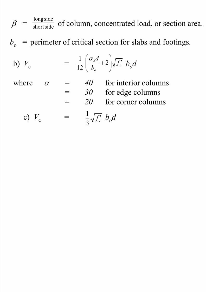
β = of column, concentrated load, or section area.sideshort
sidelong
bo = perimeter of critical section for slabs and footings.
b) V c = bod
where α = 40 for interior columns= 30 for edge columns
= 20 for corner columns
c
o
s f b
d ′
+ 2
12
1 α
c) V c = bod c f ′
3
1
Page 12
8/13/2019 M.sc-rC-7 Direct Design Method 2
http://slidepdf.com/reader/full/msc-rc-7-direct-design-method-2 12/44
For design, maximum shear stress due to the factored
shear force and moment ≤ φ vn
where φ vn =
V s = 0, when no shear reinforcement in slabs
in the form of shear heads.
( ) ( )d bV V o sc +φ
Shear Head To Improve Strength
Against Punching Shear:
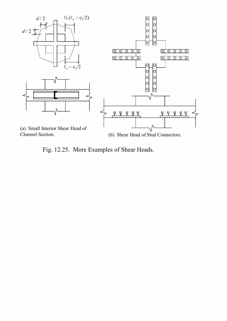
Four types of shear heads, shown in Figs. 12.24 and
12.25, may be designed over the top of columns in case
the concrete strength alone is not sufficient to resist theapplied punching shear.
Page 13
8/13/2019 M.sc-rC-7 Direct Design Method 2
http://slidepdf.com/reader/full/msc-rc-7-direct-design-method-2 13/44
d / 2
≤ d / 2
d / 2
Critical
Section
lv − c1/2
¾ (lv − c1/2)
(a) Stirrup Shear Reinforcement.(b) Large Interior Shear Head of
Channel Sections.
Fig. 12.24. Typical Shear Heads.
Page 14
8/13/2019 M.sc-rC-7 Direct Design Method 2
http://slidepdf.com/reader/full/msc-rc-7-direct-design-method-2 14/44
lv − c1/2
¾ (lv − c1/2)d / 2
d / 2
(a) Small Interior Shear Head of
Channel Section. (b) Shear Head of Stud Connectors.
Fig. 12.25. More Examples of Shear Heads.
Page 15
8/13/2019 M.sc-rC-7 Direct Design Method 2
http://slidepdf.com/reader/full/msc-rc-7-direct-design-method-2 15/44
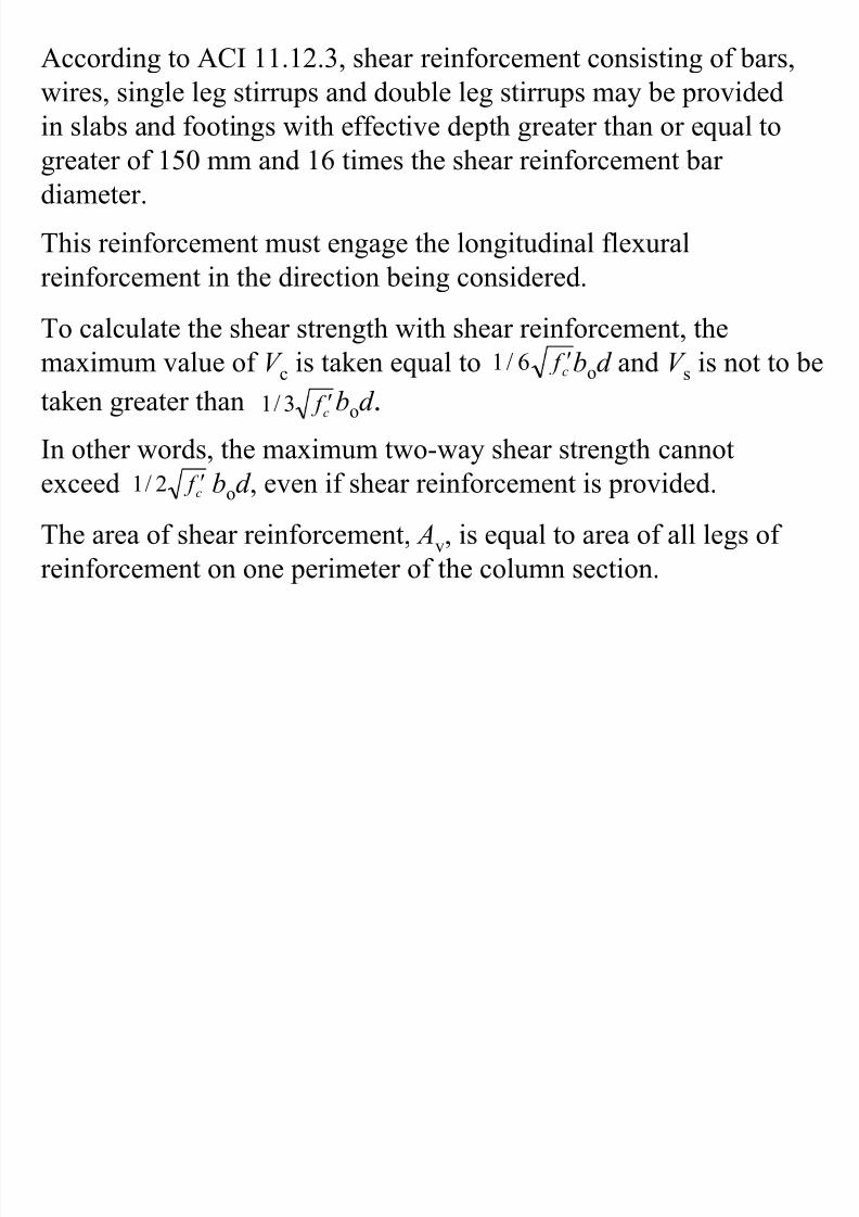
According to ACI 11.12.3, shear reinforcement consisting of bars,
wires, single leg stirrups and double leg stirrups may be provided
in slabs and footings with effective depth greater than or equal to
greater of 150 mm and 16 times the shear reinforcement bar
diameter.
This reinforcement must engage the longitudinal flexural
reinforcement in the direction being considered.
To calculate the shear strength with shear reinforcement, themaximum value of V c is taken equal to bod and V s is not to be
taken greater than bod .c f ′6/1
c f ′3/1
In other words, the maximum two-way shear strength cannotexceed bod , even if shear reinforcement is provided.c f ′2/1
The area of shear reinforcement, Av, is equal to area of all legs of
reinforcement on one perimeter of the column section.
Page 16
8/13/2019 M.sc-rC-7 Direct Design Method 2
http://slidepdf.com/reader/full/msc-rc-7-direct-design-method-2 16/44
• The distance between the column face and the first lineof stirrup legs that surround the column must not exceed
d /2.
• The spacing parallel to the column face between thestirrups in this first line must not exceed 2d .
• The spacing between successive lines of shearreinforcement that surround the column must not exceedd /2 measured in a direction perpendicular to the columnface.
• Structural steel I− and channel−shaped sections are alsoallowed in the slabs.
• Arms of the shear-head must not be interrupted within
the column sections.
Page 17
8/13/2019 M.sc-rC-7 Direct Design Method 2
http://slidepdf.com/reader/full/msc-rc-7-direct-design-method-2 17/44
• The section should not be a depth greater than 70
times the web thickness of the steel shape.• All compression flanges of the structural shapes
are to be located within 0.3d of compression
surface of the slab and these sections may be
considered to be effective in resisting the
moments besides providing the shear strength.• The ratio (a
v) between the flexural stiffness of
each shear-head arm and that of the surroundingcomposite cracked slab section of width (c
2+ d )
must not be less than 0.15.
Page 18
8/13/2019 M.sc-rC-7 Direct Design Method 2
http://slidepdf.com/reader/full/msc-rc-7-direct-design-method-2 18/44
Example 12.1: Perform check for punching
shear of a two-way slab system (Fig. 12.26) at thegiven edge column. The panel size is 6m × 8m and
all conditions of direct design method are satisfied.The other related data is as under:
qu = 11,000 Pa M
u(unbalanced)= 200 kN-m
f c′ = 25 MPah = 230 mm
d = 190 mm
Page 19
8/13/2019 M.sc-rC-7 Direct Design Method 2
http://slidepdf.com/reader/full/msc-rc-7-direct-design-method-2 19/44
Solution:
β = longer / shorter sides ratio for the column = 2.0
600mm
1200mm 8 m
3.5 m
Direction of
unbalanced
moment
200mm
Fig. 12.26. Slab System For Example 12.1.
Page 20
8/13/2019 M.sc-rC-7 Direct Design Method 2
http://slidepdf.com/reader/full/msc-rc-7-direct-design-method-2 20/44
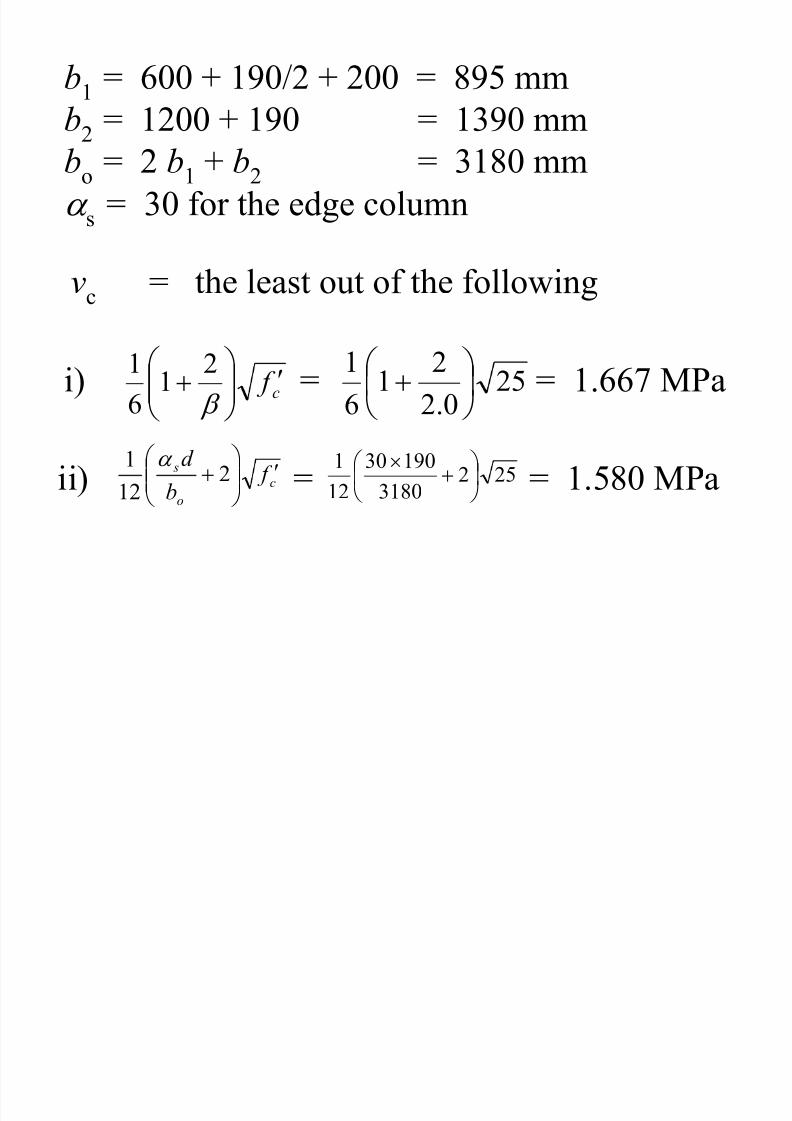
b1
= 600 + 190/2 + 200 = 895 mm
b2
= 1200 + 190 = 1390 mm
bo
= 2 b1
+ b2
= 3180 mm
α s = 30 for the edge column
vc
= the least out of the following
i) = = 1.667 MPac f ′
+
β
21
6
125
0.2
21
6
1
+
ii) = = 1.580 MPac
o
s f b
d ′
+ 2
12
1 α 252
3180
19030
12
1
+×
Page 21
8/13/2019 M.sc-rC-7 Direct Design Method 2
http://slidepdf.com/reader/full/msc-rc-7-direct-design-method-2 21/44
iii) = = 1.667 MPac f ′
3
125
3
1
φ vc
= 0.75 × 1.580 = 1.185 MPa
Ac
= bo × d = 3180 × 190 = 604,200 mm2
x1 = = = 252 mm21
2
1
2 bb
b
+ 13908952
8952
+×
J c
= ( )( )2
12
2
11
1
3
1
3
1
21212
2 xd b xb
d bdbd b
+
−++×
=
−××+×
+×
×233
2522
895190895
12
895190
12
1908952
( )( )22521901350 ×+
Page 22
8/13/2019 M.sc-rC-7 Direct Design Method 2
http://slidepdf.com/reader/full/msc-rc-7-direct-design-method-2 22/44
J c
= 5,349,563 × 104 mm4
γ f
= = = 0.651
2
1
3
21
1
b
b+
1390
895
3
21
1
+
γ f
= 1 − γ f
= 0.349
More flexural steel is to be provided near the column, ina width of c2 + 3h, to transfer 65.1% of moment.
Direct shear force, V u = qu [length × width – b1 b2]
= = 294.3 kN( )( ) ( )( )[ ]390.1895.085.31000
000,11−
Page 23
8/13/2019 M.sc-rC-7 Direct Design Method 2
http://slidepdf.com/reader/full/msc-rc-7-direct-design-method-2 23/44
Direct shear stress = V u / Ac = 294.3 × 1000 / 604,200
= 0.487 MPaEccentric shear =
c
u
J
x M 1ν γ
= = 0.329 MPa4
6
10563,349,5
25210200349.0
××××
Total applied shear, ν u = 0.486 + 0.329 = 0.815 MPa
ν u ≤ φν c ⇒ The slab is safe against two-way shear .
If ν u > φν c , following solutions are possible:
* Design a shear head.
* Provide drop panels or column capitals.
* Slightly increase the depth of slab if the differenceof ν u and φν c is smaller .
Page 24
8/13/2019 M.sc-rC-7 Direct Design Method 2
http://slidepdf.com/reader/full/msc-rc-7-direct-design-method-2 24/44
Example 12.2: Design reinforcement for the interior
panel of the flat plate floor system, shown in Fig. 12.27.Assume that direct design method is applicable and the
depth criterion is satisfied using a depth of 220 mm.
Check the depth of slab for shear considering the effect ofeccentric shear equal to 15% of the direct shear for this
interior panel. The other related data is as under:
Live load = 300 kgs/m2
Floor finish and partitions = 150 kgs/m2
M u (unbalanced) = 200 kN-m f c′ = 25 MPa
f y = 300 MPa
h = 220 mm
Page 25
8/13/2019 M.sc-rC-7 Direct Design Method 2
http://slidepdf.com/reader/full/msc-rc-7-direct-design-method-2 25/44
750 mm φ Columns
6m
8m
Fig. 12.27. Typical Interior Panel of Slab System For Example 12.2.
Page 26
8/13/2019 M.sc-rC-7 Direct Design Method 2
http://slidepdf.com/reader/full/msc-rc-7-direct-design-method-2 26/44
Solution:
Equivalent square column side, h =4
π (750) = 665 mm
qL = 300 N/m2
qD = 0.220 × 2400 + 150 = 678 N/m2
qu
= [1.2(qD
) + 1.6(qL
)] × 9.81 / 1000
= [1.2(678) + 1.6(300)] × 9.81 / 1000
= 12.69 kN/m2
The column and middle strips are shown in Fig. 12.28.
Page 27
8/13/2019 M.sc-rC-7 Direct Design Method 2
http://slidepdf.com/reader/full/msc-rc-7-direct-design-method-2 27/44
665mm square2.5m
1.5m
1.5m = Half
Middle Strip
Column
Strip
1.5m
1.5m
1.5m
Fig. 12.28. Equivalent Columns And Column And Middle Strips.
Page 28
8/13/2019 M.sc-rC-7 Direct Design Method 2
http://slidepdf.com/reader/full/msc-rc-7-direct-design-method-2 28/44
1. E−W Span
l1 = 8ml2 = 6m
ln
= 8.0 – 0.665 = 7.335 m
l2w = 6.0 m
M o = qu 8
2
2 nw ll
= (12.69)
( )( )8
335.70.62
= 512.1 kN-m
Support Section (Top steel, E–W Direction)
M
−
= 0.65 M o = 0.65 (512.1) = 332.9 kN-m A = l2/l1 = 0.75
α f1 = 0 (no beam), D = 0
%age CS moment out of positive moment = 75%%age CS moment out of positive moment = 60%
Page 29
8/13/2019 M.sc-rC-7 Direct Design Method 2
http://slidepdf.com/reader/full/msc-rc-7-direct-design-method-2 29/44
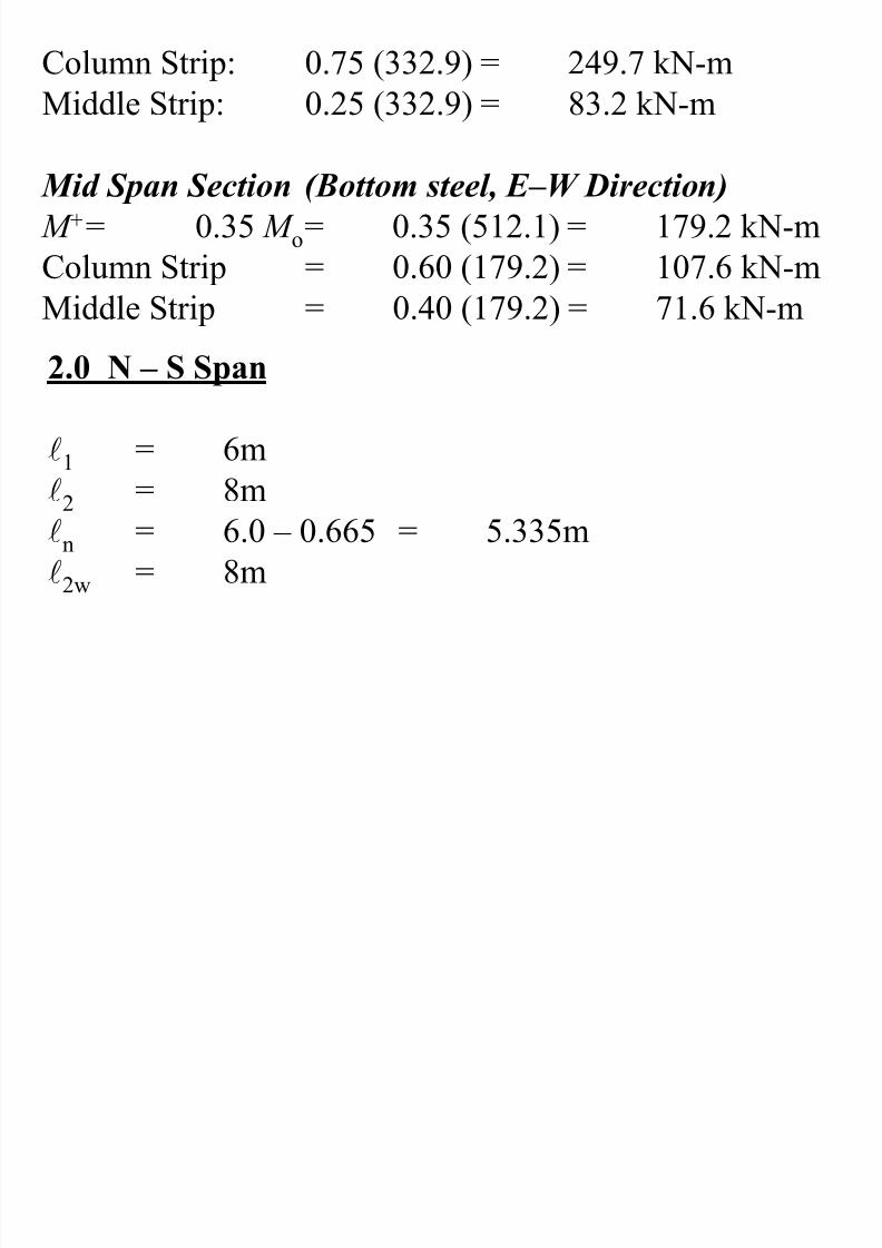
Column Strip: 0.75 (332.9) = 249.7 kN-m
Middle Strip: 0.25 (332.9) = 83.2 kN-m
Mid Span Section (Bottom steel, E–W Direction)
M +
= 0.35 M o= 0.35 (512.1) = 179.2 kN-mColumn Strip = 0.60 (179.2) = 107.6 kN-m
Middle Strip = 0.40 (179.2) = 71.6 kN-m
2.0 N – S Span
l1 = 6m
l2 = 8m
ln = 6.0 – 0.665 = 5.335m
l2w = 8m
Page 30
8/13/2019 M.sc-rC-7 Direct Design Method 2
http://slidepdf.com/reader/full/msc-rc-7-direct-design-method-2 30/44
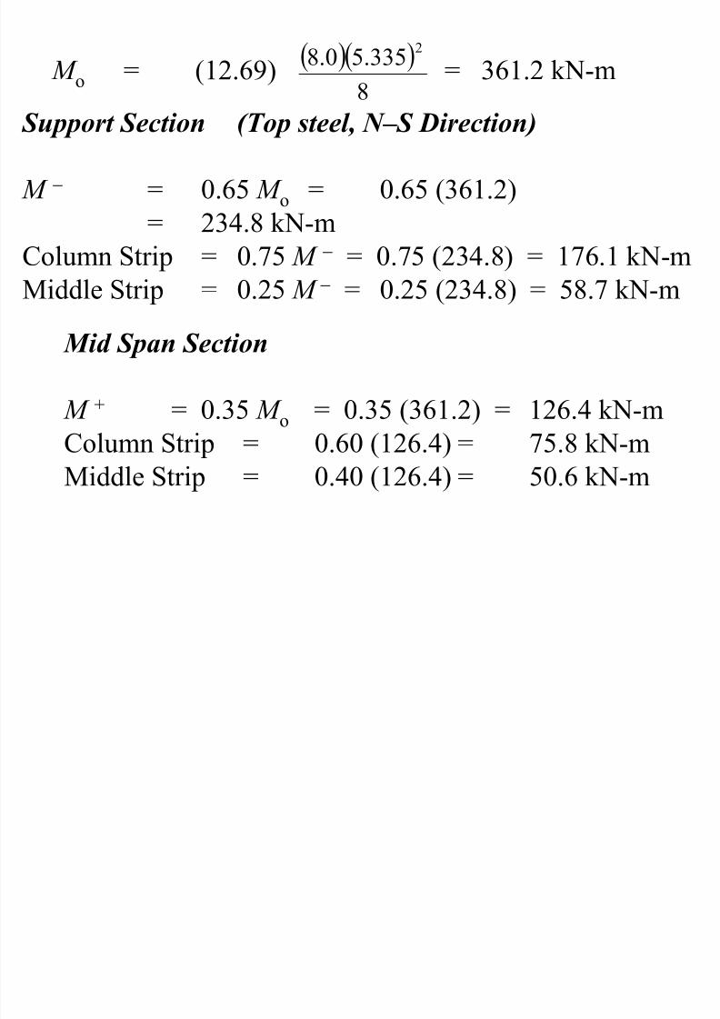
M o = (12.69) = 361.2 kN-m( )( )
8
335.50.82
Support Section (Top steel, N–S Direction)
M − = 0.65 M o = 0.65 (361.2)= 234.8 kN-m
Column Strip = 0.75 M − = 0.75 (234.8) = 176.1 kN-m
Middle Strip = 0.25 M − = 0.25 (234.8) = 58.7 kN-m
Mid Span Section
M + = 0.35 M o = 0.35 (361.2) = 126.4 kN-m
Column Strip = 0.60 (126.4) = 75.8 kN-m
Middle Strip = 0.40 (126.4) = 50.6 kN-m
Page 31
8/13/2019 M.sc-rC-7 Direct Design Method 2
http://slidepdf.com/reader/full/msc-rc-7-direct-design-method-2 31/44
3m
3m
3m
3m′3m 5m
176.1
176.1
176.1
176.1
249.7 249.7
249.7 249.7
75.8 75.8
83.2 83.2
58.7
58.7
107.6
107.6
71.6
50.6
Fig. 12.29. Moments Across Full Width of Strips For Example 12.2.
Page 32
8/13/2019 M.sc-rC-7 Direct Design Method 2
http://slidepdf.com/reader/full/msc-rc-7-direct-design-method-2 32/44
smax = 2h = 440 mm
d = 220 − 20 − 16 − 6 = 178 mm(lesser value for the inner steel)
ρ min = 0.0020 , As,min = 0.002 × 1000 × 220
= 440 mm2/m width
Page 33
8/13/2019 M.sc-rC-7 Direct Design Method 2
http://slidepdf.com/reader/full/msc-rc-7-direct-design-method-2 33/44
Table 12.12. Calculation of Slab Steel For Example 12.2.
Design
Frame
Location Strip Width
mm
Mu
kN-m
R
= M u/bd 2
As
mm2
Steel
E-W Support
Top steel
CS 3000 249.7 2.627 0.0106 1887 #19@150mm c/c
MS 3000 83.2 0.875 0.0033 587 #13@200mm c/c
E-W Mid-span
Bot. steel
CS 3000 107.6 1.132 0.0046 819 #13@150mm c/c
MS 3000 71.6 0.753 0.0029 516 #13@250mm c/c
N-S Support
Top steel
CS 3000 176.1 1.853 0.0076 1353 #19@200mm c/c
MS 5000 58.7 0.371 0.0025 445 #10@160mm c/c
N-S Mid-span
Bot. steel
CS 3000 75.8 0.797 0.0033 587 #13@200mm c/c
MS 5000 50.6 0.319 0.0025 445 #10@160mm c/c
Page 34
8/13/2019 M.sc-rC-7 Direct Design Method 2
http://slidepdf.com/reader/full/msc-rc-7-direct-design-method-2 34/44
Table 12.13. Curtailment of Slab Steel For Example 12.2.
Design
Frame
Span Lengths Column Strip
+ ½ Eq. Column Size
Middle Strip
+ ½ Eq. Column Size
l1
(mm)
ln
(mm)
0.30 ln
(mm)
0.20 ln
(mm)
0.22 ln
(mm)
0.15 ln
(mm)
E-W 8000 7335 2540 1800 1950 1430
N-S 6000 5335 1940 1400 1510 1130
Page 35
8/13/2019 M.sc-rC-7 Direct Design Method 2
http://slidepdf.com/reader/full/msc-rc-7-direct-design-method-2 35/44
1400
1940
#10@160 (alt.)
150mm lap
Full tension
splice
1130
1510
1510
#19@200 (alt.)
#13@200 (alt.)
#10@160
Page 36
8/13/2019 M.sc-rC-7 Direct Design Method 2
http://slidepdf.com/reader/full/msc-rc-7-direct-design-method-2 36/44
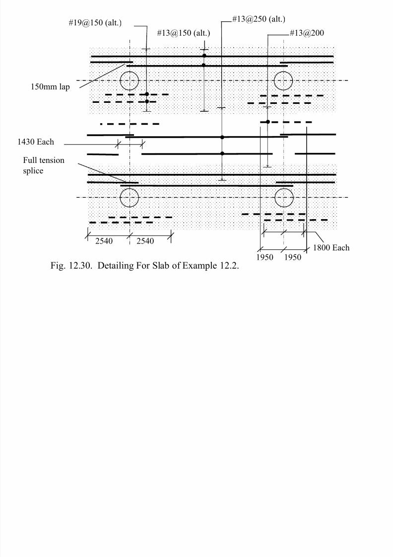
150mm lap
Full tension
splice
1430 Each
2540
1950 1950
#13@250 (alt.)
#13@150 (alt.) #13@200
#19@150 (alt.)
25401800 Each
Fig. 12.30. Detailing For Slab of Example 12.2.
Page 37
8/13/2019 M.sc-rC-7 Direct Design Method 2
http://slidepdf.com/reader/full/msc-rc-7-direct-design-method-2 37/44
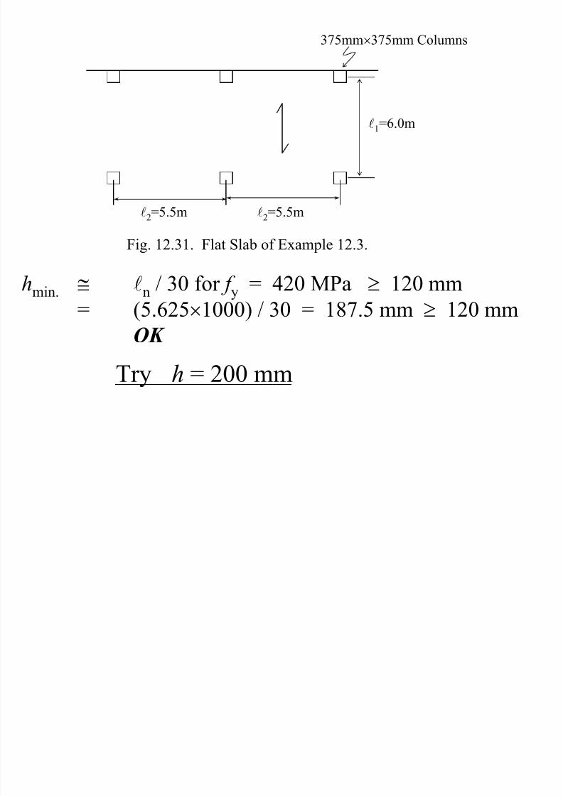
Example 12.3: Calculate the design moments for the
exterior panel of the flat plate system given in Fig. 12.31, perpendicular to the edge. The other related data is as
under:
Clear cover = 20 mm
Grade of steel = 420 MPa
Superimposed qD = 150 kgs/m2
Live load qL = 300 kgs/m2
f c′ = 20 MPa
Solution:
Longer ln = (6000 – 375) / 1000 = 5.625 m
Page 38
8/13/2019 M.sc-rC-7 Direct Design Method 2
http://slidepdf.com/reader/full/msc-rc-7-direct-design-method-2 38/44
375mm×375mm Columns
l2=5.5m
l1=6.0m
l2=5.5m
Fig. 12.31. Flat Slab of Example 12.3.
hmin.
≅ ln
/ 30 for f y
= 420 MPa ≥ 120 mm
= (5.625×1000) / 30 = 187.5 mm ≥ 120 mm
OK
Try h = 200 mm
Page 39
8/13/2019 M.sc-rC-7 Direct Design Method 2
http://slidepdf.com/reader/full/msc-rc-7-direct-design-method-2 39/44
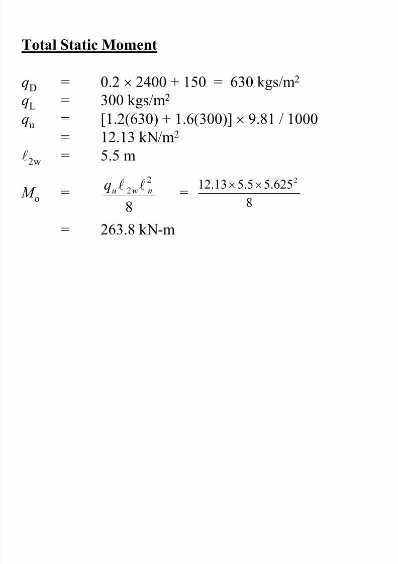
Total Static Moment
qD = 0.2 × 2400 + 150 = 630 kgs/m2
qL = 300 kgs/m2
qu = [1.2(630) + 1.6(300)] × 9.81 / 1000
= 12.13 kN/m2
l2w = 5.5 m
M o = =
= 263.8 kN-m8
2
2 nwuq ll
8
625.55.513.12 2××
Page 40
8/13/2019 M.sc-rC-7 Direct Design Method 2
http://slidepdf.com/reader/full/msc-rc-7-direct-design-method-2 40/44
Longitudinal Distribution Of Moments
Mo = 263.8
Int. M =0.70Mo = −184.7kN-m
M+ = 0.52Mo = +137.2kN-m
Ext. M =0.26Mo = −68.6kN-m
Torsional Member
There is no edge beam and 375mm width of slab may be
assumed to act as a torsion member, as shown in Fig.12.32.
Page 41
8/13/2019 M.sc-rC-7 Direct Design Method 2
http://slidepdf.com/reader/full/msc-rc-7-direct-design-method-2 41/44
L-section in l2 direction
x = 200mm
y = 375mm
X-section inl
1direction
8″
5500mm
Fig. 12.32. Torsion Member For Example 12.3.
C = = 66,400 × 104 mm4
363.01
3 y x
y
x∑
−
I s = = 366,667 × 104 mm4
12
2005500 3×
Page 42
8/13/2019 M.sc-rC-7 Direct Design Method 2
http://slidepdf.com/reader/full/msc-rc-7-direct-design-method-2 42/44
β t
=
= = 0.09
scs
cb
I E
C E
2
( )( )4
4
10667,3662
10400,66
×
×
A = l2 / l1 = 5.5 / 6.0 = 0.917
B = β t = 0.09
α f1 = 0 ⇒ D = = 0
1
21
l
l
f α
Transverse Distribution Of Moments
The column strip moment percentages are calculated asunder:
Page 43
8/13/2019 M.sc-rC-7 Direct Design Method 2
http://slidepdf.com/reader/full/msc-rc-7-direct-design-method-2 43/44
Int. M − = 75 + 30(1− A) D = 75%
Ext. M − = 100 − 10 B + 12 BD(1 − A) = 99.1%
M + = 60 + 15(3−2 A) D = 60%
Mo = 263.8
Int. M =0.70Mo = −184.7kN-m
M+ = 0.52Mo = +137.2kN-m
Ext M =0.26Mo = −68.6kN-m
CS = 0.75(−184.7) = 138.5kN-m
MS = 0.25(−184.7) = 46.2kN-m
CS = 0.60(137.2) = 82.3kN-m
MS = 137.2−82.3 = 54.9kN-m
CS = −68.0k-ft (99.1%)
MS = very small
Page 44
8/13/2019 M.sc-rC-7 Direct Design Method 2
http://slidepdf.com/reader/full/msc-rc-7-direct-design-method-2 44/44
Continued on next file