8
Product Information MSE 1000 Modular Electronic Unit for Multipoint Inspection Apparatuses May 2013

Product Information
MSE 1000Modular Electronic Unit for Multipoint Inspection Apparatuses
May 2013

2
MSE 1000Modular electronic unit for multipoint inspection apparatuses
Production-integrated measurement is one of the central demands of modern manufacturing. Unlike a total measurement on a coordinate measuring machine in a separate room, special measuring apparat-uses in the production department can minimize the duration of measurement and enable the operator to rapidly adapt processes based on the measurement results. At the same time, such measuring apparatuses—which can be designed as stations for statistical process control (SPC)—also serve for statistical evaluation of the measured values and thus permit a qualified process control. They can be equipped with a large number of differing measuring devices.
The following stringent requirements for the subsequent electronics can be met with the MSE 1000 modular electronic unit from HEIDENHAIN:
Flexibility for adaptation to differing •conditions of operationsA variety of interfaces for connection of •numerous measuring devicesFast communication with higher-level •computer systems over EthernetOutputs for controlling sorting switches, •warning lamps, PLC, etc.Output of measurement results for •documentation and further processing
DesignThe user installs the MSE 1000 as a series of modules and configures it for his specific requirements. The individual modules permit connection of incremental, absolute and analog measurands, the output of switch signals, and communica-tion over diverse interfaces. In all, up to 250 axes or channels can be configured. In its basic configuration, the MSE 1000 consists of a power module and a basic module. It can be expanded by further modules as needed.
MountingThe MSE 1000 modules are easily mounted on a standard rail in a cabinet or on a mounting bracket (accessory). The individual modules are plugged onto each other and fixed together with a lock. This also connects the internal bus and the power supply. The module widths are selected so that the MSE 1000 is also suitable for a 19” housing.
FunctionsThe functions of the MSE 1000 are defined by the PC software used.
MSEsetupThis software package is available for down-load on www.heidenhain.de. It handles the basic functions of the MSE 1000:
Configuration (modules, encoder inputs, •data transmission)Diagnostics•Data transfer to the PC•Writing the measured values to an •Excel table
Program libraryThe program library (DLL) for Windows systems is required if the MSE 1000 is to be operated with a customer-specific software application. The Ethernet Program Library provides functions that permit communica tion between the MSE 1000 and PC.
3
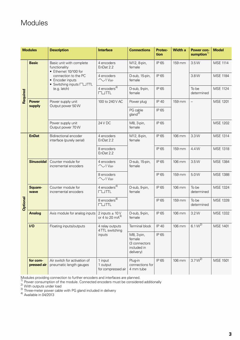
Modules
Modules Description Interface Connections Protec-tion
Width a Power con-sumption1)
Model
Req
uir
ed
Basic Basic unit with complete functionality
Ethernet 10/100 for •connection to the PCEncoder inputs•Switching inputs • « TTL (e.g. latch)
4 encodersEnDat 2.2
M12, 8-pin, female
IP 65 159 mm 3.5 W MSE 1114
3.8 W MSE 11844 encoders1 VPP
D-sub, 15-pin, female
IP 65
To be determined
MSE 11244 encoders4)
« TTLD-sub, 9-pin, female
IP 65
Power supply
Power supply unitOutput power 50 W
100 to 240 V AC Power plug IP 40 159 mm – MSE 1201
PG cable gland3)
IP 65
Power supply unitOutput power 70 W
24 V DC M8, 3-pin, female
IP 65 MSE 1202
Op
tio
nal
EnDat Bidirectional encoder interface (purely serial)
4 encodersEnDat 2.2
M12, 8-pin, female
IP 65 106 mm 3.3 W MSE 1314
8 encodersEnDat 2.2
IP 65 159 mm 4.4 W MSE 1318
Sinusoidal Counter module for incremental encoders
4 encoders1 VPP
D-sub, 15-pin, female
IP 65 106 mm 3.5 W MSE 1384
8 encoders1 VPP
IP 65 159 mm 5.0 W MSE 1388
Square-wave
Counter module for incremental encoders
4 encoders4)
« TTLD-sub, 9-pin, female
IP 65 106 mm To be determined
MSE 1324
8 encoders4)
« TTLIP 65 159 mm To be
determinedMSE 1328
Analog Axis module for analog inputs 2 inputs ± 10 Vor 4 to 20 mA4)
D-sub, 9-pin, female
IP 65 106 mm 3.2 W MSE 1332
I/O Floating inputs/outputs 4 relay outputs4 TTL switching inputs
Terminal block IP 40 106 mm 6.1 W2) MSE 1401
M8, 3-pin, female (3 connectors included in delivery)
IP 65
for com-pressed air
Air switch for activation of pneumatic length gauges
1 input1 outputfor compressed air
Plug-in connections for 4 mm tube
IP 65 106 mm 3.7 W2) MSE 1501
Modules providing connection to further encoders and interfaces are planned.1) Power consumption of the module. Connected encoders must be considered additionally2) With outputs under load3) Three-meter power cable with PG gland included in delivery4) Available in 04/2013

4
Specifications
Measuring channels/axes Up to 250
Data transfer rate 20 to 100 measured values per second for all axes; depends on the configuration
Data transfer Standard Ethernet, IEEE 802.3
Addressing Fixed IP address or DHCP
External latch inputs 2 (e.g. for foot switch)
Software MSEsetup: Graphic-supported configuration of the system, diagnosis of the encoders, loading of measured data to Excel
Program library for Windows (Linux and LabVIEW in preparation): Integration of the MSE 1000 in the Ethernet network for customer-specific software solutions
Power supply* 100 to 240 V AC or 24 V DC
Operating temperature 0 °C to 45 °C
Relative humidity 80 %
Degree of protection* IP 40, optionally IP 65
Mounting Top hat rail, on mounting bracket or in electrical cabinet (specially conceived for 19-inch cabinet)
Accessories Mounting bracket, foot switch, connecting cable
* Please select when ordering
Specifications
Example of power consumption calculationThe power supply module (MSE 1201, MSE 1202) provides the electrical power for further modules and encoders. If the power provided does not suffice to operate the desired system configuration, a further power supply module must be used.
The power consumption is specified for each module (see table). The power consumption of the connected HEIDENHAIN encoders can be calculated from the catalog data (supply voltage x current consumption). For all other consumers (e.g.. inductive and analog sensors), the connected load must be known. The sum power of all consumers must not exceed the rated power of the power supply module(s).
The following example illustrates this calculation.
Components to be suppliedEncoders: 8 x ACANTO AT 1217, 12 x SPECTO ST 1288, 2 x LS 388 C,
2 x temperature sensors 20 V/100 mAModules: 1 x MSE 1114 basic module, 1 x MSE 1314 axis module,
2 x MSE 1388 axis modules, 1 x MSE 1501 compressed-air module, 1 MSE 1332 analog module
Power calculation
Data from catalog and calculated Total power consumption (example)Operating
voltageCurrent consump-tion
Power consumption/unit
Num-ber of units
ACANTO AT 1217SPECTO ST 1288LS 388 CThermistor
5 V 5 V 5 V20 V
150 mA 90 mA100 mA100 mA
0.75 W0.45 W0.5 W2 W
812 2 2
6 W 5.4 W 1 W 4 W
MSE 1114MSE 1314MSE 1388MSE 1501MSE 1332
–––––
–––––
3.5 W3.3 W5 W3.7 W3.2 W
1 1 2 1 1
3.5 W 3.3 W10 W 3.7 W 3.2 W
Total: 40.1 W
This power consumption can be met by one MSE 1201 (50 W) or MSE 1202 (70 W) power supply module.

5
Pin layout » 1 VPP
Mating connector:15-pin D-sub connector
Power supply Incremental signals Others
4 12 2 10 1 9 3 11 14 7 5/6/8/15 13 /
UP SensorUP
0 V Sensor0 V
A+ A– B+ B– R+ R– Vacant Vacant Vacant
Brown/Green
Blue White/Green
White Brown Green Gray Pink Red Black / Violet Yellow
EnDat pin layoutMating connector:8-pin coupling, M12
Power supply Absolute position values
8 2 5 1 3 4 7 6
UP Sensor UP 0 V Sensor 0 V DATA DATA CLOCK CLOCK
Brown/Green Blue White/Green White Gray Pink Violet Yellow
InterfacesEncoders
Pin layout « TTLMating connector:9-pin D-sub connector (male)
Power supply Incremental signals Others Shield
7 6 2 3 4 5 9 8 1 Housing
UP 0 V Ua1 ¢ Ua2 £ Ua0 ¤ Vacant Case GND
BN/GN+BL WH/GN+WH
Brown Green Gray Pink Black Red /
Analog pin layoutMating connector:9-pin D-sub connector (male)
Power supply 1 Power supply 2 Shield Analog signal
1 4 3 9 6 5 Housing 8 2 7
TTL – 12 V + 12 V 0 V 5 V 0 V Shield Case GND UA IA IA
Power supplies 1 and 2 are galvanically isolated and must not be used simultaneously.UA: Analog voltage signal – 10 V to + 10 V; IA: Analog voltage signal 4 to 20 mA
Cable shield connected to housing; UP = Power supply voltageSensor: The sensor line is connected in the encoder with the corresponding power line.Vacant pins or wires must not be used!

6
Switching inputsThe switching inputs are active when a High signal (contact or pulse) is present. They are isolated and can be supplied externally or internally.
Specifications0 V UL 1.5 V4.5 V UH 26 VIL 25 mAtmin � 100 ms
Switching inputs for internal power supply
Switching inputs for external power supply
Relay outputs
SpecificationsUL 30 V DC/ACIL 0.05 AtD 25 ms
Inputs/Outputs
Relay outputs and switching inputs are integrated in the MSE 1401 input/output module. It is available in two versions.
IP 40 protection Electrical connections as terminalsIP 65 protection Electrical connections as individual M8 connecting elements
IP 40 terminal block
1) For switching inputs: Power supply (for use of internal power)
2) For relay outputs: Common connection
Output 4
Output 3
Output 2
Output 1
Input 4+
Input 4-
Input 3+
Input 3-
Input 2+
Input 2-
Input 1+
Input 1-

7
IP 65 relay outputsMating connector3-pin M8 coupling (female)
PIN Assignment
1 O Output
3 Vacant
4 Vacant
IP 65 relay inputsMating connector3-pin M8 coupling (female)
PIN Assignment
1 I+ Input
4 I–
3 Vacant
IP 65 power supplyMating connector3-pin M8 connector (female)
PIN Assignment
1 5 V DC For switching inputs:Power supply (for the use of internal power)4 0 V
3 COMMON OUT
For relay outputs:Common connection
The MSE 1202 power-supply module with 24 V DC supply has an M8 connector
Mating connector3-pin M8 connector (female)
PIN Assignment
1 24 V DC Power supply
3 0 V
4 Vacant
Power supply unit

Accessories
Mounting bracketFor mounting the MSE on a (table) surface. Two mounting brackets are connected together by two standard top hat rails. Two rows of modules or one MSE can be connected to it and a cable channel can be fastened.ID 850752-01
Foot switchFor connection to the basic module, for triggering/latching measurements.Cable length: 4.5 mID 681041-03
Mating connector3-pin M8-coupling (male) for In- and Outputs MSE 1401 IP 65ID 1071953-01
3-pin M8-connector (female) for power supply of MSE 1202 and MSE 1401 IP 65ID 1071955-01
Connecting cableFor connecting two or more MSE rows, e.g. during mounting in the electrical cabinet.ID 850753-xx
Bend radius� 35 mm


