63
MSPA-1-AS • Service Manual • Visual step-by-step guide to easily identify & correct technical problems! GECKO

MSPA-1-AS• Service Manual •
Visual step-by-step guide to easily
identify & correct technical problems!
GECKO

Contents
PreliminaryRequired Material 3
Error Messages"FLO" 11"FLC" 15"Prr" 17"Prh" 19"HL" 21"FrE" 25
MiscellaneousParts List 59Wiring Diagram 61Professional Repair Kit 62
How toReplace the Board 51Replace the Heater 55Adjust the Pressure Switch 57
TroubleshootingNothing Works! 27Spa Is Not Heating! 31Pump 1 Does Not Work! 35Pump 2 Does Not Work! 38Blower Does Not Work! 41Spa Light Does Not Work! 45Ozonator Does Not Work! 47Keys Do Not Work! 49
ProgrammingJumper Setup 9
Power & Ground CheckGFCI 5Electrical Wiring 6GFCI Trips! 7

Service manual2
Important Safety Information
WARNING: Risk of electrical shock! All procedures described in this service manual must only be performed by qualified personnel, in accordance with the standards applicable in the country of installation and, whenever possible, with the equipment powered off. When connecting the equipment, always refer to the wiring diagram affixed to the inside of your spa pack’s power box cover! This diagram always prevails over the wiring diagram at the end of this manual.
All information given subject to technical modifications without notice.
In order to be as helpful as possible, most sections of this manual were written in two distinct formats: problem-solving solutions are described using both troubleshooting flow charts and step-by-step procedures.
They should be used in conjunction, flow charts giving a global overview of specific problems while step-by-step procedures are more detailed.
Although this manual has been prepared with great care, some information may seem erroneous or unclear to you. In this case, please do not hesitate to contact us with your remarks or questions.

3MSPA-1-AS
Tools & Test Equipment:
Pack Parts:
PliersPhillips & flat screwdrivers11/32" (M8) nut driver1/4" (M6) open-end wrench
3/8" (M10) open-end wrenchJumper cableMultimeterGFCI tester & digital thermometer (optional)
Temperature probeHigh-limit sensorMSPA-1-AS system board (or complete spa pack)
TransformerPressure switchFusesTop side control
The following tools, test equipment and components are necessary to perform service calls on an MSPA-1-AS Power Spa Pack.
Notes: The equipment delivered may slightly differ from the illustrations shown in this manual.
Gecko Electronics Inc. sells Professional Repair Kits that include everything needed for MSPA-1-AS Power Spa Pack servicing. For more information, go to the last page of this manual.
PRELIMINARYRequired Material

Service manual4
Notes:

5MSPA-1-AS
If the GFCI trips, follow the troubleshooting flow chart below to identify the source of the problem.
Is theGFCI
properlyconnected?
If theGFCI is
still tripping,disconnect
the power inputwires.
Is theGFCI stilltripping?
Replacethe GFCI.
Replacethe board.
The cableis defective.
Call anelectrician!
Replacethe
transformer.
Reconnectone component
at a timeuntil the
GFCI startstripping.
Replacethe defectivecomponent.
Verify theGFCI wiringdiagram &
reconnect it.
yes
yes no
no
yes no
Disconnect all outputs,
including the two wires of the
heater & the light cord.
Is the GFCI still tripping?
POWER & GROUND CHECKGFCI Flow Chart

Service manual6
Note: For systems manufactured before 1999, if P43 & P44 are missing, use a #6 gage (4 mm dia.) cable and install it between Line 1 and Line 2.
1 x 230 VAC (32 A) input supply wiring
Proper wiring of the electrical service box, GFCI and spa pack terminal block is essential.
• Make a visual inspection for signs of miswiring. Refer to the supplied wiring diagram. Call an electrician if necessary.
POWER & GROUND CHECK Electrical Wiring
INPUTCABLE
LINE
GROUND
LINE 1
NEUTRAL
LINE 2
NEUTRAL
USE OP-TIONALJUMPER
Jumper JMP1 set in "HC" mode!
Note: For systems manufactured before 1999, if P43 & P44 are missing, use a #6 gage (4 mm dia.) cable and install it between Line 1 and Line 2.
1 x 230 VAC (16 A) input supply wiring
Jumper JMP1 set in "LC" mode!
LINE
GROUND
LINE 1
NEUTRAL
LINE 2
NEUTRAL
USE OP-TIONALJUMPER
INPUTCABLE

7MSPA-1-AS
POWER & GROUND CHECKGFCI Trips!
1• Verify if the GFCI is properly connected.
2• If it is not, verify the GFCI wiring diagram and reconnect it.
If the equipment is connected but nothing seems to work, the power supply must be defective. Perform the following:
Note that in new installations, GFCI trippings due to miswiring are very common.
If the breaker is properly wired, GFCI trippings can occur when the total amount of current drawn by the spa exceeds the rating of the breaker. Such an occurrence, however, is very unlikely since each output of the spa pack is individually fused and fuses will blow before the GFCI trips.
A current leak to the ground will also make the GFCI trip. If one of the components is faulty and there is a leak of more than 5 mA, the GFCI will trip to prevent electrocution.
Several different models of GFCIs are available on the market. Note that our illustrations are generic.
3• If the GFCI is properly connected but still tripping, disconnect all outputs, including the two wires of the heater & the light cord.
4• If the GFCI still trips, replace the transformer.
5• If the GFCI still trips even after the transformer has been replaced:
a- Disconnect the power input wires.
If the GFCI still trips, the cable must be defective.
Call an electrician!
b- If the GFCI stops tripping, replace it.
c- If the GFCI is still tripping, replace the board referring to the "How to Replace the Board" section of this manual.
If it stops tripping, reconnect one com-ponent at a time until the GFCI starts tripping. Replace the defective com-ponent.

Service manual8
Notes:

9MSPA-1-AS
PROGRAMMINGJumper Setup
2• To change a setting, simply pull the jumper out using a pair of pliers and replace it in the desired position.
It is possible to change some parameters of your MSPA-1-AS Spa Pack by positioning specific jumpers located on the board.
To access the jumpers, first remove the plastic cover inside your MSPA-1-AS Spa Pack power box referring to the "How to Replace the Board" section of this manual.
On your system, jumper functions may differ from the following. Check the supplied wiring diagram affixed to the inside of the power box metal cover for your spa pack’s specific functions.
Jumper location
Position 2Position 1
1• The jumpers are located on the upper right section of the board.
Jumper JMP1: Current limiting option
Jumper JMP1 is used to limit the current drawn when the 2 pumps are used.
Position 1 (HC): The heater may not be turned on at the same time as pump 2. Position 2 (LC): Pump 2 is disabled. Also, the heater may not be turned on if pump 1
is running at high speed or if the blower is on.
Jumper JMP2: Temperature display unit
Position 1: Temperature will be displayed in degrees Fahrenheit (ºF).
Position 2: Temperature will be displayed in degrees centigrade [Celsius] (ºC).
Jumper JMP3: Pump 1
Position 1: Two-speed pump.
Position 2: Single-speed pump.
Jumper JMP4: Pump 2
Position 1: Two-speed pump.
Position 2: Single-speed pump.

Service manual10
Notes:

11MSPA-1-AS
Replace thepressure
switch cable.
ERROR MESSAGES"FLO" Flow ChartThe "FLO" message indicates a problem with the pressure switch. Pump is on but no water pressure is detected. Follow the troubleshooting flow chart below to identify the source of the problem.
Notes: For systems manufactured before 1998, you have to press a key after each step to reset the system.
The heater barrel has to be installed on the pressure side of the pump and not on the suction side.
Is the pumprunning?
Refer to the "Pump Does Not Work" section.
Remove anything that may be
obstructingthe filter.Clear anyair locks& verify
the watervalves.
Verify if thepressure switch
cable is properly connected
to the pressure switch and
to the board.
Verify if the spa pack contains enough water to operate properly.
yes no
Is there anything limitingthe flow of water in the piping?
yes no
Is the installationrecent (less than
two years)?
Replace thepressure switch.
Adjust thepressure switch.
Make sure there is a flow ofwater in the heater and short
the two terminals of the pressure switch with a jumper cable.
Does the "FLO" messagedisappear?
yes no
yes no
Replacethe board.

Service manual12
ERROR MESSAGES "FLO" Error MessageThe "FLO" error message is displayed when a problem is detected with the pressure switch. The system does not detect any pressure when the pump is (whether manually or automatically) activated.
Note: The heater barrel has to be installed on the pressure side of the pump and not on the suction side!
For systems manufactured before 1998, the "FLO" message remains displayed until any key is pressed. Press a key after each step to reset the system.
The spa pack must contain enough water to operate properly. The "FLO" message can appear if the spa filter is dirty or if something is limiting the flow of water in the piping.
For systems manufactured from 1998 onward, the heater is automatically turned off whenever the "FLO" message appears. For systems manufactured before 1998, the pump and the heater are turned off whenever the "FLO" message appears.
Power can remain on when the following steps are performed.
1• Verify if the pump (or circulation pump) is running. If the pump is not running properly, refer to the respective section of this manual.
2• Make sure to clean the filter and to look for air locks, closed valves or anything that could limit the flow of water in the piping.
3• Verify if the pressure switch cable is properly connected to the pressure switch and to the board.

13MSPA-1-AS
4• Make sure there is a flow of water in the heater and short the two terminals of the pressure switch with a jumper cable.
5• If the "FLO" message disappears:
a- If the installation is older than 2 years, replace the pressure switch and adjust it.
b- If the installation is recent, try to adjust the pressure switch. If this is not possible, replace the switch.
(Refer to the respective section of this manual).
6• If the "FLO" message does not disappear on the display, either the pressure switch cable or the board must be defective.
Remove the plastic cover and replace the cable.
7• If the problem persists, replace the board referring to the "How to Replace the Board" section of this manual.
ERROR MESSAGES"FLO" Error Message

Service manual14
Notes:

15MSPA-1-AS
The "FLC" message indicates a problem with the pressure switch. Pump is off but water pressure is detected. Follow the troubleshooting flow chart below to identify the source of the problem.
Disconnect the pressure switch.
Does the "FLO" messageappear when thepump is running?
Adjust thepressureswitch.
Is the installationrecent (less than
2 years)?
Replace thepressure
switch cable.
If the "FLC" message is still displayed
when you start or stop the pump, replace the
pressure switch.
Replace thepressure switch.
Replace theboard.
yes no
yes no
ERROR MESSAGES"FLC" Flow Chart
Note: For systems manufactured before 1998, you have to press a key after each step to reset the system.

Service manual16
ERROR MESSAGES "FLC" Error MessageThe "FLC" error message is displayed when a problem is detected with the pressure switch. The system detects pressure while the pump is not running.
2• If the "FLO" message does not appear, remove the plastic cover and replace the pressure switch cable.
3• If the problem persists, replace the board referring to the "How to Replace the Board" section of this manual.
1• Disconnect the pressure switch.
If the "FLO" message appears when the pump is started, adjust the pressure switch in the case of a recent installation.
If this is not possible, replace the switch.
(Refer to the respective section of thismanual).
For systems manufactured before 1998, the "FLC" message remains displayed until any key is pressed. Press a key after each step to reset the system.
Power can remain on when the following steps are performed.

17MSPA-1-AS
Notes: For systems manufactured from 1999 onward, the "Prr" message is ignored for an hour to allow the water temperature to reach 36 ºF (2 ºC).
Press a key after each step to reset the system!
The "Prr" message indicates a problem with the temperature regulation probe. Follow the troubleshooting flow chart below to identify the source of the problem.
Replace the board.
The water temperature must be over 36 ºF (2 ºC) for the spa to operate!
Verify if the temperature probe is properly connected.
Replace the probe with a spare one and verify if the problem is solved.
If it is, replace the defective probe.
Unplug the probe connector and try to clean the pins on the board (a small coating of film may cause a
bad connection). Reconnect the probe.
ERROR MESSAGES"Prr" Flow Chart

Service manual18
ERROR MESSAGES "Prr" Error MessageThe "Prr" error message is displayed when a problem is detected with the temperature regulation probe: the system is constantly verifying if the sensed temperature remains within normal range.
1• Remove the plastic cover and verify if the temperature probe (the probe located in the spa) is properly connected to the board.
4• If the problem persists, replace the board referring to the "How to Replace the Board" section of this manual.
3• Reconnect the probe.
If the "Prr" message is still displayed, replace the probe by a spare one and place its head directly in the spa water.
If the problem is solved, replace the defective probe.
2• Unplug the probe connector and try to clean the pins on the board using a screwdriver (a small coating of film may cause a bad connection).
Note: For systems manufactured from 1999 onward, the "Prr" message is ignored for an hour to allow the water temperature to reach 36 ºF (2 ºC).
The water temperature must be over 36 ºF (2 ºC) for you to perform the following steps.
Press a key after each step to reset the system.
Power can remain on when the following steps are performed.

19MSPA-1-AS
Replace the board.
Verify if the high-limit sensor (the sensor touching the heater barrel)
is properly connected.
Replace the sensor with a spare one and verify if the problem is solved.
If it is, replace the defective sensor.
Unplug the sensor connector and try to clean the pins on the board
using a screwdriver (a small coating of film may cause a bad connection).
Reconnect the sensor.
The "Prh" message indicates a problem with the high-limit sensor. Follow the troubleshooting flow chart below to identify the source of the problem.
ERROR MESSAGES"Prh" Flow Chart
Note: Press a key after each step to reset the system!

Service manual20
ERROR MESSAGES "Prh" Error MessageThe "Prh" error message is displayed when a problem is detected with the high-limit sensor: the system is constantly verifying if the sensed temperature remains within normal range.
1• Remove the plastic cover and verify if the high-limit sensor (the sensor touching the heater barrel) is properly connected to the board.
3• Reconnect the sensor.
If the "Prh" message is still displayed, replace the high-limit sensor by a spare one and verify if the problem is solved.
4• If the problem persists, replace the board referring to the "How to Replace the Board" section of this manual.
2• Unplug the sensor connector and try to clean the pins on the board using a screwdriver (a small coating of film may cause a bad connection).
Press a key after each step to reset the system.

21MSPA-1-AS
The "HL" message indicates a problem with the high-limit sensor. Follow the troubleshooting flow chart below to identify the source of the problem.
Measure the temperature of thewater using a digital thermometer.
Is the water temperature119 °F (48 °C) or higher?
Do you read the righttemperature on the display?
If the "HL"message is still
displayed,replace the board.
Verify if the temperatureprobe is properly
connected.
If it is, replace the probe.
Verify if thetemperature probe
is touching thewater or if cold airfrom the back canaffect its reading.
The pump isoverheating the
water duringthe filtercycle.
Lower thefilter cycleduration.
Replacethe
board.
Remove thespa cover
(even duringthe night).
Start theblower if
your spa isequippedwith one.
Wait untilthe water
temperaturecools down
(add cold waterif necessary).
yes no
Lower the set pointbelow the current
water temperature.
The "Heater" markershould disappear.
Do you read ≈230 VACbetween the twoheater wires on
the board?
yes no
Verify if the high-limitsensor is properlyconnected. Try to
clean the pins. Reconnectthe sensor.
Clean the filter andlook for air locks,
closed valves or anythingthat could limit the
flow of water.Replace the sensor.
When the "HL"message appears, does
the heater barrelfeel hot?
yes
Is the weathervery warm?
yes no
Replace the board.
yes no
ERROR MESSAGES"HL" Flow Chart
Note: Switch the GFCI off then on between each step to reset the system!
no

Service manual22
ERROR MESSAGES "HL" Error MessageThe "HL" error message is displayed when a problem is detected with the high-limit sensor: the system has shut down the heater because the water temperature at the heater has reached 119 °F (48 °C).
c- If the "HL" message is still displayed,replace the high-limit sensor.
d- If the problem persists, replace the board referring to the "How to Replace the Board" section of this manual.
3• If the reading is 119 °F (48 °C) or higher:
Go to next page if the right temperature is displayed on the top side control.
Go to page 24 if the top side control does not display the right temperature.
1• With the help of a digital thermo-meter, measure the temperature of the water.
2• If the reading is below 119 °F (48 °C):
a- Verify if the heater barrel feels hot.
If it does, make sure to clean the filter and to look for air locks, closed valves or anything that could limit the flow of water in the piping.
b- If it does not, verify if the high-limitsensor is properly connected to theboard.
Unplug the sensor connector and tryto clean the pins on the board using a screwdriver (a small coating of film may cause a bad connection).Reconnect the sensor.
Switch the GFCI off then on between each step to reset the system!

23MSPA-1-AS
If the weather is very warm:
1• Remove the spa cover (even during the night). Start the blower if your spa is equipped with one. Wait until the water temperature cools down (add cold water if necessary).
If the weather is not a factor:
2• Lower the set point below the current water temperature referring to the User manual.
The "Heater" marker should disappear.
If a digital thermometer reading of the water temperature is 119 °F (48 °C) or higher while the right temperature is displayed on the top side control, proceed as follows:
3• Remove the plastic cover. Using a multimeter, measure the voltage between the two heater wires on the board.
5• If you do read ≈230 VAC, replace the board referring to the "How to Replace the Board" section of this manual.
4• If you do not read ≈230 VAC, the water may be overheated by the pump during the filter cycle.
Lower the filter cycle duration referring to the User manual.
ERROR MESSAGES"HL" Error Message

Service manual24
ERROR MESSAGES "HL" Error MessageIf a digital thermometer reading of the water temperature is 119 °F (48 °C) or higher while the right temperature is not displayed on the top side control, perform the following:
2• Verify if the temperature probe is properly connected to the board.
If it is, replace the probe.
3• If the "HL" message is still displayed, replace the board referring to the "How to Replace the Board" section of this manual.
1• Verify if the temperature probe is in contact with the water or if cold air coming from the back can affect its reading.
If necessary, use foam to insulate the back of the probe if cold air is the cause of the problem.

25MSPA-1-AS
The "FrE" message indicates that the system detected the possibility for water to freeze in the piping. Follow the troubleshooting flow chart below to identify the source of the problem.
Is the watertemperature in the
spa lower thanthe set point?
Do you read≈230 VAC to the
heater ter-minals onthe board?
Refer to the"Spa Is Not Heating!"
section.
yes
yes no
The systemis workingproperly.
no
ERROR MESSAGES"FrE" Flow Chart

Service manual26
ERROR MESSAGES "FrE" Error Message
The "FrE" error message is related to the freeze protection of the system. (The system automatically enters the anti-freeze protection mode)
2• If the water temperature is lower than the desired temperature (or "set point"), remove the plastic cover and measure the voltage to the heater.
If you read ≈230 VAC, the freeze protection of the system is working properly.
If you do not read ≈230 VAC, refer to the "Spa Is Not Heating!" section of this manual.
1• With the help of a digital thermo-meter, measure the temperature of the water.
Power can remain on when performing the following steps.

27MSPA-1-AS
Do you read ≈230 VACbetween Line 1 (L1) andneutral and between
Line 2 (L2) and neutralon the board?Verify if the top side control
is properly connected.
All eight pins shouldbe properly plugged in
& the black wireoriented to the top.
If nothing is still displayed on thetop side control, replacethe transformer fuse (F6).
The electricalwiring is
defective.
Call an electrician!
Replace the board.
yes no
If nothing seems to work, follow the troubleshooting flow chart below to identify the source of the problem.
Clean the pins of the transformerorange connector using a
screwdriver (a small coating of filmmay cause a bad connection).
Replace the transformer.
Verify the input supply wiring!
TROUBLESHOOTING"Nothing Works!" Flow Chart

Service manual28
1• On the power supply terminal block, measure the voltage between Line 1 (L1) and neutral.
You should read ≈230 VAC.
Note: If necessary, refer to the suppliedwiring diagram!
If the equipment is connected but nothing seems to work, the power supply must be defective. Refer to the "Power & Ground Check" section of this manual. If required, proceed as follows:
3• If you do not get good readings, the electrical wiring must be defective.
Call an electrician!
2• Measure the voltage between Line 2 (L2) and neutral.
You should read ≈230 VAC.
TROUBLESHOOTING Nothing Works!

29MSPA-1-AS
1• Verify if the top side control is properly connected to the board.
If voltage readings are correct but nothing seems to work, proceed as follows:
3• If the problem still persists, clean the pins of the transformer orange connector using a screwdriver (a small coating of film may cause a bad connection).
4• If the system still does not work, replace the transformer.
5• If the problem is not solved yet, replace the board referring to the "How to Replace the Board" section of this manual.
2• If the problem persists, replace the transformer fuse (F6).
Transfofuse (F6)
TROUBLESHOOTINGNothing Works!

Service manual30
Notes:

31MSPA-1-AS
Is any errormessage ("FLO", "FLC",
etc.) displayed?Refer to themessage specific
section.
Make sure the temperatureset point is higher than
the current water temperature.
Is the "Heater"marker displayed?
yes no
yes no
yes no
If the system does not seem to be heating the water, follow the troubleshooting flow chart below to identify the source of the problem.
Measure the water temperatureand compare it with the reading
on the top side control.
Is the differencegreater than 2 °F (1 °C)?
Verify if the temperature probeis in contact with the water
or if hot air from the back canaffect its reading. Use foam
to insulate the probe.
Replacethe heater.
Replacethe board.
yes no
Do you read ≈230 VACto the heater terminals
on the board?
Are the heater wiresproperly connectedboth to the board
and to the element?
Tighten the heater wiresboth to the board
and to the element.
Is the problem solved?
yes no
yes no
Replace thetemperature probe.
The systemis workingproperly.
Replacethe board.
TROUBLESHOOTING"Spa Is Not Heating!" Flow Chart

Service manual32
TROUBLESHOOTING Spa Is Not Heating!
4• With the help of a digital thermometer, measure the temperature of the water and compare it with the reading on the top side control.
If the two values differ by more than1 °C (2 °F), verify if the temperature probe is in contact with the water or if hot air coming from the back can affect its reading.
5• If so, use foam to insulate the back of the probe.
6• If not, replace the temperature probe by a spare one.
7• If the problem still persists, replace the board referring to the "How to Replace the Board" section of this manual.
If the "Heater" marker does not appear:
2• If not, verify if you can call for heat by increasing the temperature set point (refer to the User manual).
If the system does not seem to be heating the water, proceed as follows:
1• Verify if an error message is displayed on the top side control. If so, refer to the message specific section of this manual.
3• Verify if the "Heater" marker appears on the top side control.
The "Heater" marker is displayed when the heater is on. It flashes when there is a call for heat but the heater has not started yet.
"Heater"marker
"SetPoint"marker

33MSPA-1-AS
1• Remove the plastic cover and measure the voltage to the heater terminals (P31& P32) on the board.
If you do not read ≈230 VAC, replace the board.
If the "Heater" marker is displayed but the spa is still not heating, proceed as follows:
2• If the voltage reading is correct, verify if the two heater wires are properly connected both to the board and to the element.
If necessary, tighten the two wires both to the heating element and to the board.
3• If the problem still persists, replace the heater referring to the "How to Replace the Heater" section of this manual.
TROUBLESHOOTINGSpa Is Not Heating!

Service manual34
Notes:

35MSPA-1-AS
Is any error message("FLO", "FLC", etc.) displayed?
Refer tothe message
specific section.
Replace pump 1or pump 2.
Replacethe board.
Replace thetop side control.
Replacethe board.
Is the "Pump 1" or "Pump 2"marker displayed when
you press the respective key?
Is the pump runningat either speed?
yes no
yes no
yes no
Measure the voltagefor both speeds.
Do you read ≈230 VACfor both speeds
to the pump terminalson the board?
yes no
Replace the pump 1or pump 2 fuse.
Does the problem persist?
yes no
If pump 1 or pump 2 does not work, follow the troubleshooting flow chart below to identify the source of the problem.
Verifyjumpersettings.
TROUBLESHOOTINGPump Flow Chart

Service manual36
TROUBLESHOOTING Pump 1 Does Not Work!
If pump 1 does not work, proceed as follows:
2• Verify if the "Pump 1" marker is displayed when you press the respective key.
4• If the "Pump 1" marker is displayed when you press the respective key, verify if pump 1 is running (at either speed).
Verify jumper JMP3 position:Position 1: two-speed pumpPosition 2: single-speed pump
Modify the jumper position if necessary, referring to the respective section of this manual.
1• Verify if an error message is displayedon the top side control. If so, refer to the message specific section of this manual.
3• If the "Pump 1" marker is not displayed, use a spare top side control to see if the first is defective.
In the latter case, replace the defective top side control.
If the original top side control is not defective, replace the board referring to the "How to Replace the Board" section of this manual.
"Pump 1" marker
Jumper location
To increase the lifetime of the relay, a circuit called "snubber" is used on the pump relay. With this type of circuit, if no pump is connected to an output and the relays are open, the multimeter will still read voltage of around 60 V. This is normal.
It is important to measure voltage when the pump is powered on!

37MSPA-1-AS
1• Replace the pump 1 fuse (F5).
Turn pump 1 to high speed and measure the voltage between the pump terminals (P15 & P22 on the board).
You should read ≈230 VAC.
Note: If necessary, refer to the suppliedwiring diagram!
If pump 1 does not work but the "Pump 1" marker is displayed, proceed as follows:
2• If replacing the fuse is not effective or pump 1 only runs at one speed, measure the voltage for both speeds on the board as explained below:
3• Turn pump 1 to low speed and measure the voltage between the pump terminals (P19 & P22 on the board).
You should read ≈230 VAC.
4• If the voltage reading is correct, replace pump 1.
5• If the voltage reading is not correct, replace the board referring to the respective section of this manual.
Pump 1 fuse (F5)
TROUBLESHOOTINGPump 1 Does Not Work!

Service manual38
TROUBLESHOOTING Pump 2 Does Not Work!
If pump 2 does not work, proceed as follows:
2• Verify if the "Pump 2" marker is displayed when you press the respective key.
4• If the "Pump 2" marker is displayed when you press the respective key, verify if pump 2 is running (at either speed).
Verify jumper JMP4 position:Position 1: two-speed pumpPosition 2: single-speed pump
Modify the jumper position if necessary, referring to the respective section of this manual.
1• Verify if an error message is displayedon the top side control. If so, refer to the message specific section of this manual.
3• If the "Pump 2" marker is not displayed, use a spare top side control to see if the first is defective.
In the latter case, replace the defective top side control.
If the original top side control is not defective, replace the board referring to the "How to Replace the Board" section of this manual.
"Pump 2" marker
Jumper location
To increase the lifetime of the relay, a circuit called "snubber" is used on the pump relay. With this type of circuit, if no pump is connected to an output and the relays are open, the multimeter will still read voltage of around 60 V. This is normal.
It is important to measure voltage when the pump is powered on!

39MSPA-1-AS
1• Replace the pump 2 fuse (F4).
Turn pump 2 to high speed and measure the voltage between the pump terminals (P13 & P24 on the board).
You should read ≈230 VAC.
Note: If necessary, refer to the suppliedwiring diagram!
2• If replacing the fuse is not effective or pump 2 only runs at one speed, measure the voltage for both speeds on the board as explained below:
3• Turn pump 2 to low speed and measure the voltage between the pump terminals (P14 & P24 on the board).
You should read ≈230 VAC.
4• If the voltage reading is correct, replace pump 2.
5• If the voltage reading is not correct, replace the board referring to the respective section of this manual.
Pump 2 fuse (F4)
TROUBLESHOOTINGPump 2 Does Not Work!
If pump 2 does not work but the "Pump 2" marker is displayed, proceed as follows:

Service manual40
Notes:

41MSPA-1-AS
If the blower does not work, follow the troubleshooting flow chart below to identify the source of the problem.
Is the "Blower" markerdisplayed when you press
the respective key?
Do you read≈230 VAC to theblower terminals
on the board?
Replacethe
blowerfuse (F7).
Replacethe top
side control.
It may be that theblower does not
have enoughair entry.
Create an openingto let more air
reach the blower.
Replacethe board.
Replacethe board.
Replacethe
blower.
yes
yes no
no
Does the blowerrestart after a fewminutes of cooling
down?
yes no
TROUBLESHOOTINGBlower Flow Chart

Service manual42
TROUBLESHOOTING Blower Does Not Work!
If the blower does not work, proceed as follows:
1• Verify if the "Blower" marker is displayed when you press the respective key.
2• If the "Blower" marker is not displayed, use a spare top side control to see if the first is defective.
In the latter case, replace the defective top side control.
If the original top side control is not defective, replace the board referring to the "How to Replace the Board" section of this manual.
"Blower" marker
To increase the lifetime of the relay, a circuit called "snubber" is used on the blower relay. With this type of circuit, if no blower is connected to an output and the relays are open, the multimeter will still read voltage of around 60 V. This is normal.
It is important to measure voltage when the blower is powered on!

43MSPA-1-AS
1• If the "Blower" marker is displayed when the blower is running, measure the voltage between the blower terminals (P17 & P23 on the board).
You should read ≈230 VAC.
Note: If necessary, refer to the supplied wiring diagram!
2• If the voltage reading is not correct, replace the blower fuse (F7).
3• If the voltage reading is still not correct, replace the board.
4• If the voltage reading is satisfactory, verify if you can restart the blower a few minutes after it was shut down.
If the blower does not restart after cooling down, replace it.
5• If the blower does restart after cooling down, it may be that the blower does not draw enough air.
6• If so, create a bigger opening to let more air reach the blower.
Blower fuse (F7)
If the blower does not work but the "Blower" marker is displayed, proceed as follows:
TROUBLESHOOTINGBlower Does Not Work!

Service manual44
Notes:

45MSPA-1-AS
Did you tryto replace thespa light bulb?
Do you read ≈12 VACto the light terminals
on the boardwhen the light isat high intensity
(marker non-blinking)?
Replacethe spa lightfuse (F1).
Replace the board.
Replacethe spa
light socket.
Is the "Light"marker displayedwhen you press
the respective key? Replacethe top side
control.
Replacethe board.
Replacethe light
bulb.
Does theproblempersist?
yes
yes no
yes no
no
yes no
If the spa light does not work, follow the troubleshooting flow chart below to identify the source of the problem.
TROUBLESHOOTINGSpa Light Flow Chart

Service manual46
TROUBLESHOOTING Spa Light Does Not Work!
If the spa light does not work, proceed as follows:
1• Verify the spa light bulb and replace it if necessary.
4• If the "Light" marker does appear but the spa light still does not work, make sure the light is set at high intensity (marker non-blinking), remove the plastic cover and measure the voltage between the light terminals (P9 & P10 on the board).
If you read ≈12 VAC, replace the spa light socket.
5• If the voltage reading is not correct, replace the light fuse (F1) on the board.
6• If the problem persists, replace the board referring to the respective section of this manual.
Light fuse (F1)
2• If the spa light still does not work, verify if the "Light" marker is displayed when you press the respective key.
"Light" marker
3• If the "Light" marker does not appear, use a spare top side control to verify if the first is defective.
In the latter case, replace the defective top side control.
If the original top side control is not defective, replace the board referring to the "How to Replace the Board" section of this manual.
It is important to measure voltage when the spa light is powered on!

47MSPA-1-AS
If the ozonator does not work, follow the troubleshooting flow chart below to identify the source of the problem.
Is the "FilterCycle" marker
displayed whenyou press
the respectivekey?
Do you read≈230 VAC tothe ozonatorterminals onthe board?
Replacethe
ozonatorfuse (F3).
Start a filter cycle.The respective markershould be displayed.
Replacethe board.
yes
yes no
no
Replacethe
ozonator.
TROUBLESHOOTINGOzonator Flow Chart

Service manual48
TROUBLESHOOTING Ozonator Does Not Work!
If the ozonator does not work, proceed as follows:
1• Verify if the "Filter Cycle" marker is displayed when you press the respective key.
If not, start a filter cycle referring tothe User manual.
2• Measure the voltage between the ozonator terminals (P12 & P21 on the board).
You should read ≈230 VAC.
Note: If necessary, refer to the supplied wiring diagram!
3• If the voltage reading is correct, replace the ozonator.
"Filter Cycle"marker
4• If the voltage reading is not correct, replace the ozonator fuse (F3) on the board.
5• If the problem persists, replace the board referring to the respective section of this manual.
Ozonatorfuse (F3)
To increase the lifetime of the relay, a circuit called "snubber" is used on the ozonator relay. With this type of circuit, if no ozonator is connected to an output and the relays are open, the multimeter will still read voltage of around 60 V. This is normal.
It is important to measure voltage when the ozonator is powered on!

49MSPA-1-AS
If one of the keys does not work, follow the troubleshooting flow chart below to identify the source of the problem.
Replace the defectivetop side control.
Replace the top sidecontrol by a spare one.
Replacethe board.
Are thekeys working?
yes no
TROUBLESHOOTINGKeys Flow Chart
Verify jumpersettings.
Service manual50
TROUBLESHOOTING Keys Do Not Work!
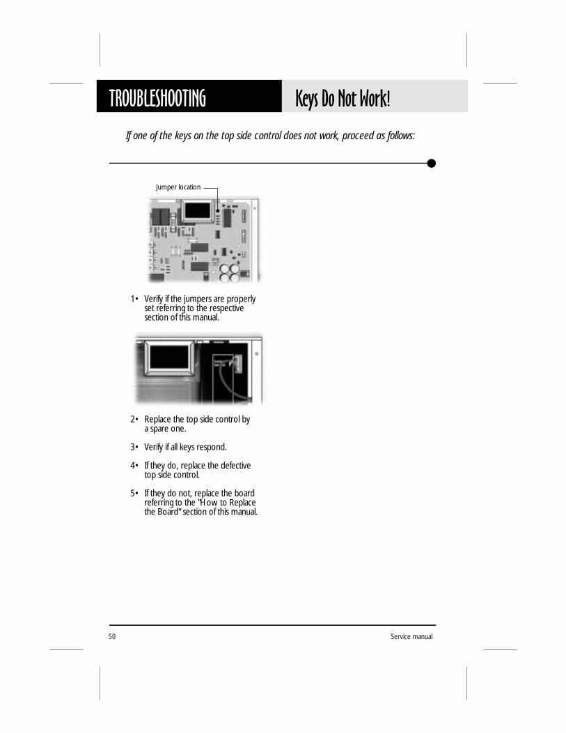
If one of the keys on the top side control does not work, proceed as follows:
1• Verify if the jumpers are properlyset referring to the respectivesection of this manual.
2• Replace the top side control bya spare one.
3• Verify if all keys respond.
4• If they do, replace the defective top side control.
5• If they do not, replace the board referring to the "How to Replace the Board" section of this manual.
Jumper location

51MSPA-1-AS
To replace the board, proceed as follows:
1• Remove your spa pack’s power box cover and disconnect the power input wires (located tothe left of the board).
3• Insert the end of a flat screwdriver into the slots at the top of the plastic cover.
4• Gently remove the plastic cover by releasing its upper part first.
2• Disconnect the top side control(s) and the temperature probe (connectors located in the upper right corner of the board).
HOW TOReplace the Board
Before you replace the board, make sure the equipment is powered off!

Service manual52
HOW TO Replace the Board
5• Disconnect the transformer. 7• Disconnect all outputs (pumps, spa light, ozonator) using a pair of pliers. Make sure not to damage the connectors!
8• Disconnect the high-limit sensor and the pressure switch.
6• Using a nut driver, remove the transformer.

53MSPA-1-AS
9• Disconnect the heater by loosen-ing the two screws P32 & P33 at the bottom of the board.
11• The board is held in place by means of six plastic standoffs (*). Release these gently using a pair of pliers.
12• Gently remove the board by releasing its left part first.
* On models manufactured before 1999, loosen the 6 screws.
10• Loosen the two triac screws while holding them with a pair of pliers to prevent damage, then remove the ground screw.
HOW TOReplace the Board

Service manual54
HOW TO Replace the Board
13• Verify if the plastic standoffs are damaged. If they are, replace them.
14• Align the new board with the plastic standoffs and snap it into place.
15• Reinstall the two triac screws while holding them with a pair of pliers to prevent damage.
Do not overtighten!
16• Reinstall the ground screw on the board.
17• Reconnect all outputs (pumps, spa light, ozonator) using a pair of pliers. Make sure not to damage the connectors! Refer to the wiring diagram affixed to the inside of your spa pack’s power box cover. This diagram always prevails over the wiring diagram at the end of this manual!
18• Reconnect the heater.
19• Reconnect the high-limit sensorand the pressure switch.
20• Reconnect the transformer.
21• Verify all connections, then reinstall the plastic cover placing its lower part first.
22• Reconnect the top side control(s) and the temperature probe.
23• Reconnect the power input wires, close the cover, powerthe equipment on and pro- ceed with a general test of your spa pack.

55MSPA-1-AS
To replace the heater, proceed as follows:
Pressureswitch
Heatingelement
nuts
High-limitsensor nuts
& plate
Heaternut
Heaternut
1• Disconnect the two wires at the top of the pressure switch, then unscrew and remove the switch.
Note: Before proceeding, make sure all power input wires are disconnected and spa valves are closed!
2• Loosen the two wing nuts that hold the plate of the high-limit sensor and remove the sensor.
HOW TOReplace the Heater
Before you replace the board, make sure the equipment is powered off!

Service manual56
HOW TO Replace the Heater
3• With the help of an open-end wrench, disconnect the heater wires (remove only the two upper nuts). Do not touch the large nuts!
4• Loosen the two heater nuts and release the heater from under the spa.
7• Gently reconnect the heater wires with an open-end wrench, while holding the lower nuts with another wrench to avoid damaging the contact pins.
8• Verify if the heater is properly connected to the board.
9• Reinstall the pressure switch and reconnect the wires (in no particular order).
5• Slide the new heater into place and fix it to the power box usingthe two nuts.
The two heater-fixing nuts must be properly tightened because they also serve as a current collector in case of heater failure.
6• Reinstall the high-limit sensor and the plate.
Tighten the two wing nuts just enough to hold the sensor plate in place.

57MSPA-1-AS
For systems manufactured from 1998 onward:
1• Turn the pump to low speed.
2• Using a flat screwdriver, increase the pressure switch setting to 4 P.S.I. or until the "FLO" error message appears on the top side control.
3• Start decreasing the setting of the pressure switch by turning the adjusting screw counter-clockwise very slowly until the "FLO" message disappears. Then, decrease by another 1/4 of a turn.
4• Run the pump at high speed for 30 seconds. You should not see an "FLO" message.
5• Turn the pump off and wait 30 seconds. You should not see an "FLC" message.
6• Run the pump at low speed for 30 seconds. You should not see an "FLO" message.
7• If you see an "FLO" or an "FLC" message, repeat the procedure above.
If you are not able to adjust the pressure switch, replace it.
For systems manufactured before 1998:
These systems are programmed with software that automatically shuts the pump off whenever an "FLO" message appears.
In this case, you have to press a key (any key) to reset the system.
The procedure for adjusting the pressure switch is the same, except that you have to decrease the setting half a turn at a time.
1• Decrease the setting by 1/2 turn.
2• Press any key and wait 5 seconds.
If the setting is too high, an "FLO" message is displayed and the pump is shut off.
3• Repeat the procedure above until the "FLO" message does not reappear.
HOW TOAdjust the Pressure Switch
To adjust the pressure switch, proceed as follows:

Service manual58
Notes:

59MSPA-1-AS
MISCELLANEOUSParts List
We recommend that field service technicians keep the items marked with an asterisk (*) in stock.
Ref. Part Number Description Retail U.S. CDN
1 530AB0061 Tail piece for 2" heater 5.39 7.331 530AB0042-P5 Gasket for 2" tail piece (package of 5) 8.00 10.882 530AB0055 Nut for 2" heater 4.90 6.67 *3 250AA0027-P25 Strain relief for light cord (package of 25") 3.50 4.763 250AA0074-P25 Strain relief for external heater's high limit sensor (pack. of 25) 3.50 4.764 EWGX178 Light cord (option LS) 7.57 10.3 *5 140AA0125-P10 Blank plate for output connector hole (package of 10) 10.89 14.826 EWGX200 J&J mini-connector for pump 1 7.26 9.886 EWGX199 J&J mini-connector for pump 2, single-speed 6.68 9.096 EWGX200 J&J mini-connector for pump 2, two-speed 7.26 9.886 EWGX204 J&J mini-connector for ozonator 5.92 8.066 EWGX203 J&J mini-connector for blower 5.92 8.066 EWGX205 J&J mini-connector for circulation pump 5.92 8.066 EWGX211 AMP connector for pump 1 7.26 9.886 EWGX212 AMP connector for pump 2, single-speed 6.68 9.096 EWGX213 AMP connector for pump 2, two-speed 7.26 9.886 EWGX206 AMP connector for ozonator 6.68 9.096 EWGX208 AMP connector for blower 6.68 9.096 EWGX207 AMP connector for circulation pump 6.68 9.096 EWGX209 AMP connector for light 5.34 7.276 EWGX188 AMP connector for external vertical heater 8.33 11.337 282FB0104-P10 Metal standoffs for triac (package of 10) 22.76 30.978 282HA0051-P25 Plastic standoffs for board (package of 25) 17.04 23.18 *9 282CA0092-P25 Nuts for transformer (package of 25) 7.57 10.3010 EWGX123-P5 Heater cable for in-line heater (package of 5) 10.47 14.2411 EWGX122 High-limit sensor for in-line heater 13.99 19.03 *11 EWGX183 High-limit sensor for external vertical heater 15.59 21.21 *12 530AA0012 In-line 5.5 kW heater 143.17 194.7912 530AB0087 5.5 kW 240 V element for in-line heater 88.20 119.99 *13 510AD0064 Pressure switch 28.42 38.67 *14 EWGX124-P5 Pressure switch cable for in-line heater (package 5) 11.80 16.06 *15 250AB0036-P25 Grommet for cable opening (package of 25) 5.45 7.4216 ACGX020 120 V transformer 45.57 62.00 *16 ACGX050 240 V transformer (option T2) 59.96 81.58 *17 430AC0054-P10 Fuses for circulation pump (package of 10) 10.69 14.55 *18 430AC0054-P10 Fuses for ozonator (package of 10) 10.69 14.55 *19 282AD0038-P25 Ground screws (package of 25) 9.86 13.4220 282AD0072-P25 Screws for heater cable (package of 25) 8.80 11.9721 430AC0069-P10 Fuses for blower (package of 10) 17.82 24.24 *22 430AC0117-P10 Fuses for light (package of 10) 11.14 15.15 *23 430AE0027-P10 Fuses for pump 1 (package of 10) 56.57 76.97 *24 282AB0128-P25 Screws for triac (package of 25) 7.68 10.4525 430AE0027-P10 Fuses for pump 2 (package of 10) 56.57 76.97 *26 EQGX155 Main board for: MSPA-2-P122-02-LS-H5.5-JJM 225.00 306.12 *26 MSPA-2-P122-01-LS-H5.5-JJM 225.00 306.12 *26 MSPA-2-P122-01-LA-H5.5-JJM 225.00 306.12 *26 MSPA-2-P122-01-LS-JJM 225.00 306.12 *26 MSPA-2-P121-01-LS-JJM 225.00 306.12 *26 MSPA-2-P122-02-LS-JJM 225.00 306.12 *

Service manual60
MISCELLANEOUS Parts List
We recommend that field service technicians keep the items marked with an asterisk (*) in stock.
Ref.: Part Number Description Retail U.S. CDN
26 EQGX196 Main board for: MSPA-1-P122-B2-01-CP2-LS-HV-JJM-NF-AX 288.97 393.15 *
26 EQGX157 Main board for: MSPA-1-P122-P222-B1-01-LS-H5.5-JJM 302.51 411.58 *
26 MSPA-1-P122-P222-B1-01-LS-H5.5-AMP 302.51 411.58 *26 EQGX151 Main board for:
MSPA-1-P112-P212-B1-01-LS-CP1-HV-JJM 311.06 423.21 *27 430AC0092-P10 Fuses for transformer (package of 10) 11.14 15.15 28 ACGX037 Plastic cover for MSPA-2 22.94 31.21 29 282AB0128-P25 Screws for cover (package of 25) 7.68 10.45 30 MQGX152 Metal cover 36.97 50.30 EWGX125 10-foot temperature probe 19.20 26.12 * EWGX245A 25-foot temperature probe 23.87 32.48 *

61MSPA-1-AS
Always refer to the wiring diagram affixed to the inside of your spa pack’s power box cover as main reference!
MISCELLANEOUSWiring Diagram
Pump 1Voltage 240 VGreen / Ground P29Black / Low Speed P19Brown / High Speed P15Blue / Neutral P22
Pump 2Voltage 240 VGreen / Ground P26Brown / Line P13Blue / Neutral P24
Jumper SettingsSee respective section
BlowerVoltage 240 VGreen / Ground P28Brown / Line P17Blue / Neutral P23
OzonatorVoltage 240 VGreen / Ground P25Brown / Line P12Blue / Neutral P21
Light ConnectorWhite / 0 VAC P9Black / 12 VAC P10
240
VAC
INP
UT
KEYP
AD W
/ DIS
PLAY
HeaterLine 1 P33Neutral P32Green / Ground Ground
INFR
ARED
SEN
SOR
KEYP
AD W
/O D
ISPL
AY
DEFE
CTIV
E OZ
ONAT
OR L
AMP
DETE
CTOR
TEM
P. PR
OBE
4937-01A

Professional Repair KitAll you need in a single case!
• Top side controls• Temperature probes• Pressure switch cables • Pressure switches• Heaters• Heater cables• Transformer• Ground lugs• Plastic standoffs• Light cables• Grommets• Connectors• Fuse kits• Screws• Etc.
Gecko's professional repair kit contains all you need to properly service and repairGecko's line of power spa packs.
Call 1.800.78.GECKOto order or for more info!


