Page 1
MS.RAJA ELGADFY/ELECTROMAGENETIC PAPER31- In Fig. 9.1, A and B are two conductors on insulating stands. Both A and B were initially
uncharged.
X Y
A B
Fig. 9.1
(a) Conductor A is given the positive charge shown on Fig. 9.1.
(i) On Fig. 9.1, mark the signs of the charges induced at end X and at end Y of conductor B.[1]
(ii) Explain how these charges are induced.
...........................................................................................................................................
............................................................................................................................. ..............
..................................................................................................................................... [3]
(iii) Explain why the charges at X and at Y are equal in magnitude.
...........................................................................................................................................
............................................................................................................................. ..............
..................................................................................................................................... [1]
(b) B is now connected to earth by a length of wire.
Explain what happens, if anything, to
(i) the charge at X,
...........................................................................................................................................
............................................................................................................................. ........ [1]
(ii) the charge at Y.
............................................................................................................................. ..............
............................................................................................................... ...................... [2]
[Total: 8]
Page 2
MS.RAJA ELGADFY/ELECTROMAGENETIC PAPER32- (a) Fig. 8.1 shows a bar magnet suspended by a spring over a coil. The coil is connected to a
sensitive centre-zero millivoltmeter.
spring
magnet
coilsensitive
centre-zeromillivoltmeter
Fig. 8.1
(i) The lower end of the magnet is pushed down into the upper end of the coil andheld at rest.
During the movement, an e.m.f. is induced in the coil. The meter shows a deflection tothe right and then returns to zero.
Explain why this e.m.f. is induced.
............................................................................................................................. ..............
...................................................................................................... ................................ [1]
(ii) State what happens to the needle of the meter when
1. the magnet is released from rest and is pulled up by the spring,
.......................................................................................... ............................................ [1]
2. the magnet continues to oscillate up and down, moving in and out of the coil witheach oscillation.
...................................................................................................... ................................ [1]
Page 3
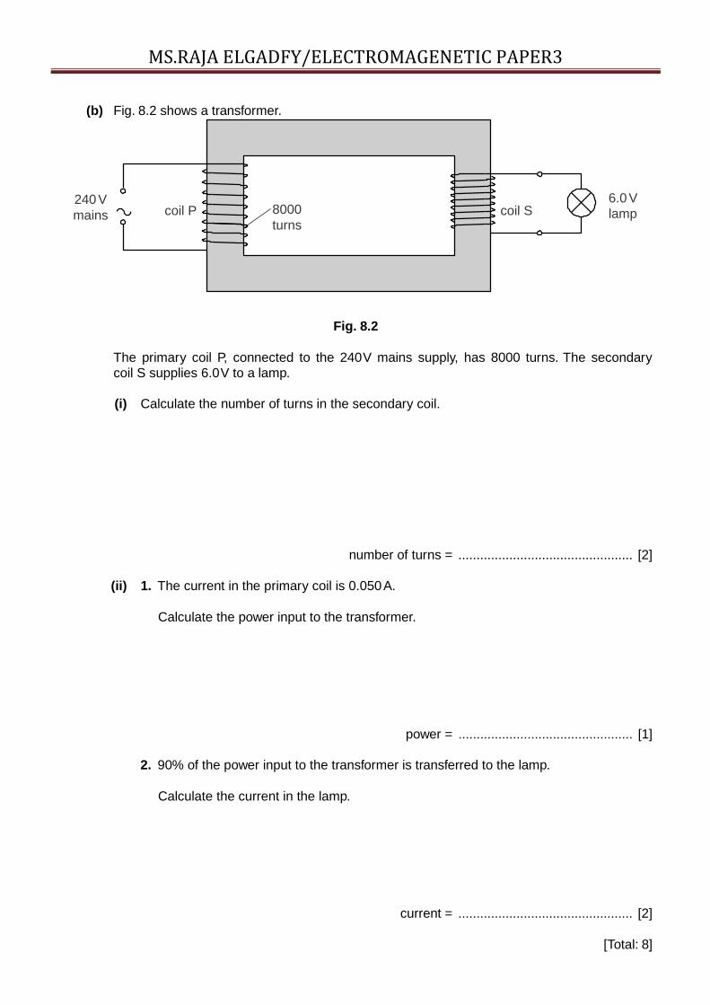
MS.RAJA ELGADFY/ELECTROMAGENETIC PAPER3(b) Fig. 8.2 shows a transformer.
240Vmains coil P 8000
turnscoil S
6.0 Vlamp
Fig. 8.2
The primary coil P, connected to the 240V mains supply, has 8000 turns. The secondarycoil S supplies 6.0V to a lamp.
(i) Calculate the number of turns in the secondary coil.
number of turns = ................................................ [2]
(ii) 1. The current in the primary coil is 0.050A.
Calculate the power input to the transformer.
power = ................................................ [1]
2. 90% of the power input to the transformer is transferred to the lamp.
Calculate the current in the lamp.
current = ................................................ [2]
[Total: 8]
Page 4
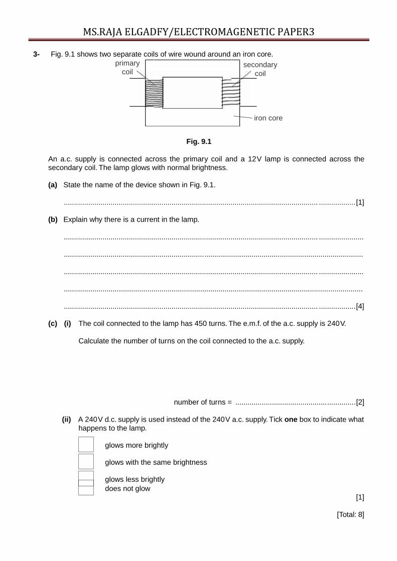
MS.RAJA ELGADFY/ELECTROMAGENETIC PAPER33- Fig. 9.1 shows two separate coils of wire wound around an iron core.
primarycoil
secondarycoil
iron core
Fig. 9.1
An a.c. supply is connected across the primary coil and a 12V lamp is connected across thesecondary coil. The lamp glows with normal brightness.
(a) State the name of the device shown in Fig. 9.1.
............................................................................................................................. ..................[1]
(b) Explain why there is a current in the lamp.
............................................................................................................................. ......................
...................................................................................................................................................
............................................................................................................................. ......................
...................................................................................................................................................
............................................................................................................................. ..................[4]
(c) (i) The coil connected to the lamp has 450 turns. The e.m.f. of the a.c. supply is 240V.
Calculate the number of turns on the coil connected to the a.c. supply.
number of turns = ...........................................................[2]
(ii) A 240V d.c. supply is used instead of the 240V a.c. supply. Tick one box to indicate whathappens to the lamp.
glows more brightly
glows with the same brightness
glows less brightlydoes not glow
[1]
[Total: 8]
Page 5
MS.RAJA ELGADFY/ELECTROMAGENETIC PAPER34- (a) Fig. 10.1 shows the cross-section of a wire carrying a current into the plane of the paper. For
Examiner’sUse
Fig. 10.1
On Fig. 10.1, sketch the magnetic field due to the current in the wire. The detail of yoursketch should suggest the variation in the strength of the field. Show the direction of thefield with arrows. [3]
(b) Fig. 10.2 shows part of a model of a d.c. motor.
B axis
A C
X
Y D
Fig. 10.2
A loop of wire ABCD is placed between the poles of a magnet. The loop is free to rotateabout the axis shown. There is a current in the loop in the direction indicated by thearrows.
(i) On Fig. 10.2, draw arrows to show the directions of the forces acting on side ABand on side CD of the loop. [1]
Page 6
MS.RAJA ELGADFY/ELECTROMAGENETIC PAPER3
Page 7
MS.RAJA ELGADFY/ELECTROMAGENETIC PAPER3(ii) With the loop in the position shown in Fig. 10.2, explain why the forces on AB and
CD cause the loop to rotate about the axis.
......................................................................................................................... .........
............................................................................................................................. .....
................................................................................................................. .................
............................................................................................................................. . [1]
(iii) The ends X and Y of the loop are connected to a battery using brushes and a split-ring commutator.
State why a split-ring commutator is used.
............................................................................................................................. .....
..................................................................................................................................
............................................................................................................................. .....
...................................................................... ........................................................ [2] [Total: 7]
5- (a) Describe an experiment that shows how a magnet can be used to produce a current ina solenoid by electromagnetic induction. Sketch and label the arrangement of apparatusyou would use.
.
.
.
.
.
.
.
.
.
.
.
.
.
.
.
.
.
.
.
.
.
.
.
.
.
.
.
.
.
.
.
.
.
.
.
.
.
.
.
.
.
.
.
.
.
.
.
.
.
.
.
.
.
.
.
Page 8
MS.RAJA ELGADFY/ELECTROMAGENETIC PAPER3...................................................................................
..........................................................................................................................................
............................................................................................................................. ........ [3]
(b) Fig. 8.1 represents a transformer with primary coil P and secondary coil S, wound on aniron core.
There is an alternating current in coil P.
ForExaminer’s
Use
iron core
P S
Fig. 8.1
(i) State what happens in the iron core as a result of the alternating current in P.
............................................................................................................................. .....
.......................................................................................... ................................... [2]
Page 9
MS.RAJA ELGADFY/ELECTROMAGENETIC PAPER3(ii) Tick the box next to the correct description of the current in S.
higher frequency a.c.
ForExaminer’s
Use
same frequency a.c.
lower frequency a.c.
rectified d.c.
constant d.c. [1]
(iii) Coil P has 50 turns of wire, an applied voltage of 12V, and a current of 0.50A.Coil S has 200 turns.
Calculate the current in S. Assume the transformer is 100% efficient.
current = .................................................. [3]
[Total: 9]
Page 10
MS.RAJA ELGADFY/ELECTROMAGENETIC PAPER36- A simple motor is made in a school laboratory. A coil of wire is mounted on an axle between the
poles of a horseshoe magnet, as illustrated in Fig. 9.1.
coil
B C
N S
A D
springy contacts (brushes)
+ –
battery
Fig. 9.1
(a) At the instant illustrated in Fig. 9.1, the coil ABCD is horizontal and the battery is connectedas shown.
(i) For this position, state the direction of the force on AB and the direction of the motion ofAB.
force on AB ........................................................................................................................
direction of motion of AB .............................................................................................. .[1]
(ii) Explain why BC does not contribute to the turning force on the coil.
...........................................................................................................................................
............................................................................................................................. ..........[1]
Page 11
MS.RAJA ELGADFY/ELECTROMAGENETIC PAPER3(b) At the instant when the coil is vertical, the springy contacts do not, in fact, make contact with
the ends of the coil.
Describe and explain what happens to the coil.
...................................................................................................................... .............................
............................................................................................................................. ......................
...................................................................................................................................................
............................................................................................................................. ..................[2]
(c) The motor in Fig. 9.1 does not rotate very quickly. The designer of a commercial motor isrequired to produce a faster-rotating motor.
Suggest one change that could be made to increase the speed of the motor.
...................................................................................................................................................
............................................................................................................................. ..................[1]
[Total: 5]
Page 12
MS.RAJA ELGADFY/ELECTROMAGENETIC PAPER37- (a) In Fig. 8.1, a magnet is moving towards one end of a solenoid connected to a sensitive centre-
zero meter. During this movement a current is induced in the solenoid.
S N
Fig. 8.1
Suggest three possible changes to the system in Fig. 8.1 that would increase the inducedcurrent.
1. ............................................................................................................................. ..................
2. ...............................................................................................................................................
3. ............................................................................................................................. ..............[3]
(b) Fig. 8.2 shows a transformer. P is the primary coil. S is the secondary coil. The coils arewound on an iron core.
P S
Fig. 8.2
P has 200 turns and S has 800 turns. The e.m.f. induced across S is 24V. The current in S is0.50A. The transformer operates with 100% efficiency.
Page 13
MS.RAJA ELGADFY/ELECTROMAGENETIC PAPER3Calculate
(i) the voltage of the supply to P,
voltage = ...........................................................[2]
(ii) the current in P.
current = ...........................................................[2]
[Total: 7]
Page 14
MS.RAJA ELGADFY/ELECTROMAGENETIC PAPER38- Fig. 9.1 is a sketch of some apparatus, found in a Science museum, which was once used to
show how electrical energy can be converted into kinetic energy.
When the switch is closed the wheel starts to turn.
switch
metalsupports
magnetNS
N
+d.c. supply
–
metalspokedwheel
S small dish ofmercury
magnetwood base
Fig. 9.1
(a) Explain why the wheel turns when the switch is closed.
............................................................................................................................. .............
..........................................................................................................................................
............................................................................................................................. .............
.................................................................................................................................... [2]
(b) On Fig. 9.1, draw an arrow to show the direction of rotation of the wheel. [1]
Page 15
MS.RAJA ELGADFY/ELECTROMAGENETIC PAPER3(c) The d.c. motor is another way to convert electrical energy into kinetic energy.
In the space below, draw a labelled diagram of a d.c. motor.
Examiner’sUse
[3]
(d) Describe how the split-ring commutator on an electric motor works.
..........................................................................................................................................
............................................................................................................................. .............
..........................................................................................................................................
............................................................................................................................. ....... [2]
[Total: 8]
Page 16
MS.RAJA ELGADFY/ELECTROMAGENETIC PAPER39 Fig. 9.1 is a block diagram of an electrical energy supply system, using the output of a coal-
fired power station.For
Examiner’sUse
Page 17
MS.RAJA ELGADFY/ELECTROMAGENETIC PAPER3powerstation
output step-uptransformer
output step-downtransformer
outputconsumer
at 1100 V at 32 000V at 240 V
9 Fig. 9.1 is a block diagram of an electricalenergy supply system, using the output of acoal- fired power station.
transmission
Fig.
9.1
(a) Suggest one possible way ofstoring surplus energy when thedemand from the consumers fallsbelow the output of the powerstation.
.....................................................................
.....................................................................
.....................................................................
...............................................................[1]
(b) State why electrical energy is transmitted athigh voltage.
.....................................................................
...............................................................[1]
(c) A transmission cable of resistanceR carries a current I. Write down aformula that gives the power lossin the cable in terms of R and I.
.....................................................................
...............................................................[1]
(d) The step-up transformer has 1200turns on the primary coil. Usingthe values in Fig. 9.1, calculate thenumber of turns on its secondarycoil. Assume that the transformerhas no energy losses.
number
of
turns
=
.
.
.
.
.
.
.
.
.
.
.
.
.
.
.
.
.
.
.
.
.
.
.
.
.
.
.
.
.
.
.
.
.
.
.
.
.
.
.
.
.
.
.
.
.
.
.
.
.
[2]
Page 18
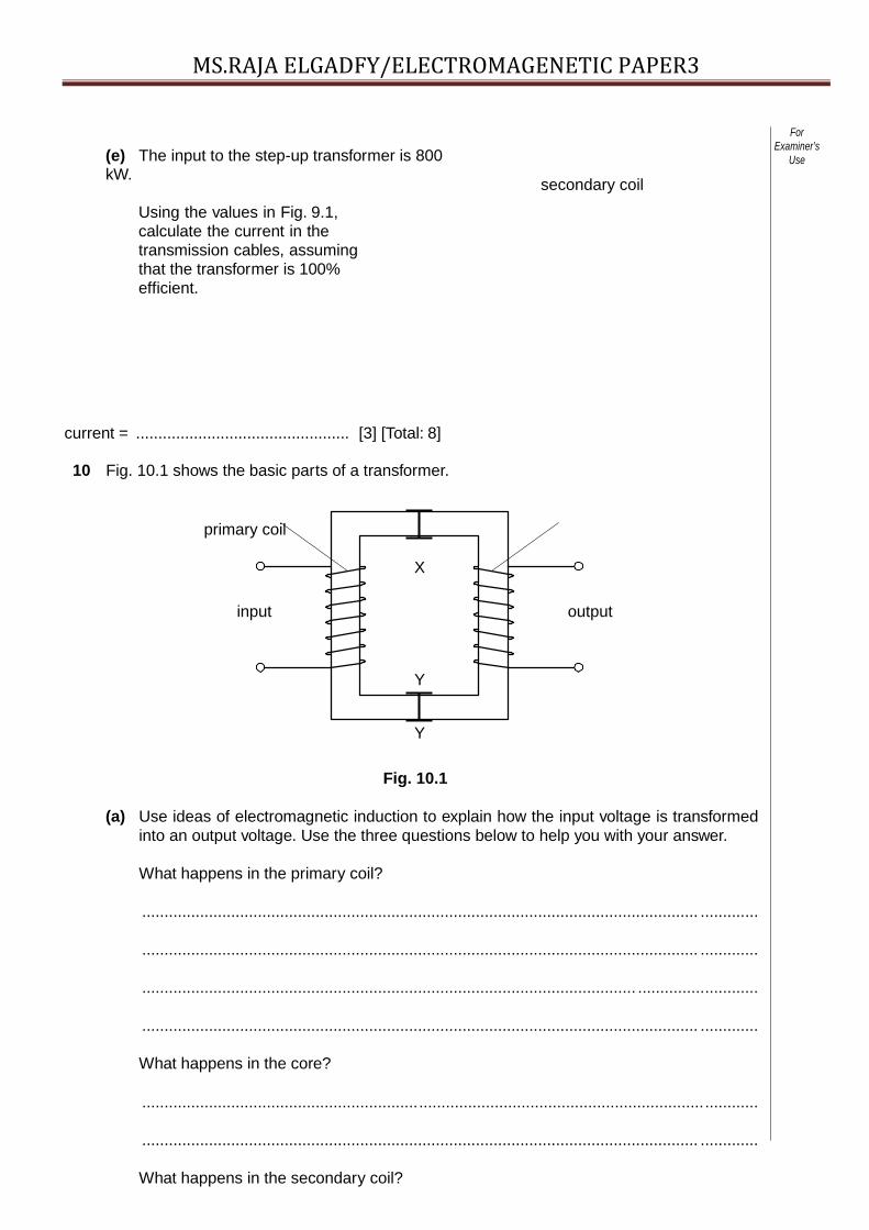
MS.RAJA ELGADFY/ELECTROMAGENETIC PAPER3(e) The input to the step-up transformer is 800kW.
Using the values in Fig. 9.1,calculate the current in thetransmission cables, assumingthat the transformer is 100%efficient.
current = ................................................ [3] [Total: 8]
10 Fig. 10.1 shows the basic parts of a transformer.
primary coil
secondary coil
ForExaminer’s
Use
X
input output
Y
Y
Fig. 10.1
(a) Use ideas of electromagnetic induction to explain how the input voltage is transformedinto an output voltage. Use the three questions below to help you with your answer.
What happens in the primary coil?
............................................................................................................................. .............
............................................................................................................................. .............
............................................................................................................... ...........................
............................................................................................................................. .............
What happens in the core?
..........................................................................................................................................
............................................................................................................................. .............
What happens in the secondary coil?
Page 19
MS.RAJA ELGADFY/ELECTROMAGENETIC PAPER3.............................................................................................................................. ............
....................................................................................................................... ...................
............................................................................................................................. ........ [5]
(b) State what is needed to make the output voltage higher than the input voltage.
.............................................................................................................................. ....... [1]
Page 20
MS.RAJA ELGADFY/ELECTROMAGENETIC PAPER3
Page 21
MS.RAJA ELGADFY/ELECTROMAGENETIC PAPER3(c) The core of this transformer splits along XX and YY. Explain why the transformer would not work if
the two halves of the core were separated by about 30 cm.
............................................................................................................................. .............
............................................................................... ...................................................... [1]
(d) A 100% efficient transformer is used to step up the voltage of a supply from 100 V to200 V. A resistor is connected to the output. The current in the primary coil is 0.4 A. Calculate
the current in the secondary coil.
current = …………………… [2]
Page 22
MS.RAJA ELGADFY/ELECTROMAGENETIC PAPER311 (a) Name the process that causes a potential difference across a solenoid due to the movement
of a nearby magnet.
................................................................................... ............................................................[1]
(b) Fig. 11.1 shows a solenoid connected to a centre-zero voltmeter, M.
A bar magnet is held with its N-pole close to one end of the solenoid.
solenoid
N
M
Fig. 11.1
(i) The magnet is pushed into the solenoid, and then brought to rest with its N-pole justinside the solenoid.
Describe the movement of the pointer of the meter M.
............................................................................................... ............................................
............................................................................................................................. ..........[2]
(ii) The magnet is now pulled to the left out of the solenoid, at a higher speed than in (i).
Compare the movement of the pointer of the meter with that seen in (i).
............................................................................................................................. ..............
...................................................................................................................................... .[2] [Total: 5]
Page 23
MS.RAJA ELGADFY/ELECTROMAGENETIC PAPER312- Fig. 10.1 shows a coil of wire rotating steadily in the magnetic field between the poles of a
permanent magnet. The current generated in the coil is to pass through resistor R.
coil
rotation ofcoil
N S
A B
C D
R
Fig. 10.1
(a) The apparatus in Fig. 10.1 is part of an a.c. generator.What is connected between the ends Aand B of the coil and the connections C and D?
............................................................................................................................. ................. [1]
(b) (i) On Fig. 10.2, sketch a graph to show the variation with time of the current through R. [1]
current
0time
Fig. 10.2
(ii) On Fig. 10.2, show the time T corresponding to one complete rotation of the coil. [1]
(iii) State two ways in which the graph would be different if the coil spins at a faster rate.
1. ............................................................................................................................. ..........
2. .................................................................................................................................. [2]
(c) Suggest what could be connected between C and R so that the current in R is always in thesame direction.
.............................................................................................................................................. [1][Total: 6]
Page 24
MS.RAJA ELGADFY/ELECTROMAGENETIC PAPER313 (a) Fig. 10.1 shows a wire PQ placed between the poles of a magnet. There is a current in
wire PQ.
ForExaminer’s
Use
Page 25
MS.RAJA ELGADFY/ELECTROMAGENETIC PAPER313 (a) Fig. 10.1 shows a wire PQ placed between the poles of a
magnet. There is a current in wire PQ.
N
PQ
S
Fig. 10.1
(i) On Fig. 10.1, sketch lines with arrows to show thedirection of the magnetic field between the poles
of the magnet.[1]
(ii) The force on PQ is into the paper.
Draw an arrow on PQ to show the direction of the current.[1]
(b) The wire PQ in Fig. 10.1 is replaced by a narrow beamof β-particles travelling from left to right.
(i) Suggest a suitable detector for the β-particles.
................................................................................................
............................. [1]
(ii) State the direction of the force on the β-particles.
................................................................................................
............................. [1]
(iii) Describe the path of the β-particles in the space betweenthe poles of the magnet.
................................................................................................
..................................
................................................................................................
............................. [1]
(iv) State what happens to the air molecules along the path ofthe β-particles.
.........................................................................................................
.
.
.
.
.
.
.
.
.
.
.
.
.
.
.
.
.
.
.
.
[
1
]
[
T
o
t
a
Page 26
MS.RAJA ELGADFY/ELECTROMAGENETIC PAPER3l
:
6
]
14- Fig. 8.1 is the plan of a small apartment that has four lamps asshown.
ForExaminer’s
Use
2 × 60Wliving room
100Wkitchen
60Wbathroom
Fig. 8.1
Power for the lamps is supplied at 200V a.c. and the lamps are all in parallel.
(a) In the space below, draw a lighting circuit diagram so that there is one switch for eachroom and one master switch that will turn off all the lamps. Label the lamps as 60W or100W.
[3]
(b) The 100W lamp is switched on. Calculate
(i) the current in the lamp,
current = ................................................ [2]
(ii) the charge passing through the lamp in one minute.
Page 27
MS.RAJA ELGADFY/ELECTROMAGENETIC PAPER3charge = ................................................ [2]
Page 28
MS.RAJA ELGADFY/ELECTROMAGENETIC PAPER3
Page 29
MS.RAJA ELGADFY/ELECTROMAGENETIC PAPER3(c) The three 60W lamps are replaced by three energy-saving ones, that give the same
light output but are rated at only 15W each.
Calculate
(i) the total reduction in power,
reduction in power = ................................................ [1]
(ii) the energy saved when the lamps are lit for one hour.
energy saved = ................................................. [2] [Total: 10]
15- Alternating current electricity is delivered at 22000V to a pair of transmissionlines.
The transmission lines carry the electricity to the customer at the receiving end, wherethe potential difference is V. This is shown in Fig. 10.1. Each transmission line has aresistance of 3Ω.
ForExaminer’s
Use
22 000V 3ΩV
3Ω
Page 30
MS.RAJA ELGADFY/ELECTROMAGENETIC PAPER3Fig. 10.1
(a) The a.c. generator actually generates at a much lower voltage than 22000V.
(i) Suggest how the voltage is increased to 22000V.
............................................................................................................................ [1]
(ii) State one advantage of delivering electrical energy at high voltage.
............................................................................................................................ [1]
(b) The power delivered by the generator is 55kW. Calculate the current in the transmissionlines.
current = ................................................ [2]
(c) Calculate the rate of loss of energy from one of the 3Ω transmission lines.
rate of energy loss = ................................................ [2]
Page 31
MS.RAJA ELGADFY/ELECTROMAGENETIC PAPER3
Page 32
MS.RAJA ELGADFY/ELECTROMAGENETIC PAPER3(d) Calculate the voltage drop across one of the transmission lines.
voltage drop = ................................................ [2]
(e) Calculate the potential difference V at the receiving end of the transmission lines.
V = ................................................ [2] [Total: 10]
16- Alternating current electricity is delivered at 22000V to a pair of transmissionlines.
The transmission lines carry the electricity to the customer at the receiving end, wherethe potential difference is V. This is shown in Fig. 10.1. Each transmission line has aresistance of 3Ω.
ForExaminer’s
Use
22 000V 3ΩV
3Ω
Fig. 10.1
(a) The a.c. generator actually generates at a much lower voltage than 22000V.
(i) Suggest how the voltage is increased to 22000V.
............................................................................................................................ [1]
(ii) State one advantage of delivering electrical energy at high voltage.
............................................................................................................................ [1]
(b) The power delivered by the generator is 55kW. Calculate the current in the transmissionlines.
Page 33
MS.RAJA ELGADFY/ELECTROMAGENETIC PAPER3current = ................................................ [2]
(c) Calculate the rate of loss of energy from one of the 3Ω transmission lines.
rate of energy loss = ................................................ [2]
Page 34
MS.RAJA ELGADFY/ELECTROMAGENETIC PAPER3
Page 35
MS.RAJA ELGADFY/ELECTROMAGENETIC PAPER3(d) Calculate the voltage drop across one of the transmission lines.
voltage drop = ................................................ [2]
(e) Calculate the potential difference V at the receiving end of the transmission lines.
V = ................................................ [2] [Total: 10]
17- A transformer is needed to step down a 240 Va.c. supply to a 12 Va.c. output.
(a) In the space below, draw a labelled diagram of a suitable transformer. [3]
(b) Explain
(i) why the transformer only works on a.c.,
............................................................................................................................. .....
........................................................................................... ...................................[1]
(ii) how the input voltage is changed to an output voltage.
............................................................................................................................. .....
.
.
.
.
.
.
.
.
.
.
.
.
.
.
.
.
.
.
.
.
.
.
.
.
.
.
.
.
.
.
.
.
.
.
.
.
.
.
.
.
.
.
.
.
.
.
.
.
.
.
.
.
.
.
.
.
.
.
.
Page 36
MS.RAJA ELGADFY/ELECTROMAGENETIC PAPER3.......................................................................
............................................................................................................................. .[2]
(c) The output current is 1.5A.
Calculate
(i) the power output,
power = ........................[1]
(ii) the energy output in 30s.
energy = ........................[1]
Page 37
MS.RAJA ELGADFY/ELECTROMAGENETIC PAPER318- Fig. 11.1 shows a flexible wire hanging between two magnetic poles. The flexible wire is
connected to a 12 V d.c. supply that is switched off. ForExaminer’s
Use
wire fixed here
+
N S 12 V d.c.–
flexible wire hangingbetween magnetic poles
wire fixed here
Fig. 11.1
(a) Explain why the wire moves when the supply is switched on.
............................................................................................................................. .............
.............................................................................................................................. ............
............................................................................................................................. ........ [2]
(b) State the direction of the deflection of the wire.
............................................................................................................................. .............
.............................................................................................................................. ....... [2]
(c) When the wire first moves, energy is changed from one form to another. State these twoforms of energy.
from ........................................................... to ............................................................ [1]
Page 38
0625/03/M/J/05© UCLES 2005 0625/03/M/J/05
MS.RAJA ELGADFY/ELECTROMAGENETIC PAPER3(d) Fig. 11.2 shows the flexible wire made into a rigid rectangular coil and mounted on an
axle.
magnetic pole
ForExaminer’s
Use
axle
magnetic pole
N Ncoil
S S
axle
Page 39
MS.RAJA ELGADFY/ELECTROMAGENETIC PAPER3
Fig. 11.2
(i) Add to the diagram an arrangement that will allow current to befed into the coil whilst allowing the coil to turn continuously. Labelthe parts you have added. [1]
(ii) Briefly explain how your arrangement works.
............................................................................................................................
.......
.............................................................................................................................. [2
19- Electromagnetic induction may be demonstrated using a magnet, asolenoid and other necessary apparatus.
(a) Explain what is meant by electromagnetic induction.
............................................................................................................................
..............
............................................................................................................................
..............
............................................................................................................................
..............
............................................................................................................................
........ [2]
(b) In the space below, draw a labelled diagram of theapparatus set up so that electromagnetic induction may be
demonstrated. [2]
Page 40
MS.RAJA ELGADFY/ELECTROMAGENETIC PAPER3
(c) Describe how you would use the apparatus to demonstrate electromagneticinduction.
............................................................................................................................
..............
............................................................................................................................
..............
............................................................................................................................
..............
............................................................................................................................
........ [2]
(d) State two ways of increasing the magnitude of the induced e.m.f. in thisexperiment.
1.......................................................................................................................................
............................................................................................................................
..............
2.......................................................................................................................................
............................................................................................................................. ....... [2]