I I I I I I I I I I I I I I I I I I I MSTI-3 SCIENCE OBJECTIVES William Jeffrey Institute for Defense Analyses 1801 N. Beauregard Street Alexandria, VA 22311-1772 James Fraser . Photon Research Associates 1911 Fort Myer Drive, Suite 408 Arlington, VA 22209 Abstract MSTI-3 is a Ballistic Missile Defense Organization (BMDO) experiment to be launched on a Pegasus booster in the winter of 1994/1995. It is the first of the MSTI satellites with the primary objectives being science-driven and is a good example of the science which can be done from a small satellite in low earth orbit. A Science Working Group has been organized to define the payload requirements and to set the observation plans. Provided here is an overview of the science objectives which include SWIR and MWIR background clutter characterization; monocular and stereo track of boosting and non- boosting targets; environmental and ecological monitoring; innovative neural network approaches to on-orbit nonuniformity focal plane array corrections; advanced filter designs; and monocular passive ranging. In addition, the utility of the data to DoD and non-DoD scientists will be highlighted and the process of obtaining the data described. If successful, MSTI-3 will demonstrate the incredible capability small satellites have for quickly and relatively inexpensively addressing some of the outstanding science issues confronting both the military and civilian remote sensing communities. L Background The Miniature Sensor Technology Integration (MSTI) program began in 1992 with the goal of producing a fast response capability and demonstrating access to space within nine months of a program's inception. MSTI-l launched in November of 1992 on a Scout vehicle with a single MWIR camera taken from the LEAP program tests. It was injected into a Maj. Garret Schneider Ballistic Missile Defense Organization The Pentagon Washington, DC 20301-7100 low-earth sun-synchronous orbit and remained on orbit for six months. The primary objective of MSTI-l was to validate the basic bus design which it successfully accomplished. MSTI-2 began in 1993 with more ambitious goals. Using a modified MSTI-l bus the satellite was launched using the last Scout vehicle in May 1994. The satellite is currently functioning in a 431 km circular orbit with a sun-synchronous geometry (approximately 6:40 equatorial crossing time). MSTI-2 contains two infrared cameras: a PtSi SWIR camera with a single spectral filter and an InSb MWIR camera with a six position filter wheeL The mission requirement for MSTI-2 is to track boosting targets below the horizon in the SWIR. A three dimensional track file is created on the ground in near real-time using an extended Kalman filter and the state vector is generated in a form compatible for transmission to an interceptor. As of this time MSTI-2 has successfully tracked the first stage of a Minuteman 3 missile. The MWIR camera was included to attempt below- the-horizon background clutter measurements as a precursor to MSTI-3 and to provide backup to the SWIR track camera. MSTI-3 is scheduled for launch in the winter of 1994/1995 using the Pegasus booster with the L-IOIL MSTI-3 is an advanced technology demonstration platform whose primary objective is to characterize the SWIR (2.7 ;.tm) and MWIR (4.3 ;.tm) background clutter to the fidelity necessary for designing sensors to perform early warning acquisition and warm body track below the horizon (BTH). It is believed that the clutter in these absorption bands {which do not see to the ground) will be relatively benign as compared to the window
Transcript
I I I I I I I I I I I I I I I I I I I
MSTI-3 SCIENCE OBJECTIVES
William Jeffrey Institute for Defense Analyses
1801 N. Beauregard Street Alexandria, VA 22311-1772
James Fraser . Photon Research Associates
1911 Fort Myer Drive, Suite 408 Arlington, VA 22209
Abstract
MSTI-3 is a Ballistic Missile Defense Organization (BMDO) experiment to be launched on a Pegasus booster in the winter of 1994/1995. It is the first of the MSTI satellites with the primary objectives being science-driven and is a good example of the science which can be done from a small satellite in low earth orbit. A Science Working Group has been organized to define the payload requirements and to set the observation plans. Provided here is an overview of the science objectives which include SWIR and MWIR background clutter characterization; monocular and stereo track of boosting and nonboosting targets; environmental and ecological monitoring; innovative neural network approaches to on-orbit nonuniformity focal plane array corrections; advanced filter designs; and monocular passive ranging. In addition, the utility of the data to DoD and non-DoD scientists will be highlighted and the process of obtaining the data described. If successful, MSTI-3 will demonstrate the incredible capability small satellites have for quickly and relatively inexpensively addressing some of the outstanding science issues confronting both the military and civilian remote sensing communities.
L Background
The Miniature Sensor Technology Integration (MSTI) program began in 1992 with the goal of producing a fast response capability and demonstrating access to space within nine months of a program's inception. MSTI-l launched in November of 1992 on a Scout vehicle with a single MWIR camera taken from the LEAP program tests. It was injected into a
low-earth sun-synchronous orbit and remained on orbit for six months. The primary objective of MSTI-l was to validate the basic bus design which it successfully accomplished.
MSTI-2 began in 1993 with more ambitious goals. Using a modified MSTI-l bus the satellite was launched using the last Scout vehicle in May 1994. The satellite is currently functioning in a 431 km circular orbit with a sun-synchronous geometry (approximately 6:40 equatorial crossing time). MSTI-2 contains two infrared cameras: a PtSi SWIR camera with a single spectral filter and an InSb MWIR camera with a six position filter wheeL The mission requirement for MSTI-2 is to track boosting targets below the horizon in the SWIR. A three dimensional track file is created on the ground in near real-time using an extended Kalman filter and the state vector is generated in a form compatible for transmission to an interceptor. As of this time MSTI-2 has successfully tracked the first stage of a Minuteman 3 missile. The MWIR camera was included to attempt belowthe-horizon background clutter measurements as a precursor to MSTI-3 and to provide backup to the SWIR track camera.
MSTI-3 is scheduled for launch in the winter of 1994/1995 using the Pegasus booster with the L-IOIL MSTI-3 is an advanced technology demonstration platform whose primary objective is to characterize the SWIR (2.7 ;.tm) and MWIR (4.3 ;.tm) background clutter to the fidelity necessary for designing sensors to perform early warning acquisition and warm body track below the horizon (BTH). It is believed that the clutter in these absorption bands {which do not see to the ground) will be relatively benign as compared to the window
bands (wavelength regions which see to the ground). The important issue is how the clutter varies as a function of waveband. A narrow band may have little clutter, but it also cuts down the signal from the target. Thus signal-tonoise will be decreased. A wider band will allow for more target signal - but may also increase the clutter, thus adversely affecting the signal-to-clutter~· What the optimal band is for a specific application is unknown.
The choice of waveband has a second important consequence. Due to the absorption in these wavelength regions, as one narrows the band, the atmosphere becomes opaque at a higher altitude. Thus a very narrow band may leave the target undetectable until it has attained an unacceptably high altitude. A broader band can see deeper into the atmosphere - but again with the potentially deleterious effect of increased clutter. Thus the background problem effectively reduces to characterizing the amount of clutter in the SWIR and MWIR as a function of height within the atmosphere.
The clutter observed is likely to be a function of latitude, season, cloud type, and solar angle. To properly characterize the effect of these parameters requires a long duration (about one year) mission so that bright clutter scenes can be assessed as either common or as statistical outliers. A short duration observation leaves this point ambiguous. MSTI-3 will be operational for a minimum of one year. Being in a sun-synchronous orbit, MSTI-3 will sample all latitudes, seasons, and most solar angles. In addition, both a visible imaging spectrometer and the NOAA A VHRR channel 3 "cloud band" are on board MSTI-3 to provide truth data as to cloud type.
The need for these data is critical. The MWIR data do not exist and there is no theoretical foundation on which to base predictions. System designers are thus forced into trying to bound the problem as opposed to knowing the answer. This approach decreases fidelity and tends to increase the cost of the surveillance system. In the SWIR we have substantial background data in one band with a relatively large footprint. There is some theoretical work which indicates that minor variations to the bandpass edges in the SWIR
2
can produce up to a factor of two lower detection threshold for the same false alarm rate.
MSTI-3 has been designed to provide these needed data. MSTI-3 contains 7 spectral filters in the SWIR and 7 spectral filters in the MWIR to sample the clutter as a function of bandwidth (and hence depth in the atmosphere).
. T-hese filters span the relevant wavelength space needed to characterize the clutter.
The spatial and temporal distribution of the clutter is also critical. MSTI-3 will provide the SWIR and MWIR clutter at a 43 m (nadir looking) footprint and 10 Hz. In addition, MSTI-3 will observe from nadir to limb to assess the angular contribution of observed clutter. These data will be taken with sensors capable of better than 3x10⁻⁸ W/cm2-sr-J.l.m (NESR). At this sensitivity we expect to characterize the clutter to better than 0.5% of the mean background level (in the MWIR) and sufficient to allow BTH tracking of warm bodies.
MSTI-3 will characterize the SWIR and MWIR BTH clutter to a level of precision which far exceeds the best of the current database and to a higher fidelity than proposed operational systems. These data will be invaluable for system designers who are trying to maximize the performance of their surveillance sensors.
Another objective of MSTI-3 is to validate the utility of small satellites for environmental monitoring. With the visible imaging spectrometer, MSTI-3 will have the same spatial resolution as Landsat-5/6 but with greater spectral resolution. Assessing the added information content of the spectral data should be useful for designing future remote sensing platforms (such as the recently announced NASA Lewis and Clark satellites).
To enhance the scientific returns from the MSTI program, BMDO established a Science Working Group (SWG). The SWG reports directly to BMDO and is tasked not only with setting the performance requirements on the bus and payload but with ensuring that the requirements are satisfied by the hardware and software. This is the first MSTI satellite where
I I I I I I I I I I I I I I I I I I I
I I I I I I I I I I I I I I I I I I I
the science community is embedded within the management structure of the program as opposed to outsiders offering suggestions. The SWG is divided into five subpanels each concentrating on a specific function. Figure 1 illustrates the organization of the SWG with the Principal Investigators for each subpanel listed.
!._ Science W:o!ldng Gr"!l..P G. Schneider (BMDO) - Chairman
I W. Jeffrey (IDA) • Chief Scientist I J. Fr.ner (PRA)- Chief Engineer
P. Albright, IDA I A. Ratkowski, PUGPO M. Briggs, lSI
A. Ratkowski, ~~ I ~ Gobel, ANSER I
~ ~-no-WtiV-' e~Co-nc-ep-ts"l J. Brunner, WRI i J. Fr.ner, PRA
1 J. Hood, ANSER 1'---____ ---' Fig. 1. Organizational chart for MSTI-3 SWG
The backgrounds subpanel is responsible for setting the performance requirements for characterizing the SWIR and MWIR BTH and limb spatial and temporal clutter. The tracking subpanel is responsible for insuring that the data needed for developing a real-time state vector are obtained and that the ability to develop stereo tracks with MSTI-2 is exploited. The dual use subpanel is tasked with insuring that the civilian and non-BMDO defense communities are aware of MSTI-3's capabilities and develop observations of use to those communities. The iImovative concepts subpanel explores new technologies (hardware and software) which may be exploitable by MSTI The objective is to validate high risk concepts which have potentially high payoffs if successful. The calibration subpanel exists to insure that the requirements of all other panels are being met and that the spacecraft system is calibrated to the level necessary to allow for the unambiguous interpretation of the data.
II. Sensor Capabilities
The MSTI-3 payload consists of three cameras: a SWIR imager, MWIR imager, and a visible imaging spectrometer. In addition a star tracker is mounted directly to the payload which together with a GPS receiver greatly improves
the ephemeris and thus pointing knowledge over previous MSTIs.
Figure 21 represents the payload for MSTI-3. A two-axis gimbal mirror initially directs the light into the optical train. The telescope consists of a two element reflective F/3.6 system with a 10.5 cm aperture. The light -isilietHplit off into three paths depending upon the wavelength. The visible goes off to the imaging spectrometer, and the SWIR and MWIR pass through spectral filters and into InSb detectors. In addition, an onboard blackbody calibration source is located within the field-of-regard of the sensors. This blackbody source will operate at two stable temperatures (between 220 - 250 K) to emulate the earth's anticipated radiance for the on-orbit characterization of the sensors.
TEtESCQPE VIS CAlERA
VIS LENS CELL I r GIMBALlED MIRROR
/ GIMBALLAUI«lH J.OCI( ~ BEAIISI'UTTER S
~IRRcrms-----+--~~·.I--~
~IICAIIERA ---ti---l4~+t,lq~+
~IR LEIISCELL --+---J
MWIR LENS CELL
MWIR RLJ'BI$
MWIRCAMERA
OPTCALBEI«:H ~
3
STIlRllIACKfR
Fig. 2. Schematic of MSTI-3 Payload.
The sensitivity of the imagers must be sufficient to track an aerotherrnally heated booster after its engine has burned out. For example, a warm booster hardbody may have a signature of 50 W/sr in the MWIR at a 1000 km slant range, thus requiring an NEFD of better than 5xIO-16 W/cm2 for a S/N=IO. In addition, the spatial footprint has to be less than any proposed operational system2 to avoid extrapolating the spatial clutter data. This constraint drove us to require a footprint of less than 50 m (nadir-looking). Understanding the MWIR clutter as a function of wavelength is critical to optimally trade-off target strength with background clutter. This last requirement
drove the need for multiple passband filters spanning the appropriate wavelength regime. Table 1 and Figure 3 provide the specifications for the MWIR filters. In addition, the stringent requirements on the filter slope and out-of-band rejection are listed. In Figure 3 the short wavelength side of all the filters is shown by one line (since the specifications are identical). The long waJielengtn..-side for the- six background filters are then shown by individual curves.
Characterizing the SWIR BTH clutter is a second requirement for MSTI-3. The primary source of clutter in the SWIR is believed to arise from solar scattering off of high altitude clouds3. Since the prevalence and cloud types vary as a function of latitude and season4,
a long duration mission (greater than one year) with an orbital inclination of 600 or greater is necessary. MSTI-3 is thus designed to be in a sun-synchronous orbit and has a -30' expected lifetime of one year (the lifetime is driven by the amount of propellant necessary to achieve its
4
final orbit). Since clutter mitigation is a critical component of the mission, there was a desire to have the S WIR footprint identical to the MWIR footprint so that spectral rejection techniques could be applied. Thus both imagers have identical spatial characteristics. As with the MWIR, characterizing the SWIR clutter as a function of wavelength results in very stringent spooifications. Table 2 and Figure 4 illustrates the filter requirements for the SWIR. Note that the last two filters have identical bandpasses. This is to validate a new filter technology (rugate) which is described in the next section.
MSTl-3 SWlR FILTER SPECS 0.5 ,...........::D::.:ED:;;IC:;:..:A~T E::.D .::.BA::.C".;.::G:...:,RO:.:UTND:.,:F.,::I L T.::::E:...;RSr---,
5 0.4
gs ~ 0.3
Ci: 0.2 to: ~ 0.1
u:: J \\"-\ \ 0L-~~----~~~~~ 2.6 2.7 2.8 2.9 3
WAVELENGTH (JLm)
Out-Of-Band ReJection:
Red: 1x10⁻⁵
Blue: 5x10⁻⁶
Fig. 4. SWIR Filter Specifications
1..<0% 2.98 2.93 2.89 2.86 2.83 N/A N/A
In addition to infrared imaging, there is a goal of evaluating the utility of moderate spatial and spectral resolution data in the visible. Spatial resolution on the scale of Landsat (approximately 30 m) is desired for direct comparison but with higher spectral resolution to assess the utility of the added infonnation content. Combining this goal with the desire to validate new and innovative
I I I I I I I I I I I I I I I I I I I
I I I I I I I I I I I I I I I I I I I
concepts on the MSTI platform led us to choose a wedge filter design where the spectral interference filter is bonded directly to the focal plane surface. This innovative design reduces the number of optical elements needed, is robust to vibration, and takes up less volume and weight. Figure 5 illustrates the basic properties of the camera.
t 7.01 km
+
Visible Focal Plane Clear (20 %)
600 nm
858 nm
.....-8.42 km ...
Satellite Motion ..
Fig. 5. Visible imaging spectrometer
To meet the above requirements, the MSTI·3 payload consists of three imagers: two InSb 256x256 focal planes covering the SWIR and MWIR and a 768x494 silicon visible detector with a linear wedge filter. These instruments were chosen to answer specific questions of relevance to space surveillance nusslons. The following table provides predicted sensor performance for the imagers5:
SWIR MWIR VIS NEIBTH (W/cm2) 5.5xlO-17 6.1xlO-I7 8.4xlO-18
The IR cameras are manufactured by Amber engineering and are derivatives of their commercial Radiance camera design. The spectral filters are manufactured by Deposition Sciences, Inc. and Rockwell, Inc. and the payload pointing system, thermal control, and visible camera is designed and assembled by Science Applications International Corporation (SAI-C • La Jolla).
III. Science Plans
a) Background Clutter Characterization As stated above, the background clutter
characterization in the SWIR and MWIR constitute the primary missions for MSTI·3. Understanding the clutter as a function of wavelength, season, cloud type, and solar angle is critical for establishing the statistical data base necessary for future space surveillance and tracking systems. The highest priority observations with MSTI·3 consist of:
• Solar scattering (diffuse & specular) • Large region surveys • 3·D structure • Earth limb • Temporal variations • Standard reference scenes • Aurora (BTH & A TH) • Jetstream & strat·warming • High altitude airglow
Each of these observations will be conducted several times over the satellite lifetime to build up a statistically meaningful database6 .
Since atmospheric absorption varies spectrally, assessing the clutter as a function of waveband is equivalent to characterizing clutter as a function of altitude. The broader spectral filters will see to the ground (or close to it) and the radiation transmitted through the narrower filters will be absorbed at higher altitudes (some substantially above cloud deck). It is assumed that the narrower bandpasses (high altitude) will contain less clutter; but it is an assumption and will be validated with the data from MSTI-3. Figures 6 and 7 depict the atmospheric attenuation as a function of wavelength with the spectral filters overlaid (note that all the filters have identical blue sides but slightly varying red sides). The two dashed curves represent optical depths of unity and two as seen from space looking nadir. That is, the optical depth of unity
corresponds to that altitude where approximately 36% of the light penetrates (the rest is absorbed or scattered). An optical depth of two corresponds to where approximately 10% of the light is transmitted.
As can be seen from the figures given below, each filter corresponds to sampling a slightly different-' altitude. -By cembining the data from several filters, one can begin to "peel the onion" and model the altitude dependence of clutter.
MSTI-3 SWIR ATMOS. SOUNDING ~{.l,)IR LOOI-{IN3 C 97~ LB BTAN=-::
0.5 r--,-----.-r-r---r"-~___, 15
""-1:=1 0.4 I ""-
o I \ _ 0.3 I / "- \ ~ .1 "-~ 0.2 V 1:;2
~ ! 0: I- 0,1
>-10 ~
=i c o m '5C'
5~
OL....L.~--~-'-~...:.....~-....:),::::..JO
2.7 2.8 2.9 3
WAVELENGTH (Ilm)
Fig. 6. SWIR Atmospheric Sounding
MSTI-3 MWIR. ATMOS. SOUNDING 50 NADIR LOOKING (1976 US STAND) 50
§ <of Uj ~ 30 :;;;: (f) z « 0: I-0: UJ 1-, 10
o I 4.2 4.25 4.3 4.35 4.4 4.45
WAVELENG-~H (11m)
Fig. 7. MWIR Atmospheric Sounding
40
Since the cloud structure is so critical to understanding the clutter (especially in the SWIR) significant truth data is necessary to eliminate ambiguities in the analysis. MSTI-3 is obtaining the truth data in many ways. First
6
the MWIR contains the A VHRR Channel 3 spectral band which will be used to image clouds and will provide a baseline for comparison with the much larger field of view data obtained by NOAA and DMSP. MSTI-3 also contains the visible imaging spectrometer which 'will provide simultaneous imagery of clouds with the IR imagers. In addition to the on-boafd truth data aRd the data from NOAA and DMSP, MSTI is coordinating to obtain in situ data from aircraft flights and ground calibration sites operated by NASA, DoD, and the USDA (Forestry Service).
The following picture (Figure 8) represents a typical cluttered scene in the MWIR against which a dim target may need to be tracked. The data come from MSTI-2 looking towards the earth limb. The dark regions in the foreground represent clouds which are colder than the hard earth and thus show up as black The structure at the limb itself appears to be real and is currently being assessed. A space-based tracking system must have the capability to maintain a target's position in the presence of substantial background structure. Gathering the data so that clutter rejection algorithms can be developed is the thrust of MSTI-3.
Fig. 8. MSTI-2 Image of Earth Limb in MWIR
b) Tracking The objective of the MSTI tracking
experiment is to develop and validate the tools needed to generate a three-dimensional state vector accurate enough to be used as a real-time update for interceptors such as Navy LEAP.
I I I I I I I I I I I I I I I I I I
, I I I I I I I I I I I I I I I I I I
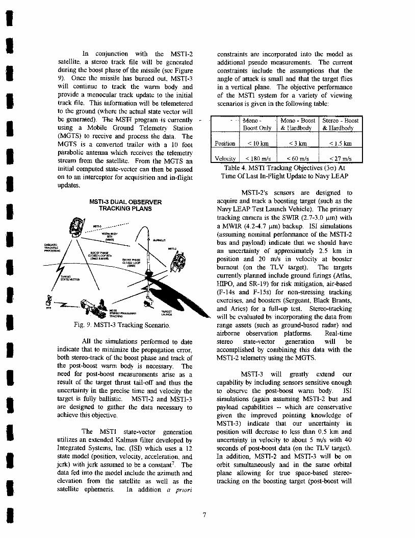
In conjunction with the MSTI-2 satellite, a stereo track file will be generated during the boost phase of the missile (see Figure 9). Once the missile has burned out, MSTI-3 will continue to track the warm body and provide a monocular track update to the initial track file. This information will be telemetered to the ground (where the actual state vector will be generated). T-he MSH pr-ogram ·is currently -using a Mobile Ground Telemetry Station (MGTS) to receive and process the data. The MGTS is a converted trailer with a 10 foot parabolic antenna which receives the telemetry stream from the satellite. From the MGTS an initial computed state-vector can then be passed on to an interceptor for acquisition and in-flight updates.
MSTI-3 DUAL OBSERVER TRACKING PLANS
hi .~ ___ ,_-.-.. -... ~~
Fig. 9. MSTI-3 Tracking Scenario.
All the simulations performed to date indicate that to minimize the propagation error, both stereo-track of the boost phase and track of the post-boost warm body is necessary. The need for post-boost measurements arise as a result of the target thrust tail-off and thus the uncertainty in the precise time and velocity the target is fully ballistic. MSTI-2 and MSTI-3 are designed to gather the data necessary to achieve this objective.
The MST! state-vector generation utilizes an extended Kalman filter developed by Integrated Systems, Inc. (lSI) which uses a 12 state model (position, velocity, acceleration, and jerk) with jerk assumed to be a constant7. The data fed into the model include the azimuth and elevation from the satellite as well as the satellite ephemeris. In addition a priori
7
constraints are incorporated into the model as additional pseudo measurements. The current constraints include the assumptions that the angle of attack is small and that the target flies in a vertical plane. The objective performance of the MSTI system for a variety of viewing scenarios is given in the following table:
Table 4. MSTI Tracking Objectives (30-) At Time Of Last In-Flight Update to Navy LEAP
MSTI-2's sensors are designed to acquire and track a boosting target (such as the Navy LEAP Test Lannch Vehicle). The primary tracking camera is the SWIR (2.7-3.0 j.1m) with a MWIR (4.2-4.7 j.1m) backup. lSI simulations (assuming nominal performance of the MSTI-2 bus and payload) indicate that we should have an uncertainty of approximately 2.5 km in position and 20 m1s in velocity at booster burnout (on the 1L V target). The targets currently planned include ground firings (Atlas, HIPO, and SR-19) for risk mitigation, air-based (F-14s and F-15s) for non-stressing tracking exercises, and boosters (Sergeant, Black Brants, and Aries) for a full-up test. Stereo-tracking will be evaluated by incorporating the data from range assets (such as ground-based radar) and airborne observation platforms. Real-time stereo state-vector generation will be accomplished by combining this data with the MSTI-2 telemetry using the MGTS.
MSTI-3 will greatly extend our capability by including sensors sensitive enough to observe the post-boost warm body. lSI simulations (again assuming MSTI-2 bus and payload capabilities -- which are conservative given the improved pointing knowledge of MSTI-3) indicate that our uncertainty in position will decrease to less than 0.5 km and uncertainty in velocity to about 5 m1s with 40 seconds of post-boost data (on the 1L V target). In addition, MSTI-2 and MSTI-3 will be on orbit simultaneously and in the same orbital plane allowing for true space-based stereotracking on the boosting target (post -boost will
be observable only by MSTI-3 due to radiometric sensitivity).
By the conclusion of MSTI-3 we will have the phenomenology data and tracking experience needed to help optimize future spacebased surveillance systems. The knowledge gained will impact sensor design parameters (e.g., wavebands, .footprints, and· temporal sampling) as well as algorithms to be employed (methods and inclusion of a priori constraints). From the tracking simulations performed to date, MSTI-2 and MSTI-3 will provide us with the necessary experience to provide an interceptor (such as the Navy LEAP) with the initial track and an in-flight update with an error basket small enough to be within the divert capability of the interceptor.
c) Environmental Monitoring A third objective of the MSTI-3
program is to exploit dual use applications of the satellite for civilian remote sensing. Several communities have expressed an interest in the data and are working within the Science Working Group to define specific observations that would be of interest. Given the MSTI-3 revisit times and narrow fields of view, most of the observations center on proof-of-principle as opposed to routine monitoring of the environment. In addition, given the demise of Landsat 6 and the failure of the Landsat 5 data recorder, a number of communities who were interested in the Landsat data are scrambling to attain data in other ways. The following table highlights some of the similarities and differences between the Landsat 6 system and the MSTI-3 spectral bands:
10.4-12.5 120 185 N/A N/A * MST[·3 Visible spectral bands would be created by sunnning the appropriate spectrometer bins to match the Landsat-6 bands.
Table 5. Comparison ofLandsat-6 and MSTI-3.
8
The following sections describe dual-use observations currently planned for MSTI-3.
1) AGRHYMET Project The AGRHYMET Regional Center is a
joint US-French funded effort to assist the third world in famine prediction and resource allocation. Within the U.S., the Agency for International Development (AID) is the focal point. A research center has been opened in Niamey, Niger which is in the Sahel region of Africa (just south of the Sahara). This region is affiictedwith droughts and poor land resource management. Figure 10 outlines the geometry and basic research interests.
Monitor Concentration of Ground Water Our! ng Rainy and Dry S.a.ono
Compare Desertification WEartler Surveys
Map Land Un of Romote Roglono by Nomadic Trlb ..
Fig. 10. Location of AGRHYMET and Interests
The AGRHYMET Project is primarily interested in the water distribution in the Sahel especially during the wet and dry seasons. Given the fact that MSTI-3 is a starer as opposed to a scanning system, our total field-ofview is rather small. Thus MSTI-3 is not capable of producing large surveys of land areas. Instead we can concentrate in depth over a welldefined area. As a proof-of-concept, the AGRHYMET Project has defined a region in Niger about 100 krn x 100 krn in which they desire visible data. The objectives are:
• Determine Areas Under Cultivation • Identify Village Location and Size • Identify Water Body Locations for Cattle • Map Forested Areas • Map Degraded Areas • Identify Cultivated Areas on Poor Ground • Locate Wetlands for Biodiversity • Monitor Agricultural Practices
The data collected will be correlated with much older data to assess the extent of change in the region. If the data prove useful, then the same techniques can be applied to data from future remote sensing platforms (such as Landsat-7).
, I I I I I I I I
I I I I I I I
I I I I I I I I I I I' I I I I I I I I
2) US Fish & Wildlife In recent years the level of
sophistication of using infrared and visible data for monitoring the nation's biodiversity patterns has steadily increased. Most of this work has been done by airborne assets exploring very small geographical regions and ecosystems8,9.
Given the availability of space-based data to a wide civilian '. community, the application of remotely monitoring large geographic regions is becoming feasible.
MSTI-3 hopes to help the civilian remote sensing community in exploiting spacebased assets to probe the environment. In one specific case, we will be working with the US Fish & Wildlife service to ascertain the landscape and biodiversity patterns along the central Platte River valleylO and to monitor the protected wildlife reserves in the Congo. The former work will be funded by a grant from the Nature Conservancy.
The goal of the work is to monitor the biodiversity and to define a generic metric based upon classical Shannon information theory. Utilizing the MSTI-3 visible imaging spectral data provides the investigators with the spatial and spectral resolution necessary to test their ideas and to begin the ambitious task of defining an appropriate metric.
3) USDA Forestry Service The USDA Forestry Service is
responsible for the care and well-being of the nation's forests. Included in this charter is the monitoring of forest destruction due to fires, disease, and pestilence. MSTI-3 offers unique capabilities to monitor these effects.
The MWIR imaging capability of MSTI-3 should be able to observe the onset of fires in high-risk or remote areas when they are only tens of square meters in size. This is a substantial improvement over existing capabilities which offer kilometer size footprints.
Along different lines, the MSTI-3 visible imaging spectrometer covers the 700 nm photosynthetic stress line. Biomass which photosynthesize tends to have a large reflectance increase near 700 nm. From previous studies, it is apparent that the precise wavelength where
9
the reflectivity increases can shift towards the blue by more than 20 nm depending upon the stress of the biomassll . This type of spectral shift is within the detection capability of MSTI-3. In addition, we hope to correlate the visible results with slight temperature differences observed in the MWIR due to changing amounts of plant transpiration. Thus we will be looking
. at -regions of forests which are stressed due to drought and pestilence and comparing the results with healthy forests. H remote sensing can be applied to this problem, then the Forestry Service will be able to marshal its resources in a more efficient and timely manner to eradicate the problem.
4) Volcano Monitoring The following MWIR picture (Figure
11) is from MSTI-2 and is of the Llaima volcano in Chile which erupted in late May 1994. The caldera is believed to be just outside the field-ofview in the upper right corner. Most of the signal is thought to be generated from hot gases and warm surface features (possibly lava flow and lahars).
Fig. 11. Image of Llaima Volcano From MSTI-2
The Llaima volcano is located in a very remote site and is virtually inaccessible from the ground. In addition, it is located on a glacial plateau and during the eruption, significant amounts of ice melted causing floods downstream and endangering small local villages 12. The Llaima volcano illustrates an ideal case for remote surveillance to assess the
extent and likely ramifications of a natural disaster,
In addition to mapping out the damage from erupting volcanoes, a substantial amount of research is being done on monitoring active and semi-dormant volcanic regions. This research is centered around looking for observables which correlate with levcis'Of volcanic activity. Little predictive capability exists (with the exception of increased seismic activity) mostly due to the lack of phenomenological data.
MSTI -3 plans to continue monitoring natural disasters such as volcanoes. The combination of highly spatially resolved MWIR and visible imaging provides a unique capability to assess volcanic activity around the world,
d) Innovative Concepts
One of the objectives of the MSTI program is to use the platform as a testbed for innovative concepts which otherwise might not get the opportunity to be validated. These concepts consist of both hardware and software. The goal is to attempt technically high risk but potentially high payoff concepts - which if successful might significantly impact the cost or robustness of future operational systems.
MSTI -3 has embedded several innovative concepts within the payload and operations. These include hardware (wedge filter and rugate filters) and software (neural network nonuniforrnity correction and monocular passive ranging). This section will describe each of these innovative concepts and how they are being implemented on MSTI-3.
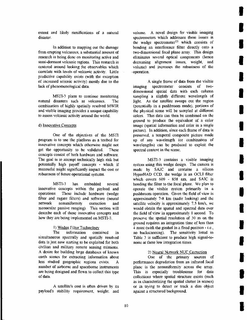
I) Wedge Filter Technology The information contained in
simultaneous spectrally and spatially resolved data is just now starting to be exploited for both civilian and military remote sensing missions. A desire for building large databases of known earth scenes for extracting information about less studied geographic regions exists. A number of airborne and spaceborne instruments are being designed and flown to collect this type of data.
A satellite's cost is often driven by its payload's stability requirement, weight, and
10
volume. A novel design for visible imaging spectrometers which addresses these issues is the wedge spectrometer13 which consists of bonding an interference filter directly onto a two-dimensional focal plane array. This design eliminates several optical components (hence decreasing alignment issues, weight, and volume) and increases the robustness of the
.. operation.
A single frame of data from the visible imaging spectrometer consists of twodimensional spatial data with each column sampling' a slightly different wavelength of light. As the satellite sweeps out the region (potentially in a pushbroom mode), portions of the physical scene will be sampled at different colors. This data can then be combined on the ground to produce the equivalent of a color image (spatial information and color in a single picture). In addition, since each frame of data is preserved, a temporal composite picture made up of any wavelength (or combination of wavelengths) can be produced to exploit the spectral content in the scene.
MSTI-3 contains a visible imaging system using this wedge design. The camera is made by SAIC and contains a silicon HyperHAD CCD, the wedge is an OCLI filter which covers 600 - 858 nm, and SAIC is bonding the filter to the focal plane. We plan to operate the visible system primarily in a pushbroom operation. Given the field of view is approximately 7-8 kill (nadir looking) and the satellite velocity is approximately 7.5 k:m/s, we would obtain the spatial and spectral data over the field of view in approximately I second. To preserve the spatial resolution of 30 m on the ground requires an integration time of less than 4 msec (with the gimbal in a fixed position - i.e., no backscanning). The sensitivity listed in Table 3 is sufficient to produce high signal-tonoise at these low integration times.
2) Neural Network NUC Correction One of the primary sources of
performance degradation from an infrared focal plane is the nonuniforrnity across the array. This is especially troublesome for data collections where spatial structure exists (such as in characterizing the spatial clutter in scenes) or in trying to detect or track a dim object against a structured background.
I I I I I I I I I I I I I I I I I I I
I I I I I I I I I I I I I I I I I I I
As part of their work on air vehicle detection, the Naval Research Laboratory (NRL) has been working on a neural network nonuniformity correction (NUC) applicable to focal plane arrays 1 4. This process should remove both high and low spatial frequencies across the array due to slight variations in pixelto-pixel responsivity.
The work performed by NRL to date has successfully demonstrated the concept on IR imagers in a laboratory environment. We plan to push the applicability directly to a spacebased sensor by using MSTI-3. No dedicated hardware is being used; instead the data will be collected and processed on the ground. To collect the data we will be executing a slow random motion of the focal planes around a structured scene in a circular/helical pattern with a maximum radius of about 10 pixels. The structured scene is necessary to train the NUC algorithm to properly interpret information at varying spatial frequencies.
If successful, the neural network NUC algorithm offers the promise of substantially improved focal plane performance through implementation of a rather simple software scheme. The two basic questions to be answered by the MSTI-3 data are: 1) How effective is the algorithm in a "real world" scenario? and 2) How long are the derived NUC coefficients applicable (i.e., how often does the NUC need to be performed)?
3) Rugate Filters As part of the BMDO survivability
program a new generation of spectral filters have been produced. These filters employ rugate technology15,16 which is capable of producing filters with extremely sharp edges. In addition to the sharp edges one can notch out small regions of the spectral bandpass to eliminate individual spectral lines.
To test this new technology, MSTI-3 is flying two rugate filters: one in the SWIR and the other in the MWIR. The SWIR filter matches the cold filter within the dewar but with a narrow spectral notch removed. The" A VHRR Channel 3" filter in the MWIR is also made out of the rugate technology.
11
In addition to validating the ability of rugate technology to meet stringent filter specifications, we will be able to make a direct comparison of the degradation between a rugate filter and conventional filter using the two wide SWIR bands. Anyon-orbit degradation will be apparent from a change in optical throughput of the filters.
phase information in space-based acquisition and tracking (from platforms like Brilliant Eyes, ALARM, and DSP). Traditional tracking from space uses stereo viewing by two or more satellites. This is inefficient because of: (1) the need for multiple satellites to view the same geographic location increases the constellation size; (2) the need to associate tracks between (multi-target) focal planes with different views in a cluttered environment; and (3) the need for either satellite-to-satellite communication and on-orbit trajectory estimation or a real-time communication link from each sensor to a central ground computing node.
Monocular passive ranging from an observer to a target embedded in the atmosphere exploits the (usually negative) effect of atmospheric attenuation of the signaP 7 . By a judicious choice of wavebands one is able to determine the range (and hence altitude) of the target - passively and with only a single observer. Combining the range with angleangle information provides the threedimensional instantaneous position of the target. This result is relatively insensitive to assumed atmospheric models or precise source spectral content.
MSTI-3 carries the appropriate spectral filters to validate monocular passive ranging. In a series of observations with both boosting and non-boosting targets, data will be taken in a number of MWIR bands. Once the data is on the ground, it will be processed to back out the altitude of the target and compared with radar truth data. If successful, monocular passive ranging offers the possibility of either greatly increasing the accuracy of a state vector or decreasing the constellation size needed for a specified track accuracy requirement.
e. Calibration & Characterization
Proper calibration and characterization of the MSTI-3 satellite is considered critical to attaining the science objectives. The stated perfonnance requirements dictate the characterization preClSlOn and accuracy needed 1 8. To attain the required level offidelity for the -backgrounds clutter measurement we require:
• Fit 0 t fB dR' I er u-o-an e ectlOn: Mode Red Side Blue Side SWIR 5xlO-5 5xl0-6
Sampled at 1/5 Pixel • Highest Temporal Frequency: 176 Hz
There are a number of steps which we are taking to insure that the characterization perfonned satisfies the requirements listed. These steps include: I) Using MSTI-2 to validate bus performance, 2) MSTI-3 component level testing by SAlC, 3) Payload level testing by Utah State University Space Dynamics Laboratory (USUlSDL), 4) Spacecraft level testing at Phillips Laboratory, and 5) On-orbit characterization.
Since the MSTI-2 bus is nearly identical to the MSTI-3 bus, we can exploit the fact that MSTI-2 is on orbit to assess its performance for MSTI-3. Specifically we will be characterizing the jitter coupled to the bus from the cryocoolers, reaction wheels, and memory module. By staring at a fixed point and turning the equipment on and off, we should be able to isolate the jitter contribution from each component. If any of the contributions exceeds the requirements, then a fix for MSTI-3 would be necessary.
In addition to the jitter, we can exploit MSTI-2 to validate our assumptions about component degradation and radiation sensitivity. MSTI-2 is utilizing observations of the full moon to estimate optics and filter degradation over time. By looking at the moon
12
in the same phase, we can estimate changes to the modulation transfer function as well as the optical throughput. We are also monitoring any single event upsets (SEUs) to insure that the electronic components on MSTI-3 will be properly hardened. To date, no SEUs have been observed on MSTI-2.
SAlC is responsible for the design, construction, and integration of the MSTI-3 payload. They are thus responsible for insuring that each component meets design specifications (e.g., optical throughput and readout noise level). After the assembly of the payload, SAlC will perfonn basic functionality and sensitivity tests19 to insure that no problems exist. In addition, SAlC is responsible for the final radiometric calibration of the visible imaging spectrometer and gimbal characterization.
USU/SDL is responsible for the absolute radiometric characterization and calibration of the SWIR and MWIR imagers20. Specific tests include filter out-of-band measurements, spectral response, off-axis response, and absolute responsivity as a function of integration times, gains, and flux level. These measurements will be done at the operational temperatures anticipated on orbit.
A full system end-to-end evaluation will be done at Phillips Laboratory at Edwards Air Force Base21 after integration of the payload with the bus. These tests will include vibration, thennal and vacuum, EM!, RFI, and a final software and payload perfonnance validation. Upon successful completion of these series of tests the spacecraft will be sent to Vandenburg Air Force Base for mating with the Pegasus launch vehicle.
Once on orbit a series of characterization tests are planned. Initially the spacecraft will go through a complete shakedown process where perfonnance of the sensors, tracker, and software will be confirmed. Prior to and after every observation a calibration procedure will be followed which includes looking towards cold space for determining dark current and looking at the calibration plate at two temperatures which are representative of the mean earth temperature in the 4.3 /-Lm absorption band (the actual temperatures for the
I I I I I I I I I I I I I I I I I I I
I I I I I I I I I I I I I I I I I I I
calibration plate will depend upon the primary filter chosen for the observation). Then periodically (approximately once per month) a set of observations will be performed to assess any degradation to the optics or filters. These tests will look at reference objects (celestial sources) to assess optical throughput off-axis scatter, and modulation transfer function.
IV. Observation Planning and Data Archival
MSTI-3's 1ll1SS10n planning is intentionally flexible. The intent is to maintain an open and fluid process so as to optimize the observations based upon data already collected and to allow as many diverse communities access to the satellite as possible. Thus anyone with a need for the type of data which MSTI-3 can supply is welcome to submit a proposaL
Once a proposal is formulated, the investigator presents it to the Science Working Group which evaluates the technical merits of the idea. If the SWG determines the proposal to be technically sound and consistent with the capabilities of the satellite, then the idea will be written up as an observation plan and sent to the operations team for execution.
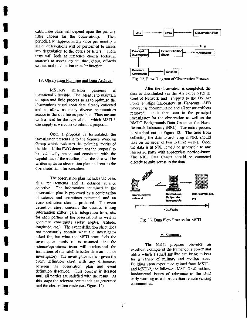
The observation plan includes the basic data requirements and a detailed science objective. The information contained in the observation plan is processed by a combination of science and operations personnel and an event definition sheet is produced. The event definition sheet contains the detailed timing information (filter, gain, integration time, etc. for each portion of the observation) as well as geometry constraints (solar angles, latitude, longitude, etc.). The event definition sheet does not necessarily contain what the investigator asked for, but what the MSTI team feels the investigator needs (it is assumed that the science/operations team will understand the limitations of the satellite better than an outside investigator). The investigator is then given the event definition sheet with any differences between the observation plan and event definition described. This process is iterated until all parties are satisfied with the result At this stage the relevant commands are generated and the observation made (see Figure 12).
I ~~ I ~ I SatPJlite I Fig. 12. Flow Diagram of Observation Process
After the observation is completed, the data is downlinked via the Air Force Satellite Control Network and shipped to the US Air Force Phillips Laboratory at Hanscom, AFB where it is decommutated and all sensor artifacts removed. It is then sent to the principal investigator for the observation as well as the BMDO Backgrounds Data Center at the Naval Research Laboratory (NRL). The entire process is sketched out in Figure 13. The time from collecting the data to archiving at NRL should take on the order of two to three weeks. Once the data is at NRL it will be accessible to any interested party with appropriate need-to-know. The NRL Data Center should be contacted directly to gain access to the data.
Fig. 13. Data Flow Process for MSTI
V. Sumrrnuy
The MSTI program provides an excellent exantple of the tremendous power and utility which a small satellite can bring to bear for a variety of military and civilian users. Building upon experience gained from MSTI-l and MSTI-2, the follow-on MSTI-3 will address fundamental issues of relevance to the DoD early warning as well as civilian remote sensing communities.
With the primary mission being the characterization of the SWIR and MWIR BTH and limb clutter, MSTI-3 will resolve issues which have been debated and yet remained unresolved for more than twenty years. A number of much more elaborate and expensive mission have preceded MSTI-3 to answer this issue - but all have failed either due to technical misfortune or budgetary constraints.
In addition to the backgrounds clutter characterization, MSTI-3 will work in tandem with MSTI-2 to explore the efficacy of spacebased stereo tracking of boosting and nonboosting targets. Utilizing the MGTS, the MSTI program will be able to push the "Commander-in-the-field" to the next step and allow users real-time access to satellite imagery.
The MSTI program is taking its dual use applicability very seriously. There are a number of civilian communities who are somewhat stymied in their research efforts due to the lack of high quality remote sensing data. MSTI-3 is working closely with a number of these communities to help rectifY the situation and prove out the value of access to space-based data. The specific areas we are pursuing include assistance to the Agency for International Development in their famine prediction and relief work; the U.S. Fish & Wildlife Service in mapping out biodiversity patterns; the U.S. Forestry Service in fire monitoring and biomass stress; and in volcanic activity monitoring.
Consonant with the MSTI objective of being an advanced technology demonstration platform, several innovative concepts will be tried on MSTI-3. These concepts include hardware (wedge spectrometer and rugate filters) as well as software (neural net nonuniformity corrections and monocular passive ranging). If these concepts prove viable, they can be used to reduce the cost or increase the robustness and fidelity of future surveillance systems.
The MSTI-3 payload has a tremendous capability for advancing our understanding of SWIR and MWIR background clutter as well as improving our state-vector generation capability and providing important data to the civilian remote sensing community. To provide data which is meaningful to these disparate
14
communities requires comprehensive calibration and characterization of the entire MSTI-3 satellite. A several step process has been outlined which will provide the level of fidelity necessary to perform the science missions described in this paper.
The MSTI program is pushing the . ·utility of small satellites within the DoD as well
as the civilian remote sensing community. There are a number of applications for MSTI-3 in which the Science Working Group are pursuing and will be demonstrating the efficacy of collecting this type of data from a low earth orbit satellite. The advantages of using a LEO small satellite are enormous: typically lower cost and less time between conception and launch. In the current budgetary climate, these two advantages will often be the difference between a funded hardware program and a paper study. The MSTI program is demonstrating that one does not have to forfeit scientific merit to achieve low cost and fast response.
VI. Acknowledgments
The authors would like to thank Dr. Ben McGlamery and Brad Barnicoat of Photon Research Associates for providing the processed images of the volcano and earth limb, lB. Wilson and Jim Patterson of ANSER Corporation for the picture of the MSTI-3 tracking scenario, and Rich Gobel of ANSER Corporation and Maile Smith of IDA for critically reviewing this document.
VII. References
1. "MSTI-3 Payload Module Assembly", Science Application International Corporation, January 12,1994.
2. Coleman, G., Lt., 1993, "Brilliant Eyes TMD Plume and Background Phenomenology Needs and Issues", Brief given 28 October.
3. Dickinson, R.P. 1991, "Earth Background Imagery at 2.7 Ilm and 4.3 Ilm Observed by Delta Star", Aerospace Report TOR-0091(6069-01)-5.
I I I I I I I I I I I I I I I I I I
I I I I I I I I I I I I I I I I I I I
4. Wylie, D.P. and W.P. Menzel, 1989, "Two Years of Cloud Cover Statistics Using VAS", Journal of Climate, 2,380.
5. "MSTI-3 Payload Module Assembly - InProcess Review", Science Application International Corporation, January 25, 1994.
7. Briggs, M., 1994, "Target State Vector Determination for MSTI-2 and -3", Presented to MSTI SWG Tracking Panel Meeting #2, 16 February.
8. Sidle, lG., et aJ. 1993, "Aerial Thermal Infrared Imaging of Sandhill Cranes on the Platte River, Nebraska", Remote Sensing Environment, 43, 333.
9. Cocks, T.D. and AA Green, 1986, "Airborne Spectroradiometry: The Application of AIS Data to Detecting Subtle MineraI Absorption Features", Proceedings of the Second Airborne Imaging Spectrometer Data Analysis Workshop, JPL Publication 86-35, 52.
10. Sidle, 1G., D.E. Jelinski, 1 Wu, P.1 Currier, and A.A Steuter. 1994, "Analysis of Landscape and Biodiversity Patterns in the Central Platte River Valley, Nebraska Using MSTI and Landsat Data", Proposal to the Nature Conservancy.
11. Collins, W., et aJ., 1983, Economic Geology, 78, 728.
13. Elerding, G.T., lG. Thunen, and L.M. Woody, 1991, "Wedge Imaging Spectrometer: Application to Drug and Pollution Law Enforcement", SPIE Vol. 1479 Surveillance Technologies, 380.
14. Scribner, D.A, K.A. Sarkady, M.R Kruer, l T. Caulfield, lD. Hunt, M. Colbert, and M. Descour, 1993, "Adaptive Retina-Like Preprocessing for Imaging Detector Arrays",
15
IEEE International Conference on Neural Nets, March.
15. Johnson, W.E., c.L. Strecker, and lE. Davison, 1983, "Preparation and Characterization of a Silicon-Gernlanium Rugate Filter", Proceedings of the Fifth DoD Conference on Laser Vulnerability, Effects and Hardening, JTCG/AS-82-D-003 (y), Vol. V, 33.
16. Kogler, K., 1985, "Rugate Filter Studies", AFWAL-TR-85-4071.
17. Jeffrey, W., lS. Draper, and R Gobel, 1994, "Monocular Passive Ranging", IRIS Targets, Backgrounds, and Discrimination Meeting, to be published in proceedings.
18. Gobel, R, A. Ratkowski, and W. Jeffrey, 1994, "Miniature Sensor Technology Integration-III Calibration Test Plan", ANSER Corporation, 31 July.
19. Hiddelston, R, 1994, Science Application International Corporation, private communication.
20. Jensen, G. and A Thurgood, 1994, "Test Procedures for MSTI-III Calibration at SDLIUSU", 7 July.
21. Hurtz, R, and K. Singler, 1994, Phillips Laboratory, private communication.