32
MT-CNC Auxiliary Function Output V16 DOK-MT*CNC-AUX*FUN*V16-ANW1-EN-P Description mannesmann Rexroth engineering Indramat 273075
| Date post: | 07-Mar-2018 |
| Category: |
Documents |
| Upload: | vuongnguyet |
| View: | 216 times |
| Download: | 1 times |

MT-CNCAuxiliary Function Output
V16
DOK-MT*CNC-AUX*FUN*V16-ANW1-EN-P
Description
mannesmannRexroth
engineering
Indramat273075

Auxiliary Function Output
About this document DOK-MT*CNC-AUX*FUN*V16-ANW1-EN-E1,44 � 06.97
Auxiliary Function Output
Description
DOK-MT*CNC-AUX*FUN*V16-ANW1-EN-E1,44
� Mappe 5 Reg 8
� M508163E.pdf
� Drawing no.: 109-0768-4163-00/E
This document describes the extended functionality of the AuxiliaryFunction Output.
This electronic document is based on the hardcopy document withdocument desig.: DOK-MT*CNC-AUX*FUN*V16-ANW1-EN-P
Revision Date Remarks
109-0768-4163-00 11/95 New issue
DOK-MT*CNC-AUX*FUN*V16-ANW1-EN-E1,44 06/97 1st E-Dok
� INDRAMAT GmbH, 1996
Copying this document, and giving it to others and the use orcommunication of the contents thereof without express authority, areforbidden. Offenders are liable for the payment of damages. All rights arereserved in the event of the grant of a patent or the registration of a utilitymodel or design (DIN 34-1).
The electronic documentation (E-doc) may be copied as often as neededif such are to be used by the customer for the purpose intended.
INDRAMAT GmbH � Bgm.-Dr.-Nebel-Str. 2 � D-97816 Lohr a. Main
Telefon +49 (0) 9352/40-0 � Tx 689421 � Fax +49 (0) 9352/40-4885
Abt. ENC (GL)
Title
Kind of dokument
Docu-Type
Internel filing remarks
Purpose of this document
Reference
Copyright
Published by

Auxiliary Function Output
DOK-MT*CNC-AUX*FUN*V16-ANW1-EN-E1,44 � 06.97 Table of Contents I
Table of Contents
1 Introduction................................................................................................................. .1-1
2 M, Q, S, T and E Functions .........................................................................................2-12.1 Basics...................................................................................................................................................2-1
2.2 M Functions..........................................................................................................................................2-1
2.3 Q Functions ..........................................................................................................................................2-3
2.4 S Functions ..........................................................................................................................................2-3
2.5 T Function ............................................................................................................................................2-4
2.6 E Function ............................................................................................................................................2-4
3 Machine Parameters....................................................................................................3-13.1 Basics...................................................................................................................................................3-1
3.2 Global M Function Mode ......................................................................................................................3-1
3.3 Global Q Function Mode ......................................................................................................................3-2
3.4 S Function Mode ..................................................................................................................................3-2
3.5 T/E Function Mode...............................................................................................................................3-2
3.6 Deviating M and Q Functions ...............................................................................................................3-2
3.7 M Function Groups...............................................................................................................................3-3
4 Output and Acknowledgement Behaviour.................................................................4-14.1 Normal Auxiliary Functions...................................................................................................................4-1
Output and Acknowledgement 'at the Beginning of a Movement’ .................................................4-1
Output and Acknowledgement 'at the End of the Movement'’.......................................................4-1
Output 'at the Beginning of the Movement' and Acknowledgement'at the End of the Movement' .........................................................................................................4-2
4.2 Swift Auxiliary Functions.......................................................................................................................4-3
General..........................................................................................................................................4-3
Swift M and Q Function Output .....................................................................................................4-3
Inquiring Swift M and Q Functions.................................................................................................4-4
Swift S, T and E Function Output ..................................................................................................4-5
No Auxiliary Function Output.........................................................................................................4-5
5 PLC User Programming ..............................................................................................5-15.1 Inquiring a Change in the Auxiliary Functions (with Group Specification)............................................5-1
5.2 Direct Inquiry of an Auxiliary Function (Specifying the Number) ..........................................................5-2
5.3 Direct Acknowledgement of an Auxiliary Function (Specifying a Number) ..........................................5-3
5.4 Reading an Auxiliary Function Number................................................................................................5-4
5.5 Acknowledging an Auxiliary Function (Specifying the Group) ..............................................................5-7
5.6 Sequence of the M00, M01, M02, and M30 Function Output...............................................................5-8

Auxiliary Function Output
II Table of Contents DOK-MT*CNC-AUX*FUN*V16-ANW1-EN-E1,44 � 06.97
M Functions M00 and M01............................................................................................................5-8
M Functions M02 and M30............................................................................................................5-8
6 Index ........................................................................................................................ .....6-1
7 Table of Figure .............................................................................................................7 -1

Auxiliary Function Output
DOK-MT*CNC-AUX*FUN*V16-ANW1-EN-E1,44 � 06.97 Introduction 1-1
1 IntroductionThe primary and secondary times of a machine can only be reduced by aparallel or a swifter machining sequence, including all auxiliary and utilityfunctions. Due to the specified number of axes and the arrangement oftools and workpieces, parallel machining is not possible for the majority ofmachine tools. There is a large number of obstacles to increasing thespeed of machining; the mechanical part, in particular, frequently meetsits limits (machine structure, bearings, tools, ...).
Thus, time-optimized output and processing of auxiliary functions is ofsupreme importance to increasing the productivity of a manufacturingplant. This is even more important with machining centres that are ca-pable of high-speed (cost-intensive) machining.
Reducing machining time
Time-optimized processing ofauxiliary functions

Auxiliary Function Output
DOK-MT*CNC-AUX*FUN*V16-ANW1-EN-E1,44 � 06.97 M, Q, S, T and E Functions 2-1
2 M, Q, S, T and E Functions
2.1 Basics
The following functions are available in the MT-CNC:
� Three-digit M functions (M0 through M999)
� Four-digit Q functions (Q0 through Q9999)
� S functions with up to five integer and up to two fractional part digits(S0.00 through S99999.99; the NC only transfers the integers to thePLC)
� Seven-digit T functions (T0 through T9999999)
� One-digit E functions (E0 through E9)
Within an NC block, the user may program a maximum of six auxiliaryfunctions. In each block, a maximum of
� 6 M functions,
� 1 Q function,
� 1 S1 function,
� 1 S2 function,
� 1 S3 function,
� 1 T function and
� 1 E function
are permitted.
.
.N0423 M103 S1 200 M204 S2 400 M319 S3 0 ;activating spindles 1 and 2 andposition tool spindle 3
.
.
2.2 M Functions
‘M functions ’ can be used for activating various machine functions.Some M functions have a fixed functionality assigned:
� M0 unconditional stop� M1 conditional stop� M2 end of program with reset� M30 end of program with reset� Mj03spindle j clockwise j � {‘‘, ‘1’, ‘2’, ‘3’}� Mj04spindle j counter-clockwise� Mj05spindle j halt� Mj13spindle j clockwise and coolant/lubricant ON� Mj14spindle j counter-clockwise and coolant/lubricant ON� Mj19positioning spindle j� Mj40automatic gear changes for spindle j� Mj41gear level 1 for spindle j� Mj42gear level 2 for spindle j� Mj43gear level 3 for spindle j� Mj44gear level 4 for spindle j
Available auxiliary functions
Example
Task

Auxiliary Function Output
2-2 M, Q, S, T and E Functions DOK-MT*CNC-AUX*FUN*V16-ANW1-EN-E1,44 � 06.97
Mxxx xxx � {0 through 999}
M=Variable
Variable=M (group no.) group no.. � {1 through 16}
M functions may be grouped. Groups 1 through 4 and 11 through 13 aregroups that have the program and spindle control functions and the gearchanging functions invariably allocated. The other group can have up to12 M functions allocated by the machine manufacturer.
Group Name M function
1 program control commands M0, M1, M2, M30
2 control commands spindle 1 M3, M4, M5, M13, M14, M19,M103, M104, M105, M113,M114
3 control commands spindle 2 M203, M204, M205, M213,M214
4 control commands spindle 3 M303, M304, M305, M313,M314
5 group 5 (definable in the process para-meters)
.
.
.
10 group 10 (definable in the process para-meters)
11 changing gears for spindle 1 M40, M41, M42, M43, M44,M140, M141, M142, M143,M144
12 changing gears for spindle 2 M240, M241, M242, M243,M244
13 changing gears for spindle 3 M340, M341, M342, M343,M344
14 group 14 (definable in the process para-meters)
15 group 15 (definable in the process para-meters)
16 modal M functions all M functions that do not be-long to groups 1 through 15
The M functions for changing gears (‘Mj40’ through ‘Mj44’) may be usedfor other purposes if a multi-stage gearbox for spindle 'j' has not beenentered in the parameters. However, the M functions ‘Mj40’ through ‘Mj44’always belong to the M function groups 11 through 13.
The machine manufacturer defines the functionality of the other auxiliaryfunctions.
The machine manufacturer defines output time and acknowledgementbehaviour of the individual M functions.
� An NC block may contain up to six M functions.
� Out of the function groups 1 though 16, the user may only programone M command in each NC block.
� If the machine manufacturer has selected 'acknowledgement later' fora given M function, the user may append a 'Q' (for Quick) to the name(example: MQ80) to output this function as a swift auxiliary function(without interruption of the movement).
� The processing state of a swift M function can be interrogated when a'W' (for Wait) is added to the name.
� The same spindle index 'j' that has been stored in the axis parametersof the spindle designation must be programmed for the spindle-related
Syntax
Groups
Setting parameter values
Programming

Auxiliary Function Output
DOK-MT*CNC-AUX*FUN*V16-ANW1-EN-E1,44 � 06.97 M, Q, S, T and E Functions 2-3
M functions ‘Mj03’, ‘Mj04’, ‘Mj05’, ‘Mj13’, ‘Mj14’, ‘Mj19’ and ‘Mj40’through ‘Mj44’. This is particularly important for the first spindle that iseither designated as spindle 'S' (and must then be triggered with the Mfunctions ‘M3’, ‘M4’, ‘M5’, ‘M13’, ‘M14’, ‘M19’, ‘M40’ through ‘M44’), oras spindle 'S1' (that must be triggered with the M functions ‘M103’,‘M104’, ‘M105’, ‘M113’, ‘M114’, ‘M119’, ‘M140’ through ‘M144’).
� Within a block, the NC always outputs the program control commands‘M0’, ‘M1’, ‘M2’ and ‘M30’ at the end of the movement, and waits forthem to be acknowledged. The time of the output and the acknow-ledgement behaviour of these M functions cannot be altered.
� Provided that a multi-stage gearbox exists, the NC outputs the gearswitching functions ‘Mj40’ through ‘Mj44’ at the beginning of a block.The NC then waits until the related M function has been acknowledgedbefore it continues program execution .
� The machine manufacturer may define output time and acknow-ledgement behaviour of the ‘Mj03’, ‘Mj04’, ‘Mj05’, ‘Mj13’, ‘Mj14’ and‘Mj19’ spindle control commands according to the requirements. Withthe exception of ‘Mj19’, the spindle control commands may be se-lected as swift M functions and, with an inserted 'Q', asynchronously toNC block processing be accelerated or decelerated to the requiredspeed. Irrespective of the acknowledgement of the auxiliary functionand whether or not the spindle has attained the programmed speed,the NC transitions to the next block.
2.3 Q Functions
The machine manufacturer defines the functionality of the ‘Q functions ’.
Qxxxx xxxx � {0 through 9999}
Q=Variable
Variable= Q
The machine manufacturer defines output time and acknowledgementbehaviour of the individual Q functions.
� An NC block may contain a maximum of one Q function.
� If the machine manufacturer has selected 'acknowledgement later' fora given Q function, the user may add a 'Q' (for Quick) to the name(example: QQ80) to output this function as a swift auxiliary function(without interruption of the movement).
� The processing state of a swift Q function can be interrogated when a'W' (for Wait) is added to the name.
2.4 S Functions
The 'S functions ' ‘S’ and/or ‘S1’, ‘S2’ and ‘S3’ are used in the NC pro-gram for specifying
� spindle speed [rpm],� spindle position [°],� cutting speed [m/min] or [inch/min] and� speed limitation [rpm] and� grinding wheel peripheral speed [m/s] or [feet/s]
for the first, second and third spindle of a process.
Sxxxxx.xx, Sj xxxxx.xx or Sj=xxxxx.xx xxxxx.xx � {0.00 through 99999.99}
S=Variable or Sj= Variable j � {1, 2, 3}
integer part digits fractional part digits
Peculiarities
Task
Syntax
Setting parameter values
Programming
Task
Syntax

Auxiliary Function Output
2-4 M, Q, S, T and E Functions DOK-MT*CNC-AUX*FUN*V16-ANW1-EN-E1,44 � 06.97
spindle speed 5 2
spindle position 3 2
constant cutting speed 5 2
speed limitation 5 2
grinding wheel pe-ripheral speed
3 2
The machine manufacturer defines output time and acknowledgementbehaviour of the individual S functions.
� The same spindle index 'j' that has been stored in the axis parametersof the spindle designation must be programmed for the S functions.
� An NC block may contain up to three S functions. The S functionsmust have different axis indices.
� The NC always starts the execution of the motion of NC-controlledspindles at the beginning of the feed movement, irrespective of theselected output and acknowledgement behaviour of the related S or Mfunction. If the spindle movement has been initiated by a normal Mfunction, the NC waits at the end of the feed movement until the ex-pected spindle value has reached the programmed final value.
� The NC continues program execution without this check if the spindlemovement has been caused by a swift M function (MQj03, MQj04,MQj05, MQj13, MQj14; j�{1, 2, 3}).
� Using the parameters, the machine manufacturer can output the Sfunctions to the PLC for both, PLC-controlled spindles and NC-con-trolled spindles.
2.5 T Function
The 'T function ' specifies the tool and/or location number of the next toolthat is to be changed in.
Txxxxxxx x � {0 through 9999999}
T=Variable
Variable=T
The machine manufacturer defines output time and acknowledgementbehaviour of the T/E functions.
An NC block may contain a maximum of one T function.
Provided that tool management has not been selected, the user mayemploy the T functions like any other auxiliary function for implementingtasks.
2.6 E Function
The 'E function ' is used for selecting the current tool edge.
Ex x � {0 through 9}
E=Variable
Variable=E
The machine manufacturer defines output time and acknowledgementbehaviour of the T/E functions.
An NC block may contain a maximum of one E function.
Provided that tool management has not been selected, the user mayemploy the E functions like any other auxiliary function for implementingtasks.
Setting parameter values
Programming
Peculiarities
Task
Syntax
Setting parameter value
Programming
Peculiarities
Task
Syntax
Setting parameter values
Programming
Peculiarities

Auxiliary Function Output
DOK-MT*CNC-AUX*FUN*V16-ANW1-EN-E1,44 � 06.97 Machine Parameters 3-1
3 Machine Parameters
3.1 Basics
The parameters below are used for defining the output and acknowledge-ment behaviour of the M, Q, S, T, and E functions. The output behaviourcan be specified as 'at the beginning of the movement', 'at the end of themovement', or 'no output'. The acknowledgement behaviour can be 'at thebeginning of the movement', 'at the end of the movement', or 'later'.
If the machine manufacturer defines the output behaviour as 'at the begin-ning of the movement' or 'at the end of the movement', the NC transfers theauxiliary function concerned as a normal auxiliary function to the PLC and, ifnecessary, waits for the acknowledgement at the beginning or at the end ofthe movement. If the machine manufacturer defines the output behaviouras 'no output', the auxiliary function concerned will not reach the PLC.
If the acknowledgement behaviour is defined as 'at the beginning of the mo-vement' or 'at the end of the movement', the NC waits at the beginning or atthe end of the movement for the acknowledgement of the functions conce-rned. If, in contrast, the machine manufacturer defines theacknowledgement behaviour as 'later', the NC transfers the auxiliaryfunction as a swift auxiliary function to the PLC and continues programexecution without interruption (provided that the user has programmed thisfeature by a 'Q' in the function designation). If the user does not insert a 'Q'in the function designation, the NC only continues program execution at theend of the movement after the PLC has acknowledged the output auxiliaryfunction.
3.2 Global M Function Mode
Global M function mode
A00.087
System parameter
Output behaviour: at the end, at the beginning, no outputAcknowledgement behaviour: at the end, at the beginning, later
Output behaviour: at the endAcknowledgement behaviour: at the end
-
The 'Global M function mode ' parameter defines the output behaviourand acknowledgement behaviour of all M functions across the processes.
Instruction :
� Up to 40 M functions with an output and acknowledgement behaviourthat differs from the global M function mode may be defined for eachprocess.
� The M functions ‘M0’, ‘M01’, ‘M02’, ‘M30’ cannot be entered. The NC al-ways outputs these functions at the end and waits until the PLC has ack-nowledged them before it continues with executing the next block.
� The NC always outputs the gear shift functions ‘Mj40’ through ‘Mj44’ (j �{‘‘, ‘1’, ‘2’, ‘3’}) at the beginning of a block. If a multi-stage gearbox exists,the NC waits at the end of the movement, and continues program exe-cution only after the output M function has been acknowledged. Indepen-dently of the selected behaviour, the NC always responds like this if theM functions ‘Mj40’ through ‘Mj44’ are used for selecting gears. The NConly considers the entered output and acknowledgement behaviour of
Options
Output behaviour
Acknowledgement behaviour
Name
Number
Parameter
Value range
Default value
Unit
Purpose

Auxiliary Function Output
3-2 Machine Parameters DOK-MT*CNC-AUX*FUN*V16-ANW1-EN-E1,44 � 06.97
the M functions ‘Mj40’ through ‘Mj44’ if these functions are not used forchanging gears.
3.3 Global Q Function Mode
Global Q function mode
A00.088
System parameter
Output behaviour: at the end, at the beginning, no outputAcknowledgement behaviour: at the end, at the beginning, later
Output behaviour: at the endAcknowledgement behaviour: at the end
-
The 'Global Q function mode ' parameter defines the output behaviourand acknowledgement behaviour of all Q functions across the processes.
Hinweis : Up to 40 Q functions with an output and acknowledgement be-haviour that differs from the global Q function mode may be de-fined for each process.
3.4 S Function Mode
S function mode
A00.089
System parameter
Output behaviour: at the end, at the beginning, no outputAcknowledgement behaviour: at the end, at the beginning, later
Output behaviour: no outputAcknowledgement behaviour: later
-
The 'S function mode ' parameter defines the output behaviour and ack-nowledgement behaviour of all S functions across the processes.
3.5 T/E Function Mode
T/E function mode
A00.090
System parameter
Output behaviour: at the end, at the beginning, no outputAcknowledgement behaviour: at the end, at the beginning, later
Output behaviour: no outputAcknowledgement behaviour: later
-
The 'T/E function mode ' parameter defines the output behaviour and ack-nowledgement behaviour of all T and E functions across the processes.
3.6 Deviating M and Q Functions
� Deviating M functions� Deviating Q functions
Bxx.046Bxx.047
Name
Number
Parameter
Value range
Default value
Unit
Purpose
Name
Number
Parameter
Value range
Default value
Unit
Purpose
Name
Number
Parameter
Value range
Default value
Unit
Purpose
Name
Number
Auxiliary Function Output
DOK-MT*CNC-AUX*FUN*V16-ANW1-EN-E1,44 � 06.97 Machine Parameters 3-3
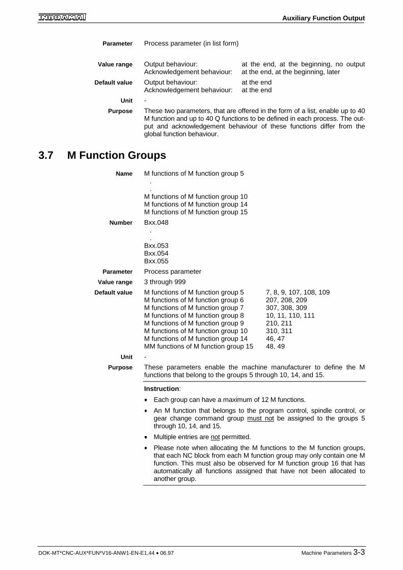
Process parameter (in list form)
Output behaviour: at the end, at the beginning, no outputAcknowledgement behaviour: at the end, at the beginning, later
Output behaviour: at the endAcknowledgement behaviour: at the end
-
These two parameters, that are offered in the form of a list, enable up to 40M function and up to 40 Q functions to be defined in each process. The out-put and acknowledgement behaviour of these functions differ from theglobal function behaviour.
3.7 M Function Groups
M functions of M function group 5 . .M functions of M function group 10M functions of M function group 14M functions of M function group 15
Bxx.048 . .Bxx.053Bxx.054Bxx.055
Process parameter
3 through 999
M functions of M function group 5 7, 8, 9, 107, 108, 109M functions of M function group 6 207, 208, 209M functions of M function group 7 307, 308, 309M functions of M function group 8 10, 11, 110, 111M functions of M function group 9 210, 211M functions of M function group 10 310, 311M functions of M function group 14 46, 47MM functions of M function group 15 48, 49
-
These parameters enable the machine manufacturer to define the Mfunctions that belong to the groups 5 through 10, 14, and 15.
Instruction :
� Each group can have a maximum of 12 M functions.
� An M function that belongs to the program control, spindle control, orgear change command group must not be assigned to the groups 5through 10, 14, and 15.
� Multiple entries are not permitted.
� Please note when allocating the M functions to the M function groups,that each NC block from each M function group may only contain one Mfunction. This must also be observed for M function group 16 that hasautomatically all functions assigned that have not been allocated toanother group.
Parameter
Value range
Default value
Unit
Purpose
Name
Number
Parameter
Value range
Default value
Unit
Purpose

Auxiliary Function Output
DOK-MT*CNC-AUX*FUN*V16-ANW1-EN-E1,44 � 06.97 Output and Acknowledgement Behaviour 4-1
4 Output and Acknowledgement Behaviour
4.1 Normal Auxiliary Functions
Output and Acknowledgement 'at the Beginning of a Movement’The NC stops the movement at the end of the previous block, and transfersthe auxiliary function to the PLC at the beginning of the current block. TheNC only performs the programmed feed movements of the active NC blockafter the PLC user program has sent an acknowledgement.
output of auxiliary function
N0064 N0065 N0066 N0067
:N0064 X280N0065 X800 M57N0066 X1260 :
Fig. 4-1: Input of auxiliary function 'at the beginning of the movement' and ack-nowledgement 'at the beginning of the movement'
Output and Acknowledgement 'at the End of the Movement'Only after the PLC has acknowledged the auxiliary function, the NCtransfers the auxiliary function 'at the end of the movement' to the PLC andbegins processing the
� tool management commands� event commands,� process control commands, and� program control commands.
The NC transitions to the next block after these additional commands havebeen executed.
output of auxiliary function
N0064 N0065 N0066 N0067
:N0064 X280N0065 X800 M57N0066 X1260 :
Fig. 4-2: Input of auxiliary function 'at the beginning of the movement' and acknow-ledgement 'at the beginning of the movement'
Effect
Movement
Effect
Movement
Auxiliary Function Output
4-2 Output and Acknowledgement Behaviour DOK-MT*CNC-AUX*FUN*V16-ANW1-EN-E1,44 � 06.97
WARNING
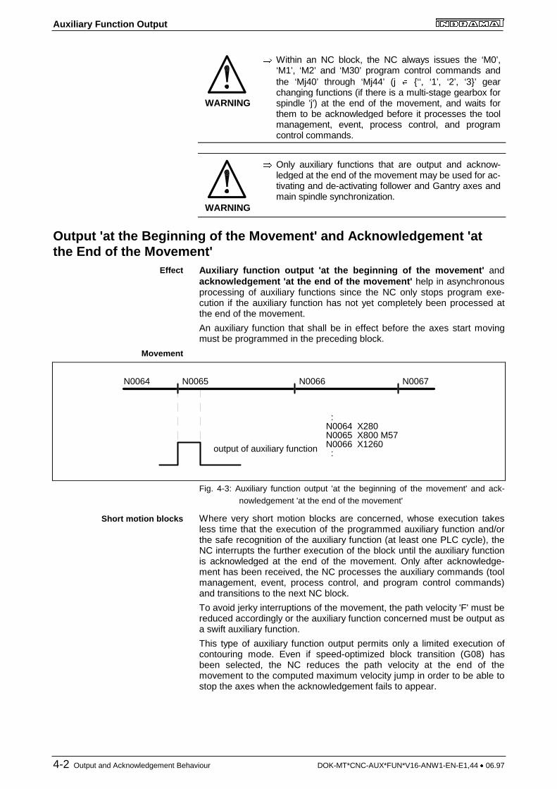
� Within an NC block, the NC always issues the ‘M0’,‘M1’, ‘M2’ and ‘M30’ program control commands andthe ‘Mj40’ through ‘Mj44’ (j � {‘‘, ‘1’, ‘2’, ‘3}’ gearchanging functions (if there is a multi-stage gearbox forspindle 'j') at the end of the movement, and waits forthem to be acknowledged before it processes the toolmanagement, event, process control, and programcontrol commands.
WARNING
� Only auxiliary functions that are output and acknow-ledged at the end of the movement may be used for ac-tivating and de-activating follower and Gantry axes andmain spindle synchronization.
Output 'at the Beginning of the Movement' and Acknowledgement 'atthe End of the Movement'
Auxiliary function output 'at the beginning of the movement' andacknowledgement 'at the end of the movement' help in asynchronousprocessing of auxiliary functions since the NC only stops program exe-cution if the auxiliary function has not yet completely been processed atthe end of the movement.
An auxiliary function that shall be in effect before the axes start movingmust be programmed in the preceding block.
output of auxiliary function
N0064 N0065 N0066 N0067
:N0064 X280N0065 X800 M57N0066 X1260 :
Fig. 4-3: Auxiliary function output 'at the beginning of the movement' and ack-nowledgement 'at the end of the movement'
Where very short motion blocks are concerned, whose execution takesless time that the execution of the programmed auxiliary function and/orthe safe recognition of the auxiliary function (at least one PLC cycle), theNC interrupts the further execution of the block until the auxiliary functionis acknowledged at the end of the movement. Only after acknowledge-ment has been received, the NC processes the auxiliary commands (toolmanagement, event, process control, and program control commands)and transitions to the next NC block.
To avoid jerky interruptions of the movement, the path velocity 'F' must bereduced accordingly or the auxiliary function concerned must be output asa swift auxiliary function.
This type of auxiliary function output permits only a limited execution ofcontouring mode. Even if speed-optimized block transition (G08) hasbeen selected, the NC reduces the path velocity at the end of themovement to the computed maximum velocity jump in order to be able tostop the axes when the acknowledgement fails to appear.
Effect
Movement
Short motion blocks

Auxiliary Function Output
DOK-MT*CNC-AUX*FUN*V16-ANW1-EN-E1,44 � 06.97 Output and Acknowledgement Behaviour 4-3
4.2 Swift Auxiliary Functions
GeneralIf, during the selection of the parameter values, the machine manufac-turer sets the acknowledgement behaviour to 'later' and if the user pro-grams an inserted 'Q' in the NC program, the NC interprets the auxiliaryfunction concerned as a swift auxiliary function. At the selected outputtime, the NC transfers 'swift auxiliary functions ' to the PLC withoutwaiting for them to be acknowledged. It does not interrupt block pro-cessing. Contouring mode without velocity-optimized block transition(G08) is possible without velocity dips. Irrespective of the output of theauxiliary function and in the same way as in operation without auxiliaryfunction output, the NC adjusts the velocity at the end of the block suchthat it transitions to the next NC block at the highest speed possible.
The user may program the swift M and Q functions without the insertedQ as normal auxiliary functions. The NC will then wait at the end of themovement for the auxiliary function concerned to be acknowledged.
The following M functions are excluded from this type of programming:
� ‘M0’, ‘M1’, ‘M2’ and ‘M30’ for program control,� spindle positioning with ‘Mj19’ for spindle ‘j’, and� gear changing commands ‘Mj40’ through ‘Mj44’
(only if there is a multi-stage gearbox for spindle 'j').
For each NC block, the user may program up to six auxiliary functions(swift, normal or mixed).
Swift M and Q Function OutputAn inserted 'Q' (for quick) enables M and Q functions that have beenselected as swift auxiliary functions by the machine manufacturer duringcommissioning, to be output as swift auxiliary functions to the PLC.
Output of swift M functions: MQxxx xxx � {0 through 999}MQ=Variable
Output of swift Q functions: QQxxxxxxxx � {0 through 9999}QQ=Variable
Instruction : The NC ensures during program execution, that only auxi-liary functions that have been set by the machine manu-facturer as to be acknowledged 'later' are output as swiftauxiliary functions.
M80: • output at the beginning
• acknowledgement later
NC program PLC program•••N0082 MQ80•••N00197MW80•••
Swift auxiliary function
Exceptions
Programming
Syntax
Example
M_FKT_Q
M_FKT
Auxiliary Function Output
4-4 Output and Acknowledgement Behaviour DOK-MT*CNC-AUX*FUN*V16-ANW1-EN-E1,44 � 06.97
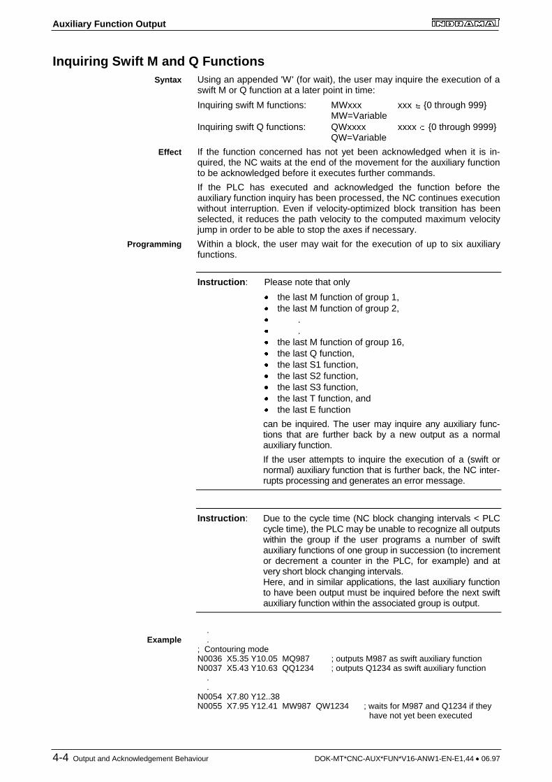
Inquiring Swift M and Q FunctionsUsing an appended 'W' (for wait), the user may inquire the execution of aswift M or Q function at a later point in time:
Inquiring swift M functions: MWxxx xxx � {0 through 999}MW=Variable
Inquiring swift Q functions: QWxxxx xxxx � {0 through 9999}QW=Variable
If the function concerned has not yet been acknowledged when it is in-quired, the NC waits at the end of the movement for the auxiliary functionto be acknowledged before it executes further commands.
If the PLC has executed and acknowledged the function before theauxiliary function inquiry has been processed, the NC continues executionwithout interruption. Even if velocity-optimized block transition has beenselected, it reduces the path velocity to the computed maximum velocityjump in order to be able to stop the axes if necessary.
Within a block, the user may wait for the execution of up to six auxiliaryfunctions.
Instruction : Please note that only
� the last M function of group 1,� the last M function of group 2,� .� .� the last M function of group 16,� the last Q function,� the last S1 function,� the last S2 function,� the last S3 function,� the last T function, and� the last E function
can be inquired. The user may inquire any auxiliary func-tions that are further back by a new output as a normalauxiliary function.
If the user attempts to inquire the execution of a (swift ornormal) auxiliary function that is further back, the NC inter-rupts processing and generates an error message.
Instruction : Due to the cycle time (NC block changing intervals < PLCcycle time), the PLC may be unable to recognize all outputswithin the group if the user programs a number of swiftauxiliary functions of one group in succession (to incrementor decrement a counter in the PLC, for example) and atvery short block changing intervals.Here, and in similar applications, the last auxiliary functionto have been output must be inquired before the next swiftauxiliary function within the associated group is output.
. .; Contouring modeN0036 X5.35 Y10.05 MQ987 ; outputs M987 as swift auxiliary functionN0037 X5.43 Y10.63 QQ1234 ; outputs Q1234 as swift auxiliary function . .N0054 X7.80 Y12..38N0055 X7.95 Y12.41 MW987 QW1234 ; waits for M987 and Q1234 if they
have not yet been executed
Syntax
Effect
Programming
Example

Auxiliary Function Output
DOK-MT*CNC-AUX*FUN*V16-ANW1-EN-E1,44 � 06.97 Output and Acknowledgement Behaviour 4-5
N0036 N0055
1
MQ987
0
1
0
QQ1234
Q function output
M function output
waiting foracknowledge-ment
MW987QW1234
...
Fig. 4-4: Typical inquiry of swift M and Q functions
Swift S, T and E Function OutputIn contrast to the M and Q functions, the S, T, and E functions are notused for activating different functions.
S functions T functions E functions
are exclusively usedfor specifying
� spindle speed,� spindle position,� surface speed,� speed limitation� grinding wheel pe-
ripheral speed
are used for specifying� tool or location
number
are used for specifying
� tool edge number
The user cannot use an appended 'Q' for influencing the output behaviourof the S, T, or E functions that has been defined by the machinemanufacturer. If the user employs the appendix 'Q' for these functions,the user interface generates an error message during syntax check.
Likewise, using an appended 'W' for waiting for the execution of an S, T,or E function is not possible either.
No Auxiliary Function OutputUsually, the machine manufacturer only selects 'no auxiliary functionoutput ' for auxiliary functions that have no functions allocated in the PLC(e.g. the spindle control commands).
M and Q functions that are not to be output can be programmed with orwithout an appended 'Q'.
Task
Programming
Task
Programming

Auxiliary Function Output
DOK-MT*CNC-AUX*FUN*V16-ANW1-EN-E1,44 � 06.97 PLC User Programming 5-1
5 PLC User Programming
5.1 Inquiring a Change in the Auxiliary Functions (with GroupSpecification)
Using the standard functions
� M_ALL,� Q_ALL,� S_ALL,� T_ALL and� E_ALL,
the PLC is able to recognize a newly output auxiliary function. Thesestandard functions can be used for skipping program sections in whichauxiliary functions are executed if there is no change, thus permittingtime-optimized program execution.
If there is a change, the PLC can either
� directly inquire (M_FKT, Q_FKT, S_FKT, T_FKT, E_FKT, see Chapter5.2, page 5-2) or read (M_NR, Q_NR, S_NR, T_NR, E_NR, see Chapter5.4, page 5-4) an auxiliary function, and, after they have been pro-cessed,
� acknowledge the auxiliary functions either individually (M_FKT_Q,Q_FKT_Q, S_FKT_Q, T_FKT_Q, E_FKT_Q, see Chapter 5.3, page 5-3), or acknowledge all pending auxiliary functions (M_ALL_Q, Q_ALL_Q,S_ALL_Q, T_ALL_Q, E_ALL_Q, see Chapter 5.5, page 5-6 ).
Using the ‘M_ALL’, ‘Q_ALL’, ‘S_ALL’, ‘T_ALL’, ‘E_ALL’ standard func-tions, it can be inquired according to the external circuitry whether the NChas output new M, Q, S, T, or E functions (and in which M function groupsand/or for which spindle they have been transferred).
M_ALL
ACTIVE PROC GROUP
BOOLBOOL
INTINT
Q_ALL The Q_NR standard function does not possess a GROUP input.
S_ALL Instead of the GROUP input, the S_NR standard func-tion has the SPINDLE input (spindle number 1 through 3
of the INT type).
T_ALL The T_NR standard function does not possess a GROUP input.
E_ALL The E_NR standard function does not possess a GROUP input.
ACTIVE 0: Inquiry of M function changes is not active
1: Inquiry of M function changes is active
PROC Process number (0 through 6)
GROUP M function group number (0 through 16)
0: Inquiry whether or not the NC has output an M function in one of the function groups 1 through 16.
1 through 16: Inquiry whether or not the NC has output an M function in the related function group 1 through 16
General
Task
Circuitry
Deviations
Signals

Auxiliary Function Output
5-2 PLC User Programming DOK-MT*CNC-AUX*FUN*V16-ANW1-EN-E1,44 � 06.97
Function 0: The standard function is not active, or the standard function is activeresult and there is no change.
1: The standard function is active, and there is achange.
��� ������ �� �� � ������� ��� � ����� � �������������������������������� ���������� �� ��� !! � �� � � �"����# $%�&' "����������������������������������������������������()*+��,-%�� (�#./+$ � �� (�#0/+1. � �� � � �� 2��������3 �� ���� � ������� 4������� ���������������������������������������������������� �
555
� ���� *� � ������� 4������� �������������������������������������������������*+��,-% �� �
5.2 Direct Inquiry of an Auxiliary Function (Specifying theNumber)
Using the following standard functions, the validity of an auxiliary functioncan be inquired in the PLC user program:
� M_FKT,� Q_FKT,� S_FKT,� T_FKT and� E_FKT.
If auxiliary functions of different functionality must be processed (as this isusually the case with M functions), this type of auxiliary function inquirytakes the least programming effort in the user program.
The ‘M_FKT’, ‘Q_FKT’, ‘S_FKT’, ‘T_FKT’, ‘E_FKT’ standard functionspermit the validity of a specific M, Q, S, T, or E function to be checkedindependently of the M function groups.
M_FKT
ACTIVE PROC NR
BOOLBOOL
INTINT
Q_FKT The NR input is of the INT type and has a value range of 0 through 9999.
S_FKT The S_FKT standard function has an additional SPINDLE input (spindle number 1 through 3 of the INT type). The NR input is of the DINT type, and has a value
range of 0 through 99999.
T_FKT The NR input is of the DINT type and has a value range of 0 through 9999999
E_FKT The NR input is of the INT type and has a value range of 0 through 9.
Example
General
Task
Circuitry
Deviations

Auxiliary Function Output
DOK-MT*CNC-AUX*FUN*V16-ANW1-EN-E1,44 � 06.97 PLC User Programming 5-3
ACTIVE 0: Auxiliary function inquiry is not active.
1: Auxiliary function inquiry is active.
PROC Process number (0 through 6)
NR M function number
Function 0: The standard function is not active or the standard function is active result and the NC has not transferred the auxiliary function concerned.
1: The standard function is active and the NC has output the auxiliary function concerned.
A specific action is to be performed in the PLC user program when theNC outputs the ‘M890’ M function.
��� ������ 6�� �� � ������� 7��� ���4�� � ��������������������������������� ���������� �� ��� !! � �� � � �"�������# $%�&' "�������������������������������������������������()*+��,-%�� (�#./+$ � �� (�#0/+1. � �� � � �� 2��������3 ���� � ������� 8 �9:( � ������������������������������������������������������ ���������� �� ���,-% � �� � � ;� $%�+* �"�������# $%�&' "�����������������������������������������������������<����#� (�#./+$ � �� 9:(�#*/ � �� � � �� 2��������3 �� ���������� �� ���,-%�; � �� �� $%�+* � � = �"����# "���������������# $%�&' "�������������������������������������� ����#� (�#./+$ � �� 9:(�#*/ � �� � � �� 2��������3 �
555
� ���� *� � ������� 4������� �������������������������������������������������*+��,-% �� �
5.3 Direct Acknowledgement of an Auxiliary Function(Specifying a Number)
All M and Q functions which the NC transfers to the PLC must be ack-nowledged in the PLC user program. Since the user is able to inquirethem with an appended 'W', this must also be done if the NC outputs theM or Q function as a swift auxiliary function.
Merely swift S, T, or E functions can do without acknowledgement; theexecution of these functions cannot be inquired from the user program.
The following standard functions are available for acknowledging theauxiliary functions which the user has initiated with the 'inquiring anauxiliary function' standard function:
� M_FKT_Q,� Q_FKT_Q,� S_FKT_Q� T_FKT_Q and� E_FKT_Q.
Signals
Example
General
Task
Auxiliary Function Output
5-4 PLC User Programming DOK-MT*CNC-AUX*FUN*V16-ANW1-EN-E1,44 � 06.97
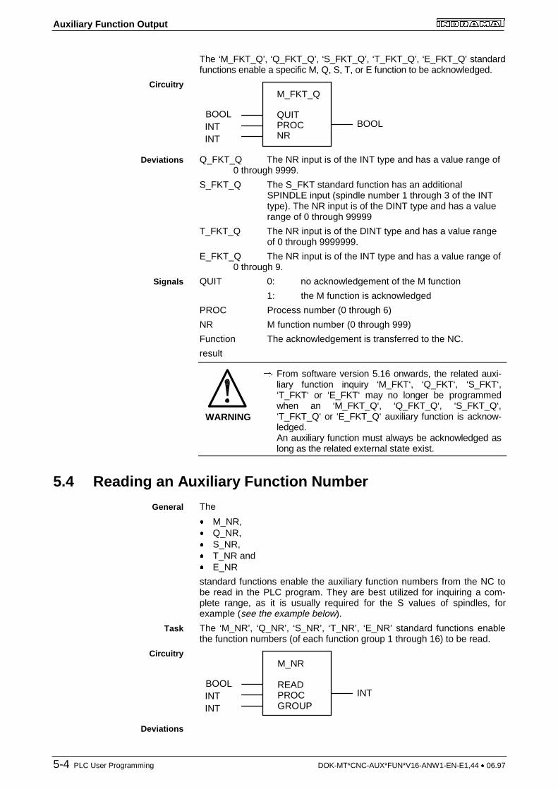
The ‘M_FKT_Q’, ‘Q_FKT_Q’, ‘S_FKT_Q’, ‘T_FKT_Q’, ‘E_FKT_Q' standardfunctions enable a specific M, Q, S, T, or E function to be acknowledged.
M_FKT_Q
QUIT PROC NR
BOOLBOOL
INTINT
Q_FKT_Q The NR input is of the INT type and has a value range of 0 through 9999.
S_FKT_Q The S_FKT standard function has an additional SPINDLE input (spindle number 1 through 3 of the INT type). The NR input is of the DINT type and has a value range of 0 through 99999
T_FKT_Q The NR input is of the DINT type and has a value range of 0 through 9999999.
E_FKT_Q The NR input is of the INT type and has a value range of 0 through 9.
QUIT 0: no acknowledgement of the M function
1: the M function is acknowledged
PROC Process number (0 through 6)
NR M function number (0 through 999)
Function The acknowledgement is transferred to the NC.
result
WARNING
� From software version 5.16 onwards, the related auxi-liary function inquiry ‘M_FKT‘, ‘Q_FKT‘, ‘S_FKT‘,‘T_FKT‘ or ‘E_FKT‘ may no longer be programmedwhen an ‘M_FKT_Q‘, ‘Q_FKT_Q‘, ‘S_FKT_Q‘,‘T_FKT_Q‘ or ‘E_FKT_Q‘ auxiliary function is acknow-ledged.An auxiliary function must always be acknowledged aslong as the related external state exist.
5.4 Reading an Auxiliary Function Number
The
� M_NR,� Q_NR,� S_NR,� T_NR and� E_NR
standard functions enable the auxiliary function numbers from the NC tobe read in the PLC program. They are best utilized for inquiring a com-plete range, as it is usually required for the S values of spindles, forexample (see the example below).
The ‘M_NR’, ‘Q_NR’, ‘S_NR’, ‘T_NR’, ‘E_NR’ standard functions enablethe function numbers (of each function group 1 through 16) to be read.
M_NR
READ PROC GROUP
BOOLINT
INTINT
Circuitry
Deviations
Signals
General
Task
Circuitry
Deviations
Auxiliary Function Output
DOK-MT*CNC-AUX*FUN*V16-ANW1-EN-E1,44 � 06.97 PLC User Programming 5-5
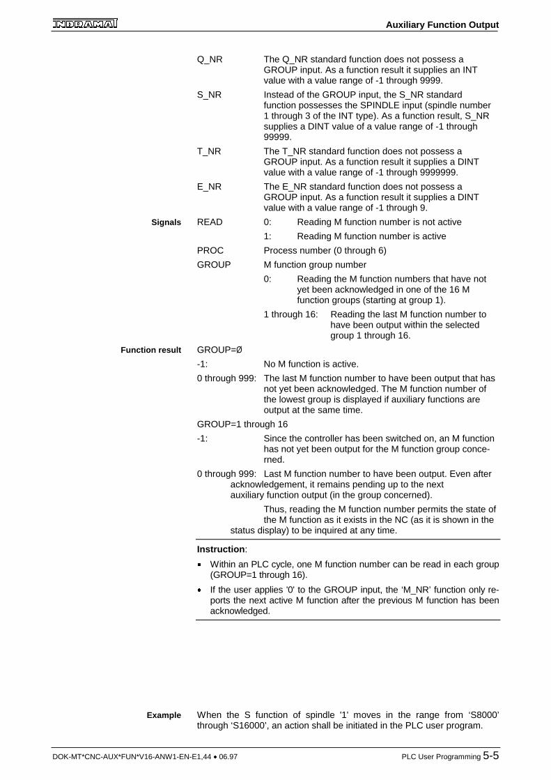
Q_NR The Q_NR standard function does not possess a GROUP input. As a function result it supplies an INT value with a value range of -1 through 9999.
S_NR Instead of the GROUP input, the S_NR standard function possesses the SPINDLE input (spindle number 1 through 3 of the INT type). As a function result, S_NR supplies a DINT value of a value range of -1 through 99999.
T_NR The T_NR standard function does not possess a GROUP input. As a function result it supplies a DINT value with a value range of -1 through 9999999.
E_NR The E_NR standard function does not possess a GROUP input. As a function result it supplies a DINT value with a value range of -1 through 9.
READ 0: Reading M function number is not active
1: Reading M function number is active
PROC Process number (0 through 6)
GROUP M function group number
0: Reading the M function numbers that have not yet been acknowledged in one of the 16 M function groups (starting at group 1).
1 through 16: Reading the last M function number to have been output within the selected group 1 through 16.
GROUP=Ø
-1: No M function is active.
0 through 999: The last M function number to have been output that has not yet been acknowledged. The M function number of the lowest group is displayed if auxiliary functions are output at the same time.
GROUP=1 through 16
-1: Since the controller has been switched on, an M function has not yet been output for the M function group conce-rned.
0 through 999: Last M function number to have been output. Even after acknowledgement, it remains pending up to the next auxiliary function output (in the group concerned).
Thus, reading the M function number permits the state of the M function as it exists in the NC (as it is shown in the
status display) to be inquired at any time.
Instruction :
� Within an PLC cycle, one M function number can be read in each group(GROUP=1 through 16).
� If the user applies '0' to the GROUP input, the ‘M_NR’ function only re-ports the next active M function after the previous M function has beenacknowledged.
When the S function of spindle '1' moves in the range from ‘S8000’through ‘S16000’, an action shall be initiated in the PLC user program.
Signals
Function result
Example

Auxiliary Function Output
5-6 PLC User Programming DOK-MT*CNC-AUX*FUN*V16-ANW1-EN-E1,44 � 06.97
��� ������ �� � � < ��� �� �4��>� ? � ����� � ��������������������������� ���������� �� �<� !! � �� � � �"�������# $%�&' "�������������������������������������������������()*+�<,-%�� (�#./+$ � �� ?�#<.�*@!' � �� � � �� 2��������3 ���� /����� � � < ��� �� �4��>� ?������������������������������������������� ���������� �� �<�*/ � �� � � �"�������#/' @ "���� <?�*/ �� (�#./+$ � �� ?�#<.�*@!' � �� � � �� 2��������3 ���� <? ��� )8 9((( � �������������������������������������������������������� ���������� �� �0' � �� � � �� <?�*/�# "���� ��<9((( �� � � �� 9(((�# � �� � � �� 2��������3 ���� <? ��� A8 ?B((( � ������������������������������������������������������� ���������� �� �!' � �� � � �� <?�*/�# "���� ��<?B((( �� � � �� ?B(((�# � �� � � �� 2��������3 ���� ����C � �D � �E � ���F� ��� < � � � � ����� ���� ������������� ��<9((( ��<?B((( ���D ;� $%�+* �"��# "�������# "���G���# "����G���������������������������������������� ����#� � ���E � �� 2���# "����3 �� �
��� �H���>����� < ������� �� �4��>� ? ������������������������������������ ���������� �� �<� !!�; � �� �� $%�+* � � = �"��# "���������#;1�% "���������������������������������������������� ����#� (�#./+$ � �� ?�#<.�*@!' � �� � � �� 2��������3 ���� *� < ������� 4������� �������������������������������������������������*+�<,-% �� �

Auxiliary Function Output
DOK-MT*CNC-AUX*FUN*V16-ANW1-EN-E1,44 � 06.97 PLC User Programming 5-7
5.5 Acknowledging an Auxiliary Function (Specifying theGroup)
The
� M_ALL_Q,� Q_ALL_Q� S_ALL_Q,� T_ALL_Q and� E_ALL_Q
standard functions enable an executed auxiliary function to be acknow-ledged.
The ‘M_ALL_Q’, ‘Q_ALL_Q’, ‘S_ALL_Q’, ‘T_ALL_Q’, ‘E_ALL_Q’ standardfunctions permit all pending functions to be acknowledged according tothe circuitry.
M_ALL_Q
QUIT PROC GROUP
BOOLBOOL
INTINT
Q_ALL_Q The Q_ALL_Q standard function does not possess a GROUP input.
S_ALL_Q Instead of the GROUP input, the S_NR standard func-tion possesses the SPINDLE input (spindle number 1 through 3 of the INT type).
T_ALL_Q The T_NR standard function does not possess a GROUP input.
E_ALL_Q The E_NR standard function does not possess a GROUP input.
QUIT 0: No acknowledgement of the M function
1: The auxiliary function is acknowledged
PROC Process number (0 through 6)
GROUP M function group number
0: Acknowledgement of all pending M functions in all M function groups.
1 through 16: Acknowledgement of the pending M function in the selected M function group 1 through 16.
Function The acknowledgement is transferred to the NC.
result
General
Task
Circuitry
Deviations
Signals

Auxiliary Function Output
5-8 PLC User Programming DOK-MT*CNC-AUX*FUN*V16-ANW1-EN-E1,44 � 06.97
5.6 Sequence of the M00, M01, M02, and M30 Function Output
M Functions M00 and M01Irrespective of the programmed sequence in the NC block, the NCtransfers the M functions M00 (unconditional stop) and M01 (conditionalstop) to the PLC at the end of the movement. The NC stops NC blockexecution (PxxSRUN = 0) as soon as the auxiliary function concerned hasbeen acknowledged and the NC has processed the remainder of theblock.
The NC continues program execution (PxxSRUN = 1) upon the nextforward or backward start (PxxCADV, PxxCREV).
After the NC block has been terminated, the programmed M00 or M01function appears in the status display until the program is restarted.
M00 auxiliary function output
Program interruptionN0066
forward or backward program start (PxxCADV, PxxCREV)
Program stopped (PxxSSTOP)
Block active (PxxSRUN)
Program active(PxxSACTIV)
N0067
1
0
Program start
M00 acknowledgement
M00 output
:
:N0067 X1260N0066 X800 M00
1
0
1
0
1
0
1
0
NC block terminated
Fig. 5-5: Interface signals for the transfer of the M00 and M01 auxiliary functions
Instruction : In the case of the M00 and M01 functions and with theHLT command, the NC does not set the 'Program halted'(PxxSSTOP) status signal.
Sequence
Interface signals

Auxiliary Function Output
DOK-MT*CNC-AUX*FUN*V16-ANW1-EN-E1,44 � 06.97 PLC User Programming 5-9
M Functions M02 and M30Irrespective of the programmed sequence in the NC block, the NC trans-fers the M functions M02 and M30 to the PLC at the end of the move-ment. The NC terminates program execution and resets the program(PxxSACTIV = 0 and PxxSRUN = 0) as soon as the auxiliary functionconcerned has been acknowledged and the NC has processed the re-mainder of the block.
The NC restarts program execution upon the next forward or backwardstart (PxxCADV, PxxCREV).
After the NC program has been terminated, the programmed M30 or M02function appears in the status display until the program is restarted.
M30 auxiliary function output
Program endN0487
Forward or backward program start (PxxCADV, PxxCREV)
Program stopped(PxxSSTOP)
Block active(PxxSRUN)
Program active (PxxSACTIV)
N0000
1
0
Program start
M30 acknowledgement
M30 output
:
:N0487 X800 M30N0486 X67
1
0
1
0
1
0
1
0
NC block and NC program terminated
Fig. 5-6: Interface signals for the transfer of the M02 and M30 auxiliary functions
Sequence
Interface signals
Auxiliary Function Output
DOK-MT*CNC-AUX*FUN*V16-ANW1-EN-E1,44 � 06.97 Index 6-1
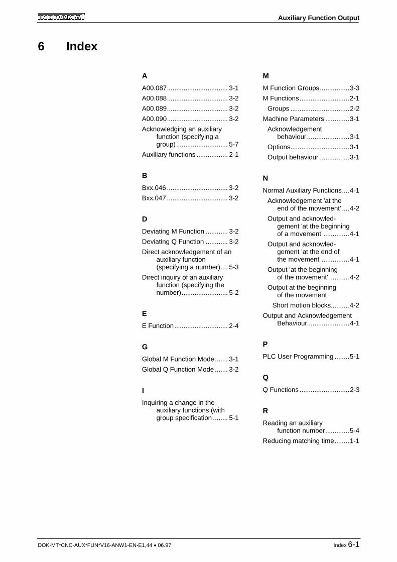
6 Index
A
A00.087................................. 3-1
A00.088................................. 3-2
A00.089................................. 3-2
A00.090................................. 3-2
Acknowledging an auxiliaryfunction (specifying agroup)............................ 5-7
Auxiliary functions ................. 2-1
B
Bxx.046 ................................. 3-2
Bxx.047 ................................. 3-2
D
Deviating M Function ............ 3-2
Deviating Q Function ............ 3-2
Direct acknowledgement of anauxiliary function(specifying a number).... 5-3
Direct inquiry of an auxiliaryfunction (specifying thenumber)......................... 5-2
E
E Function............................. 2-4
G
Global M Function Mode....... 3-1
Global Q Function Mode ....... 3-2
I
Inquiring a change in theauxiliary functions (withgroup specification ........ 5-1
M
M Function Groups................3-3
M Functions...........................2-1
Groups ................................2-2
Machine Parameters .............3-1
Acknowledgementbehaviour .......................3-1
Options................................3-1
Output behaviour ................3-1
N
Normal Auxiliary Functions....4-1
Acknowledgement 'at theend of the movement' ....4-2
Output and acknowled-gement 'at the beginningof a movement’ ..............4-1
Output and acknowled-gement 'at the end ofthe movement' ...............4-1
Output 'at the beginningof the movement' ...........4-2
Output at the beginningof the movement
Short motion blocks..........4-2
Output and AcknowledgementBehaviour.......................4-1
P
PLC User Programming ........5-1
Q
Q Functions ...........................2-3
R
Reading an auxiliaryfunction number.............5-4
Reducing matching time........1-1
Auxiliary Function Output
6-2 Index DOK-MT*CNC-AUX*FUN*V16-ANW1-EN-E1,44 � 06.97
S
S Function Mode................... 3-2
S Functions ........................... 2-3
Sequence of the M FunctionsM00 and M01 ................ 5-8
Sequence of the M Func-tions M02 and M30........ 5-9
Swift auxiliary function
No Auxiliary FunctionOutput ........................... 4-5
Swift auxiliary functions......... 4-3
Contouring mode................ 4-3
Inquiring SwiftM Functions ...................4-4
Inquiring SwiftQ Functions ...................4-4
Swift M and Q Function Output.......................................4-3
Swift S, T and E FunctionOutput............................4-5
T
T Function .............................2-4
T/E Function Mode ................3-2
Time-optimized processingof auxiliary functions ......1-1

Auxiliary Function Output
DOK-MT*CNC-AUX*FUN*V16-ANW1-EN-E1,44 � 06.97 Table of Figure 7-1
7 Table of FigureFig. 4-1: Input of auxiliary
function 'at the beginningof the movement' andacknowledgement 'atthe beginning of themovement' ..................... 4-1
Fig. 4-2: Input of auxiliaryfunction 'at the beginning ofthe movement' and acknow-ledgement 'at the beginningof the movement'............ 4-1
Fig. 4-3: Auxiliary functionoutput 'at the beginningof the movement' andacknowledgement 'atthe end of themovement'......................4-2
Fig. 4-4: Typical inquiry of swiftM and Q functions ..........4-5
Fig. 5-5: Interface signals forthe transfer of the M00and M01 auxiliaryfunctions.........................5-8
Fig. 5-6: Interface signals forthe transfer of the M02and M30 auxiliaryfunctions.........................5-9

Auxiliary Function Output
DOK-MT*CNC-AUX*FUN*V16-ANW1-EN-E1,44 � 06.97 Verzeichnis der Kundenbetreuungsstellen
Customer ServiceGermany
Vertriebsgebiet Mitte
INDRAMAT GmbHD-97816 Lohr am MainBgm.-Dr.-Nebel-Str. 2
Telefon: 09352/40-0Telefax: 09352/40-4885
Vertriebsgebiet Ost
INDRAMAT GmbHD-09120 ChemnitzBeckerstraße 31
Telefon: 0371/3555-0Telefax: 0371/3555-230
Vertriebsgebiet West
INDRAMAT GmbHD-40849 RatingenHansastraße 25
Telefon: 02102/4318-0Telefax: 02102/41315
Vertriebsgebiet Nord
INDRAMAT GmbHD-22085 HamburgFährhausstraße 11
Telefon: 040/227126-16Telefax: 040/227126-15
Vertriebsgebiet Süd
INDRAMAT GmbHD-80339 MünchenRidlerstraße 75
Telefon: 089/540138-30Telefax: 089/540138-10
Vertriebsgebiet Südwest
INDRAMAT GmbHD-71229 LeonbergBöblinger Straße 25
Telefon: 07152/972-6Telefax: 07152/972-727
INDRAMAT Service-Hotline
INDRAMAT GmbHTelefon: D-0172/660 040 6
-oder-
Telefon: D-0171/333 882 6
Customer Service in Germany
EuropeAustria
G.L.Rexroth Ges.m.b.H.Geschäftsbereich INDRAMATA-1140 WienHägelingasse 3
Telefon: 1/9852540-400Telefax:1/9852540-93
Austria
G.L.Rexroth Ges.m.b.H.Geschäftsbereich INDRAMATA-4061 PaschingRandlstraße 14
Telefon: 07229/4401-36Telefax: 07229/4401-80
Belgium
Mannesmann Rexroth N.V.-S.A.Geschäftsbereich INDRAMATB-1740 TernatIndustrielaan 8
Telefon: 02/5823180Telefax: 02/5824310
Denmark
BEC Elektronik ASDK-8900 RandersZinkvej 6
Telefon: 086/447866Telefax: 086/447160
England
Mannesmann Rexroth Ltd.INDRAMAT DivisionCirencester, Glos GL7 1YG4 Esland Place, Love Lane
Telefon: 01285/658671Telefax: 01285/654991
Finnland
Rexroth Mecman OYSF-01720 VantaaRiihimiehentie 3
Telefon: 0/848511Telefax: 0/846387
France
Rexroth - Sigma S.A.Division INDRAMATF-92632 Gennevilliers CedexParc des Barbanniers 4,Place du Village
Telefon: 1/41475430Telefax: 1/47946941
France
Rexroth - Sigma S.A.Division INDRAMATF-69634 Venissieux - Cx91, Bd 1 Joliot Curie
Telefon: 78785256Telefax: 78785231
France
Rexroth - Sigma S.A.Division INDRAMATF-31100 Toulouse270, Avenue de lardenne
Telefon: 61499519Telefax: 61310041
Italy
Rexroth S.p.A.Divisione INDRAMATI-20063 Cernusco S/N.MIVia G. Di Vittoria, 1
Telefon: 02/92365-270Telefax: 02/92108069
Italy
Rexroth S.p.A. DivisioneINDRAMATVia Borgomanero, 11I-10145 Torino
Telefon: 011/7712230Telefax: 011/7710190
Netherlands
Hydraudyne Hydrauliek B.V.Kruisbroeksestraat 1aP.O. Box 32NL-5280 AA Boxtel
Telefon: 04116/51951Telefax: 04116/51483
Spain
Rexroth S.A.Centro Industrial SantiagoObradors s/nE-08130 Santa Perpetua deMogoda (Barcelona)
Telefon: 03/718 68 51Telex: 591 81Telefax: 03/718 98 62
Spain
Goimendi S.A.División IndramatJolastokieta (Herrera)Apartado 11 37San Sebastion, 20017
Telefon: 043/40 01 63Telex: 361 72Telefax: 043/39 93 95
Sweden
AB Rexroth MecmanINDRAMAT DivisionVaruvägen 7S-125 81 Stockholm
Telefon: 08/727 92 00Telefax: 08/64 73 277
Switzerland
Rexroth SADépartement INDRAMATChemin de l`Ecole 6CH-1036 Sullens
Telefon: 021/731 43 77Telefax: 021/731 46 78
Switzerland
Rexroth AGGeeschäftsbereich INDRAMATGewerbestraße 3CH-8500 Frauenfeld
Telefon: 052/720 21 00Telefax: 052/720 21 11
Russia
Tschudnenko E.B.Arsenia 22153000 IvanovoRußland
Telefon: 093/22 39 633
Customer Service in Europe
Auxiliary Function Output
Verzeichnis der Kundenbetreuungsstellen DOK-MT*CNC-AUX*FUN*V16-ANW1-EN-E1,44 � 06.97
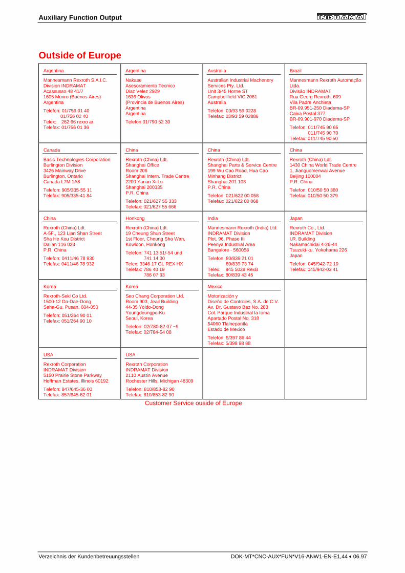
Outside of EuropeArgentina
Mannesmann Rexroth S.A.I.C.Division INDRAMATAcassusso 48 41/71605 Munro (Buenos Aires)Argentina
Telefon: 01/756 01 40 01/756 02 40Telex: 262 66 rexro arTelefax: 01/756 01 36
Argentina
NakaseAsesoramiento TecnicoDiaz Velez 29291636 Olivos(Provincia de Buenos Aires)ArgentinaArgentina
Telefon 01/790 52 30
Australia
Australian Industrial MacheneryServices Pty. Ltd.Unit 3/45 Horne STCampbellfield VIC 2061Australia
Telefon: 03/93 59 0228Telefax: 03/93 59 02886
Brazil
Mannesmann Rexroth AutomaçãoLtda.Divisão INDRAMATRua Georg Rexroth, 609Vila Padre AnchietaBR-09.951-250 Diadema-SPCaixa Postal 377BR-09.901-970 Diadema-SP
Telefon: 011/745 90 65 011/745 90 70Telefax: 011/745 90 50
Canada
Basic Technologies CorporationBurlington Division3426 Mainway DriveBurlington, OntarioCanada L7M 1A8
Telefon: 905/335-55 11Telefax: 905/335-41 84
China
Rexroth (China) Ldt.Shanghai OfficeRoom 206Shanghai Intern. Trade Centre2200 Yanan Xi LuShanghai 200335P.R. China
Telefon: 021/627 55 333Telefax: 021/627 55 666
China
Rexroth (China) Ldt.Shanghai Parts & Service Centre199 Wu Cao Road, Hua CaoMinhang DistrictShanghai 201 103P.R. China
Telefon: 021/622 00 058Telefax: 021/622 00 068
China
Rexroth (China) Ldt.1430 China World Trade Centre1, Jianguomenwai AvenueBeijing 100004P.R. China
Telefon: 010/50 50 380Telefax: 010/50 50 379
China
Rexroth (China) Ldt.A-5F., 123 Lian Shan StreetSha He Kou DistrictDalian 116 023P.R. China
Telefon: 0411/46 78 930Telefax: 0411/46 78 932
Honkong
Rexroth (China) Ldt.19 Cheung Shun Street1st Floor, Cheung Sha Wan,Kowloon, Honkong
Telefon: 741 13 51/-54 und 741 14 30Telex: 3346 17 GL REX HXTelefax: 786 40 19 786 07 33
India
Mannesmann Rexroth (India) Ltd.INDRAMAT DivisionPlot. 96, Phase IIIPeenya Industrial AreaBangalore - 560058
Telefon: 80/839 21 01 80/839 73 74Telex: 845 5028 RexBTelefax: 80/839 43 45
Japan
Rexroth Co., Ltd.INDRAMAT DivisionI.R. BuildingNakamachidai 4-26-44Tsuzuki-ku, Yokohama 226Japan
Telefon: 045/942-72 10Telefax: 045/942-03 41
Korea
Rexroth-Seki Co Ltd.1500-12 Da-Dae-DongSaha-Gu, Pusan, 604-050
Telefon: 051/264 90 01Telefax: 051/264 90 10
Korea
Seo Chang Corporation Ltd.Room 903, Jeail Building44-35 Yoido-DongYoungdeungpo-KuSeoul, Korea
Telefon: 02/780-82 07 ~9Telefax: 02/784-54 08
Mexico
Motorización yDiseño de Controles, S.A. de C.V.Av. Dr. Gustavo Baz No. 288Col. Parque Industrial la IomaApartado Postal No. 31854060 TlalnepantlaEstado de Mexico
Telefon: 5/397 86 44Telefax: 5/398 98 88
USA
Rexroth CorporationINDRAMAT Division5150 Prairie Stone ParkwayHoffman Estates, Illinois 60192
Telefon: 847/645-36 00Telefax: 857/645-62 01
USA
Rexroth CorporationINDRAMAT Division2110 Austin AvenueRochester Hills, Michigan 48309
Telefon: 810/853-82 90Telefax: 810/853-82 90
Customer Service ouside of Europe

Indramat


