7
www.maselec.com Email: [email protected] Phone: +44 (0)1628-770 104 MTC-1X Stereo Mastering Transfer Console

www.maselec.com Email: [email protected] Phone: +44 (0)1628-770 104
MTC-1X Stereo Mastering Transfer Console

www.maselec.com Email: [email protected] Phone: +44 (0)1628-770 104
MTC-1X Stereo Mastering Transfer Console
The MTC-1X measures 3 U height with a depth ‘behind panel’ of 260mm and 10kg weight. The front control surface has 43 push-button controls with LED lights and 12 high quality rotary switches.
Gold XLRs are used for all audio connections, assisting the use of highest quality cables. Connecting and rearranging external equipment is very easy.
The MTC-1X is structured into four different sections:
1. The Input section:
� Input source selection � Phase invert for left and right � Separate Left and Right gain controls (1/2dB steps) � 5dB additional gain selectable for low level sources � Low-cut and High-cut filters � Independent Cut controls for left and right
3. The Output section:
� Separate Left and Right gain controls (1/2dB steps) � Elliptical filter with 20 frequencies * � Stereo Width control; from mono to extra wide * � Output Cut control
* The stereo image circuits are identical to the famous controls of the MTC-2.
2. The Insert section has six insert points and offers
additional powerful functions:
� M-S with gain control for the ‘difference’ signal � Inserts 1 & 2 equipment swap (FLIP) � Insert 4 or Inserts 2-4 cross-fade or additive mix with
the use of a rotary switch. This function could be used for ‘parallel’ compression or adding reverb
� Inserts 4 & 5 equipment swap (FLIP) � Insert 6 can be moved to Post Output. This is the
preferred position for a brick-wall limiter.
4. The Monitor section:
� 4 external Monitor Sources � Monitor of the Input and Output sections � 2 speaker feeds � 0 to10dB, 1/2dB steps, offset trim for inputs S1 and S2 � Monitor of the Stereo-, Left-, Right-, Mono-
or Difference- signal � Individual Cut controls for Left and Right speakers � Progressive Dim function � Meter output, with –6dB, -8dB and –10dB offsets
www.maselec.com Email: [email protected] Phone: +44 (0)1628-770 104
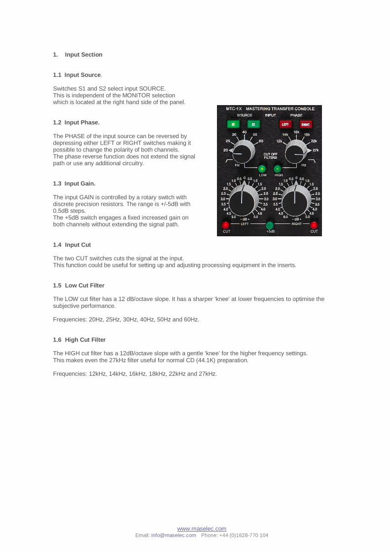
1. Input Section 1.1 Input Source. Switches S1 and S2 select input SOURCE. This is independent of the MONITOR selection which is located at the right hand side of the panel. 1.2 Input Phase. The PHASE of the input source can be reversed by depressing either LEFT or RIGHT switches making it possible to change the polarity of both channels. The phase reverse function does not extend the signal path or use any additional circuitry. 1.3 Input Gain. The input GAIN is controlled by a rotary switch with discrete precision resistors. The range is +/-5dB with 0.5dB steps. The +5dB switch engages a fixed increased gain on both channels without extending the signal path. 1.4 Input Cut The two CUT switches cuts the signal at the input. This function could be useful for setting up and adjusting processing equipment in the inserts. 1.5 Low Cut Filter The LOW cut filter has a 12 dB/octave slope. It has a sharper ‘knee’ at lower frequencies to optimise the subjective performance. Frequencies: 20Hz, 25Hz, 30Hz, 40Hz, 50Hz and 60Hz. 1.6 High Cut Filter The HIGH cut filter has a 12dB/octave slope with a gentle ‘knee’ for the higher frequency settings. This makes even the 27kHz filter useful for normal CD (44.1K) preparation. Frequencies: 12kHz, 14kHz, 16kHz, 18kHz, 22kHz and 27kHz.

www.maselec.com Email: [email protected] Phone: +44 (0)1628-770 104
2. INSERTS 2.1 Insert Select Inserts in/out is selected with six large push buttons. The insert section is totally bypassed unless at least one insert is in circuit. This ensures that the signal path is as pure as possible. 2.2 Gear Flip. The GEAR FLIP function switches the position of the equipment connected to the XLR connectors on the back of the MTC-1X. It does not alter the position of the inserts. When FLIP 1 and 2 is engaged Insert 1 is still the first insert in the chain. This function is also active when M-S is selected. Flip 4 and 5 works in a similar way.
2.3 Post Output The POST O.P. function moves insert 6 to post the output section. This positions the insert between the output amplifiers and the output XLRs. The monitor of the output is picking up the signal from the XLR connectors and correctly monitors the output signal, post insert 6, when this function is used.
2.4 Insert 1 M-S INS 1 M-S converts the signal in Insert 1 to MS (sum and difference). Left channel = Sum and Right channel = Difference. When this function is engaged the difference signal gain can be adjusted +/-1dB with a rotary switch. The DIFF GAIN control is located after the insert. The Flip 1 and 2 can be used together with the M-S function.
2.5 Insert 4 Mix The INS 4 MIX function makes it possible to mix processed signals with the main signal. This is done with the 23 position rotary switch. The Mix function can be configured in two ways:
2.5.1 Cross-Fade.
The control cross-fades between processed (after insert 4) and non-processed (before insert 4) signals. The output level remains constant in all positions (if the two levels are the same). This is probably the most convenient way of mixing the signals.
2.5.2 Add
With this control engaged the signal from insert 4 is added to the main signal, much like a reverb return on a mixing console. This could be useful when adding an effect or a separate signal to the main programme.
2.6 2-4 When the 2-4 control is engaged, the signal processed in insert 2, insert 3 and insert 4 is mixed with the non-processed signal before insert 2. Only the inserts that are in circuit will of course be mixed. If none of these three inserts are in circuit the mix control is totally bypassed. Together with the FLIP function the INS 4 MIX is a very flexible and powerful tool and could be used for parallel processing, using the equipment in up to three different inserts. The headroom of the MTC-1X is not affected by this function.
www.maselec.com Email: [email protected] Phone: +44 (0)1628-770 104
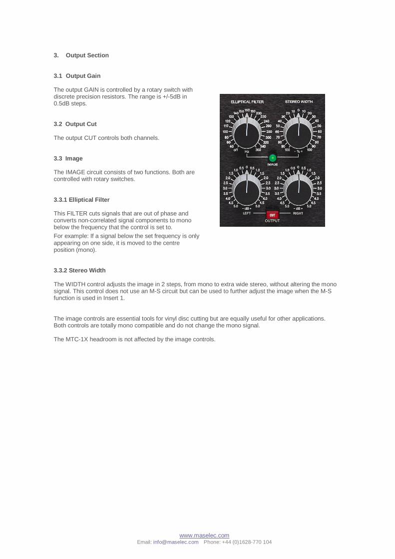
3. Output Section 3.1 Output Gain The output GAIN is controlled by a rotary switch with discrete precision resistors. The range is +/-5dB in 0.5dB steps. 3.2 Output Cut The output CUT controls both channels. 3.3 Image The IMAGE circuit consists of two functions. Both are controlled with rotary switches. 3.3.1 Elliptical Filter This FILTER cuts signals that are out of phase and converts non-correlated signal components to mono below the frequency that the control is set to.
For example: If a signal below the set frequency is only appearing on one side, it is moved to the centre position (mono). 3.3.2 Stereo Width The WIDTH control adjusts the image in 2 steps, from mono to extra wide stereo, without altering the mono signal. This control does not use an M-S circuit but can be used to further adjust the image when the M-S function is used in Insert 1. The image controls are essential tools for vinyl disc cutting but are equally useful for other applications. Both controls are totally mono compatible and do not change the mono signal. The MTC-1X headroom is not affected by the image controls.
www.maselec.com Email: [email protected] Phone: +44 (0)1628-770 104
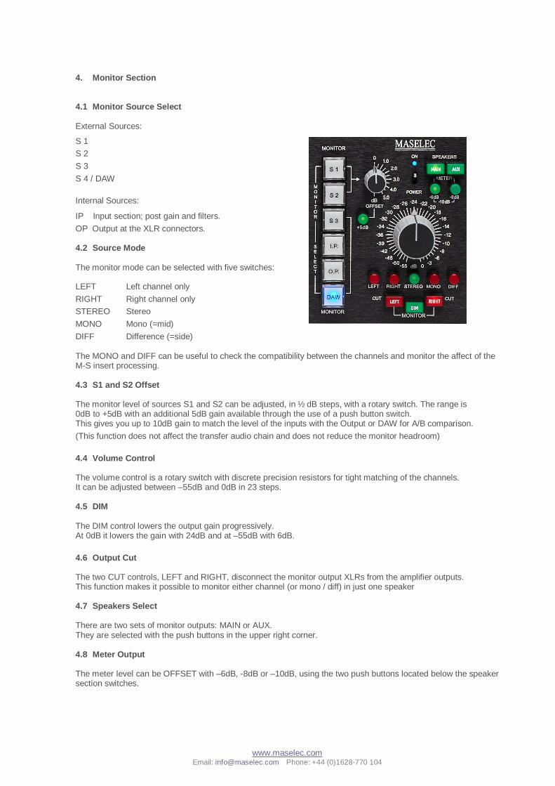
4. Monitor Section 4.1 Monitor Source Select External Sources:
S 1
S 2
S 3
S 4 / DAW
Internal Sources:
IP Input section; post gain and filters.
OP Output at the XLR connectors. 4.2 Source Mode The monitor mode can be selected with five switches:
LEFT Left channel only y
RIGHT Right channel only
STEREO Stereo
MONO Mono (=mid)
DIFF Difference (=side) The MONO and DIFF can be useful to check the compatibility between the channels and monitor the affect of the M-S insert processing. 4.3 S1 and S2 Offset The monitor level of sources S1 and S2 can be adjusted, in ½ dB steps, with a rotary switch. The range is 0dB to +5dB with an additional 5dB gain available through the use of a push button switch. This gives you up to 10dB gain to match the level of the inputs with the Output or DAW for A/B comparison.
(This function does not affect the transfer audio chain and does not reduce the monitor headroom)
4.4 Volume Control The volume control is a rotary switch with discrete precision resistors for tight matching of the channels. It can be adjusted between –55dB and 0dB in 23 steps. 4.5 DIM The DIM control lowers the output gain progressively. At 0dB it lowers the gain with 24dB and at –55dB with 6dB.
4.6 Output Cut The two CUT controls, LEFT and RIGHT, disconnect the monitor output XLRs from the amplifier outputs. This function makes it possible to monitor either channel (or mono / diff) in just one speaker
4.7 Speakers Select There are two sets of monitor outputs: MAIN or AUX. They are selected with the push buttons in the upper right corner.
4.8 Meter Output The meter level can be OFFSET with –6dB, -8dB or –10dB, using the two push buttons located below the speaker section switches.
www.maselec.com Email: [email protected] Phone: +44 (0)1628-770 104
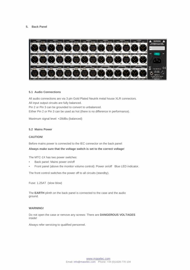
5. Back Panel
5.1 Audio Connections All audio connections are via 3 pin Gold Plated Neutrik metal house XLR connectors.
All input output circuits are fully balanced.
Pin 2 or Pin 3 can be grounded to convert to unbalanced.
Either Pin 2 or Pin 3 can be used as hot (there is no difference in performance).
Maximum signal level: +28dBu (balanced)
5.2 Mains Power CAUTION! Before mains power is connected to the IEC connector on the back panel:
Always make sure that the voltage switch is set to the correct voltage!
The MTC-1X has two power switches:
• Back panel: Mains power on/off
• Front panel (above the monitor volume control): Power on/off Blue LED indicator. The front control switches the power off to all circuits (standby). Fuse: 1.25AT (slow blow) The EARTH plinth on the back panel is connected to the case and the audio ground.
WARNING! Do not open the case or remove any screws: There are DANGEROUS VOLTAGES inside! Always refer servicing to qualified personnel.


