34
© 2009 Microchip Technology Inc. DS41407A mTouch ™ Inductive Touch User’s Guide
© 2009 Microchip Technology Inc. DS41407A
mTouch™ Inductive Touch User’s Guide
Note the following details of the code protection feature on Microchip devices:• Microchip products meet the specification contained in their particular Microchip Data Sheet.
• Microchip believes that its family of products is one of the most secure families of its kind on the market today, when used in the intended manner and under normal conditions.
• There are dishonest and possibly illegal methods used to breach the code protection feature. All of these methods, to our knowledge, require using the Microchip products in a manner outside the operating specifications contained in Microchip’s Data Sheets. Most likely, the person doing so is engaged in theft of intellectual property.
• Microchip is willing to work with the customer who is concerned about the integrity of their code.
• Neither Microchip nor any other semiconductor manufacturer can guarantee the security of their code. Code protection does not mean that we are guaranteeing the product as “unbreakable.”
Code protection is constantly evolving. We at Microchip are committed to continuously improving the code protection features of ourproducts. Attempts to break Microchip’s code protection feature may be a violation of the Digital Millennium Copyright Act. If such actsallow unauthorized access to your software or other copyrighted work, you may have a right to sue for relief under that Act.
Information contained in this publication regarding deviceapplications and the like is provided only for your convenienceand may be superseded by updates. It is your responsibility toensure that your application meets with your specifications.MICROCHIP MAKES NO REPRESENTATIONS ORWARRANTIES OF ANY KIND WHETHER EXPRESS ORIMPLIED, WRITTEN OR ORAL, STATUTORY OROTHERWISE, RELATED TO THE INFORMATION,INCLUDING BUT NOT LIMITED TO ITS CONDITION,QUALITY, PERFORMANCE, MERCHANTABILITY ORFITNESS FOR PURPOSE. Microchip disclaims all liabilityarising from this information and its use. Use of Microchipdevices in life support and/or safety applications is entirely atthe buyer’s risk, and the buyer agrees to defend, indemnify andhold harmless Microchip from any and all damages, claims,suits, or expenses resulting from such use. No licenses areconveyed, implicitly or otherwise, under any Microchipintellectual property rights.
DS41407A-page 2
Trademarks
The Microchip name and logo, the Microchip logo, dsPIC, KEELOQ, KEELOQ logo, MPLAB, PIC, PICmicro, PICSTART, rfPIC and UNI/O are registered trademarks of Microchip Technology Incorporated in the U.S.A. and other countries.
FilterLab, Hampshire, HI-TECH C, Linear Active Thermistor, MXDEV, MXLAB, SEEVAL and The Embedded Control Solutions Company are registered trademarks of Microchip Technology Incorporated in the U.S.A.
Analog-for-the-Digital Age, Application Maestro, CodeGuard, dsPICDEM, dsPICDEM.net, dsPICworks, dsSPEAK, ECAN, ECONOMONITOR, FanSense, HI-TIDE, In-Circuit Serial Programming, ICSP, Mindi, MiWi, MPASM, MPLAB Certified logo, MPLIB, MPLINK, mTouch, Octopus, Omniscient Code Generation, PICC, PICC-18, PICDEM, PICDEM.net, PICkit, PICtail, PIC32 logo, REAL ICE, rfLAB, Select Mode, Total Endurance, TSHARC, UniWinDriver, WiperLock and ZENA are trademarks of Microchip Technology Incorporated in the U.S.A. and other countries.
SQTP is a service mark of Microchip Technology Incorporated in the U.S.A.
All other trademarks mentioned herein are property of their respective companies.
© 2009, Microchip Technology Incorporated, Printed in the U.S.A., All Rights Reserved.
Printed on recycled paper.
© 2009 Microchip Technology Inc.
Microchip received ISO/TS-16949:2002 certification for its worldwide headquarters, design and wafer fabrication facilities in Chandler and Tempe, Arizona; Gresham, Oregon and design centers in California and India. The Company’s quality system processes and procedures are for its PIC® MCUs and dsPIC® DSCs, KEELOQ® code hopping devices, Serial EEPROMs, microperipherals, nonvolatile memory and analog products. In addition, Microchip’s quality system for the design and manufacture of development systems is ISO 9001:2000 certified.
INDUCTIVE TOUCH DEMO BOARDUSER’S GUIDE
Table of Contents
Chapter 1. Introduction1.1 Introduction ................................................................................................... 111.2 Development Kit Contents ............................................................................ 111.3 Inductive Touch Demonstration Board ......................................................... 111.4 Sample Code ................................................................................................ 12
Chapter 2. Getting Started2.1 Inductive Touch Demo Board as a Stand-Alone Board –
Preprogrammed Device .......................................................................... 132.2 Inductive Touch Demo Board Used with an In-Circuit Debugger ................. 132.3 Inductive Touch Demo Board Connection to the mTouch™ GUI ................. 14
Chapter 3. Theory of Operation3.1 Sensor Coil Impedance Measurement System ............................................ 193.2 Polling Software ........................................................................................... 20
Appendix A. System DetailA.1 Sensor Design ............................................................................................. 23
A.1.1 Fascia ....................................................................................................... 23A.1.2 Targets ...................................................................................................... 24A.1.3 Spacer ...................................................................................................... 24A.1.4 Sensor Coils .............................................................................................. 24
A.2 Hardware Design ......................................................................................... 25A.3 Power Supply ............................................................................................... 27A.4 Software Design ........................................................................................... 28A.5 Board Layout and Schematic ....................................................................... 30
© 2009 Microchip Technology Inc. DS41407A-page 3

Inductive Touch Demo Board User’s Guide
NOTES:
DS41407A-page 4 © 2009 Microchip Technology Inc.

INDUCTIVE TOUCH DEMO BOARDUSER’S GUIDE
Preface
INTRODUCTIONThis chapter contains general information that will be useful to know before using the Inductive Touch Demo Board. Items discussed in this chapter include:• Document Layout• Conventions Used in this Guide• Warranty Registration• Recommended Reading• The Microchip Web Site• Development Systems Customer Change Notification Service• Customer Support• Document Revision History
DOCUMENT LAYOUTThis document describes how to use the Inductive Touch Demo Board as a development tool to emulate and debug firmware on a target board. The manual layout is as follows: • Chapter 1. “Introduction” – Introduces the Inductive Touch Demo Board and
provides a brief description of the system.• Chapter 2. “Getting Started” – Goes through a basic step-by-step process for
getting your Inductive Touch Demo Board up and running as a stand-alone board or with the mTouch™ GUI.
• Chapter 3. “Theory of Operation” – Provides an overview of how the Inductive Touch system operates.
• Appendix A. “System Detail” – Describes in detail the operation of the Demo Board hardware and software.
NOTICE TO CUSTOMERS
All documentation becomes dated, and this manual is no exception. Microchip tools and documentation are constantly evolving to meet customer needs, so some actual dialogs and/or tool descriptions may differ from those in this document. Please refer to our web site (www.microchip.com) to obtain the latest documentation available.
Documents are identified with a “DS” number. This number is located on the bottom of each page, in front of the page number. The numbering convention for the DS number is “DSXXXXXA”, where “XXXXX” is the document number and “A” is the revision level of the document.
For the most up-to-date information on development tools, see the MPLAB® IDE on-line help. Select the Help menu, and then Topics to open a list of available on-line help files.
© 2009 Microchip Technology Inc. DS41407A-page 5
Inductive Touch Demo Board User’s Guide
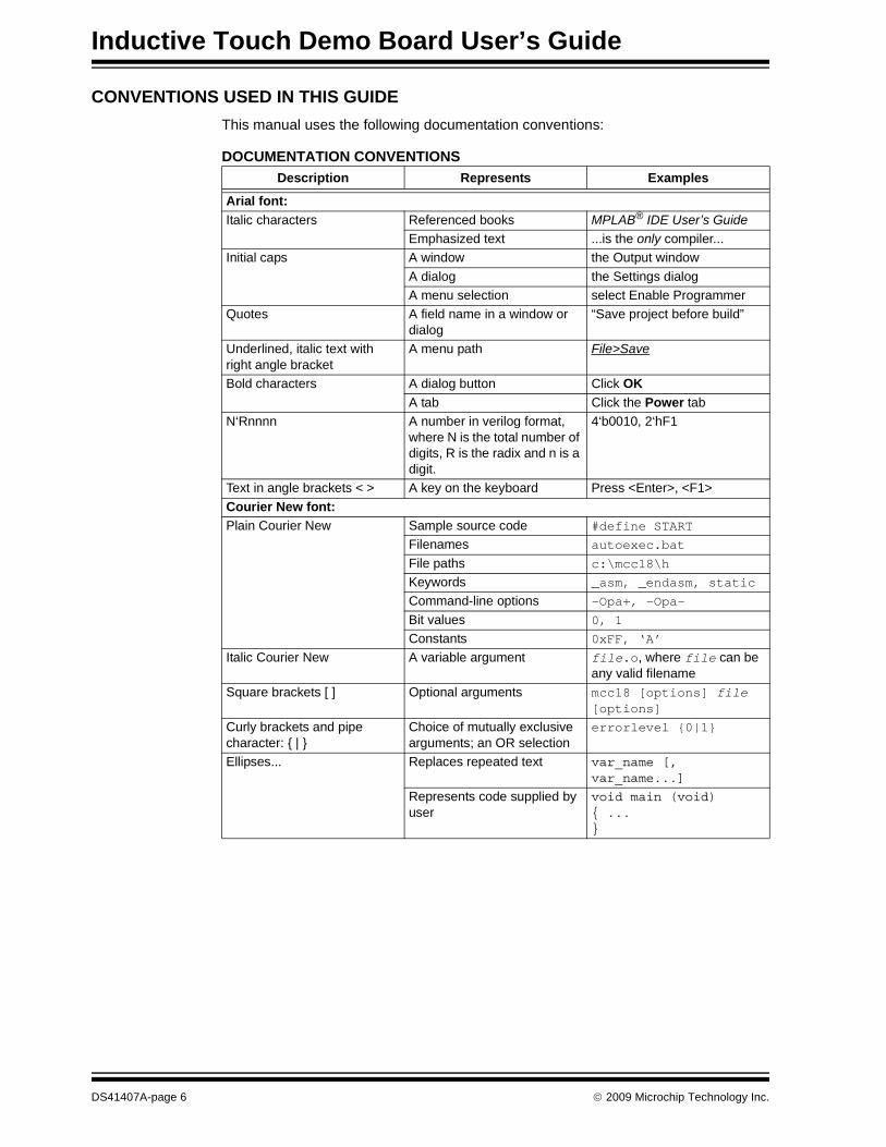
CONVENTIONS USED IN THIS GUIDEThis manual uses the following documentation conventions:
DOCUMENTATION CONVENTIONSDescription Represents Examples
Arial font:Italic characters Referenced books MPLAB® IDE User’s Guide
Emphasized text ...is the only compiler...Initial caps A window the Output window
A dialog the Settings dialogA menu selection select Enable Programmer
Quotes A field name in a window or dialog
“Save project before build”
Underlined, italic text with right angle bracket
A menu path File>Save
Bold characters A dialog button Click OKA tab Click the Power tab
N‘Rnnnn A number in verilog format, where N is the total number of digits, R is the radix and n is a digit.
4‘b0010, 2‘hF1
Text in angle brackets < > A key on the keyboard Press <Enter>, <F1>Courier New font:Plain Courier New Sample source code #define START
Filenames autoexec.bat
File paths c:\mcc18\hKeywords _asm, _endasm, staticCommand-line options -Opa+, -Opa-
Bit values 0, 1Constants 0xFF, ‘A’
Italic Courier New A variable argument file.o, where file can be any valid filename
Square brackets [ ] Optional arguments mcc18 [options] file [options]
Curly brackets and pipe character: { | }
Choice of mutually exclusive arguments; an OR selection
errorlevel {0|1}
Ellipses... Replaces repeated text var_name [, var_name...]
Represents code supplied by user
void main (void){ ...}
DS41407A-page 6 © 2009 Microchip Technology Inc.
Preface
WARRANTY REGISTRATIONPlease complete the enclosed Warranty Registration Card and mail it promptly. Sending in the Warranty Registration Card entitles users to receive new product updates. Interim software releases are available at the Microchip web site.
RECOMMENDED READINGThis user’s guide describes how to use Inductive Touch Demo Board. Other useful doc-uments are listed below. The following Microchip documents are available and recom-mended as supplemental reference resources.Readme for Inductive Touch Demo BoardFor the latest information on using Inductive Touch Demo Board, read the “Readme for Inductive Touch Demo Board.txt” file (an ASCII text file) in the Readmes subdirectory of the MPLAB IDE installation directory. The Readme file contains update information and known issues that may not be included in this user’s guide.Readme FilesFor the latest information on using other tools, read the tool-specific Readme files in the Readmes subdirectory of the MPLAB IDE installation directory. The Readme files contain update information and known issues that may not be included in this user’s guide.
Reference DocumentsReference documents may be obtained by contacting your nearest Microchip sales office (listed in the back of this document) or by downloading via the Microchip web site (www.microchip.com). Recommended documents include:• Individual data sheets and reference manuals:
- PIC16F1936 Data Sheet (DS41364)- MPLAB® IDE Simulator, Editor User’s Guide (DS51025)- MPASM™ Assembler, MPLINK™ Object Linker, MPLIB™ Object Librarian
User’s Guide (DS33014)- MPLAB REAL ICE™ In-Circuit Emulator User’s Guide (DS51616)- PICkit™ Serial Analyzer User’s Guide (DS51647)- mTouch™ Sensing Solution User’s Guide (DS41328)- PICkit™ 3 Programmer/Debugger User’s Guide (DS51795)- MPLAB® ICD 3 In-Circuit Debugger User’s Guide (DS51766)
© 2009 Microchip Technology Inc. DS41407A-page 7
Inductive Touch Demo Board User’s Guide
THE MICROCHIP WEB SITEMicrochip provides online support via our web site at www.microchip.com. This web site is used as a means to make files and information easily available to customers. Accessible by using your favorite Internet browser, the web site contains the following information:• Product Support – Data sheets and errata, application notes and sample
programs, design resources, user’s guides and hardware support documents, latest software releases and archived software
• General Technical Support – Frequently Asked Questions (FAQs), technical support requests, online discussion groups, Microchip consultant program member listing
• Business of Microchip – Product selector and ordering guides, latest Microchip press releases, listing of seminars and events, listings of Microchip sales offices, distributors and factory representatives
DEVELOPMENT SYSTEMS CUSTOMER CHANGE NOTIFICATION SERVICEMicrochip’s customer notification service helps keep customers current on Microchip products. Subscribers will receive e-mail notification whenever there are changes, updates, revisions or errata related to a specified product family or development tool of interest.To register, access the Microchip web site at www.microchip.com, click on Customer Change Notification and follow the registration instructions.The Development Systems product group categories are:• Compilers – The latest information on Microchip C compilers and other language
tools. These include the MPLAB C18 and MPLAB C30 C compilers; MPASM™ and MPLAB ASM30 assemblers; MPLINK™ and MPLAB LINK30 object linkers; and MPLIB™ and MPLAB LIB30 object librarians.
• Emulators – The latest information on Microchip in-circuit emulators.This includes the PICkit 3, MPLAB ICD 3, and MPLAB REAL ICE™.
• MPLAB® IDE – The latest information on Microchip MPLAB IDE, the Windows® Integrated Development Environment for development systems tools. This list is focused on the MPLAB IDE, MPLAB SIM simulator, MPLAB IDE Project Manager and general editing and debugging features.
DS41407A-page 8 © 2009 Microchip Technology Inc.

Preface
CUSTOMER SUPPORTUsers of Microchip products can receive assistance through several channels:• Distributor or Representative• Local Sales Office• Field Application Engineer (FAE)• Technical SupportCustomers should contact their distributor, representative or field application engineer (FAE) for support. Local sales offices are also available to help customers. A listing of sales offices and locations is included in the back of this document.Technical support is available through the web site at: http://support.microchip.com
DOCUMENT REVISION HISTORY
Revision A (November 2009)• Initial Release of this Document.
© 2009 Microchip Technology Inc. DS41407A-page 9

Inductive Touch Demo Board User’s Guide
NOTES:
DS41407A-page 10 © 2009 Microchip Technology Inc.
INDUCTIVE TOUCH DEMO BOARDUSER’S GUIDE
Chapter 1. Introduction
1.1 INTRODUCTIONThank you for purchasing the mTouch™ Inductive Touch demonstration board from Microchip Technology Incorporated. The mTouch Inductive Touch is a simple board that demonstrates the capabilities of Microchip’s Inductive Touch Technology.The Inductive Touch Demo Board can be used stand-alone or with an in-circuit debugger (for example, MPLAB® ICE). The demo board can also be used with the PICkit™ Serial and the mTouch GUI.
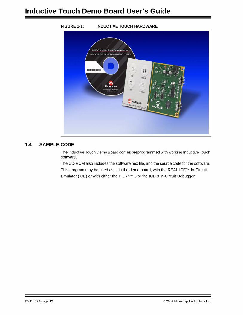
1.2 DEVELOPMENT KIT CONTENTSThe Inductive Touch Demo Board comes with the following:• Inductive Touch demonstration board (Figure 1-1)• CD-ROM that contains:
- Sample code- Source files- Inductive Touch Demo Board User’s Guide- Application Notes
If you are missing any part of the kit, please contact your nearest Microchip sales office listed in the back of this publication for help.
1.3 INDUCTIVE TOUCH DEMONSTRATION BOARDThe Inductive Touch demonstration board has the following hardware features:• 4 touch sensor buttons• 4 indicator LEDs• Variable frequency tone generator• 5V power supply• ICSP™ header• PICkit™ Serial header
© 2009 Microchip Technology Inc. DS41407A-page 11
Inductive Touch Demo Board User’s Guide
FIGURE 1-1: INDUCTIVE TOUCH HARDWARE
1.4 SAMPLE CODEThe Inductive Touch Demo Board comes preprogrammed with working Inductive Touch software.The CD-ROM also includes the software hex file, and the source code for the software. This program may be used as-is in the demo board, with the REAL ICE™ In-Circuit Emulator (ICE) or with either the PICkit™ 3 or the ICD 3 In-Circuit Debugger.
DS41407A-page 12 © 2009 Microchip Technology Inc.
INDUCTIVE TOUCH DEMO BOARDUSER’S GUIDE
Chapter 2. Getting Started
The Inductive Touch Demonstration Board may be used as a stand-alone board, with an in-circuit emulator (for example, MPLAB® REAL ICE™) or with the PICkit™ Serial and the mTouch GUI.
2.1 INDUCTIVE TOUCH DEMO BOARD AS A STAND-ALONE BOARD –PREPROGRAMMED DEVICE
The Inductive Touch Demonstration Board may be demonstrated immediately by following the steps listed below:• Apply power to the Inductive Touch Demo Board. For information on acceptable
power sources, see Appendix A.• Apply pressure to any of the 4 buttons, the associated LED should light, and a
tone should sound.To reprogram the demo board microcontroller, the following will be necessary:• Program source code – user source code may be used to program the device, or
if this previously has been done, the sample program may be restored from the file on the included CD-ROM.
• A compiler, such as the HITECH C® compiler, or equivalent third party compiler, must be used to compile the source code into a hex file before it can be programmed into the device.Other compilers may be used. For a list of these PIC® MCU compatible language tools, see the Microchip web site (www.microcip.com).Once the sample program is in hex file format, a programmer can program the Flash device.
• A device programmer, such as PICkit 3, MPLAB® ICD 3, or REAL ICE™ (programmer functionality available with MPLAB® IDE v8.40 or greater)If the code protection bit(s) have not been programmed, the on-chip program memory can be read out for verification purposes.
2.2 INDUCTIVE TOUCH DEMO BOARD USED WITH AN IN-CIRCUIT DEBUGGERTo use the Inductive Touch Demonstration Board with an In-Circuit Debugger (ICD), refer to the tool’s user guide for instructions to learn how to:• Power-up and configure the ICD• Connect to target boards (such as in Figure 2-1)• Program and debug the microcontroller on the demo board.
© 2009 Microchip Technology Inc. DS41407A-page 13

Inductive Touch Demo Board User’s Guide
FIGURE 2-1: INDUCTIVE TOUCH DEMO BOARD CONNECTED TO PICkit™3 USING USB
2.3 INDUCTIVE TOUCH DEMO BOARD CONNECTION TO THE mTOUCH™ GUIThe Inductive Touch Demonstration Board can be used with the mTouch GUI to demonstrate the operation of the system.• Connect the Inductive Touch Demonstration Board to a PICkit™ Serial Analyzer
as shown in Figure 2-2.
FIGURE 2-2: CONNECTION TO A PICkit™ SERIAL ANALYZER
• Apply power to the Inductive Touch Demonstration Board. For information on acceptable power sources, see Appendix A. “System Detail”.
DS41407A-page 14 © 2009 Microchip Technology Inc.

Getting Started
In MPLAB (version 8.4 or later), select the mTouch Diagnostic Tool under the Tools menu (as shown in Figure 2-3).
FIGURE 2-3: mTOUCH DIAGNOSTIC TOOL
When the Diagnostic Tool is loaded, select the Settings tab to access the tool configuration menu (Figure 2-4).
FIGURE 2-4: SETTINGS
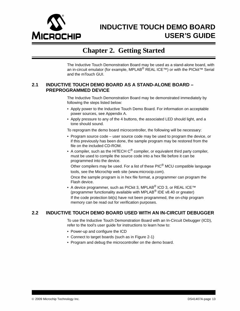
Under the Settings menu select the Custom option (Figure 2-5).
© 2009 Microchip Technology Inc. DS41407A-page 15
Inductive Touch Demo Board User’s Guide
FIGURE 2-5: SELECT BOARD
DS41407A-page 16 © 2009 Microchip Technology Inc.
Getting Started
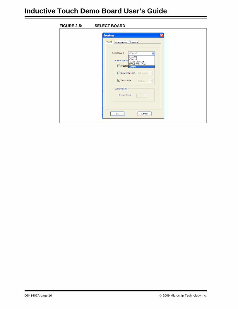
Under the Communication tab, select the I2C option and enter an address of 42 (Figure 2-6).
FIGURE 2-6: COMMUNICATION
The Diagnostic Tool should now display the readings for the first 4 sensors on the display (Figure 2-7).
FIGURE 2-7: FIRST 4 SENSORS READINGS
For more information concerning the diagnostic tools, please check the Microchip web page at www.microchip.com and the MPLAB help files.
© 2009 Microchip Technology Inc. DS41407A-page 17

Inductive Touch Demo Board User’s Guide
NOTES:
DS41407A-page 18 © 2009 Microchip Technology Inc.
INDUCTIVE TOUCH DEMO BOARDUSER’S GUIDE
Chapter 3. Theory of Operation
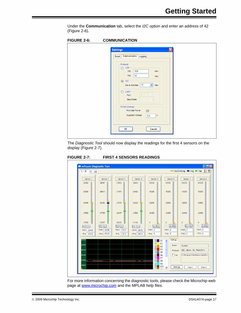
An Inductive Touch system uses the magnetic coupling between a solid metal target and an inductive sensing coil. If a user presses on the front panel, then the coupling between the target and sense coil will increase due to the minute shift in the target’s position toward the sensor coil, as shown in Figure 3-1. The result is a change in the impedance of the sensing coil.
FIGURE 3-1: CROSS SECTION OF AN INDUCTIVE TOUCH SENSOR
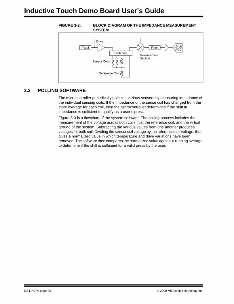
3.1 SENSOR COIL IMPEDANCE MEASUREMENT SYSTEMTo sense this change in the inductive sensing coil, an impedance measurement system and a microcontroller are required. The impedance measurement system operates by exciting the sensor coil with a pulsed current. This produces a pulsed voltage across the coil that is proportional to both the current and the impedance of the coil. The impedance measurement system then converts the pulsed voltage into a DC voltage proportional to the amplitude of the pulsed voltage using a frequency mixer, low pass filter, and amplifier. The resulting DC value is converted to a binary number using an ADC. To assist in maintaining consistency in the readings, a reference coil has been added to remove variations in the readings due to long term variations in the current and due to temperature shifts. The reference coil is in series with the sensor coil, and is measured as part of the conversion process. The resulting value for the reference coil is divided into the sensor coil, resulting in a “normalized value” for the coil. By using the impedance ratio of the two coils, any variation in the impedances due to temperature or long term drive current variation fall out and we are left with a temperature and voltage compensated value. Figure 3-2 shows a block diagram of a typical impedance measurement system.
© 2009 Microchip Technology Inc. DS41407A-page 19
Inductive Touch Demo Board User’s Guide
FIGURE 3-2: BLOCK DIAGRAM OF THE IMPEDANCE MEASUREMENT SYSTEM
3.2 POLLING SOFTWAREThe microcontroller periodically polls the various sensors by measuring impedance of the individual sensing coils. If the impedance of the sense coil has changed from the store average for each coil, then the microcontroller determines if the shift in impedance is sufficient to qualify as a user’s press. Figure 3-3 is a flowchart of the system software. The polling process includes the measurement of the voltage across both coils, just the reference coil, and the virtual ground of the system. Subtracting the various values from one another produces voltages for both coil. Dividing the sensor coil voltage by the reference coil voltage, then gives a normalized value in which temperature and drive variations have been removed. The software then compares the normalized value against a running average to determine if the shift is sufficient for a valid press by the user.
PWM
Driver
Switching
Filter
MeasurementSection
10-bitADC
Sensor Coils
Reference Coil
DS41407A-page 20 © 2009 Microchip Technology Inc.

Theory of Operation
FIGURE 3-3: SYSTEM FLOWCHART
Turn off Driver
Calculate Normalized
Value
Value < Threshold
Get ADC
Select Sensor Input
Yes
Select Reference
Input
Turn on Driver
Button Pressed
LogicAverage New Value
Get ADC
Get ADC
No
© 2009 Microchip Technology Inc. DS41407A-page 21
Inductive Touch Demo Board User’s Guide
NOTES:
DS41407A-page 22 © 2009 Microchip Technology Inc.
INDUCTIVE TOUCH DEMO BOARDUSER’S GUIDE
Appendix A. System Detail
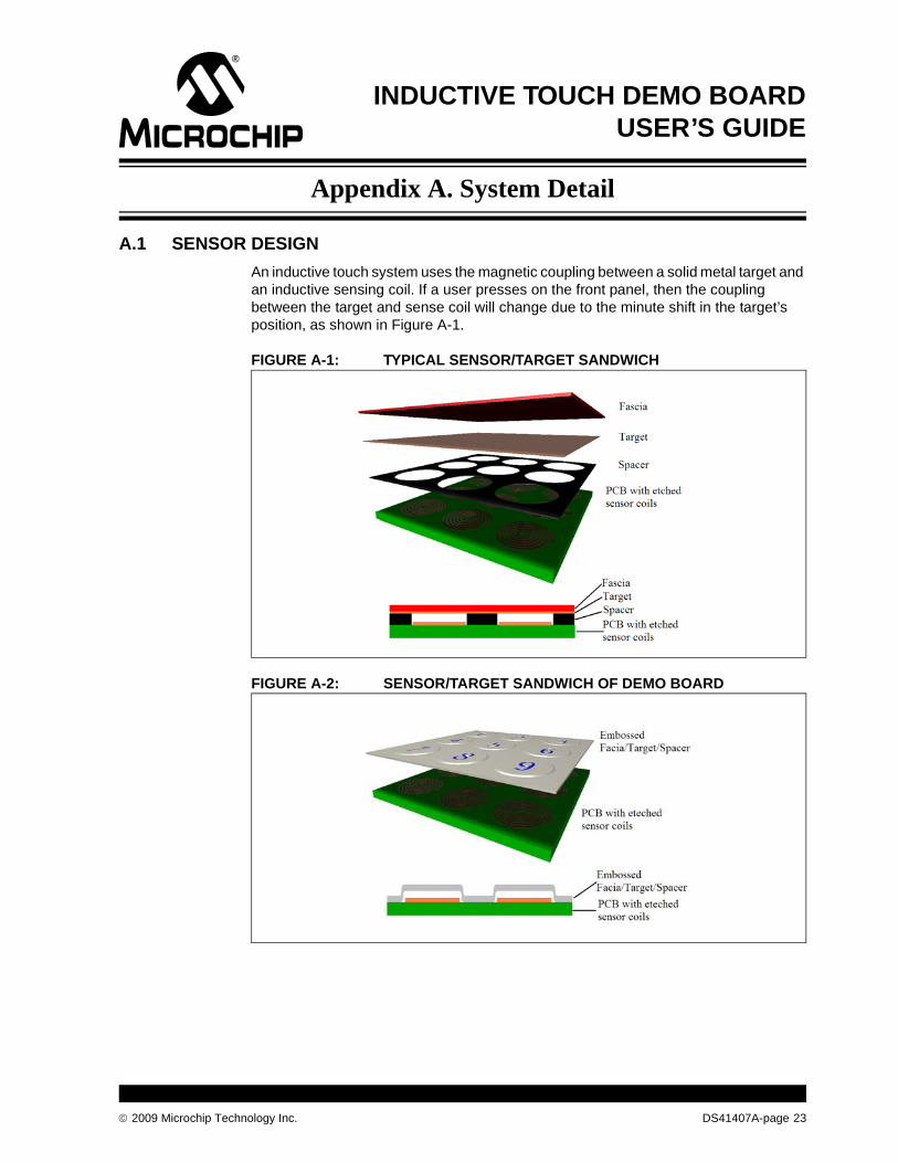
A.1 SENSOR DESIGNAn inductive touch system uses the magnetic coupling between a solid metal target and an inductive sensing coil. If a user presses on the front panel, then the coupling between the target and sense coil will change due to the minute shift in the target’s position, as shown in Figure A-1.
FIGURE A-1: TYPICAL SENSOR/TARGET SANDWICH
FIGURE A-2: SENSOR/TARGET SANDWICH OF DEMO BOARD
© 2009 Microchip Technology Inc. DS41407A-page 23
Inductive Touch Demo Board User’s Guide
A.1.1 FasciaThe fascia is typically the top layer of the sensor sandwich. It is the plastic panel or metal sheet that the user presses on and usually carries the labeling that identifies the button’s location and function. The fascia can also be combined with the target if it is conductive, and can be sufficiently deformed by the user’s press to cause the required minimum change in inductance (the Inductive Touch Demo Board uses a combined Fascia and Target). The material of the fascia can, in theory, be made from any material – so long as it elastically deforms under the range of expected pressures that will be applied by the user.The fascia used in the Inductive Touch Demo Board is 0.018 inches thick aluminum. With a button diameter of 0.8 inches, that means a press force of only 5½ oz. is required to generate the minimum deflection required for a user press.Other common fascia constructions include plastic injection moldings, plastic sheet, sheet or formed metal. Other materials can also be used by the user, provided they elastically deform under pressure.
A.1.2 TargetsThe target is a passive, electrically conductive layer which is arranged to displace or deform along the measurement axis relative to the coil. If a separate fascia layer is used, then the target is mechanically bonded to the fascia, so it will deform with pressure on the fascia. While magnetically permeable materials such as ferrites can be used for the target, highly conductive materials are preferable, due to their good conductivity and lower cost. In a typical application, the target is made from a copper lamination, but it could also be made from any other highly conductive materials such as aluminum, gold, silver or steel. The target layer in the Inductive Touch Demo Board is aluminum, and approximately 0.018 inches thick.Only a thin layer of conductive material is actually required for a target (typically <100 microns) and can be produced, for example, using 3 ounce copper cladding on a PCB substrate. The diameter target should be the same size and shape as the coil.
A.1.3 Spacer Most – but not all – inductive touch constructions use a spacer layer to provide the separation between the target and the coils. Constructions which use an injection molded fascia do not typically require a spacer layer since the separation distance can be molded as an integral feature of the plastic. A spacer layer can also be built into the target layer through embossing (creating a raised ‘bump’ in the target material). The embossed area of the target (immediately above the sensor coil) provides the necessary displacement that will allow the target to move. The thickness of the spacer should be approximately 1%-3% of the diameter of the coil. The spacer layer can be made from a wide range of materials but should be a mechanically stiff and electrically insulating material such as FR4, FR2, resin bonded paper, ABS or other plastic. The depth of embossing on the Inductive Touch Demo Board is approximately 0.010 inch for a 0.8 inch diameter button, or approximately 1.2%.
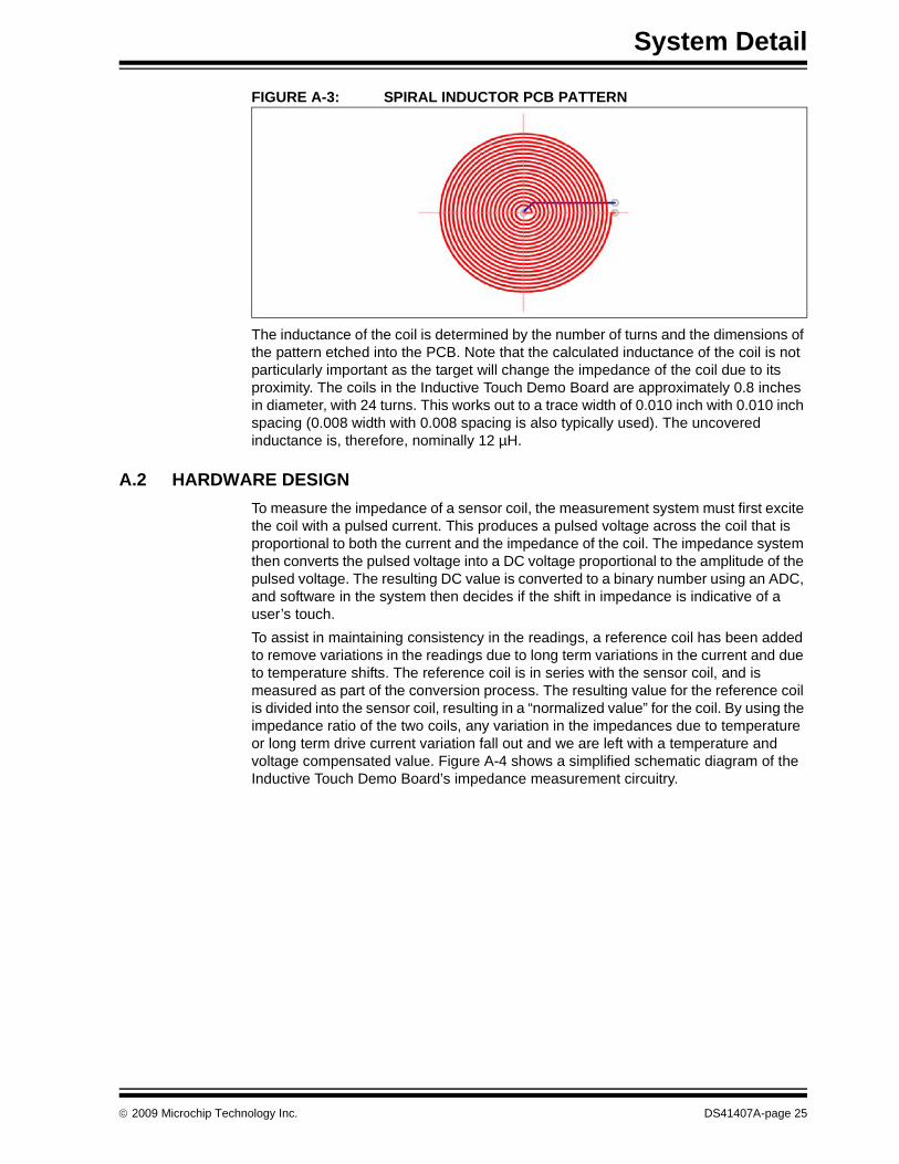
A.1.4 Sensor CoilsThe sensor coils are one or more inductors, preferably implemented as flat spiral coils, etched into the copper layer of a PCB, as shown in Figure A-3.
DS41407A-page 24 © 2009 Microchip Technology Inc.
System Detail
FIGURE A-3: SPIRAL INDUCTOR PCB PATTERN
The inductance of the coil is determined by the number of turns and the dimensions of the pattern etched into the PCB. Note that the calculated inductance of the coil is not particularly important as the target will change the impedance of the coil due to its proximity. The coils in the Inductive Touch Demo Board are approximately 0.8 inches in diameter, with 24 turns. This works out to a trace width of 0.010 inch with 0.010 inch spacing (0.008 width with 0.008 spacing is also typically used). The uncovered inductance is, therefore, nominally 12 µH.
A.2 HARDWARE DESIGNTo measure the impedance of a sensor coil, the measurement system must first excite the coil with a pulsed current. This produces a pulsed voltage across the coil that is proportional to both the current and the impedance of the coil. The impedance system then converts the pulsed voltage into a DC voltage proportional to the amplitude of the pulsed voltage. The resulting DC value is converted to a binary number using an ADC, and software in the system then decides if the shift in impedance is indicative of a user’s touch.To assist in maintaining consistency in the readings, a reference coil has been added to remove variations in the readings due to long term variations in the current and due to temperature shifts. The reference coil is in series with the sensor coil, and is measured as part of the conversion process. The resulting value for the reference coil is divided into the sensor coil, resulting in a “normalized value” for the coil. By using the impedance ratio of the two coils, any variation in the impedances due to temperature or long term drive current variation fall out and we are left with a temperature and voltage compensated value. Figure A-4 shows a simplified schematic diagram of the Inductive Touch Demo Board’s impedance measurement circuitry.
© 2009 Microchip Technology Inc. DS41407A-page 25

Inductive Touch Demo Board User’s Guide
FIGURE A-4: SIMPLIFIED MEASUREMENT CIRCUITRY
The first section of the design is the current driver, shown in Figure A-5.
FIGURE A-5: CURRENT DRIVER CIRCUIT
R1 and C1 form a low pass filter which rounds off the edges of the PWM square wave, to produce a more sine-like waveform for driving the coil. In the Inductive Touch Demo Board, R1 is 1K and C1 is 150pF, this puts the corner frequency at 1MHz which is the frequency of the PWM drive. The next section of the design is the switching circuitry for selecting individual sensor coils. Figure A-6 shows the section of the design.
PWMR1
10
C1 0
optional
VDD
1nF1µF
GPIOLR
LS1 LS2 LS3
GPIO
10-bitADC
GPIOC2
.01µF
.01µF
1K 1K
330PF
330PF
Ref coil/Btn coil
Isolate/Connect
R5R4
R4
R5 C2 10KVDD
10K
10K 1nFMCP6001
MCP6001
PWMR1
10
C1 0
optional
VDD
1nF1µF
DS41407A-page 26 © 2009 Microchip Technology Inc.
System Detail
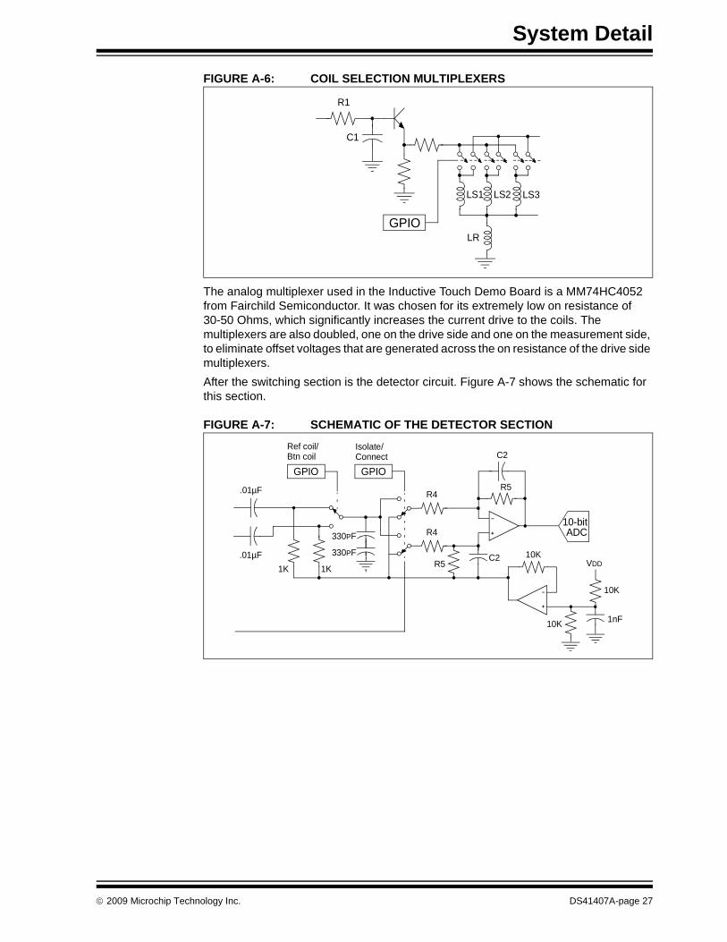
FIGURE A-6: COIL SELECTION MULTIPLEXERS
The analog multiplexer used in the Inductive Touch Demo Board is a MM74HC4052 from Fairchild Semiconductor. It was chosen for its extremely low on resistance of 30-50 Ohms, which significantly increases the current drive to the coils. The multiplexers are also doubled, one on the drive side and one on the measurement side, to eliminate offset voltages that are generated across the on resistance of the drive side multiplexers.After the switching section is the detector circuit. Figure A-7 shows the schematic for this section.
FIGURE A-7: SCHEMATIC OF THE DETECTOR SECTION
R1
C1
GPIOLR
LS1 LS2 LS3
GPIO
10-bitADC
GPIOC2
.01µF
.01µF
1K 1K
330PF
330PF
Ref coil/Btn coil
Isolate/Connect
R5R4
R4
R5C2 10K
VDD
10K
10K 1nF
© 2009 Microchip Technology Inc. DS41407A-page 27

Inductive Touch Demo Board User’s Guide
The detector operates by switching the filter/amplifier circuit between an inverting and non-inverting configuration, in time with the drive waveform of the coils. This allows the detector to flip the negative side of the waveform, resulting in a positive signal – similar to the output of a full wave rectifier. The capacitors in the feedback path of the amplifier/filter, average out the peaks and valleys to produce a DC level proportional to the AC signal’s amplitude. The detector in the Inductive Touch Demo Board uses parallel combination of 100K and 330 pF to place the corner frequency at 5 kHz. With a value of 10K for R4, this also gives a gain of 10 for the system.The multiplexer used for multiplexing the button/reference inputs, and the switching of the amplifier is an MM74HC4053, also from Fairchild. The second op amp at the bottom of the diagram provides a virtual ground at VDD/2 for the single supply circuit. In the demo board, both amps are part of an MCP6002 op amp device.The detector also uses two inputs from the microcontroller to control which waveforms are detected. The first selects between the button coil and the reference coil. The second, disables the multiplexer in the detector, to isolate the detector from the sensor coils. This is necessary to obtain a clean measurement of the detector VDD/2 virtual ground. All three measurements are required to convert the button coil impedance into a normalized value in the software.
A.3 POWER SUPPLYThe power supply of the Inductive Touch Demo Board requires a 9 VDC source, capable of supplying a minimum of 50 mA. Power is supplied to the demo board through a barrel connector at the top right corner of the board. Any standard Microchip 9 VDC power supply will work, which has the appropriate mating connector.
DS41407A-page 28 © 2009 Microchip Technology Inc.
System Detail
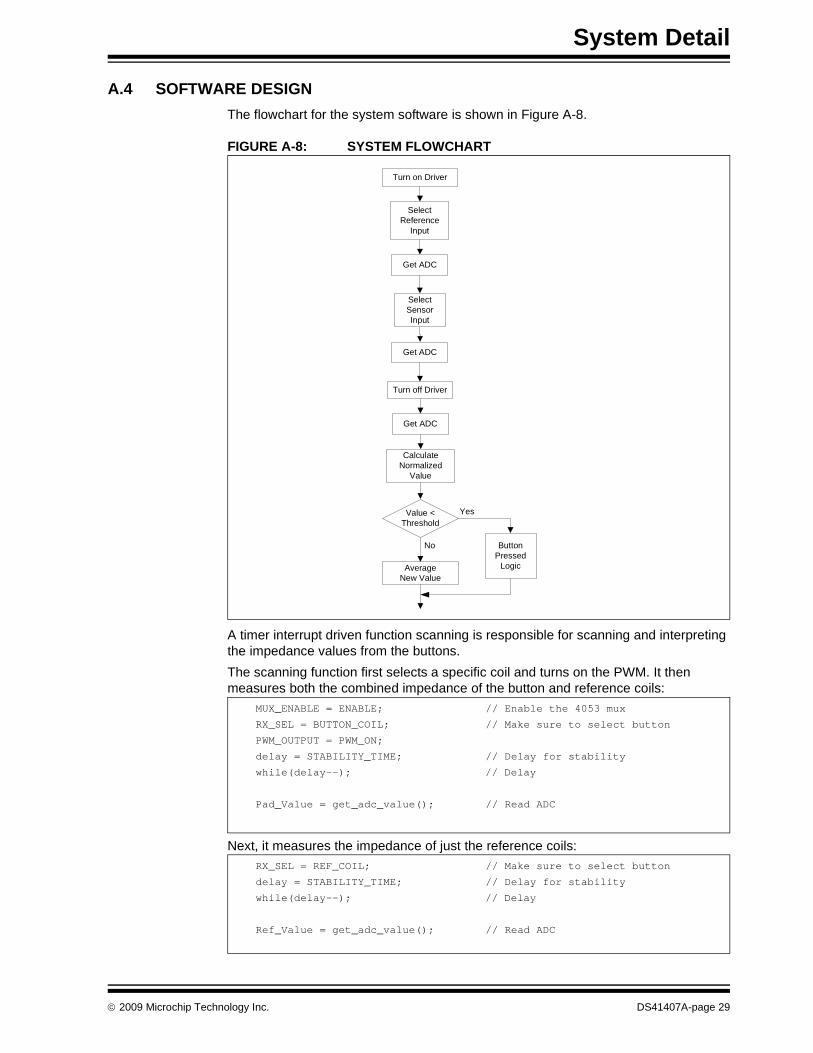
A.4 SOFTWARE DESIGNThe flowchart for the system software is shown in Figure A-8.
FIGURE A-8: SYSTEM FLOWCHART
A timer interrupt driven function scanning is responsible for scanning and interpreting the impedance values from the buttons. The scanning function first selects a specific coil and turns on the PWM. It then measures both the combined impedance of the button and reference coils:
Next, it measures the impedance of just the reference coils:
Turn off Driver
Calculate Normalized
Value
Value < Threshold
Get ADC
Select Sensor Input
Yes
Select Reference
Input
Turn on Driver
Button Pressed
LogicAverage New Value
Get ADC
Get ADC
No
MUX_ENABLE = ENABLE; // Enable the 4053 mux
RX_SEL = BUTTON_COIL; // Make sure to select button
PWM_OUTPUT = PWM_ON;
delay = STABILITY_TIME; // Delay for stability
while(delay--); // Delay
Pad_Value = get_adc_value(); // Read ADC
RX_SEL = REF_COIL; // Make sure to select button
delay = STABILITY_TIME; // Delay for stability
while(delay--); // Delay
Ref_Value = get_adc_value(); // Read ADC
© 2009 Microchip Technology Inc. DS41407A-page 29

Inductive Touch Demo Board User’s Guide
Then, after turning off the PWM and isolating the detector, it determines a value for the virtual ground of the system:
Using this information, the function then generates a normalized value for the sensor coil:
It then compares the value against a trip threshold based on the coil’s running average and the trip value specified for the coil:
And, finally, it averages the new value into the running average if the button is not pressed:
MUX_ENABLE = NOT_ENABLE; // Enable the 4053 mux
PWM_OUTPUT = PWM_OFF;
delay = STABILITY_TIME; // Delay for stability
while(delay--); // Delay
Vref_Value = get_adc_value(); // Read ADC
pressValue = Pad_Value - Ref_Value; // Get just button value
pressValue <<= 10; // Multiply by 1024
pressValue = pressValue / (Ref_Value - Vref_Value);// Key pad reading
smallAvg = averageData[button]>>4;
threshold = smallAvg - (tripData[button]>>4);
if(pressValue < threshold)
{
_KeyPressed = TRUE; // Set flag for key pressed
}
else if (pressValue >= (threshold - 5))
{
_KeyPressed = FALSE; // Set flag for no key pressed
if (averageCtr[button]++ > AVG_DELAY)
{
averageData[button] -= smallAvg;
averageData[button] += pressValue;
averageCtr[button] = 0;
}
}
DS41407A-page 30 © 2009 Microchip Technology Inc.

System Detail
The actual conversion of a value out of the detector is performed by the get_adc_value(void) function. It performs 4 conversions of each value and adds the results together to obtain a 12-bit value from the 10 bit ADC. This increase in resolution is possible due to the random noise present at the output of the detector.
The main line program then interprets the button press, lights the appropriate LED, and generates the appropriate tone.
A.5 BOARD LAYOUT AND SCHEMATIC
FIGURE A-9: INDUCTIVE TOUCH DEMO BOARD LAYOUT
WORD get_adc_value(void)
{
BYTE Tacq;
BYTE i;
WORD ADC_Val = 0;
DWORD ADC_Avg = 0;
while(ADGO == 1); // Wait until done
for (i=0; i<4; i++) // Do 4 samples and average
{
Tacq = ACQ_TIME; // Wait the needed acq time
while(Tacq--);
ADGO = 1; // Start ADC conversion
while(ADGO == 1); // Wait until done
ADC_Val = (unsigned int)ADRESH<<8; // Read high byte value
ADC_Val |= (unsigned int)ADRESL; // Read high byte value
ADC_Avg += ADC_Val;
}
return((WORD)ADC_Avg); // Return the average value
}
© 2009 Microchip Technology Inc. DS41407A-page 31
Inductive Touch Demo Board User’s Guide
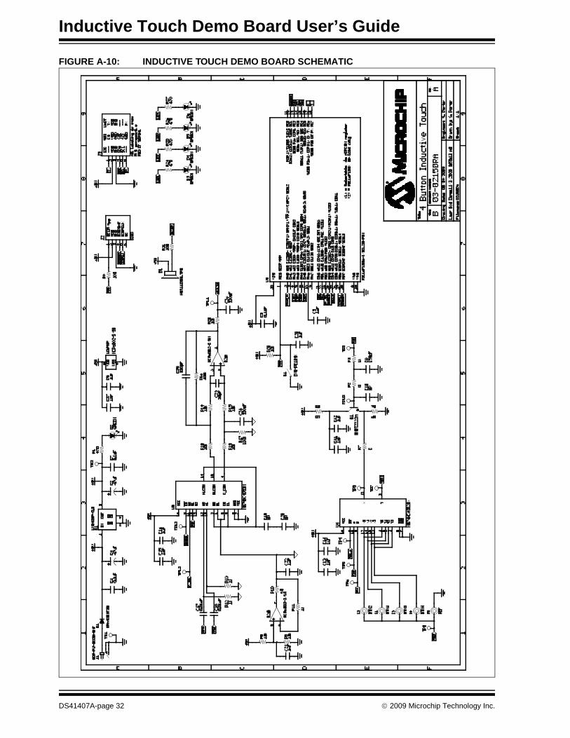
FIGURE A-10: INDUCTIVE TOUCH DEMO BOARD SCHEMATIC
DS41407A-page 32 © 2009 Microchip Technology Inc.
INDUCTIVE TOUCH DEMO BOARDUSER’S GUIDE
Index
Numerics5V power supply ...................................................... 11
CCoil Selection Multiplexers ....................................... 26Communication tab .................................................. 17Customer Notification Service.................................... 8Customer Support ...................................................... 9
DDemonstration Board ..........................................11, 13Documentation
Conventions........................................................ 6Layout ................................................................. 5
FFascia ...................................................................... 23Flash device............................................................. 13
HHardware Design ..................................................... 25
Current Driver Circuit ........................................ 25Schematic of the Detector Section ................... 26Simplified Measurement Circuitry ..................... 25
IIn-Circuit Debugger.................................................. 13Inductive Touch Hardware ....................................... 12Internet Address......................................................... 8Introducing mTouch ................................................. 11
KKit Components ....................................................... 11
MMicrochip Internet Web Site ....................................... 8Microchip sales office............................................... 11MM74HC4052.......................................................... 26MM74HC4053.......................................................... 27MPLAB ICD 2........................................................... 13MPLAB ICE.............................................................. 13mTouch Diagnostic Tool .......................................... 15mTouch GUI............................................................. 13
PPICDEM 2 Plus Kit. See Kit Components.PICkit™ Serial.......................................................... 13Program source code............................................... 13
RReading, Recommended ........................................... 7Readme ..................................................................... 7
SSample code ............................................................ 11Sample Devices ....................................................... 11Sensor Design.......................................................... 23Settings menu .......................................................... 15Software Design....................................................... 28
Reference coils ................................................. 28System Flow Chart............................................ 28
Source files .............................................................. 11System Detail ........................................................... 23
TTool configuration menu........................................... 15Typical Sensor/Target Sandwich ............................. 23
WWarranty Registration ................................................ 7WWW Address........................................................... 8
© 2009 Microchip Technology Inc. DS41407A-page 33

DS41407A-page 34 © 2009 Microchip Technology Inc.
AMERICASCorporate Office2355 West Chandler Blvd.Chandler, AZ 85224-6199Tel: 480-792-7200 Fax: 480-792-7277Technical Support: http://support.microchip.comWeb Address: www.microchip.comAtlantaDuluth, GA Tel: 678-957-9614 Fax: 678-957-1455BostonWestborough, MA Tel: 774-760-0087 Fax: 774-760-0088ChicagoItasca, IL Tel: 630-285-0071 Fax: 630-285-0075ClevelandIndependence, OH Tel: 216-447-0464 Fax: 216-447-0643DallasAddison, TX Tel: 972-818-7423 Fax: 972-818-2924DetroitFarmington Hills, MI Tel: 248-538-2250Fax: 248-538-2260KokomoKokomo, IN Tel: 765-864-8360Fax: 765-864-8387Los AngelesMission Viejo, CA Tel: 949-462-9523 Fax: 949-462-9608Santa ClaraSanta Clara, CA Tel: 408-961-6444Fax: 408-961-6445TorontoMississauga, Ontario, CanadaTel: 905-673-0699 Fax: 905-673-6509
ASIA/PACIFICAsia Pacific OfficeSuites 3707-14, 37th FloorTower 6, The GatewayHarbour City, KowloonHong KongTel: 852-2401-1200Fax: 852-2401-3431Australia - SydneyTel: 61-2-9868-6733Fax: 61-2-9868-6755China - BeijingTel: 86-10-8528-2100 Fax: 86-10-8528-2104China - ChengduTel: 86-28-8665-5511Fax: 86-28-8665-7889China - Hong Kong SARTel: 852-2401-1200 Fax: 852-2401-3431China - NanjingTel: 86-25-8473-2460Fax: 86-25-8473-2470China - QingdaoTel: 86-532-8502-7355Fax: 86-532-8502-7205China - ShanghaiTel: 86-21-5407-5533 Fax: 86-21-5407-5066China - ShenyangTel: 86-24-2334-2829Fax: 86-24-2334-2393China - ShenzhenTel: 86-755-8203-2660 Fax: 86-755-8203-1760China - WuhanTel: 86-27-5980-5300Fax: 86-27-5980-5118China - XiamenTel: 86-592-2388138 Fax: 86-592-2388130China - XianTel: 86-29-8833-7252Fax: 86-29-8833-7256China - ZhuhaiTel: 86-756-3210040 Fax: 86-756-3210049
ASIA/PACIFICIndia - BangaloreTel: 91-80-3090-4444 Fax: 91-80-3090-4080India - New DelhiTel: 91-11-4160-8631Fax: 91-11-4160-8632India - PuneTel: 91-20-2566-1512Fax: 91-20-2566-1513Japan - YokohamaTel: 81-45-471- 6166 Fax: 81-45-471-6122Korea - DaeguTel: 82-53-744-4301Fax: 82-53-744-4302Korea - SeoulTel: 82-2-554-7200Fax: 82-2-558-5932 or 82-2-558-5934Malaysia - Kuala LumpurTel: 60-3-6201-9857Fax: 60-3-6201-9859Malaysia - PenangTel: 60-4-227-8870Fax: 60-4-227-4068Philippines - ManilaTel: 63-2-634-9065Fax: 63-2-634-9069SingaporeTel: 65-6334-8870Fax: 65-6334-8850Taiwan - Hsin ChuTel: 886-3-6578-300Fax: 886-3-6578-370Taiwan - KaohsiungTel: 886-7-536-4818Fax: 886-7-536-4803Taiwan - TaipeiTel: 886-2-2500-6610 Fax: 886-2-2508-0102Thailand - BangkokTel: 66-2-694-1351Fax: 66-2-694-1350
EUROPEAustria - WelsTel: 43-7242-2244-39Fax: 43-7242-2244-393Denmark - CopenhagenTel: 45-4450-2828 Fax: 45-4485-2829France - ParisTel: 33-1-69-53-63-20 Fax: 33-1-69-30-90-79Germany - MunichTel: 49-89-627-144-0 Fax: 49-89-627-144-44Italy - Milan Tel: 39-0331-742611 Fax: 39-0331-466781Netherlands - DrunenTel: 31-416-690399 Fax: 31-416-690340Spain - MadridTel: 34-91-708-08-90Fax: 34-91-708-08-91UK - WokinghamTel: 44-118-921-5869Fax: 44-118-921-5820
WORLDWIDE SALES AND SERVICE
03/26/09


