+ All Categories
Home > Technology > Mts t series th-analog_standard_data_sheet

Mts t series th-analog_standard_data_sheet

Date post: 22-Jan-2018
Category:
Upload: electromate
View: 221 times
Download: 0 times
Share this document with a friend
10
TH Analog Data Sheet Temposonics ® Magnetostrictive Linear Position Sensors – ATEX & IECEx certified – Continuous operation under harsh industrial conditions – Flameproof / Increased safety ELECTROMATE Toll Free Phone (877) SERVO98 Toll Free Fax (877) SERV099 www.electromate.com [email protected] Sold & Serviced By:
Transcript

TH AnalogData Sheet

Temposonics®

Magnetostrictive Linear Position Sensors

– ATEX & IECEx certified– Continuous operation under harsh industrial conditions– Flameproof / Increased safety

ELECTROMATEToll Free Phone (877) SERVO98

Toll Free Fax (877) SERV099www.electromate.com

[email protected]

Sold & Serviced By:

Magnet fieldof current pulse

Magnet field of position magnet

Mechanicalstrain pulse

Movable position magnet

Magnetostrictivesensing element(waveguide)

Currentinterrogationpulse

Strain (torsion) pulse converter

Temposonics® TH AnalogData Sheet

MEASURING TECHNOLOGY

For position measurement, the absolute, linear Temposonics® position sensors make use of the properties offered by the specially designed magnetostrictive waveguide. Inside the sensor a torsional strain pulse is induced in the waveguide by momentary interaction of two magnetic fields. The interaction between these two magnetic fields produces a strain pulse, which is detected by the electronics at the head of the sensor. One field is produced by a moving position magnet, which travels along the sensor rod with the waveguide inside. The other field is generated by a current pulse applied to the waveguide. The position of the moving magnet is determined precisely by measuring the time elapsed between the application of the current pulse and the arrival of the strain pulse at the sensor head. The result is a reliable position measurement with high accuracy and repeatability.

Fig. 1: Time-based magnetostrictive position sensing principle

TH SENSOR

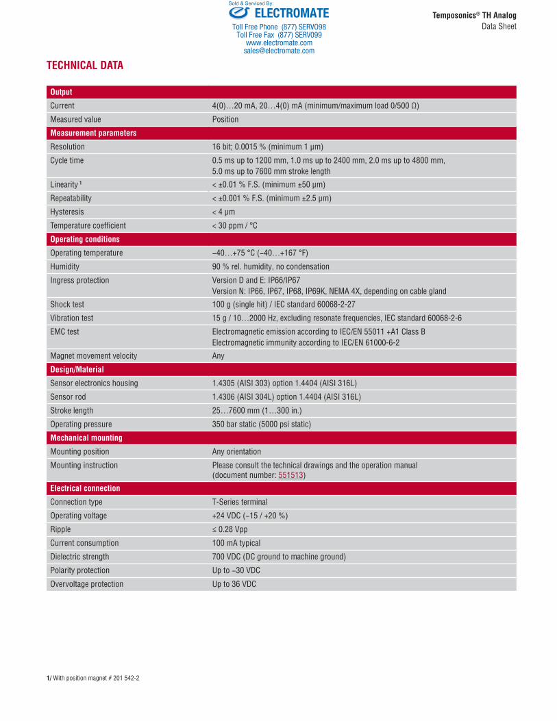
The TH sensor is extremely robust and ideal for continuous operation under harsh industrial conditions. T-Series sensors are ATEX and IECEx certified for hazardous areas in zone 0/1, zone 1, zone 2, zone 21 and zone 22 (flameproof/increased safety). The T-Series is offered in a standard 10 mm (0.39 in.) rod in lengths from 25…7600 mm (1…300 in.) The sensor rod is capable of with-standing high pressures such as those found in hydraulic cylinders. Furthermore the sensor is also suitable for petro chemical plants and caustic environments. The sensor head contains the active signal condi-tioning and a complete integrated electronics interface.

Certification

Version D

Flameproof housing with flameproof connection chamber: IBExU 14 ATEX 1232XIECEx IBE 14.0062X

II 1/2G Ex db IIC T4 Ga/Gb II 1G/2D Ex tb IIIC T130°C Ga/Db

Version E

Flameproof housing with increased safety connection chamber: IBExU 14 ATEX 1232XIECEx IBE 14.0062X

II 1/2G Ex db e IIC T4 Ga/Gb II 1G/2D Ex tb IIIC T130°C Ga/Db

Version N

No hazardous rating: IP66, IP67, IP68, IP69K, NEMA 4X

ELECTROMATEToll Free Phone (877) SERVO98

Toll Free Fax (877) SERV099www.electromate.com

[email protected]

Sold & Serviced By:

Temposonics® TH AnalogData Sheet

TECHNICAL DATA

Output

Current 4(0)…20 mA, 20…4(0) mA (minimum/maximum load 0/500 Ω)

Measured value Position

Measurement parameters

Resolution 16 bit; 0.0015 % (minimum 1 µm)

Cycle time 0.5 ms up to 1200 mm, 1.0 ms up to 2400 mm, 2.0 ms up to 4800 mm, 5.0 ms up to 7600 mm stroke length

Linearity 1 < ±0.01 % F.S. (minimum ±50 µm)

Repeatability < ±0.001 % F.S. (minimum ±2.5 µm)

Hysteresis < 4 µm

Temperature coefficient < 30 ppm / °C

Operating conditions

Operating temperature −40…+75 °C (−40…+167 °F)

Humidity 90 % rel. humidity, no condensation

Ingress protection Version D and E: IP66/IP67Version N: IP66, IP67, IP68, IP69K, NEMA 4X, depending on cable gland

Shock test 100 g (single hit) / IEC standard 60068-2-27

Vibration test 15 g / 10…2000 Hz, excluding resonate frequencies, IEC standard 60068-2-6

EMC test Electromagnetic emission according to IEC/EN 55011 +A1 Class BElectromagnetic immunity according to IEC/EN 61000-6-2

Magnet movement velocity Any

Design/Material

Sensor electronics housing 1.4305 (AISI 303) option 1.4404 (AISI 316L)

Sensor rod 1.4306 (AISI 304L) option 1.4404 (AISI 316L)

Stroke length 25…7600 mm (1…300 in.)

Operating pressure 350 bar static (5000 psi static)

Mechanical mounting

Mounting position Any orientation

Mounting instruction Please consult the technical drawings and the operation manual(document number: 551513)

Electrical connection

Connection type T-Series terminal

Operating voltage +24 VDC (−15 / +20 %)

Ripple ≤ 0.28 Vpp

Current consumption 100 mA typical

Dielectric strength 700 VDC (DC ground to machine ground)

Polarity protection Up to −30 VDC

Overvoltage protection Up to 36 VDC

1/ With position magnet # 201 542-2

ELECTROMATEToll Free Phone (877) SERVO98

Toll Free Fax (877) SERV099www.electromate.com

[email protected]

Sold & Serviced By:

132.5(5.22) 2.5

(0.1)

83.8(3.29)

77

(3.0

3) 55(2

.17)

51(2)

Null zone Stroke length 25…7600

(1…300)

Dead zone63.5 (2.5) / 66 (2.6)*

Refer to “Table 1” for“Flange threads”

* > 5000 (197) stroke length

Sensor electronics housing

Mag

net

Ø 10

± 0

.13

(Ø 0

.39

± 0.

001)

Version D

Version E & N

83.8(3.29)

132.5(5.22)

55(2

.17)

51(2)

Null zone Dead zoneSensor electronics housing

83.8(3.29)

55

(2.1

7)

73

(2.8

7) 7

7(3

.03)

Sensor electronics housing112.5(4.43)

51 63.5 (2.5) /66 (2.6)*(2)

Null zone Stroke length25…7600(1…300)

Stroke length25…7600(1…300)

Dead zone

Refer to “Table 1” for“Flange threads”

Refer to “Table 1” for“Flange threads”

* > 5000 (197) stroke length

* > 5000 (197) stroke length

63.5 (2.5) /66 (2.6)*

Ø 10

± 0

.13

(Ø 0

.39

± 0.

001)

Mag

net

Mag

net

Ø 10

± 0

.13

(Ø 0

.39

± 0.

001)

Version D

83.8(3.29)

132.5(5.22)

55(2

.17)

51(2)

Null zone Dead zoneSensor electronics housing

83.8(3.29)

55

(2.1

7)

73

(2.8

7) 7

7(3

.03)

Sensor electronics housing112.5(4.43)

51 63.5 (2.5) /66 (2.6)*(2)

Null zone Stroke length25…7600(1…300)

Stroke length25…7600(1…300)

Dead zone

Refer to “Table 1” for“Flange threads”

Refer to “Table 1” for“Flange threads”

* > 5000 (197) stroke length

* > 5000 (197) stroke length

63.5 (2.5) /66 (2.6)*

Ø 10

± 0

.13

(Ø 0

.39

± 0.

001)

Mag

net

Mag

net

Ø 10

± 0

.13

(Ø 0

.39

± 0.

001)

With flat-faced flange

Temposonics® TH AnalogData Sheet

TECHNICAL DRAWINGS

(4.43)2.5

(0.1)

83.8(3.29)

73(2

.87) 55

(2.1

7)

51(2)

Null zone

Ø 10

± 0

.13

(Ø 0

.39

± 0.

001)

Stroke length 25…7600(1…300)

Dead zone

Refer to “Table 1” for“Flange threads”

63.5 (2.5) / 66 (2.6)*

* > 5000 (197) stroke length

Sensor electronics housing112.5

Mag

net

Version E & N

Controlling design dimensions are in millimeters and measurements in ( ) are in inchesUnless otherwise stated, apply to the general tolerances according to DIN ISO 2768-m

With raised-face flange

ELECTROMATEToll Free Phone (877) SERVO98

Toll Free Fax (877) SERV099www.electromate.com

[email protected]

Sold & Serviced By:

Mag

net

18 (0.7)

Side connection C01 / N01 / NF1 (with adapter) / M01 (without adapter)

Temposonics® TH AnalogData Sheet

Flange type Description Flange threads

F Flange with flat-face1.4404 (AISI 316L) ¾"-16 UNF-3A

G Flange with raised-face1.4404 (AISI 316L) ¾"-16 UNF-3A

MFlange with flat-face1.4305 (AISI 303)

M18×1.5−6g

N Flange with raised-face 1.4305 (AISI 303) M18×1.5−6g

SFlange with flat-face1.4305 (AISI 303)

¾"-16 UNF-3A

TFlange with raised-face1.4305 (AISI 303)

¾"-16 UNF-3A

W Flange with flat-face1.4404 (AISI 316L) M18×1.5−6g

Table 1: Model TH flange type references

Top connectionTop connection Connection length

Mag

net

18(0.7)

Top connection C10 / N10 (with adapter) / M10 (without adapter)

Controlling design dimensions are in millimeters and measurements in ( ) are in inchesUnless otherwise stated, apply to the general tolerances according to DIN ISO 2768-m

CONNECTION OPTIONS

Connector on 6 different positions at 60° each

Sensor with adapter

Sensor with adapter

ELECTROMATEToll Free Phone (877) SERVO98

Toll Free Fax (877) SERV099www.electromate.com

[email protected]

Sold & Serviced By:

Zone 1 Zone 0

Mag

net

Zone 1 Zone 0

Mag

net

Temposonics® TH AnalogData Sheet

Version D – Flameproof housing with flameproof connection chamber ATEX / IECExEx db / Ex tb

ZONE DIVISION

Version E –Flameproof housing with increased safety connection chamber ATEX / IECExEx db e / Ex tb

NOTICE

Seal sensor according to ingress protection IP67 between zone 0 and zone 1.

ELECTROMATEToll Free Phone (877) SERVO98

Toll Free Fax (877) SERV099www.electromate.com

[email protected]

Sold & Serviced By:

Temposonics® TH AnalogData Sheet

CONNECTOR WIRING

Suitable for connection types: C01, C10, M01, M10, N01, N10 Pin Description

1 Output 1

2 DC Ground

3 Output 2

4 DC Ground

5 +24 VDC (−15 / +20 %)

6 DC Ground (0 V)

7 PE – Protective Earth Ground

Model TH (version E & N) rod-style sensor wiring diagram (1.5 mm2 conductor)External ground lug

External ground lug

External ground lug

External ground lug

External ground lug

External ground lug

Suitable for connection types: C01, C10, N01, N10 Pin Description

1 Output 1

2 DC Ground

3 Output 2

4 DC Ground

5 +24 VDC (−15 / +20 %)

6 DC Ground (0 V)

7 PE – Protective Earth Ground

Model TH (version D) rod-style sensor wiring diagram (2.5 mm2 conductor)

Suitable for connection type: NF1 Pin Description

1 Output

2 DC Ground

3 Output 2

4 +24 VDC (−15 / +20 %)

5 DC Ground (0 V)

6 PE – Protective Earth Ground

Model TH (version E & N) rod-style sensor wiring diagram (2.5 mm2 conductor)

External ground lug

External ground lug

External ground lug

ELECTROMATEToll Free Phone (877) SERVO98

Toll Free Fax (877) SERV099www.electromate.com

[email protected]

Sold & Serviced By:

Temposonics® TH AnalogData Sheet

Position magnets

Ø 32.8(Ø 1.29)

Ø 23.8(Ø 0.94)

Ø 13.5 (Ø 0.53)

Ø 4.3(Ø 0.17)

7.9(0.31)

Ø 25.4(Ø 1)

Ø 13.5(Ø 0.53) 7.9

(0.31)

Ø 32.8(Ø 1.29)

Ø 23.8(Ø 0.94)Ø 13.5

(Ø 0.53)

Ø 4.3(Ø 0.17)

60°

140°

3 (0

.12)

7.9(0.31)

Standard ring magnetPart no. 201 542-2

Material: PA ferrite GF20Weight: Ca. 14 gOperating temperature: −40…+105 °C (−40…+221 °F)Surface pressure: Max. 40 N/mm2

Fastening torque for M4 screws:Max. 1 Nm

Ring magnet OD25,4Part no. 400 533

Material: PA ferriteWeight: Ca. 10 gOperating temperature: −40…+105 °C (−40…+221 °F)Surface pressure: Max. 40 N/mm2

U-magnet OD33Part no. 251 416-2

Material: PA ferrite GF20Weight: Ca. 11 gOperating temperature: −40…+105 °C (−40…+221 °F)Surface pressure: Max. 40 N/mm2

Fastening torque for M4 screws: Max. 1 Nm

Magnet floats 2

Ø 18(Ø 0.7)

Ø 47 (Ø 1.85)

77

(3.0

1)

Ø 18 (Ø 0.7)

57

(2.2

2)

Ø 59 (Ø 2.32)

Ø 18 (Ø 0.7)

36

(1.4

)

Ø 41 (Ø 1.61)

Ø 18 (Ø 0.7)

Ø 89 (Ø 3.5)

91

(3.5

7)

Magnet floatPart no. 251 981-2

Pressure: 29.3 bar (425 psi)Operating temperature: −40…125 °C (−40…257 °F) Magnet offset: No Specific gravity: 0.67Material: Stainless steelWeight offset: Yes

Magnet floatPart no. 251 387-2

Pressure: 22.4 bar (325 psi)Operating temperature: −40…125 °C (−40…257 °F) Magnet offset: NoSpecific gravity: 0.48Material: Stainless steelWeight offset: Yes

Magnet floatPart no. 200 938-2

Pressure: 8.6 bar (125 psi)Operating temperature: −40…125 °C (−40…257 °F) Magnet offset: NoSpecific gravity: 0.74Material: Stainless steelWeight offset: Yes

Magnet floatPart no. 251 469-2

Pressure: 29.3 bar (425 psi)Operating temperature: −40…125 °C (−40…257 °F) Magnet offset: NoSpecific gravity: 0.45Material: Stainless steelWeight offset: Yes

2/ – Be sure that the float specific gravity is at least 0.05 less than that of the measured liquid as a safety margin at ambient temperature. – For interface measurement: A minimum of 0.05 specific gravity differential is required between the upper and lower liquids.

– When the magnet is not shown, the magnet is positioned at the center line of float.– An offset weight is installed in the float to bias or tilt the float installed on the sensor tube. So the float remains in contact with the sensor tube at all times and guarantees permanent potential equalization of the float. The offset is required for installations that must conform to ATEX standards.

Controlling design dimensions are in millimeters and measurements in ( ) are in inches

FREQUENTLY ORDERED ACCESSORIES – Additional options available in our Accessories Guide 551444

ELECTROMATEToll Free Phone (877) SERVO98

Toll Free Fax (877) SERV099www.electromate.com

[email protected]

Sold & Serviced By:

Temposonics® TH AnalogData Sheet

Magnet floats 3 Standard interface floats 3

Ø 18 (0.7)

50

(1.9

6)

Ø 47(1.83)

54

(2.1

1)

Ø 18 (Ø 0.7)

31

(1.2

2)

27

(1.0

6)

Ø 47

(Ø 1.83)

Ø 18 (Ø 0.7)

Ø 47 (Ø 1.85)

77

(3.0

1)

Ø 18 (Ø 0.7)

Ø 47 (Ø 1.85)

77

(3.0

1)

Magnet float 4

Part no. 201 605-2

Pressure: 4 bar (60 psi)Operating temperature: −40…125 °C (−40…257 °F) Magnet offset: YesSpecific gravity: 0.6Material: Stainless steelWeight offset: Yes

Magnet float 4

Part no. 201 606-2

Pressure: 4 bar (60 psi)Operating temperature: −40…125 °C (−40…257 °F) Magnet offset: YesSpecific gravity: 0.93Material: Stainless steelWeight offset: Yes

Magnet floatPart no. 251 982-2

Pressure: 29.3 bar (425 psi)Operating temperature: −40…125 °C (−40…257 °F) Magnet offset: NoSpecific gravity: 0.90…0.96Material: Stainless steelWeight offset: Yes

Magnet floatPart no. 251 983-2

Pressure: 29.3 bar (425 psi)Operating temperature: −40…125 °C (−40…257 °F) Magnet offset: NoSpecific gravity: 1.03…1.10Material: Stainless steelWeight offset: Yes

Collar Programming tools

Ø 27 (Ø 1.06) Ø 10

(Ø 0.39) 5

(0.2)

8-32 threads

4 (0.16)

8(0.31)

9 (0.35)

CollarPart no. 560 777

Material: Stainless steel 1.4301(AISI 304)Weight: Ca. 30 g

Hex key 7⁄64 required

Analog hand programmer Part no. 253 124

Easy teach-in-setups of stroke length and direction on desired zero/span positions. For the first output.

Programming kitPart no. EU: 253 134-1Part no. US: 253 309-1

Kit includes: Interface converter box,power supply, cableSoftware is available at: www.mtssensors.com

Analog cabinet programmer Part no. 253 408

Features snap-in mounting on stan-dard 35 mm DIN rail. This program-mer can be permanently mounted in a control cabinet and includes a program/run switch. For the first output.

3/ – Be sure that the float specific gravity is at least 0.05 less than that of the measured liquid as a safety margin at ambient temperature. – For interface measurement: A minimum of 0.05 specific gravity differential is required between the upper and lower liquids. – When the magnet is not shown, the magnet is positioned at the center line of float.

– An offset weight is installed in the float to bias or tilt the float installed on the sensor tube. So the float remains in contact with the sensor tube at all times and guarantees permanent potential equalization of the float. The offset is required for installations that must conform to ATEX standards.4/ Standard float that can be expedited.

Controlling design dimensions are in millimeters and measurements in ( ) are in inches

ELECTROMATEToll Free Phone (877) SERVO98

Toll Free Fax (877) SERV099www.electromate.com

[email protected]

Sold & Serviced By:

Standard stroke length (mm)*

Stroke length Ordering steps

25 … 500 mm 5 mm

500 … 750 mm 10 mm

750…1000 mm 25 mm

1000…2500 mm 50 mm

2500…5000 mm 100 mm

5000…7600 mm 250 mm

Standard stroke length (in.)*

Stroke length Ordering steps

1 … 20 in. 0.2 in.

20 … 30 in. 0.4 in.

30 … 40 in. 1.0 in.

40…100 in. 2.0 in.

100…200 in. 4.0 in.

200…300 in. 10.0 in.

Temposonics® TH AnalogData Sheet

T H 1 N N

a b c d e f g h i

a Sensor model

T H Hydraulic rod style

b Design

Model TH rod-style sensor with housing 1.4305 (AISI 303) (hydraulic rod style, material 1.4306 (AISI 304L))

M Flange with flat-face (M18×1.5−6g)

N Flange with raised-face (M18×1.5−6g)

S Flange with flat-face (¾"-16 UNF-3A)

T Flange with raised-face (¾"-16 UNF-3A)

Model TH rod-style sensor with housing 1.4404 (AISI 316L) (hydraulic rod style, material 1.4404 (AISI 316L))

F Flange with flat-face (¾"-16 UNF-3A)

G Flange with raised-face (¾"-16 UNF-3A)

W Flange with flat-face (M18×1.5−6g)

e Operating voltage

1 +24 VDC (−15 / +20 %)

f Version

D Ex db and Ex tb

E Ex db e and Ex tb

N No hazardous rating

g Functional safety type

N Not approved

h Additional option type

N None

i Output

1 output with 1 magnet Output 1 (position magnet 1)

A 0 1 4…20 mA

A 1 1 20…4 mA

A 2 1 0…20 mA

A 3 1 20…0 mA

2 outputs with 1 magnetOutput 1 (position magnet 1) + output 2 (position magnet 1)

A 0 3 4…20 mA 20…4 mA

2 outputs with 2 magnetsOutput 1 (position magnet 1) + output 2 (position magnet 2)

A 0 2 4…20 mA 4…20 mA

A 1 2 20…4 mA 20…4 mA

A 2 2 0…20 mA 0…20 mA

A 3 2 20…0 mA 20…0 mA

ORDER CODE

c Stroke length

X X X X M 25…7600 mm

X X X X U 1…300 in.

d Connection type

C 0 1 Side connection with thread ½" NPT (version D & E & N)

C 1 0 Top connection with thread ½" NPT (version D & E & N)

M 0 1 Side connection with thread M16×1.5 (version E & N)

M 1 0 Top connection with thread M16×1.5 (version E & N)

N 0 1 Side connection with thread M20×1.5 (version D & E& N)

N 1 0 Top connection with thread M20×1.5 (version D & E & N)

N F 1 Side connection with thread M20×1.5 (version E & N)

.

DELIVERY

Sensor Accessories have to be ordered separately

Operation manuals & software are available at: www.mtssensors.com

MTS, Temposonics and Level Plus are registered trademarks of MTS Systems Corporation in the United States; MTS SENSORS and the MTS SENSORS logo are trademarks of MTS Systems Corporation within the United States. These trademarks may be protected in other countries. All other trademarks are the property of their respective owners. Copyright © 2015 MTS Systems Corporation. No license of any intellectual property rights is granted. MTS reserves the right to change the information within this document, change product designs, or withdraw products from availability for purchase without notice. Typographic and graphics errors or omissions are unintentional and subject to correction. Visit www.mtssensors.com for the latest product information. Product change notification alerts are available through the MTS Product Change Management System; register at www.mtssensors.com/PCMS.

LOCA

TION

S

LEGA

L NO

TICE

SUSA MTS Systems CorporationSensors Division3001 Sheldon DriveCary, N.C. 27513, USATel. +1 919 677-0100Fax +1 919 [email protected]

JAPANMTS Sensors Technology Corp.737 Aihara-machi, Machida-shi, Tokyo 194-0211, JapanTel. + 81 42 775-3838Fax + 81 42 775- [email protected]

FRANCEMTS Systems SASZone EUROPARC Bâtiment EXA 1616/18, rue Eugène Dupuis94046 Creteil, FranceTel. + 33 1 58 4390-28Fax + 33 1 58 [email protected]

GERMANYMTS Sensor TechnologieGmbH & Co. KGAuf dem Schüffel 958513 Lüdenscheid, GermanyTel. + 49 2351 9587-0Fax + 49 2351 [email protected]

CHINAMTS Sensors Room 504, Huajing Commercial Center, No. 188, North Qinzhou Road200233 Shanghai, ChinaTel. +86 21 6485 5800 Fax +86 21 6495 [email protected]

ITALYMTS Systems Srl.Sensor DivisionVia Diaz,425050 Provaglio d‘Iseo (BS), ItalyTel. + 39 030 988 3819Fax + 39 030 982 [email protected]

Reg.-No. 003095-QN

1 2 3 4 5 6 7 8 9 10 11 12 13 14 15 16 17 18

*/ Non Standard stroke lengths are available; must be encoded in 5 mm / 0.1 in. increments

ELECTROMATEToll Free Phone (877) SERVO98

Toll Free Fax (877) SERV099www.electromate.com

[email protected]

Sold & Serviced By:


Recommended