INSTITUTIONAL COMMUNICATION SYSTEM FUNCTIONS AND OPERATING INSTRUCTIONS Please follow the instructions in this manual to obtain the optimum results from this system. We also recommend that you keep this manual handy for future reference. TOA Corporation MU-110 VERSION
Transcript
INSTITUTIONALCOMMUNICATIONSYSTEM
FUNCTIONS ANDOPERATING INSTRUCTIONS
Please follow the instructions in this manual to obtain the optimum results from this system.We also recommend that you keep this manual handy for future reference.
TOA Corporation
MU-110 VERSION
FCC REQUIREMENTS
(1)
(2)
(3)
(4)
(5)
(6)
(7)
(8)
This equipment complies with Part 68 of the FCC rules. On the front panel of this equipment is a label thatcontains, among other information, the FCC registration number and ringer equivalence number (REN) forthis equipment. If requested this information must be provided to the telephone company.
USOC Jack RJ11C or RJ11WService Order Code 9.0FFacility Interface Code 02LS2
The REN is used to determine the quantity of devices which may be connected to the telephone line.Excessive REN’s on the telephone line may result in the devices not ringing in response to an incomingcall. In most, but not all areas, the sum of the REN’s should not exceed five (5.0). To be certain of thenumber of devices that may be connected to the line, as determined by the total REN’s contact thetelephone company to determine the maximum REN for the calling area.If the terminal equipment IC-100 causes harm to the telephone network, the telephone company will notifyyou in advance. But if advance notice is not practical, the telephone company will notify the customer assoon as possible. Also, you will be advised of your right to file a complaint with the FCC if you believe it isnecessary.The telephone company may make changes in it’s facilities, equipment, operations, or procedures thatcould affect the operation of the equipment. If this happens, the telephone company will provide advancenotice in order for you to make the necessary modifications in order to maintain uninterrupted service.If trouble is experienced with this equipment IC-100, please contact Toa Electronics Inc., 601 GatewayBoulevard South Sanfrancisco, CA 9408023 No.415- 588-2538 for repair and warranty information. If thetrouble is causing harm to the telephone network, the telephone company may request you remove theequipment from the network until the problem is resolved.This equipment may not be used on coin service provided by the telephone company. Connection to partylines is subject to state tariffs.This equipment is hearing aid compatible.
DOC NOTICE 1.
“NOTICE: The Canadian Department of Communications label identifies certified equipment. This certificationmeans that the equipment meets certain telecommunications networks protective, operational and safetyrequirements. The Department does not guarantee the equipment will operate to the user’s satisfaction.
Before installing this equipment, users should ensure that it is permissible to be connected to the facilities of thelocal telecommunications company. The equipment must also be installed using an acceptable method ofconnection. In some cases, the company’s inside wiring associated with a single line individual service may beextended by means of a certified connector assembly (telephone extension cord). The customer should beaware that compliance with the above conditions may not prevent degradation of service in some situations.
Repairs to certified equipment should be made by an authorized Canadian maintenance facility designated bythe supplier. Any repairs or alterations made by the user to this equipment, or equipment malfunctions, maygive the telecommunications company cause to request the user to disconnect the equipment.
Users should ensure for their own protection that the electrical ground connections of the power utility,telephone lines and internal metallic water pipe system, if present, are connected together. This precaution maybe particularly important in rural areas.
2
Caution : Users should not attempt to make such connections themselves, but should contact the appropriateelectric inspection authority, or electrician, as appropriate.”
DOC NOTICE 2.
”The Load Number (88) assigned to each terminal device denotes the percentage of the total load to beconnected to a telephone Ioop which is used by the device, to prevent overloading. The terminnation on a loopmay consist of any combination of devices subject only to the requirement that the total of the Load Numbers ofall the devices does not exceed 100.”
DOC AVIS 1.
“AVIS : -L'étiquette du ministère des Communications du Canada identifie Ie matéiel homologué Cetteétiquette certifie que Ie matériel est conforme à certaines normes de protection, d’exploitation et de sécurité desréseaux de télécommunications. Le Ministère n’assure toutefois pas que Ie matériel fonctionnera à lasatisfaction de I’utilisateur.
Avant d’installer ce matériel, I’utilisateur doit s’assurer qu’il est permis de Ie raccorder aux installations deI’entreprise locale de télécommunication. Le matériel doit également être installé en suivant une méthodeacceptée de raccordement. Dans certains cas, Ies fils intérieurs de I’entreprise utilisés pour un serviceindividual à Iigne unique peuvent être prolongés au moyen d’un dispositif homologué de raccordement (cordonprolongateur téléphonique interne). L’abonné ne doit pas oublier qu’il est possible que la conformité auxconditions énoncées ci-dessus n’empechent pas la degradation du service dans certaines situations.Actuellement, Ies entreprises de télécommunication ne permettent pas que I’on raccorde Ieur matériel à desjacks d’abonné, sauf dans Ies cas précis prévus par Ies tarifs particuliers de ces entreprises.
Les réparations de matériel homologué doivent être effectuées par un centre d’entretien canadien autorisédésigné par Ie fournisseur. La compagnie de télécommunications peut demander à I’utilisateur de débrancherun appareil à la suite de reparations ou de modifications effectuées par I’utilisateur ou à cause de mauvaisfonctionnement.
Pour sa propre protection, I’utilisateur doit s’assurer que tous Ies fils de mise à la terre de la source’ d’énergieélectrique, des Iignes téléphoniques et des canalisations d’eau métalliques, s’il y en a, sent raccordésensemble. Cette précaution est particuliérement importance clans Ies régions rurales.
Avertissement. -L’utilisateur ne doit pas tenter de faire ces raccordements lui-même; il doit avoir recours à unservice d'nspection des installations électriques, ou à électricien, selon Ie cas.”
DOC AVIS 2.
“L'indice de charge (88) assigné à chaque dispositif terminal indique, pour éviter toute surcharge, Iepourcentage de la charge totale qui peut être raccordée à un circuit téléphonique bouclé utilisé par ce dispositif.La terminaison du circuit bouclé peut être constituée de n’importe quelle combinaison de dispositifs, pourvu quela somme des indices de charge de I’ensemble des dispositifs ne dépasse pas 100.”
3
WARNING: (For U.S.A. only)This equipment generates, uses, and can radiate radio frequency energy and if notinstalled and used in accordance with the instructions manual, may cause interferenceto radio communications. It has been tested and found to comply with the limits for aClass A computing device pursuant to Subject J of Part 15 of FCC Rules, which aredesigned to provide reasonable protection such interference when operated in acommercial environment.Operation of this equipment in a residential area is likely to cause interference in whichcase the user at his own expense will be required to take whatever measures may berequired to correct the interference.
2.1 Nomenclature and Functions (1) AS-1OOA Control Station(2) AS-110 Control Station
2.2 Internal Line Call Operation(1) Calling
(1.1) Control Station to Control Station(1.2) Control Station to Sub-Station
(2) Being Called
(3)(4)(5)(6)
(2.1 ) Control Station to Control Station(2.2) Sub-Station to Control StationPrivacy FunctionSummary of Conversation MethodSub-Station Mode DisplaysSub-Station Display Priorities
(7) Emergency Functions(7.1)Emergency Call(7.2) Duress Alarm(7.3) Summary of Emergency Functions
2.3 0utside Call Operation(1) Calling(2) Being Called
2.4 Paging(1) All-Call Paging(2) Zone Paging(3) Combination Zone Paging(4) Sub-Station Paging(5) Emergency All-Call Paging(6) PA paging(7) External Microphone All-Call Paging(8) Number of Zones(9) Temporary Station Output Disable(10) Summary of Paging Operation(11) Transmission Priority List(12) Dial Operation While Being Paged
Section 3. Convenient Control Station Functions
3.1 Applicable to Both Internal and Outside Calls(1) Redialing(2) Speed Dialing(3) Call Transfer(4) Call Forwarding(5) Auto-Call C/O Transfer
3.2 Internal Line Calls(1) Selective Response(2) Conference(3) Control Station Group Call
3.4 PBX Station lntercommunication(1) System Station to PBX Station Calls
(1.1) Control Station to PBX Station Calls(1.2) Sub-Station to PBX Station Calls
(2) PBX Station to System Station Calls(2.1) PBX Station to Control Station Calls(2.2) PBX Station to Sub-Station Calls(2.3) PBX Station to System Paging
5
Section 4. Auxiliary Functions and Operating Precautions
4.1 Time Setting and Adjustment(1) Time Setting(2) 12/24-Hour Mode Switching(3) Second Synchronization
4.2 Station Priority Registration and Calling(1) Registration(2) Cancellation(3) Reviewing the Registered Stations and Call to Them
4.3 Time Signal(1) Time Schedule Selection (Automatic Output)(2) Manual Output(3) Summary of Time Signal Manual Output Operation
4.4 Program Source Output(1) All-Zone Output(2) Zone Output(3) Combination Zone Output(4) Sub-Station Output(5) Confirmation, Re-Output and Output Stop of Registered Programs (6) Program Source Output Indication(7) Number of Zones(8) Temporary Station Output Disable(9) Summary of Program Source Output Operation
4.5 Computer Connection
Section 5. Function and Operation Tables
5.1 Dialing Operations(1) Quick Reference to Dialing Operations
(1.1) Sub-Station(1.2) Control Station
(2) Transmission Area Registration5.2 Priority Order
5.5 Note of Operation(1) Emergency Call(2) Paging(3) Number of Storable Waiting Stations (4) Call Display Memory Clear
5.6 Restrictions by Tie-Line Systems(1) Call Forwarding(2) Access to C/O Line Calls(3) C/O Line Conversation
Introduction
This manual explains all of the functions and operation of the TOA Institutional Communication System. Thisincludes functions that cannot be performed by the system as initially purchased. This manual is divided intothe following five sections, so only the sections directly related to your application need be referred to.
Sub-Station OperationBasic Control Station OperationConvenient Control Station FunctionsAuxiliary Functions and Operating PrecautionsFunction & Operation Tables
The TOA Institutional Communication System is designed to provide efficient administrative communicationcapability in schools, correctional, and otherbelow.
related facilities. Its basic communication network is illustrated
■ Control Station Switch Panel Sub-Station Speaker Sub-Station Handset
The term “SUB-STATION” refers toHandset, and a remote speaker unit.
the combination of the RS-100 Switch Panel, the RS-110 Sub-StationAlthough the sub-station handset may not be installed in some rooms, the
remaining switch panel/ speaker set will still be referred to as the sub-station.There are also other sub-stations in which both a speaker and a call button are encased as a single body.However, they are not equipped with an LED or Privacy button.
7
SECTION 1. SUB-STATION OPERATION
1.1 Nomenclature
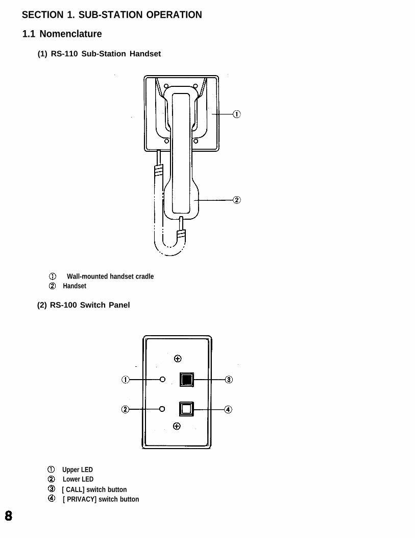
(1) RS-110 Sub-Station Handset
Wall-mounted handset cradle Handset
(2) RS-100 Switch Panel
Upper LED Lower LED [ CALL] switch button [ PRIVACY] switch button
(3) RS-120 Sub-StatIon (Flush-Mount Type)
Speaker [CALL] switch button
(4) RS-130 Sub-Station (Flush-Mount type)
Speaker [CALL] switch button
1.2 Sub-station Speaker Communication
The sub-station speaker is used exclusively for inter-stationsub-station handset. Although either the sub-station handset
communication in rooms not equippedor sub-station speaker can be used in
with arooms
[Note] : (1) If the party being called in Step 3 is on another line or otherwise busy, the LED continuesto flash until the party answers.
(2) Integrated type sub-stations (RS-120 and RS-130) come with neither an LED nor aPrivacy button.
(2) Being Called Following a brief tone, the calling party’s voice is heard. The upper LED lights. Conversation possible. When the conversation ends, the LED goes out.
10
●
(3)
Conversation MethodOnly one party may speak at a time, therefore it is necessary for the other party to finish talkingbefore speaking. The speaker will then function as a microphone to convey your voice. Thismethod of communication is referred to as “half-duplex.”In rooms equipped with sub-station handsets, the handset may be picked up at any time tocontinue the conversation in “full-duplex” mode. For further information, refer to Section 2. 2-(4)Summary of conversation method.
[Note]: An intermittent signal tone can be heard over the speaker if another party is calling orlistening in.
Privacy Switch Use
This switch is used to stop incoming calls or prevent in-room conversations from being overheard.
[Privacy Mode Registration]Press the white [PRIVACY] switch, lighting the lower LED.
[Privacy Mode Cancellation]Press the same switch again, extinguishing the LED.
[Note]: (1) The sub-station can still be called while the privacy mode is enabled, although in-roomconversation cannot be heard. To answer the call, press the [PRIVACY] switch(extinguishing the lower LED) and proceed with the conversation.
(2) Call switch operation remains possible even while the privacy mode is enabled. Theprivacy mode is resumed when the conversation ends.
(4) Emergency Calls [Selectable Function]In emergency situations, continuously press the red [CALL] switch for at least 3 seconds.
For at least 3 seconds
[Note]: No emergency calls can beaccepted during emergencyall-call paging. in such a case,restart operation.
1.3 Sub-Station Handset Use
All sub-stations include the switch panel, whether the sub-station handset is installed or not. Although either thesub-station handset or sub-station speaker can be used in rooms equipped with both, only sub-station handsetuse will be explained in this section. Refer to Section 1.2 for Sub-station speaker applications.
(1) Calling
Lift up the sub-station handset.The corresponding upper LED on the switch panel flashes.The flashing LED remains lit when the party being called answers.Conversation possible.Replace the handset when the conversation ends.The LED goes out.
[Note]:
(2) Being
If the party being called in Step 3 is on another line or otherwise busy, the LED continuesto flash until the party answers. In this case, simply wait for the other party to answer byeither holding the handset or replacing it in its cradle.
Called
Following a brief tone, the calling party’s voice is heard.The upper LED on the switch panel lights.Lift up the sub-station handset.Conversation possible.Replace the handset when the conversation ends.The LED goes out.
12
(4)
Conversation MethodWhile the control station handset remains in its cradle, the conversation method will be half-duplexlike the conversation through the sub-station speaker. When the handset is used, regular 2-waytelephone (full-duplex) conversation becomes possible.
Privacy Mode Conversation (Lower LED lit)
The sub-station can still be called while the privacy mode is enabled, although in-room conversationcannot be heard. To answer the call, press the [PRIVACY] switch (extinguishing the lower LED) andproceed with the conversation.Picking up the sub-station handset makes a call even while the privacy mode is enabled. The privacymode is resumed when the handset is replaced.
Emergency Calls [Selectable Function]In emergency situations while the handset is in use, continuously press the red [CALL] switch for atleast 3 seconds.
[Note]: No emergency calls can beaccepted during emergencyall-call paging. In such a case,restart operation.
13
SECTION 2. Basic Control Station Operation
Nomenclature and Functions
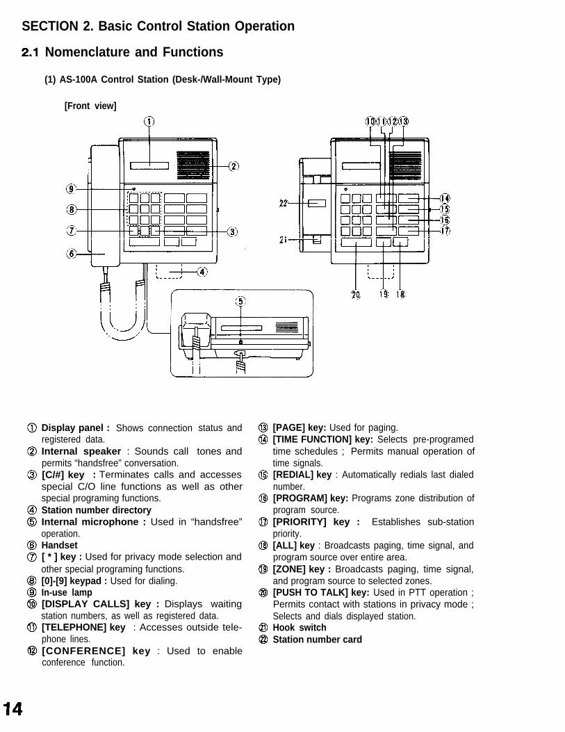
(1) AS-100A Control Station (Desk-/Wall-Mount Type)
[C/#] key : Terminates calls and accessesspecial C/O line functions as well as otherspecial programing functions.Station number directoryInternal microphone : Used in “handsfree”operation.Handset[ * ] key : Used for privacy mode selection andother special programing functions.[0]-[9] keypad : Used for dialing.In-use lamp[DISPLAY CALLS] key : Displays waitingstation numbers, as well as registered data.[TELEPHONE] key : Accesses outside tele-phone lines.[CONFERENCE] key : Used to enableconference function.
[PAGE] key: Used for paging.[TIME FUNCTION] key: Selects pre-programedtime schedules ; Permits manual operation oftime signals.[REDIAL] key : Automatically redials last dialednumber.[PROGRAM] key: Programs zone distribution ofprogram source.[PRIORITY] key : Establishes sub-stationpriority.[ALL] key : Broadcasts paging, time signal, andprogram source over entire area.[ZONE] key : Broadcasts paging, time signal,and program source to selected zones.[PUSH TO TALK] key: Used in PTT operation ;Permits contact with stations in privacy mode ;Selects and dials displayed station.Hook switchStation number card
[Top view]
[Side view]
15
(2) AS-110 Control Station (Console-/Wall-Mount Type)
[Front view] [Front view without a speaker cover]
Handset Display panel : Shows connection status and
station numbers, as well as registered data. [TELEPHONE] key : Accesses outside
telephone lines.
[CONFERENCE] key : Used to enableconference function.
[PAGE] key: Used for paging. [TlME FUNCTION] key: Selects pre-programed
time schedules ; Permits manual operation oftime signals.
[REDIAL] key : Automatically redials last dialednumber.
[PROGRAM] key: Programs zone distribution ofprogram source.
[PRIORITYl key : Establishes sub-stationpriority.
[ALL] key: Broadcasts paging, time signal, andprogram source over entire area.
[ZONE] key : Broadcasts paging, time signal,and program source to selected zones.
Permits contact with stations in privacy mode ;Selects and dials displayed station.
Station number card Hook switch
16
[Note]: (1)
(2)
(3)
(3.1)
(3.2)
(3.3)
(3.4)
Dialing can be performed with either the handset Iifted or in place (handsfree operation).Likewise calls can be answered in either condition if the calls are from internal stations.
System programing procedures are not provided in this manual. Refer to the accompanyingInstallation Manual for this information.
Using an external headset or microphone
Although use of the above-mentioned external headset and microphone are not explainedin this manual, if a headset is connected, its operation is essentially the same as that of thehandset. Likewise, if an external microphone is connected, its operation is essentially thesame as that of the internal microphone.
<For only the systems employing the Duress Alarm function>When an external headset or microphone is connected to the MIC/HEADSET jack, asingle tone is heard. Press the[C/#] key upon hearing the tone. (If the [C/#] key is notpressed, the “duress alarm” function is operated. In such cases, press the [C/#] key, thenremove the headset (microphone) from the jack.)
To disable an internal speaker when using the headset, the control station has to bemodified. (Refer to the IC-100 installation handbook.)
Be sure to connect the headset (microphone) only when the exchange power is ON (i.e.when characters are indicated on the display panel). Note that if the exchange powerswitch is set to ON with the headset (microphone) connected, a one-way conversation by[PUSH TO TALK] key will result instead of a simultaneous (duplex) conversation.
2.2 Internal Line Call Operation
(1) Calling
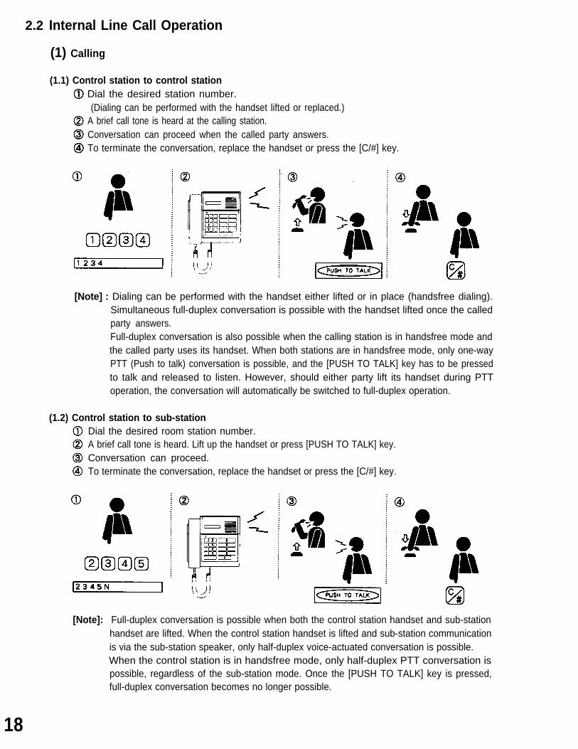
(1.1) Control station to control stationDial the desired station number.(Dialing can be performed with the handset lifted or replaced.)
A brief call tone is heard at the calling station.Conversation can proceed when the called party answers.To terminate the conversation, replace the handset or press the [C/#] key.
[Note] : Dialing can be performed with the handset either lifted or in place (handsfree dialing).Simultaneous full-duplex conversation is possible with the handset lifted once the calledparty answers.Full-duplex conversation is also possible when the calling station is in handsfree mode andthe called party uses its handset. When both stations are in handsfree mode, only one-wayPTT (Push to talk) conversation is possible, and the [PUSH TO TALK] key has to be pressedto talk and released to listen. However, should either party lift its handset during PTToperation, the conversation will automatically be switched to full-duplex operation.
(1.2) Control station to sub-stationDial the desired room station number.A brief call tone is heard. Lift up the handset or press [PUSH TO TALK] key.Conversation can proceed.To terminate the conversation, replace the handset or press the [C/#] key.
[Note]: Full-duplex conversation is possible when both the control station handset and sub-stationhandset are lifted. When the control station handset is lifted and sub-station communicationis via the sub-station speaker, only half-duplex voice-actuated conversation is possible.When the control station is in handsfree mode, only half-duplex PTT conversation ispossible, regardless of the sub-station mode. Once the [PUSH TO TALK] key is pressed,full-duplex conversation becomes no longer possible.
18
(2) Being Called
(2.1)
(2.2)
Control station to control station A brief call tone is heard. Conversation possible upon answering. Conversation ends.
If the conversation has been terminated by the calling party, the called party need not operate anykey for termination. The called party can terminate the conversation by replacing the handset orpressing the [C/#] key.
Sub-station to control station A call tone is heard. Conversation possible upon answering. To terminate the conversation, either replace the handset or press the [C/#] key.
[Note]: (1) The call tone differs depending on the priority level of the station. Refer to the “Section(6) Sub-Station Display Priorites” of this operation manual.
(2) Refer to the “Section 3.2 Internal Line calls (1) Selective Response” and “Section 5.2Priority Order” of IC-100’s Functions and Operating Instructions.
19
(3)
(4)
Privacy Function
This function is used to refuse all incoming calls. The control station can be put in Privacy mode bypressing the [ * ] key twice, showing “PV" and the current time on the station display ([PV A 10:34pm]). If a call is received while in the Privacy mode, a privacy tone is heard. Pressing the [ * ] and [C/#]keys cancels the Privacy mode and extinguishes the “PV" display ([A 10:34pm]). Response to calls can still be made from the control station while the Privacy mode is enabled. If acall is made from” the control station to another control station in the Privacy mode, a Privacy signalsounds at the calling and called stations for a period of time. This signal is different from that heardwhen calling a sub-station in Privacy mode. (Control station privacy tone : Intermittent trill tone,Sub-station privacy tone: Intermittent single tone)
Summary of Conversation Method
(4.1)
(4.2)
(4.3)
In summary, there are three different conversation methods:
Simultaneous conversation (Duplex)Similar to that of a standard telephone.
Voice-actuated two-way conversation (V.S.)The conversation flow is automatically switched via the voice switch. in quiet areas, this is similar tosimultaneous conversation. However, when the ambient noise level at the control station is too high,interfering with smooth conversation, the [PUSH TO TALK] key can be depressed to switch to the PTTconversation mode.
PTT conversation (PTT)The control station [PUSH TO TALK] key is pressed to talk, and released to listen.The following table shows the conversation modes for all of the various station combinations.
[Note]: Conversation between sub-station handsets is possibletransferred to the other handset via the control station.
only when a call from either handset is
20
Sub-Station Mode Displays
(5.1)
(5.2)
“Busy”, “Privacy”, and “Off-Hook” indicators are displayed before their corresponding sub-stationnumbers on the control station display when these modes are in effect. “Busy” and “Privacy” displaysare also accompanied by signal tones.
(5.3)
(6)
Busy modeThe busy tone sounds and the “Busy” indicator is displayed whenever a sub-station is called whilein use.
Privacy modeThe privacy tone sounds and the “Priv.” indicator is displayed whenever a sub-station is called whilein the privacy mode.
Off-hook modeThe “Off-Hook” indicator is displayed whenever a sub-station handset is not replaced within 10seconds after ending a conversation. Replacing the sub-station handset extinguishes this indicator,which is only displayed while the control station is in its waiting mode. However, if any othersub-station handset is also off its hook, this indicator will continue to be displayed in front of thesub-station’s corresponding number.
Sub-Station Display Priorities
The numbers of all stations calling a control station are automatically stored and displayed in thepriority order registered for each station. The control station can only display one of these “waiting”stations. When more than one station is waiting, the other waiting station number can be displayedwith subsequent depressions of the [DISPLAY CALLS] key.
The following three fixed priority indications, shown in descending order of priority, can only beprogrammed within the system during system setup:
The followingstation:
(A) Alarm (N) Normal (S) Staff
programmable priority indication can
(P) Priority
[Note] : This highest “P” priority setting can becorresponding control station.
be independently programmed at each control
temporarily assigned to any sub-station at its
Taking precedence over these priorities is an Emergency Call. Emergency Calls can be made withspecial key operations. Regardless of its arrival order, it is always displayed first whatever the priorityof the other waiting stations. Priority levels of control stations are fixed to be lower than those ofsub-stations.Shown below are the registered priority displays and call tone types produced at the called controlstation. Call tones are not sounded at the called station if busy, in which case a busy tone is heard atthe calling station.
21
[Note]: (1) Waiting stations are arranged in priority order, with those havingdisplayed on a first-come-first-served basis.
(2) The numbers of calling control stations are also stored if the called
the same priority
control station hasbeen called from other stations.
(3) Incoming calls cannot be accepted while busy without terminatingtion.
(*1) A brief trill tone is heard when an unused control station is called.
the current conversa-
[Call Display Examples]No.1234 calling.Other stations calling.Connect to No.1234.No.2345 calling during conversation with No.1234.Other stations besides No.2345 calling during conversation withNo.1234.
[Note]: The suffix “M” indicates other waiting stations, which can be displayed with subsequentdepressions of the [ DISPLAY CALLS ] key.
22.
(7) Emergency Functions [Selectable Function]
(7.1)
(7.2)
(7.3)
Emergency callThis function is applicable only to sub-stations.In emergency situations? continuously press the red [CALL] switch for at least 3 seconds.The emergency call has the highest priority of all station calls.[Note]: Neither emergency calls nor duress alarms can be accepted during emergency all-call
paging. (In such a case, restart operation.)
Duress alarmThis function is applicable only to control stations. In case of an emergency, simply take handset offits hook. The message [OFF-HOOK] will be displayed at the station six seconds after the handsetis displaced, causing all other connected control stations to display the messageaccompanied by an emergency tone (not audible at the busy station).The duress alarm function can be cancelled by replacing the handset after the [C/#] key depression.
[Note] : Voice transmission is not enabled by this function. To establish contact with the station induress, its station No. must be first dialed at any of the receiving stations. However, it maybe difficult to monitor the station in duress owing to the relatively poor sensitivity of thehandset microphone in comparison with the station’s “Handsfree” mode microphone.
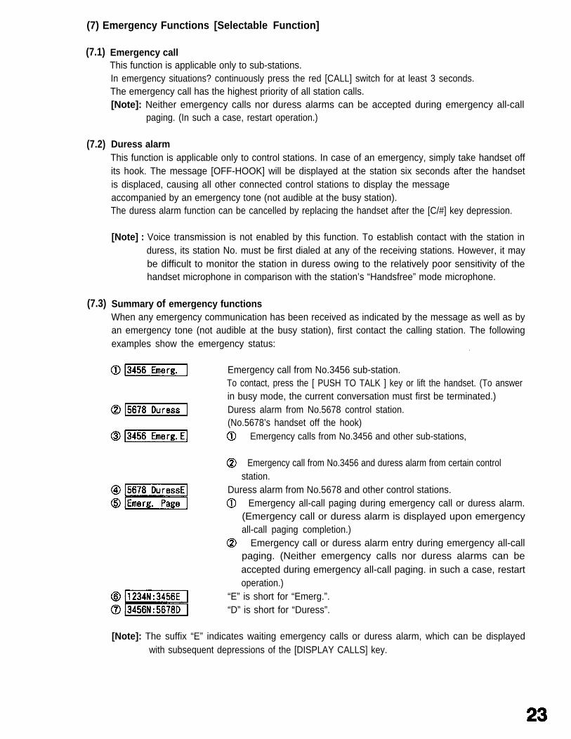
Summary of emergency functionsWhen any emergency communication has been received as indicated by the message as well as byan emergency tone (not audible at the busy station), first contact the calling station. The followingexamples show the emergency status:
‘
Emergency call from No.3456 sub-station.To contact, press the [ PUSH TO TALK ] key or lift the handset. (To answerin busy mode, the current conversation must first be terminated.)Duress alarm from No.5678 control station.(No.5678’s handset off the hook) Emergency calls from No.3456 and other sub-stations,
Emergency call from No.3456 and duress alarm from certain controlstation.
Duress alarm from No.5678 and other control stations. Emergency all-call paging during emergency call or duress alarm.
(Emergency call or duress alarm is displayed upon emergencyall-call paging completion.)
Emergency call or duress alarm entry during emergency all-callpaging. (Neither emergency calls nor duress alarms can beaccepted during emergency all-call paging. in such a case, restartoperation.)
“E” is short for “Emerg.”.“D” is short for “Duress”.
[Note]: The suffix “E” indicates waiting emergency calls or duress alarm, which can be displayedwith subsequent depressions of the [DISPLAY CALLS] key.
2.3 Outside Call Operation [Selectable Function]
(1) Calling
Press [TELEPHONE] key. (*1) Dial [Tel :0797712] Outside telephone call tone is heard. Lift up the handset. (The handset can be lifted before dialing.) Conversation can proceed when called party answers. Replace the handset to terminate the conversation.
[Note] : (*1) For systems connected to both the C/O line and PBX, assign access Nos.1 and 2 todistinguish between the two. Refer to “3.4 PBX Station Intercommunication”.(Ex.: [ TELEPHONE ] [ 1 ] for C/O line calls, [ TELEPHONE ] [ 2 ] for PBX station calls)
(2) Being Called
Outside telephone call tone is heard. [ C/O LINE ]Conversation can proceed by lifting up the handset.Replace the handset to terminate the conversation.
2.4 Paging [Selectable Function]
The following five paging methods are available to all control stations. In addition to these, the IC-100 alsopermits all-call paging from a connected external microphone, and all paging functions can be programmed forexternal PA paging.
Five different paging methods, including All-Call paging, can be selected with the IC-100 system.
Press [PAGE] [ ALL ] keys.Press [ PUSH TO TALK ] key or lift handset. (Paging possible.)
Permits simultaneous paging through all zones. (No paging output isprovided from the stations not assigned to any zone.)Permits simultaneous paging of up to nine pre-programed individualzones (single-digit system) or up to 60 zones (virtually 59 zonesbecause zone No. 60 is used for all-zone time signal broadcast)(double-digit system).Permits simultaneous paging of up to nine pre-programed combina-tions of zones.Permits simultaneous paging of up to ten individual sub-stations.Permits simultaneous emergency paging through all zones andconnected external speakers.
(1) All-Call Paging
A 4-note chime or paging pre-announcement tone sounds.Place a paging call.Replace handset or press [ C/# ] key to terminate the call.
(2)
(3)
Zone Paging
Press [PAGE] [ZONE] keys. Dial the desired zone number(s). (Max. 9 zones can be selected simultaneously.) Press [ PUSH TO TALK ] key or lift handset. (Paging possible.) A 4-note chime or paging pre-announcement tone sounds. Place a paging call. Replace handset or press [ C/# ] key to terminate the call.
●
Combination Zone Paging
Press [ PAGE ] key. Dial the desired combination zone number(s). (Max. 9 combinationzones) Press [ PUSH TO TALK ] key or lift handset. (Paging possible.)
A 4-note chime or paging pre-announcement tone sounds. Place a paging call. Replace handset or press [ C/# ] key to terminate the call.
J
(4)
(5)
Sub-Station Paging
Press [ PAGE ] [ * ] keys. Dial the desired sub-station number(s). (Max. 10 stations) Press [ PUSH TO TALK ] key or lift handset: (Paging possible.) A 4-note chime or paging pre-announcement tone sounds. Place a paging call. Replace handset or press [ C/# ] key to terminate the call.
Emergency All-Call Paging
Press [ PAGE ] key four times or more in rapid sequence.(The emergency page cannot be performed if the intervalexceeds 0.5 seconds.)An emergency all-call paging pre-announcement tone sounds.Place a paging call.Replace handset or press [ C/# ] key to terminate the call.
27
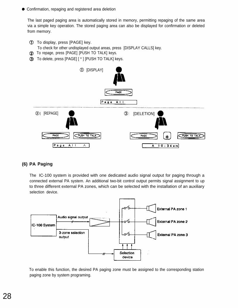
. Confirmation, repaging and registered area deletion
28
The last paged paging area is automatically stored in memory, permitting repaging of the same areavia a simple key operation. The stored paging area can also be displayed for confirmation or deletedfrom memory.
To display, press [PAGE] key. To check for other undisplayed output areas, press [DISPLAY CALLS] key. To repage, press [PAGE] [PUSH TO TALK] keys. To delete, press [PAGE] [ * ] [PUSH TO TALK] keys.
[DISPLAY]
[REPAGE] ●
(6) PA
The
[DELETION]
Paging
IC-100 system is provided with one dedicated audio signal output for paging through aconnected external PA system. An additional two-bit control output permits signal assignment to upto three different external PA zones, which can be selected with the installation of an auxiliaryselection device.
To enable this function, the desired PA paging zone must be assigned to the corresponding stationpaging zone by system programing.
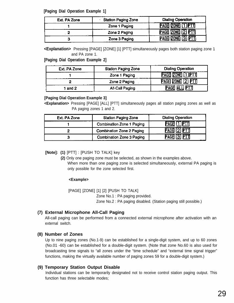
[Paging Dial Operation Example 1]
(7)
(8)
(9)
<Explanation> Pressing [PAGE] [ZONE] [1] [PTT] simultaneously pages both station paging zone 1and PA zone 1.
[Paging Dial Operation Example 2]
[Paging Dial Operation Example 3]<Explanation> Pressing [PAGE] [ALL] [PTT] simultaneously pages all station paging zones as well as
PA paging zones 1 and 2.
[Note]: (1) [PTT] : [PUSH TO TALK] key(2) Only one paging zone must be selected, as shown in the examples above.
When more than one paging zone is selected simultaneously, external PA paging isonly possible for the zone selected first.
<Example>
[PAGE] [ZONE] [1] [2] [PUSH TO TALK]Zone No.1 : PA paging provided.Zone No.2 : PA paging disabled. (Station paging still possible.)
External Microphone All-Call PagingAll-call paging can be performed from a connected external microphone after activation with anexternal switch.
Number of ZonesUp to nine paging zones (No.1-9) can be established for a single-digit system, and up to 60 zones(No.01 -60) can be established for a double-digit system. (Note that zone No.60 is also used forbroadcasting time signals to “all zones under the “time schedule” and “external time signal trigger”functions, making the virtually available number of paging zones 59 for a double-digit system.)
Temporary Station Output DisableIndividual stations can be temporarily designated not to receive control station paging output. Thisfunction has three selectable modes;
29
(9.1) Disable mode
Total output disableTotally omits stations from their assigned broadcast zones, with no access to outputs from anycontrol station in the system.
Limited output disable (Without automatic reset)Omits stations from their registered control station output.Output from other control stations can still be received. (Remains in effect until cancelled by adialing operation.)
Limited output disable (With automatic reset)Omits stations from their registered control station output.Output from other control stations can still be received. (Automatically cancelled with voice orsignal tone transmission.)
[Note] : The Station Output Disable function is not operated (designated stations receive output)when any of the following paging is made:(1) Emergency all-call paging(2) External microphone all-call paging(3) PBX station paging
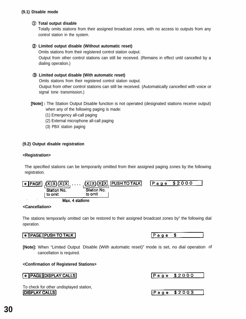
(9.2) Output disable registration
<Registration>
The specified stations can be temporarily omitted from their assigned paging zones by the followingregistration.
<Cancellation>
The stations temporarily omittedoperation.
[Note]: When “Limited Outputcancellation is required.
can be restored to their assigned broadcast zones by” the following dial
Disable (With automatic reset)” mode is set, no dial operation
<Confirmation of Registered Stations>
To check for other undisplayed station,
30
of
(9.3) Output disable indicationWhen omitting stations from their registered station output, the "$" indication is displayed on thecontrol station at the paging dial operation.
(10)
(11)
(12)
Summary of Paging Operation
Transmission Priority List
Emergency all-call paging *1 Emergency call All-call paging/External microphone all-call paging *2 Zone/Combination zone *2 Conversation (including unanswered calls)[Note]: *1: Overridden lower priority functions not restored, even after function completion.
*2: Overridden lower priority functions restored after function completion.
Dial Operation While Being Paged
(12.1)
(12.2)
Emergency all-call pagingDialing cannot be performed from the station that is receiving Emergency all-call paging.
Other pagingDialing can be performed even while the station is being paged, if it ispaging. The original paging is automatically restored after call completion.
not Emergency ail-call
31
SECTION 3. CONVENIENT CONTROL STATION FUNCTIONS
3.1 Applicable to Both Internal and Outside Calls
(1)
(2)
●
32
RedialingPress [REDIAL] key to automatically call the last dialed number.
Redialing, however, cannot be performed with the [DISPLAY CALLS], [PRIORITY], [ * ], or [C/#] key.
Speed Dialing [Selectable Function]Press one or two numerical keys to dial the pre-programed number.
is a number determined at the time of installation.is a user programmable number ( 0 through 9 ).
A maximum of 10 speed dialingonly one in single-digit dialing.
Speed Dialing Registration
numbers can be registered per control station in 2-digit dialing, or
Function registration selectionPre-determined numberUser programmable number (0 through 9 )Dialing (numerical key) or other function (function key) data, Max. 32 digits, excluding
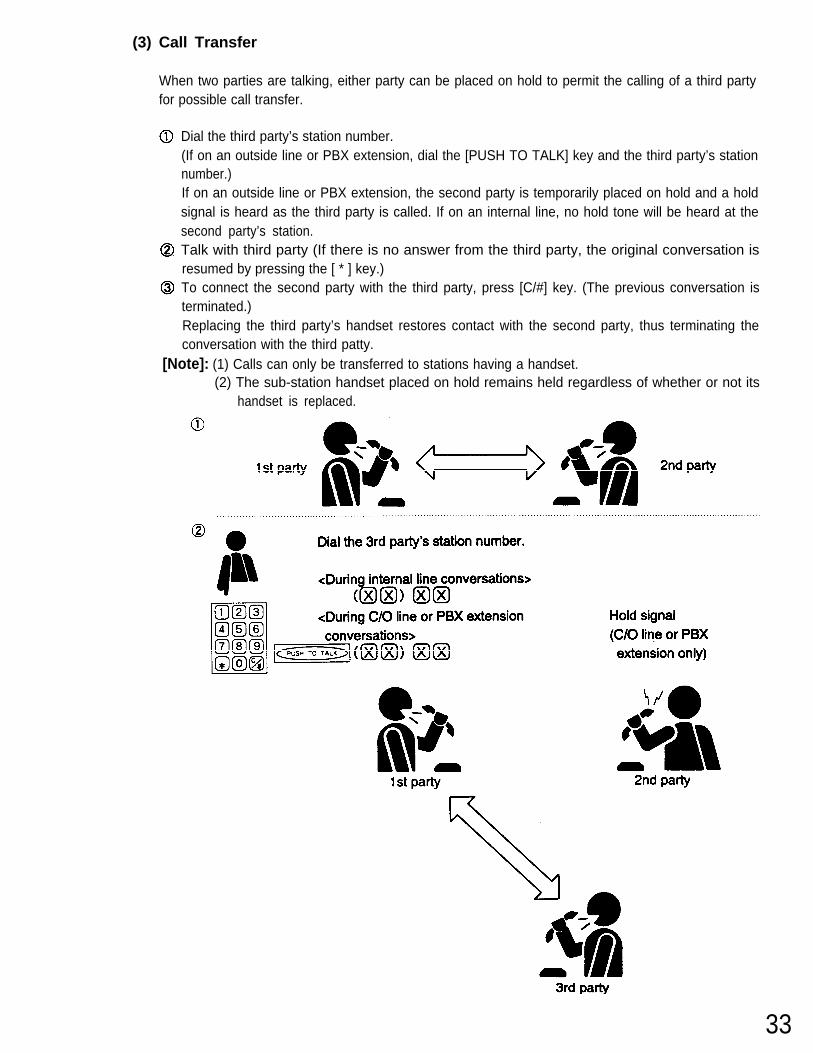
(3) Call Transfer
When two parties are talking, either party can be placed on hold to permit the calling of a third partyfor possible call transfer.
Dial the third party’s station number.(If on an outside line or PBX extension, dial the [PUSH TO TALK] key and the third party’s stationnumber.)If on an outside line or PBX extension, the second party is temporarily placed on hold and a holdsignal is heard as the third party is called. If on an internal line, no hold tone will be heard at thesecond party’s station.Talk with third party (If there is no answer from the third party, the original conversation isresumed by pressing the [ * ] key.)To connect the second party with the third party, press [C/#] key. (The previous conversation isterminated.)Replacing the third party’s handset restores contact with the second party, thus terminating theconversation with the third patty.
[Note]: (1) Calls can only be transferred to stations having a handset.(2) The sub-station handset placed on hold remains held regardless of whether or not its
handset is replaced.
33
To connect the 2nd partywith the 3rd party.
1st party 2nd party
Restores contact with the 2nd party.
(Only possible when the 3rdparty puts down his handset.)
1st party 2nd party
Restores contactwith the 2nd party.
3rd party
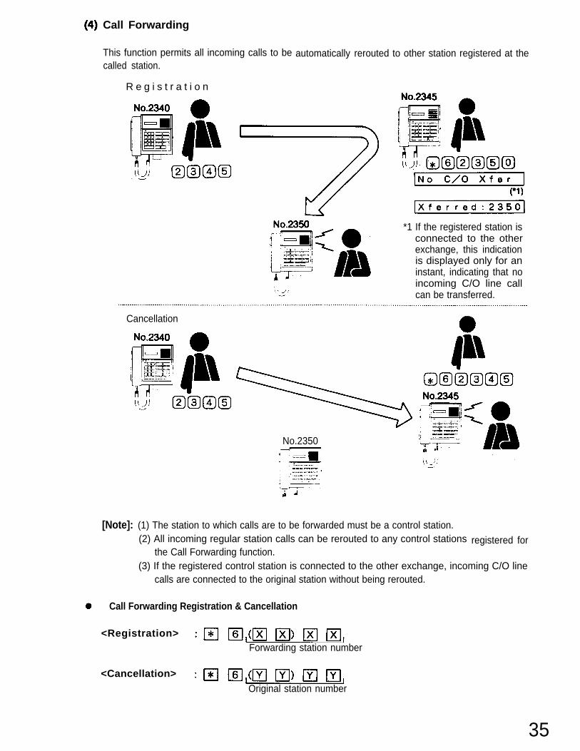
Call Forwarding
This function permits all incoming calls to becalled station.
R e g i s t r a t i o n
automatically rerouted to other station registered at the
*1 If the registered station isconnected to the otherexchange, this indicationis displayed only for aninstant, indicating that noincoming C/O line callcan be transferred.
Cancellation
No.2350
registered for
[Note]: (1) The station to which calls are to be forwarded must be a control station.(2) All incoming regular station calls can be rerouted to any control stations
the Call Forwarding function.(3) If the registered control station is connected to the other exchange, incoming C/O line
calls are connected to the original station without being rerouted.
Call Forwarding Registration & Cancellation
<Registration> Forwarding station number
<Cancellation>Original station number
35
(5) Auto-Call C/O Transfer [Selectable Function]This function permits handset sub-station calls to a control station registered for this function to beautomatically forwarded to a programmed C/O telephone number.
Transfer Registration
Auto-Call C/O TransferN o . 2 3 4 5 _
& 4 4
Sub-station
Transfer Cancellation
Auto-Call C/O Transfer Cancellation
<Auto-Call C/O Transfer Registration>
<Auto-Call C/O Transfer Cancellation>
Control station
(XX) XX: (Original station number)
36
<Handset Sub-Station Operation>
Lift the handset.[CALL] key operation in unnecessary.Replace the handset if the C/O telephone line is busy. The call is retransmitted when the handsetis lifted again.Emergency call operation (which is normally enabled by pressing the call button for more thanthree seconds) is disabled.
[Note]: (1)
(2)
(3)
Auto-call C/O transfer telephone numbers must be pre-programmed for the system.
Auto call C/O transfer applies only to handset sub-station calls. Calls from other controlstations and the incoming C/O line can still be directly made to the control station,regardless of its auto-call transfer setting.
Control stations not directly connected to an exchange set-up with the C/O line interfacehave no access to this function.
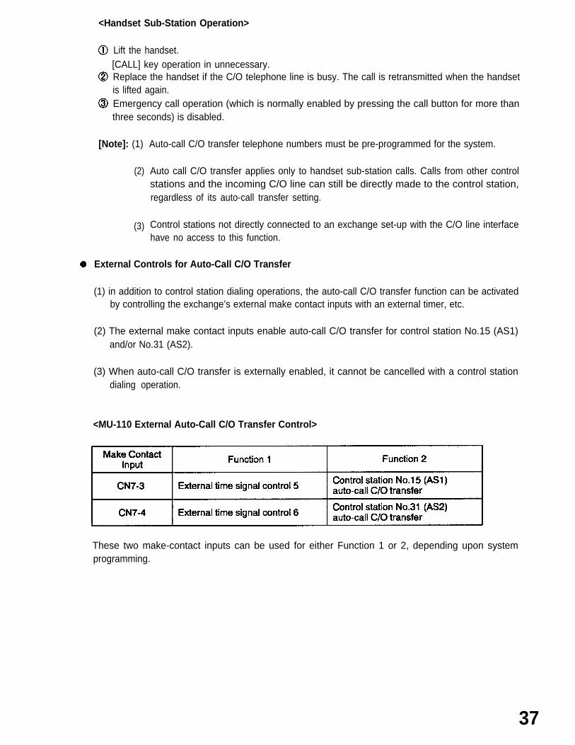
External Controls for Auto-Call C/O Transfer
(1) in addition to control station dialing operations, the auto-call C/O transfer function can be activatedby controlling the exchange’s external make contact inputs with an external timer, etc.
(2) The external make contact inputs enable auto-call C/O transfer for control station No.15 (AS1)and/or No.31 (AS2).
(3) When auto-call C/O transfer is externally enabled, it cannot be cancelled with a control stationdialing operation.
<MU-110 External Auto-Call C/O Transfer Control>
These two make-contact inputs can be used for either Function 1 or 2, depending upon systemprogramming.
37
3.2
No.3456)
38
Internal Line Calls
(1) Selective Response
(1.1) Incoming calls to an unused control station
The station Nos. of all stations simultaneously calling an unused control station are automaticallystored, with the highest priority station No. indicated on its display. When more than one station iswaiting, as indicated by suffix “M”, the other waiting station numbers can be displayed withsubsequent depressions of the [DISPLAY CALLS] key. To answer, advance the display to the desiredstation No. and press the [PUSH TO TALK] key or lift the handset.
[Note] :(1) Waiting stations are arranged in priority order, with those having the same prioritydisplayed on a first-come-first-served basis.
(2) The display returns to its initial status after the last of the waiting stations is displayedwith the [DISPLAY CALLS] key, or when the [C/#] key is depressed.
When a busy control station is called from more than one station, only the currently connectedstation and one waiting station are displayed. The other waiting stations are indicated by a letter “M”and displayed in turn with depression of the [DISPLAY CALLS] key.To answer, first terminate the current conversation, then advance the display to the desired stationNo. before pressing the [PUSH TO TALK] key or lifting the handset. Simply displaying the desiredstation No. during conversation does not permit the connection to that station even afterconversation completion because the display returns to the original status when the conversation isterminated.
[Note ]: Incoming calls from an outside line can also be stored. When there is an outside line callto a busy control station, the message “C/O Line” is displayed. Once the [DISPLAY CALLS]key has been pressed to display other waiting stations during conversation, the messagecan no longer be displayed with the [DISPLAY CALLS] key. It can be displayed only whenthe current conversation is terminated.
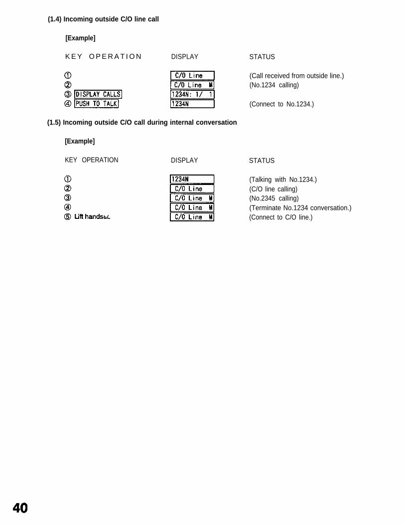
[Example]
KEY OPERATION DISPLAY STATUS
(Talking with No.1234.)(No.2345 calling.)(No.3456 calling.)
(Return to initial display.)(Terminate No.1234 conversation.)
(Connect No.3456.)
[Note ]: (*1) Replacing the handset terminates the original conversation.
(1.5) Incoming outside C/O call during internal conversation
[Example]
KEY OPERATION DISPLAY
STATUS
(Call received from outside line.)(No.1234 calling)
(Connect to No.1234.)
STATUS
(Talking with No.1234.)(C/O line calling)(No.2345 calling)(Terminate No.1234 conversation.)(Connect to C/O line.)
(2) Conference [Selectable Function]
"Conference” conversations can be held with up to three parties if each station is equipped with ahandset.
KEY OPERATION DISPLAY
Press [CONFERENCE] key, then dial the 2ndpatty’s station number.Tell the 2nd party on the conference.Dial the 3rd party’s station number.Three-party conference conversation possible.The conference is terminated if any one ofparticipants (must be the control station) putsdown his handset or presses [C/#] key.
[Note] : (1) Conference calls can also be initiated during regular station-to-station conversation bypressing [CONFERENCE] key and then dialing the third party. (In this event, the caller of theconversation must dial.)If the conference began as a station-to-station conversation, the party first pressing the[CONFERENCE] key becomes the conference initiator.Only the third party can drop out of the original conversation if the conference initiatorpresses the [ * ] key before the third party lifts handset.A call-in during conversation is displayed as [C:1234:3456M].When calling the third party, the first party’s and second party’s handsets must be bothlifted.
(2)
(3)(4)
(3)
●
Control Station Group Call [Selectable Function]
All control stations pre-programmed for the same group can be simultaneously called from asub-station. When one of the control stations within the group answers the call, calls to the othercontrol stations are automatically cancelled.
Control Station Group Call
Control station 1 Control station 2 Control station 3
Control Station Group Response
3.3 Scan Monitor
Any control station can scan an arbitrary group of sub-stations (in consecutive order) for auditory monitoring ofeach sub-station. Scanning can be performed automatically or manually.
(1) Automatic Scanning
(1.1) Scan monitor
Scanning automatically cycles through the sub-station group until manually stopped.
The last monitored stations are automatically stored in memory, permitting remonitor of the samestations via a simple key operation.
[Note] : (1) Control stations cannot be monitored.(2) When a sub-station is busy, no sound is heard from that station when monitored.(3) Unconnected sub-stations must be registered as “no connection” by system
programming.(4) “Scan monitor” function is not operated for five minutes after finishing the system
programing ([REGISTER] switch to OFF.).
Scan Monitor
43
(1.2)
(1.3)
Monitor interval registrationSub-stations can be monitored at a variable interval of 1-9 seconds. (Preset to 1 second.)
(Monitor interval)(1-9 seconds)
Scan monitor cancellationThe scan monitor function can be canceled by either pressing the [C/#] key or replacing the controlstation handset.
(2) Manual Scanning
(2.1)
(2.2)
(2.3)
Automatic scanning stop & restartTo monitor a particular station, press the [PUSH TO TALK] key to stop automatic scanning at thatstation. Pressing the key again will restart the automatic scanning sequence.[PUSH TO TALK]
Scan FORWARDPressing the [ALL] key advances monitoring by one station.
Scan BACKPressing the [ZONE] key reverses monitoring by one station.
<Manual Operation Keys>
44
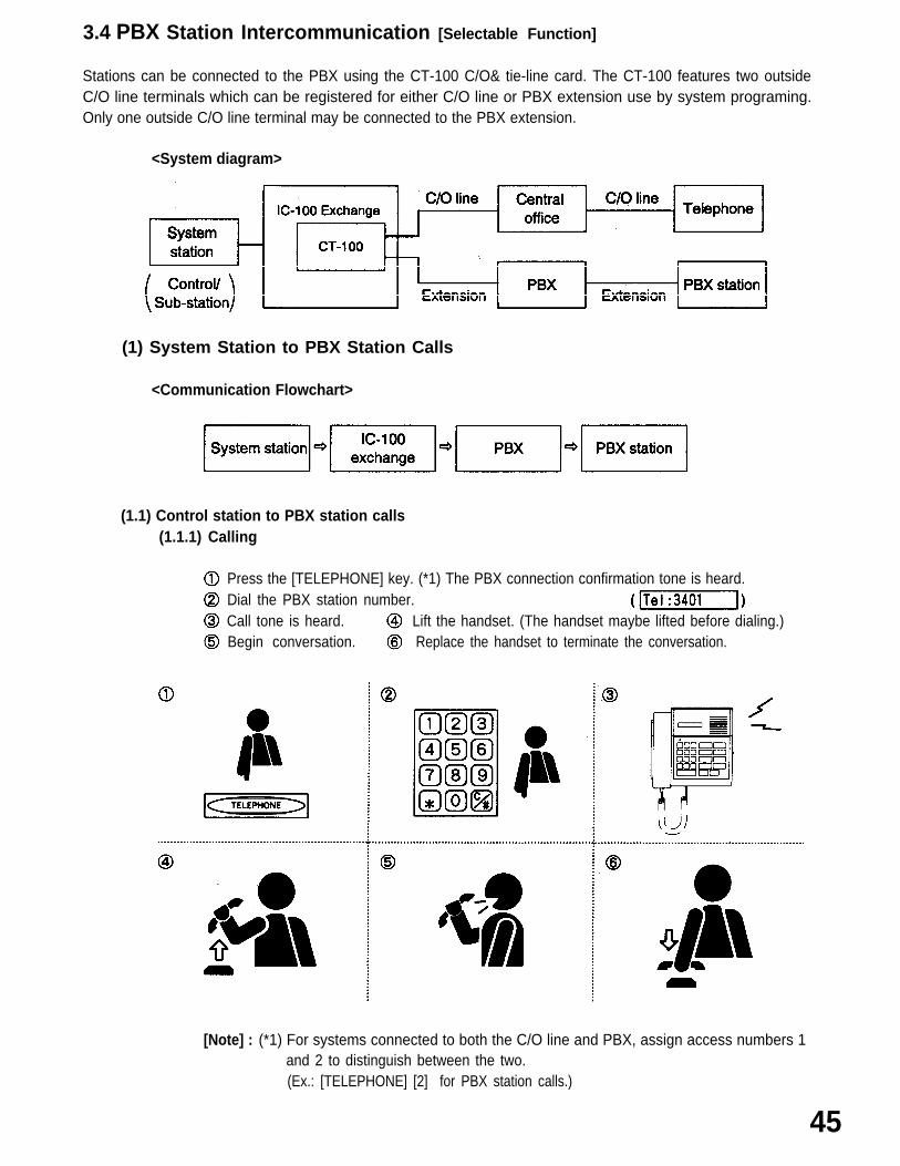
3.4 PBX Station Intercommunication [Selectable Function]
Stations can be connected to the PBX using the CT-100 C/O& tie-line card. The CT-100 features two outsideC/O line terminals which can be registered for either C/O line or PBX extension use by system programing.Only one outside C/O line terminal may be connected to the PBX extension.
<System diagram>
(1) System Station to PBX Station Calls
<Communication Flowchart>
(1.1) Control station to PBX station calls(1.1.1) Calling
Press the [TELEPHONE] key. (*1) The PBX connection confirmation tone is heard.Dial the PBX station number.Call tone is heard.Begin conversation.
Lift the handset. (The handset maybe lifted before dialing.) Replace the handset to terminate the conversation.
[Note] : (*1) For systems connected to both the C/O line and PBX, assign access numbers 1and 2 to distinguish between the two.(Ex.: [TELEPHONE] [2] for PBX station calls.)
45
(1 .2)
46
(1.1.2) Being called The PBX connection confirmation tone is heard. Conversation can proceed by lifting up the handset.
Replace the handset to terminate the conversation.
Sub-station to PBX station calls(The master/sub relationship of the sub-station and desired PBX station must be established inadvance by system programming.)
Lift the handset, and the PBX connection confirmation tone is heard. (The handset may also beleft on the cradle and the [CALL] button pressed, enabling voice-actuated conversation to beinitiated from the PBX station.)Call tone is heard.The called party lifts the PBX station handset.Begin conversation.Replacing the sub-station handset terminates the conversation. Termination from the PBXstation can only be accomplished by first pressing them key and then replacing the handset.
[Caution] : (1) Once the PBX station handset has been replaced without first pressing the [#] key,the conversation can no longer be terminated from the PBX station until the PBXconversation time-out function is operated.
(2) The conversation cannot be terminated from the sub-station unless its handset isused.
I
Sub-station PBX station
Sub-station PBX station
-A Termination from the sub-station -B Termination from the PBX station
Press the [#] key before replacing the handset.
(2)
(2.1)
PBX Station to System Station Calls
<Communication Flowchart>
PBX station to control station calls(2.1.1) Calling
Replace the handset.Dial the designated extension access number (i.e. the PBX extension number assignedto the IC-100 exchange).Dial the control station number.
I (The called party lifts the station handset.)Begin conversation.Press the [#] key and replace the handset to terminate the conversation.
PBX station
Control station
-A Termination from the PBX station – B Termination from the control station
Press the [#] key before replacing the handset.
[Note] : Always be sure to press the [#] key before replacing the PBX station handset,regardless of where the call is initiated.
47
(2.2) PBX station to sub-station calls
Lift the handset.Dial the designated extension access number (i.e. the PBX extension number assigned to theIC-100 exchange).Dial the sub-station number.Begin conversation after a brief calling tone stops. Conversation flow is regulated by avoice-actuated switch that permits only one-way transmission when speaking into the PBXstation. Sub-station voice transmission is only possible when the PBX station is silent.Full-duplex (simultaneous two-way) communication is made possible by lifting the sub-stationhandset.To terminate the conversation at the PBX station, press the [#] key and then replace the handsetregardless of where the call is initiated.
[Caution] : (1) Once the PBX station handset has been replaced without first pressing the [#] key,the conversation can no longer be terminated from the PBX station until the PBXconversation time-out function is operated.
(2) The conversation cannot be terminated from the sub-station unless its handset isused.
PBX station
Extensionaccess No.
PBX station
PBX station
I
Sub-station
Sub-station
Sub-station
-A -BTermination conversation from the PBX station Termination conversation from the sub-station
Press the [#] key before replacing the handset.
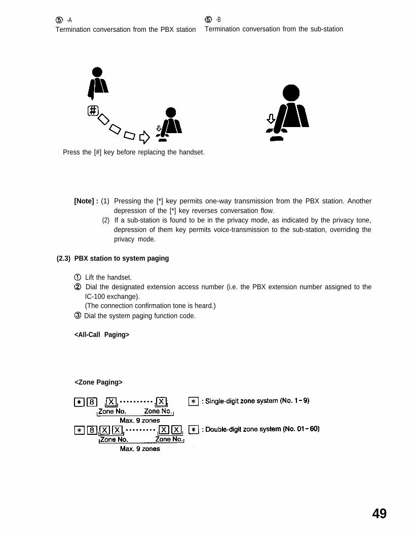
(2.3)
[Note] : (1)
(2)
PBX station
Pressing the [*] key permits one-way transmission from the PBX station. Anotherdepression of the [*] key reverses conversation flow.If a sub-station is found to be in the privacy mode, as indicated by the privacy tone,depression of them key permits voice-transmission to the sub-station, overriding theprivacy mode.
to system paging
Lift the handset. Dial the designated extension access number (i.e. the PBX extension number assigned to theIC-100 exchange).(The connection confirmation tone is heard.)
Dial the system paging function code.
<All-Call Paging>
<Zone Paging>
49
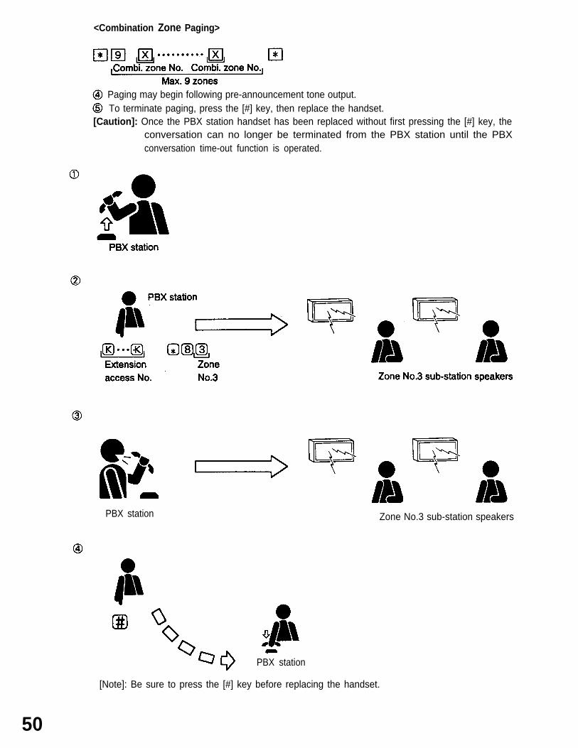
<Combination Zone Paging>
Paging may begin following pre-announcement tone output. To terminate paging, press the [#] key, then replace the handset.
[Caution]: Once the PBX station handset has been replaced without first pressing the [#] key, theconversation can no longer be terminated from the PBX station until the PBXconversation time-out function is operated.
PBX station Zone No.3 sub-station speakers
PBX station
[Note]: Be sure to press the [#] key before replacing the handset.
50
SECTION 4. AUXILIARY FUNCTIONS AND
4.1 Time Setting and Adjustment
OPERATING
(1)
(2)
(3)
Time Setting [Unrestricted Control Station Only]
Current time is set by pressing
PRECAUTIONS
12-/24-hour Mode Switching
Current time can be displayed in either 12-hour or 24-hour mode. Entering [*] [5] [PUSH TO TALK]automatically toggles between the two modes.
Second Synchronization
[Example]
KEY OPERATION DISPLAY
Time display 13:45:27Second display reset to “00”.Display returns to original time displaymode.
Second count 0-30 : Zero reset to same minute.Second count 31-59 : Zero reset to next minute.
[Note]: Zero reset can be performed as often as necessary with subsequent depressions of the[PUSH TO TALK] key.
51
4.2 Station Priority Registration and Calling [Unrestricted control stations only]
As described in “Section 2.2 (6) Sub-station Display Priorities” any one of three priorities (“Alarm”, “Normal”and “Staff) can be assigned to each sub-station. Basically these priorities are determined at the time of systemprograming. However, the higher “Priority” level than “Alarm”, “Normal and “Staff” level can be temporarilyregistered at the control station assigned to the sub-stations its level is registered to.
(1)
(2)
(3)
52
Registration
KEY OPERATION DISPLAY
[Note]: Registration will be completed one second after depression of [PUSH TO TALK ] key, whetheror not [C/#] key is depressed.
Cancellation
KEY OPERATION DISPLAY
Originally designated priority level (“N”) isresumed.
Reviewing the Registered Stations and Call to Them
KEY OPERATION DISPLAY
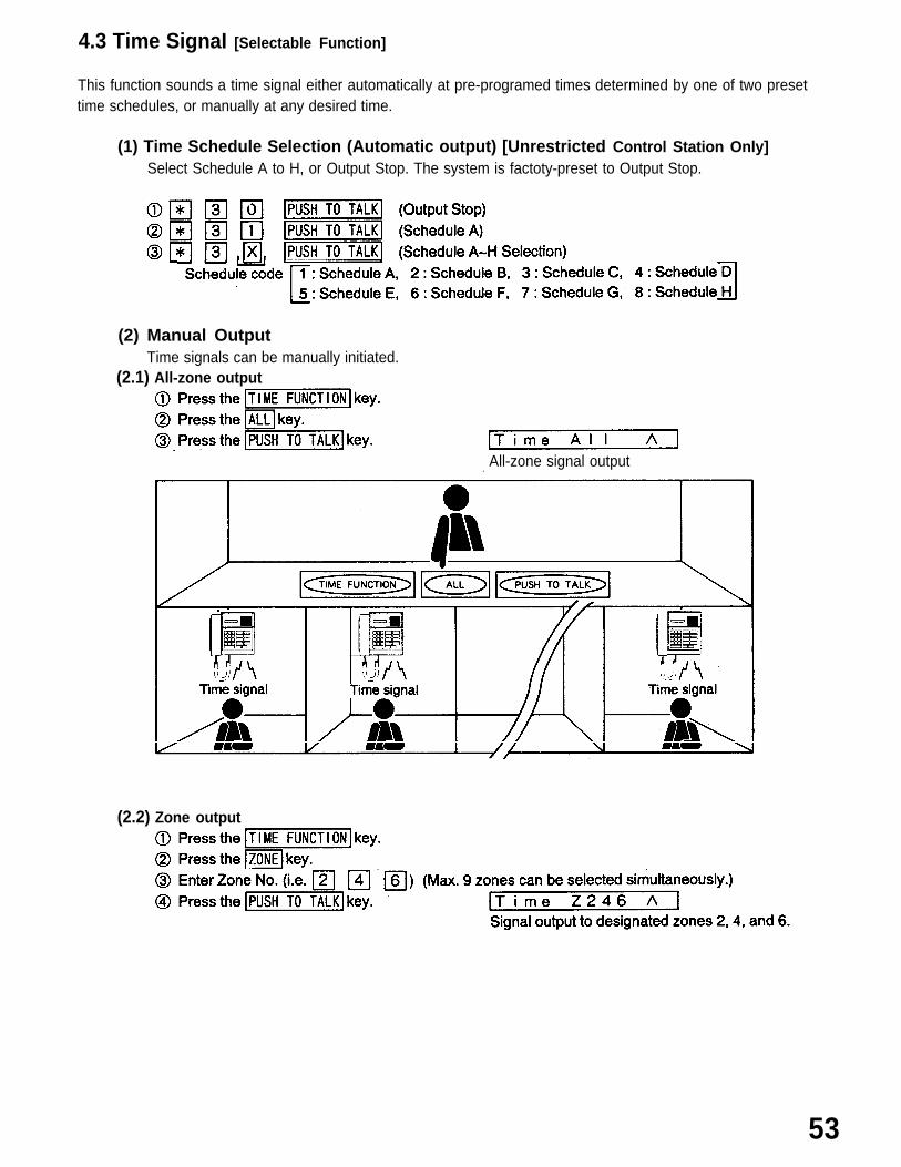
4.3 Time SignaI [Selectable Function]
This function sounds a time signal either automatically at pre-programed times determined by one of two presettime schedules, or manually at any desired time.
(1) Time Schedule Selection (Automatic output) [Unrestricted Control Station Only]Select Schedule A to H, or Output Stop. The system is factoty-preset to Output Stop.
(2) Manual OutputTime signals can be manually initiated.
(2.1) All-zone output
All-zone signal output.
(2.2) Zone output
53
(2.3)
(2.4)
(2.5)
(2.6)
(2.7)
Combination zone output
Sub-station output
Signal output to designated Sub-stations No.2001 and No. 2002.
Confirmation and re-output of registered programs
Number of zonesUp to nine broadcast zones (No.1-9) can be established for a single-digit system, and up to 60zones (No.01 -60) can be established for a double-digit system. (Note that zone No.60 is also usedfor broadcasting time signals to all zones under the “time schedule” and “external time signaltrigger” functions, making the virtually available number of broadcast zones 59 for a double-digitsystem.)
.
Temporary station output disableIndividual stations can be temporarily designated not to receive control station time signal output.This function has three selectable modes;
(2.7.1) Disable modeTotal output disableTotally omits stations from their assigned broadcast zones, with no access to outputs from anycontrol station in the system.Limited output disable (Without automatic reset)Omits stations from their registered control station output.Output from other control stations can still be received. (Remains in effect until cancelled by adialing operation.)Limited output disable (With automatic reset)Omits stations from their registered control station output.Output from other control stations can still be received. (Automatically cancelled with voice orsignal tone transmission.)
[Note] : The Station Output Disable function is not operated (designated stations receive output)when any of the following time signal output is made:
54
(1) Time signal (Automatic Output)(2) External time signal trigger
(2.7.2) Output disable registration
<Registration>
The specified stations can be temporarily omitted from their assigned time signal zones by the followingregistration.
<Cancellation>
The control stations temporarily omitted can be restored to their assigned broadcast zones by thefollowing dial operation.
[Note]: When “Limited Output Disable (With automatic reset)” mode is set, no dial operation ofcancellation is required.
<Confirmation of Registered Stations>
To check for other undisplayed stations,
(2.7.3) Output disable indicationWhen omitting stations from their registered control station output, the “$” indication is displayed on thecontrol station at the time signal dial operation.
<Example>
55
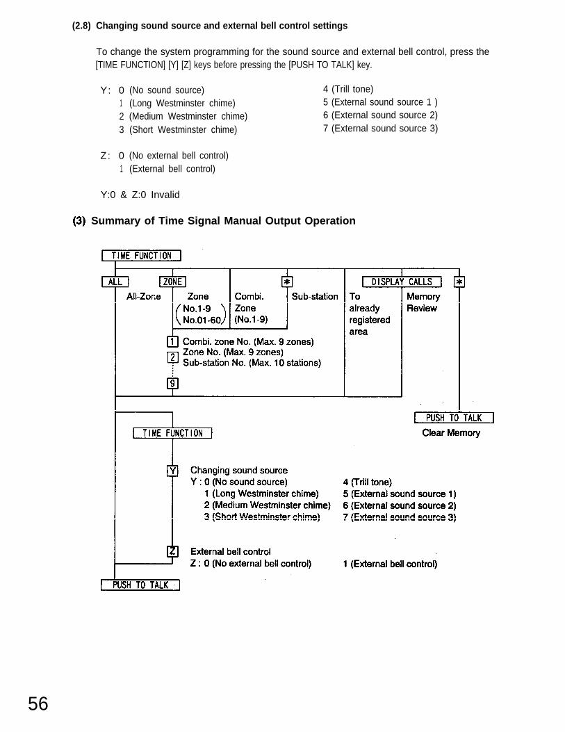
(2.8) Changing sound source and external bell control settings
To change the system programming for the sound source and external bell control, press the[TIME FUNCTION] [Y] [Z] keys before pressing the [PUSH TO TALK] key.
The IC-100 system can output program source material (such as back-ground music) to selected area.
57
(2) Zone Output (2.1) To initiate program source output,
(4) Sub-Station Output(4.1 ) To initiate program source output,
(5) Confirmation; Re-Output and Output Stop of Registered Programs
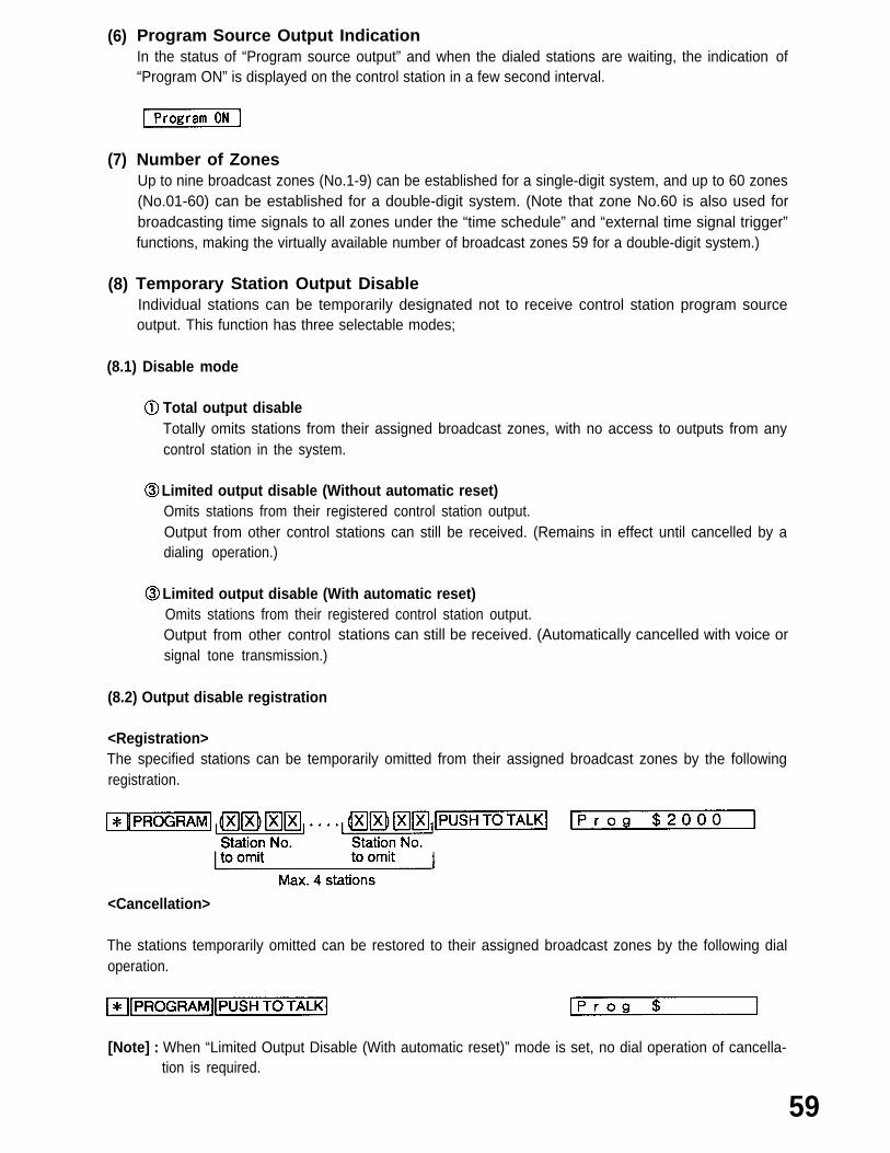
(6) Program Source Output IndicationIn the status of “Program source output” and when the dialed stations are waiting, the indication of“Program ON” is displayed on the control station in a few second interval.
(7)
(8)
Number of ZonesUp to nine broadcast zones (No.1-9) can be established for a single-digit system, and up to 60 zones(No.01-60) can be established for a double-digit system. (Note that zone No.60 is also used forbroadcasting time signals to all zones under the “time schedule” and “external time signal trigger”functions, making the virtually available number of broadcast zones 59 for a double-digit system.)
Temporary Station Output DisableIndividual stations can be temporarily designated not to receive control station program sourceoutput. This function has three selectable modes;
(8.1) Disable mode
Total output disableTotally omits stations from their assigned broadcast zones, with no access to outputs from anycontrol station in the system.
Limited output disable (Without automatic reset)Omits stations from their registered control station output.Output from other control stations can still be received. (Remains in effect until cancelled by adialing operation.)
Limited output disable (With automatic reset)Omits stations from their registered control station output.Output from other controlsignal tone transmission.)
(8.2) Output disable registration
<Registration>
stations can still be received. (Automatically cancelled with voice or
The specified stations can be temporarily omitted from their assigned broadcast zones by the followingregistration.
<Cancellation>
The stations temporarily omitted can be restored to their assigned broadcast zones by the following dialoperation.
[Note] : When “Limited Output Disable (With automatic reset)” mode is set, no dial operation of cancella-tion is required.
59
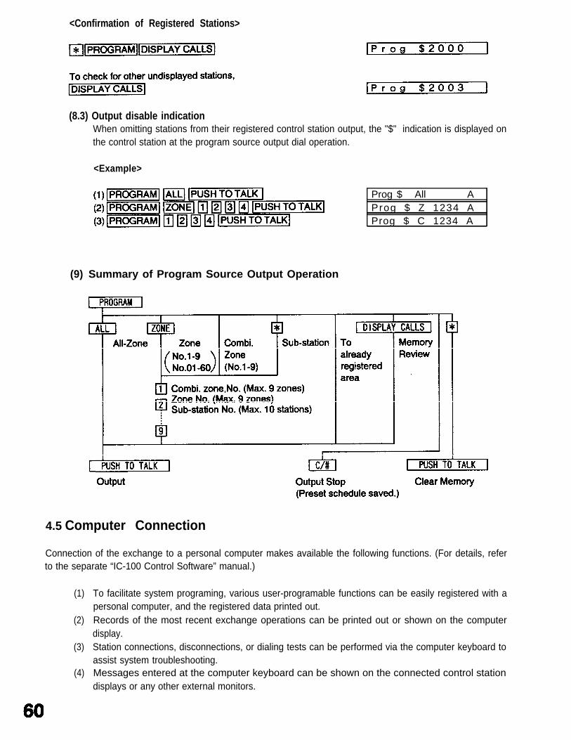
<Confirmation of Registered Stations>
(8.3) Output disable indication
(9)
When omitting stations from their registered control station output, the "$" indication is displayed onthe control station at the program source output dial operation.
<Example>
Prog $ All AProg $ Z 1234 AProg $ C 1234 A
Summary of Program Source Output Operation
4.5 Computer Connection
Connection of the exchange to a personal computer makes available the following functions. (For details, referto the separate “IC-100 Control Software” manual.)
(1)
(2)
(3)
(4)
To facilitate system programing, various user-programable functions can be easily registered with apersonal computer, and the registered data printed out.Records of the most recent exchange operations can be printed out or shown on the computerdisplay.Station connections, disconnections, or dialing tests can be performed via the computer keyboard toassist system troubleshooting.Messages entered at the computer keyboard can be shown on the connected control stationdisplays or any other external monitors.
SECTION 5. FUNCTION AND OPERATION TABLES
5.1 Dialing Operations
(1) Quick Reference to Dialing Operations
(1.1) Sub-Station
Function
Call Transmission
Privacy
Operation Remarks
Call
PBX Station Call*3
I Registered PBX stations only,
Emergency Call*3
Privacy Privacy mode ONPrivacy mode OFF
(1.2) Control Station
Function Operation Remarks
Calling/Response Call xx :00-99xxx :000-999xxxx :0000-9999
Response to
Call
SelectiveResponse
Conversation SimplexFormat
Voice-Actuated Sub-station speaker transmission only (1) With control station
Two-Way possible when control station is silent. (2) With sub-station handset
Conversation
Duplex Lift handset. (1) Control- to sub-station
(Both stations OFF-HOOK) (2) Sub-station to sub-station
Lift handset. Control- to control station
(Either of calling or called Station OFF-HOOK)
Privacy Registration
Cancellation Operation time Interval : Max. 1 sec.
Response Push any key or lift handset.
Conference Calling Only available to handset stations.
Last Station From station that originated
Dropout conference.
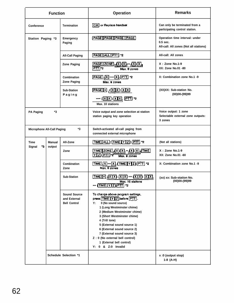
Function Operation Remarks
Conference Termination Can only be terminated from aparticipating control station.
Station Paging *3 Emergency Operation time interval: under
Paging 0.5 sec.All-call: All zones (Not all stations)
All-Call Paging All-call: All zones
Zone Paging X : Zone No.1-9XX: Zone No.01 -80
Combination X: Combination zone No.1 -9
Zone Paging
Sub-Station (XX)XX: Sub-station No.
P a g i n g (00)00-(99)99
Max. 10 stations
PA Paging *3 Voice output and zone selection at station Voice output: 1 zone
station paging key operation Selectable external zone outputs:3 zones
DialOperation*3 Voice-Actuated Two-Way Sub-station speaker transmission only (1) With control station
Conversation possible when PBX station is silent. (2) With sub-station handset
Full-Duplex Conversation (1) With control station(2) With sub-station handset
All-Call PagingExtensionaccess No.
Zone Paging X,1-9,XX:01-60
Extension Max. 9 zonesaccess No.
Combination Zone Paging X: 1-9 (Combination zone)
Extension Max. 9 zonesaccess No.
Termination
PBX Control Station Call XX...X: PBX station No.
Station Access Nos.1 and 2 distinguish
Access *3 C/O line from PBX.
63
64
Function Operation Remarks
PBX PBX Station Call Transfer (XX)XX: Station No. to be
Station transferred toAccess *3 Only possible to handset station.
Call Re-ConnectionNot transferable to C/O fine andPBX station.
C/O Line Calling x . . . . )(: Telephone No.
Access No.1 and 2 distinguishC/O line from PBX.
Receiving Lift handset.
Call Transfer (XX)XX: Station No. to betransferred to
Only possible to handset station.Call Re-Connection
Not transferable to C/O line andPBX station.
Internal Call Transfer (XX)XX : Station No. to beLine transferred to
Only possible to handset station.Call Re-Connection
Not transferable to C/O line andPBX station.
Call Call Forwarding Registration (XX)XX : Control station No. to beForwarding transferred to , .
Auto-Call C/O Transfer Control station calls receivedRegistration without call forwarding.
Cancellation (XX)XX : Originally assignedstation No.
Speed Single-Digit Dialing X : Designated No.Dialing *3 Y: User programabfe
2-Digit Dialing No. (O-9)Z: No. to be registered
Registration (Max. 32 digits)
Redialing
Duress Operation Take handset off for over 6 seconds.Alarm *3
Cancellation
Time Time Setting HH :00-23 (Hour)Setting MM :00-59 (Minute)andAdjustment 12-/24-Hour Mode Switching Toggles between 12-hour
and 24-hour modes.
Function Operation Remarks
Time Second Synchronization 1-30 sec : Zero reset to same
Setting minute.
and 31-59 sec: Zero reset to next
Adjustment m i n u t e .*1
Priority Registration X: Sub-station No.Only possible at control station
assigned to “Priority” sub-station.
Confirmation/Call Toggles between “priority” andoriginally designated priority.
Call Display Memory Clear
Scan Monitoring StartMonitor
Stop/Restart
Single Station FORWARD
Single Station BACK
Scan Intewal Registration X:1-9 (sec.)(Preset for 1 sec.)
[Note] : (1) *1 : Onlv Possible with the “Unrestricted” control or PBX station.*2 : [PUSH TO TALK] or Lift handset.
(2) Some keys and words are abbreviated in this reference list.
(3) *3: Selectable function refers to the functions that can be selected by system programing.
(4) For details of dial-free functions (conversation time-out, calling time-out, Alert tones duringconversation, etc.), refer to the IC-100 Installation Manual, Chapter 5-1., “ProgrammableFunctions”.
65
Transmission Area Registration
[PAGING] [TlME SIGNAL MANUAL OUTPUT] [PROGRAM SOURCE OUTPUT]
[Note] : (1) Only available for “Program Source Output” function.(2) Only available for “Time Signal” function.
66
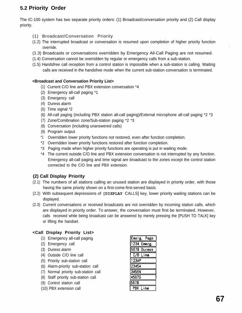
5.2 Priority Order
The IC-100 system has two separate priority orders: (1) Broadcast/conversation priority and (2) Call displaypriority.
(1) Broadcast/Conversation Priority(1.2) The interrupted broadcast or conversation is resumed upon completion of higher priority function
override. .
(1.3) Broadcasts or conversations overridden by Emergency All-Call Paging are not resumed. (1.4) Conversation cannot be overridden by regular or emergency calls from a sub-station.(1.5) Handsfree call reception from a control station is impossible when a sub-station is calling. Waiting
calls are received in the handsfree mode when the current sub-station conversation is terminated.
<Broadcast and Conversation Priority List>(1)(2)(3)(4)(5)(6)(7)(8)(9)*1*2*3*4
Current C/O line and PBX extension conversation *4Emergency all-call paging *1Emergency callDuress alarmTime signal *2All-call paging (including PBX station all-call paging)/External microphone all-call paging *2 *3Zone/Comibnation zone/Sub-station paging *2 *3Conversation (including unanswered calls)Program outputOverridden lower priority functions not restored, even after function completion.Overridden lower priority functions restored after function completion.Paging made when higher priority functions are operating is put in waiting mode.The current outside C/O line and PBX extension conversation is not interrupted by any function.Emergency all-call paging and time signal are broadcast to the zones except the control stationconnected to the C/O line and PBX extension.
(2) Call Display Priority(2.1)
(2.2)
(2.3)
The numbers of all stations calling an unused station are displayed in priority order, with thosehaving the same priority shown on a first-come-first-served basis.With subsequent depressions of [DISPLAY CALLS] key, lower priority waiting stations can bedisplayed.Current conversations or received broadcasts are not overridden by incoming station calls, whichare displayed in priority order. To answer, the conversation must first be terminated. However,calls received while being broadcast can be answered by merely pressing the [PUSH TO TALK] keyor lifting the handset.
No.1234 calling.Other stations calling.Connect toNo.1234.No.2345 calling during conversation with No.1 234.Other stations besides No.2345 calling during conversation with No.1234.(l) Emergency call from No.3456. .(2) Connect to No.3456.(3) Emergency call from No.3456 during conversation with No.1234.(1) Emergency calls from No.3456 and other sub-stations.(2) Another emergency call made during conversation with No.3456.(3) Emergency call from No.3456 and duress alarm from other control
station.Emergency call from No.4567 during conversation with No.3456. (*1 )Duress alarm from No.5678 during conversation with No.3456.(*1 )Emergency call from No.4567 and other station during conversation withNo.3456. (*1)(1) Call from C/O line.(2) Conversation with C/O line.(3) Call from C/O line during conversation with internal line.(1) Calls from both C/O and internal lines.(2) Call from internal line during conversation with C/O line. (1) Call from PBX extension.(2) Conversation with PBX extension.(3) Call from PBX extension during conversation with internal line.(1) Calls from both PBX extension and internal lines.(2) Call from internal line during conversation with PBX extension.Duress alarm from No.5678 control station.Duress alarm from No.5678 and other control station.(1) Emergency all-call paging during emergency call or duress alarm.
(Emergency call or duress alarm is displayed upon emergency all-callpaging completion.)
(2) Emergency call or duress alarm entry during emergency all-call paging.(Neither emergency calls nor duress alarms can be accepted duringemergency all-call paging. In such a case, restart operation.)
(*1) Initial display after confirming undisplayed waiting stations with the [DISPLAY CALLS] key.
[Note] : (1)
(2)
The suffix “M” indicates other waiting stations, which can be displayed with subsequentdepressions of the [DISPLAY CALLS] key.
The suffix “E” indicates waiting emergency calls or duress alarm, which can bedisplayed with subsequent depressions of the [DISPLAY CALLS] key.
69
(2) Transmission
(3) Miscellaneous
Emergency all-call pagingAll-call pagingZone pagingCombination zone pagingSub-station pagingManually activated time signalProgram outputSub-station paging with output disable indicationManually activated time signal with output disable indicationProgram output with output disable indicationOutside C/O line callingPBX station callingInternal callingConference callingCall forwarding from No.1234 to No.2345Duress alarm
“Priority” station registrationCall forwarding registrationAuto-call C/O transferProgram source output indication
70
5.5
5.6
Note on Operation
(1) Emergency Call(1.1) When three or more sub-stations are simultaneously operated while paging is being established in
the system, the regular sub-station calls can be converted into emergency calls.(1.2) Answering an incoming emergency call to a control station by pressing its [PUSH TO TALK] key or
lifting its handset while paging is being established in the system can terminate currentconversations and paging, including those at other stations.
(2)
(3)
(4)
PagingNo paging call can be made from any control station when three or more sub-station calls aresimultaneously operated.
Number of Storable Waiting StationsA maximum of 120 waiting station numbers can be stored and displayed per control station. Incomingcalls received in excess of this capacity are all ignored, including an Emergency call.
Call Display Memory ClearPressing [DISPLAY CALLS] [ALL] [ALL] [ALL] [ALL] keys will delete and disconnect all stored waiting
stations.[Note] : This function cannot be operated while the control station is receiving an Emergency call.
Restrictions by Tie-Line Systems
Note the following restrictions a tie-line system can cause to the C/O line functions when installing the controlstations.
(1) Call Forwarding(1.1) All incoming regular station calls can be rerouted to any
Forwarding function.(1.2) If the registered control station is connected to the other
(2)
(3)
connected to the original station without being rerouted.
Access to C/O Line Calls
control stations registered for the Call
exchange, incoming C/O line calls are
Only the station whose exchange is connected to the C/O line can make or receive a C/O line call.
C/O Line ConversationC/O line conversations are not overriden by the Emergency all-call paging. However, they can beinterrupted (very seldom, though) so as to allow the Emergency all-call paging to go through when agreat number of calls are being “simultaneously made in an entire tie-line system. (The interruptionoccurs only when the total number of C/O lines of the tie-line system is equal to or greater than thatof tie-line links.)