29
Mu2e Project Overview Steve Werkema – Mu2e Accelerator Systems L2 Manager Mu2e Resonant Extraction Design Review 25 August 2015
Mu2e Project Overview
Steve Werkema – Mu2e Accelerator Systems L2 Manager Mu2e Resonant Extraction Design Review 25 August 2015

Outline
• The Mu2e Experiment
• The Muon Campus
• The Mu2e Project Accelerator Systems
• Construction Progress
• Schedule Overview
8/25/2015 S. Werkema | Mu2e Project Overview 2

Mu2e Project Office People You May See at this Review
8/25/2015 S. Werkema | Mu2e Project Overview 3
Ron Ray Mu2e Project Manager
Julie Whitmore Mu2e Deputy Project Manager
Mike Andrews Mu2e ES&H Manager
Kurt Krempetz Mu2e Project Mech. Engineer
George Ginther Mu2e Mechanical Integration Team Coordinator
Dee Hahn Mu2e ES&H Coordinator
Karen Byrum Electrical Integration Team Leader
Gary Drake Project Elec. Engineer

Various Accelerator/Resonant Extraction People
8/25/2015 S. Werkema | Mu2e Project Overview 4
Steve Werkema Mu2e Accelerator Level 2 Manager
Vladimir Nagaslaev Mu2e Accelerator Deputy Level 2 Manager Resonant Extraction L3
Dave Tinsley Mechanical Engineer (ESS)
Matt Alvarez Mechanical Engineer (ESS)
Peter Prieto Electronics Engineer (Spill Regulation)
Leo Michelotti Resonant Extraction Theory
Jerry Annala AD / Muon Department Head
Denton Morris AD / MI Department NWA Test Facility

The Mu2e Experiment
8/25/2015 S. Werkema | Mu2e Project Overview 5

Charged Lepton Flavor Violation
• The Mu2e experiment will attempt to detect Charged Lepton Flavor Violation (CLFV)
• CLFV is a process involving charged leptons (e, µ, τ) that violates the conservation of the number of leptons of each flavor
8/25/2015 S. Werkema | Mu2e Project Overview 6
µ -
e- Al
µ - N → e- N Lµ: 1 0
Le: 0 1
Both Lµ and Le are not conserved in this process ee µµ νν− −→
Lµ: 1 0 0 1
Le: 0 1 -1 0
Ordinary muon decay is not CLFV
If this is observed, it is evidence physics beyond the Standard Model

What Mu2e Measures
The Mu2e experiment will measure the ratio of the number muon captures in aluminum that produce a conversion electron to the number of those that are captured in the ordinary way. This ratio is designated “Rµe”
8/25/2015 S. Werkema | Mu2e Project Overview 7
, ,
, , 1e
A Z e A ZR
A Z A Zµ
µ
µ
µ ν
− −
−
Γ + → +=
Γ + → + −
The goal of Mu2e is to measure Rµe with a single event sensitivity of 2.87×10⁻¹⁷
Rate of CLFV µ → e conversion
µ capture rate

Results of Previous CLFV Searches
8/25/2015 S. Werkema | Mu2e Project Overview 8
COMET Phase I

Mu2e Apparatus
8/25/2015 S. Werkema | Mu2e Project Overview 9
The Mu2e apparatus consists of three superconducting solenoids joined together to make a continuous whole
Production Solenoid • Contains proton target • Magnetic mirror – reflects
secondaries back toward transport solenoid
4.5 T
2.5 T
Transport Solenoid • Collimation • Momentum and charge
selection • Transport to stopping
target
2 T
Detector Solenoid • Contains stopping target • Tracker (straws) • Calorimeter (BaF2 crystals)
1 T
1 T
105 MeV e −
Al Stopping Target • ~ 0.0019 stopped µ−/POT • 1010 Hz of stopped muons
Stopping Muons
8/25/2015 S. Werkema | Mu2e Project Overview 10
µ -
Aluminum Nucleus
Captured µ −
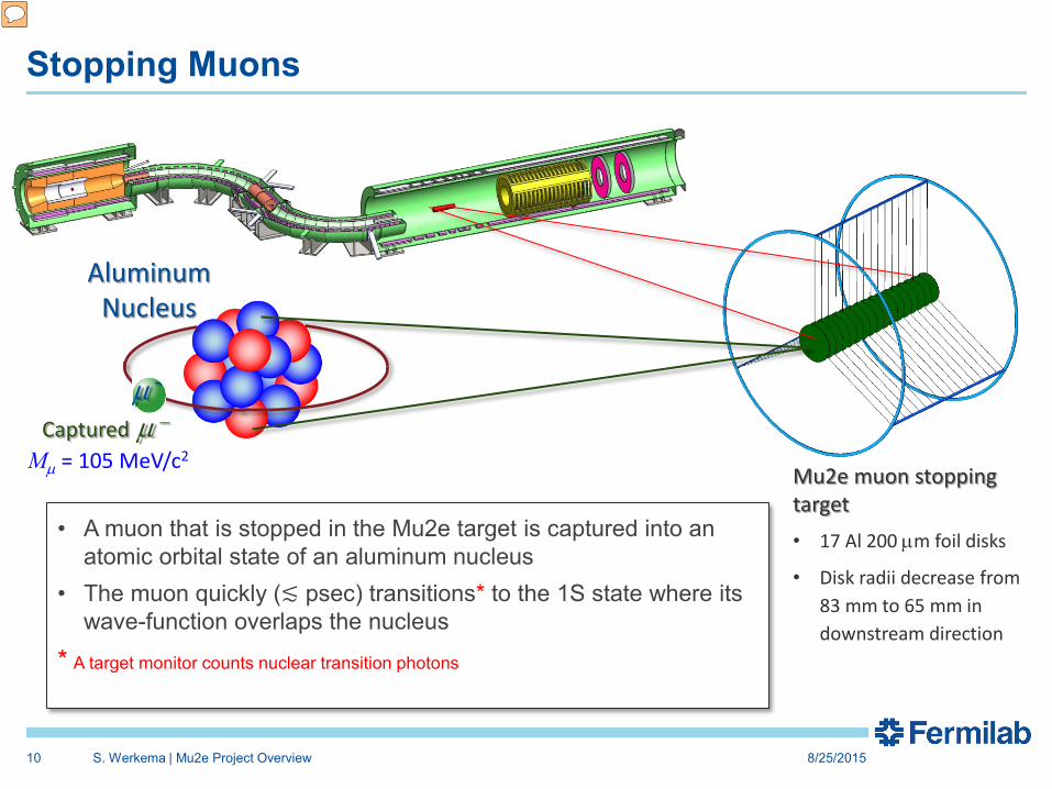
Mµ = 105 MeV/c2 Mu2e muon stopping target • 17 Al 200 µm foil disks
• Disk radii decrease from 83 mm to 65 mm in downstream direction
• A muon that is stopped in the Mu2e target is captured into an atomic orbital state of an aluminum nucleus
• The muon quickly (≲ psec) transitions* to the 1S state where its wave-function overlaps the nucleus
* A target monitor counts nuclear transition photons

The Muon Campus
8/25/2015 S. Werkema | Mu2e Project Overview 11

Acquisition of Beam for Mu2e
8/25/2015 S. Werkema | Mu2e Project Overview 12
Muon Campus
Recycler Ring
Accelerator timeline for Mu2e proton beam delivery • Spill duration: 43.1 msec • Interval between spills 48.1 msec • Duty Factor: 27.1% (Total Spill Time/Length of Cycle) • Peak Delivery Ring proton intensity: 1.0 ×10¹²

The Muon Campus
8/25/2015 S. Werkema | Mu2e Project Overview 13
Picked over remnants of the Antiproton Source
+ a new Recycler RF system
+ Recycler to P1 transfer
+ Beamline upgrades
+ Cryo support
The Muon Campus Program consists of a total of 9 projects

DOE Projects, AIPs, GPPs
Building the Muon Campus requires the following projects:
1. DOE Projects • Muon g-2 • Mu2e
2. AIPs (Accelerator Improvement Projects) • Recycler RF • Beam Transport • MC Cryo Plant • Delivery Ring
3. GPPs (General Plant Projects) • MC-1 Building • Beamline Enclosure • MC Infrastructure Upgrade
8/25/2015 S. Werkema | Mu2e Project Overview 14
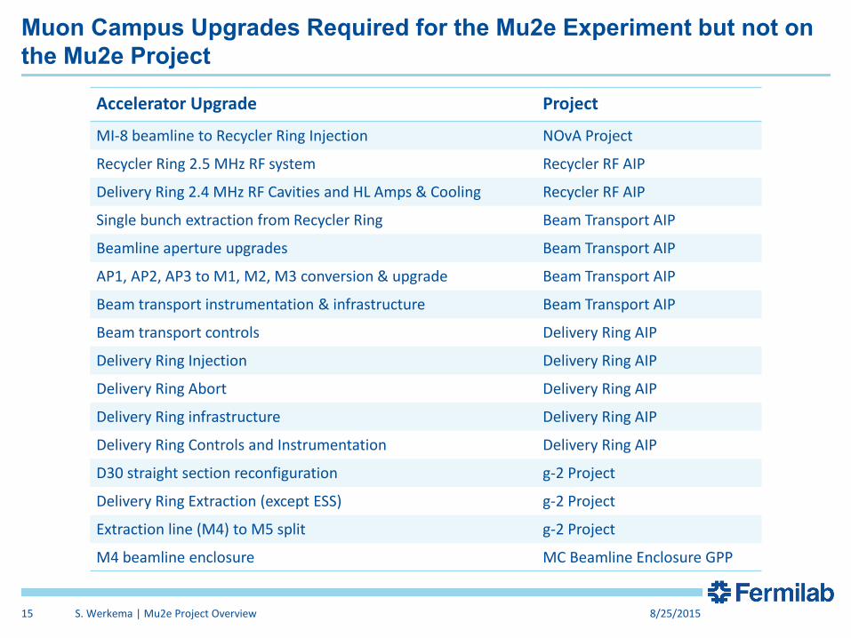
Muon Campus Upgrades Required for the Mu2e Experiment but not on the Mu2e Project
Accelerator Upgrade Project
MI-8 beamline to Recycler Ring Injection NOvA Project
Recycler Ring 2.5 MHz RF system Recycler RF AIP
Delivery Ring 2.4 MHz RF Cavities and HL Amps & Cooling Recycler RF AIP
Single bunch extraction from Recycler Ring Beam Transport AIP
Beamline aperture upgrades Beam Transport AIP
AP1, AP2, AP3 to M1, M2, M3 conversion & upgrade Beam Transport AIP
Beam transport instrumentation & infrastructure Beam Transport AIP
Beam transport controls Delivery Ring AIP
Delivery Ring Injection Delivery Ring AIP
Delivery Ring Abort Delivery Ring AIP
Delivery Ring infrastructure Delivery Ring AIP
Delivery Ring Controls and Instrumentation Delivery Ring AIP
D30 straight section reconfiguration g-2 Project
Delivery Ring Extraction (except ESS) g-2 Project
Extraction line (M4) to M5 split g-2 Project
M4 beamline enclosure MC Beamline Enclosure GPP
8/25/2015 S. Werkema | Mu2e Project Overview 15

The Mu2e Project Accelerator Systems
8/25/2015 S. Werkema | Mu2e Project Overview 16

Mu2e Accelerator Systems Scope Overview
8/25/2015 S. Werkema | Mu2e Project Overview 17
Mu2e Bldg
MC-1 Bldg
475.02.03 Instrumentation & Controls
475.02.04 Radiation Safety
475.02.05 Resonant Extraction Delivery Ring
475.02.06 Delivery Ring RF
475.02.07 External (M4) Beamline
475.02.08.02 Extinction
475.02.08.03 Extinction Monitor 475.02.09 Target Station
Everywhere
×
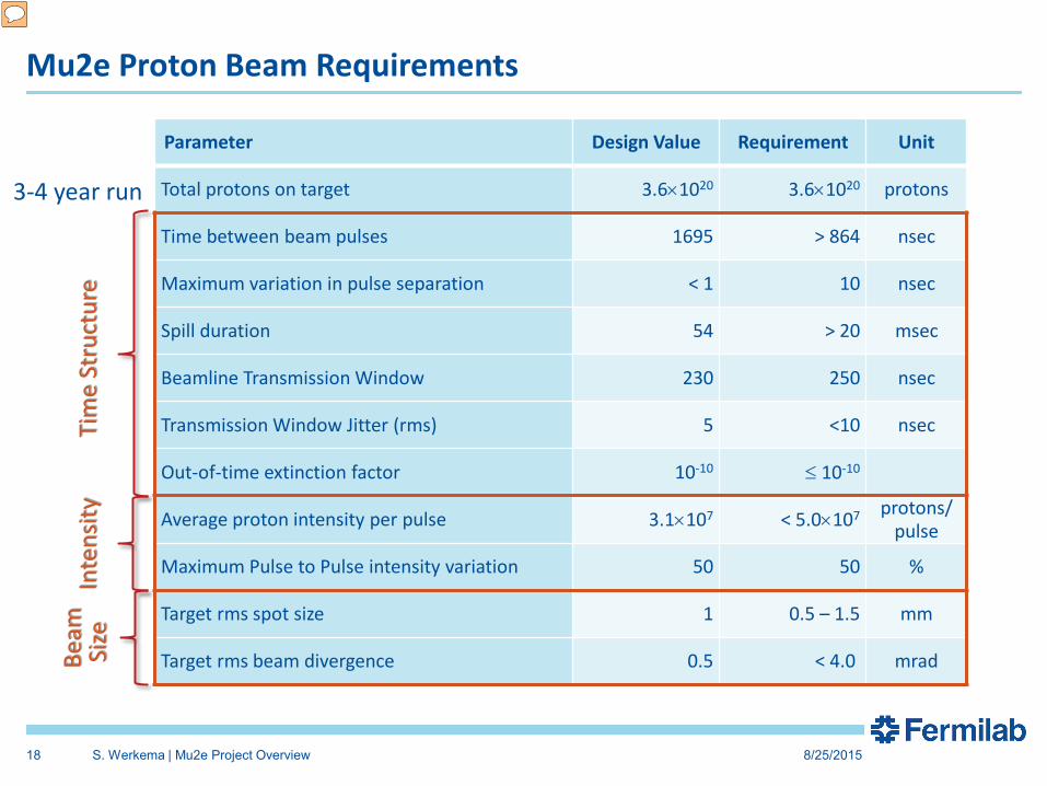
Mu2e Proton Beam Requirements
Parameter Design Value Requirement Unit
Total protons on target 3.6×10²⁰ 3.6×10²⁰ protons
Time between beam pulses 1695 > 864 nsec
Maximum variation in pulse separation < 1 10 nsec
Spill duration 54 > 20 msec
Beamline Transmission Window 230 250 nsec
Transmission Window Jitter (rms) 5 <10 nsec
Out-of-time extinction factor 10-10 ≤ 10-10
Average proton intensity per pulse 3.1×10⁷ < 5.0×10⁷ protons/ pulse
Maximum Pulse to Pulse intensity variation 50 50 %
Target rms spot size 1 0.5 – 1.5 mm
Target rms beam divergence 0.5 < 4.0 mrad
8/25/2015 S. Werkema | Mu2e Project Overview 18
Tim
e St
ruct
ure
Inte
nsity
Be
am
Size
3-4 year run

Proton Beam & Extinction Requirements
8/25/2015 S. Werkema | Mu2e Project Overview 19
(Requirement: <50 Mp/pulse)
Two successive proton pulses on the Mu2e target (out of ~30,000 per spill)

Delivery Ring Bunch Shape Variation in Time
8/25/2015 S. Werkema | Mu2e Project Overview 20
Waterfall display of the variation of the proton bunch time profile as the bunch rotates in the 2.4 MHz RF bucket. A trace is plotted every 1.35 msec over the course of the spill. The vertical axis is time relative to the start of the spill. The horizontal axis is Delivery Ring phase (1° = 4.708 nsec).
The re-bunched beam from the Recycler is poorly matched to the 2.4 MHz RF bucket in the Delivery Ring. Thus, the beam tumbles in the bucket. The bunch shape changes at twice the synchrotron frequency (Tsynch = 25.6 msec).
-94 ns 94 ns -47ns 47ns

The Mu2e Building
8/25/2015 S. Werkema | Mu2e Project Overview 21
Proton Target lives here

8/25/2015 S. Werkema | Mu2e Project Overview 22
• Target – located inside the Production Solenoid (PS)
• Heat & Radiation Shield (HRS) • Proton Absorber • Protection Collimator
PS
Mu2e Proton Target Station

M4 Enclosure Construction
8/25/2015 S. Werkema | Mu2e Project Overview 23

M4 Beamline Enclosure construction – Diagnostic Absorber
8/25/2015 S. Werkema | Mu2e Project Overview 24

Pouring Mu2e building floor slab • Looking east toward g-2 Building
8/25/2015 S. Werkema | Mu2e Project Overview 25

Framing the walls in the proton target station area of the Mu2e building
8/25/2015 S. Werkema | Mu2e Project Overview 26

Schedule
8/25/2015 S. Werkema | Mu2e Project Overview 27

Mu2e Mu2e
M4 Enclosure BO
Schedule
Q3 Q4 Q1 Q2 Q3 Q4 Q1 Q2 Q3 Q4 Q1 Q2 Q3 Q4 Q1 Q2 Q3 Q4 Q1 Q2 Q3 Q4 Q1 Q2 Q3 Q4 Q1 Q2 Q3 Q4 Q1 Q2 Q3 Q4
FY14 FY15 FY16 FY17 FY18 FY19 FY20 FY21
CD-3c CD-2/3b
Resonant Extraction Design
g-2 Beam Operations
Extinction Design
AC Dipole, Pwr Supply & Collimator Procurement, Fabrication & Install
External (M4) Beamline Design
Target Station Design HRS Procurement & Fabrication
Instrumentation & Controls Implementation
Delivery Ring RF Procurements, Fabrication & Installation
PS Arrives @ Mu2e Bldg
8/25/2015 S. Werkema | Mu2e Project Overview 28
Fabrication & Installation of Res. Extr. Magnets, Power Supplies, & Electronics
Fabricate ESS
Target Fabrication
Instrumentation & Controls Design
Radiation Safety Design
Delivery Ring RF Design
Beam to Diagnostic Absorber
Mu2e Complete
M4 Commissioning with single turn Beam
Extinction Monitor Procurement, Assembly & Install
HRS Installation
Final Focus Section Installation
Hbend Section Installation
Extinction & M4DA Section Installation
Install ESS
Radiation Safety Procurements, Fabrication & Installation
Commission Res. Extr.
Beam Operations:
Target Remote Handling Fabrication & Installation

Mu2e Mu2e
Muon Campus Program Cost
Project Total Project Cost ($M)
Accelerator Costs ($M)
Muon g-2 Project 46.4 22.2 Mu2e Project 271.0 50.2 Recycler RF AIP 9.7 9.7 Beam Transport AIP 6.2 6.2 Delivery Ring AIP 9.3 9.3 Cryo AIP 9.7 9.7 MC-1 Building GPP 9.0 Beam Enclosure GPP 9.7 MC Infrastructure GPP 1.0 1.0
Total 372.0 108.3
8/25/2015 S. Werkema | Mu2e Project Overview 29
All costs are base cost + estimate uncertainty (contingency)


