24
Mud Line Gate Valves Smart Solutions. Powerful Products. ®
1
Mud Line Gate Valves
Smart Solutions. Powerful Products.®
Introduction
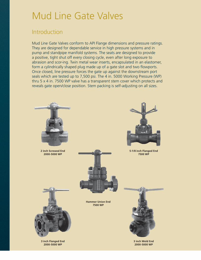
Mud Line Gate Valves conform to API Flange dimensions and pressure ratings. They are designed for dependable service in high pressure systems and in pump and standpipe manifold systems. The seats are designed to provide a positive, tight shut off every closing cycle, even after long exposure to abrasion and scor-ing. Twin metal wear inserts, encapsulated in an elastomer, form a cylindrically shaped plug made up of a gate slot and two flowports. Once closed, line pressure forces the gate up against the downstream port seals which are tested up to 7,500 psi. The 4 in. 5000 Working Pressure (WP) thru 5 x 4 in. 7500 WP valve has a transparent stem cover which protects and reveals gate open/close position. Stem packing is self-adjusting on all sizes.
2 inch Screwed End2000-5000 WP
Hammer Union End 7500 WP
3 inch Flanged End2000-5000 WP
3 inch Weld End2000-5000 WP
5-1/8 inch Flanged End7500 WP
Mud Line Gate Valves

1
General Application• Water, oil, and gas lines• Wellheads• Pipelines and manifolds• Abrasive drilling mud• Sour gas and crude oil• Up to 7,500 psi and temperature range of -40°F to 400°F
STANDARD TRIM INCLUDES• A-487 Steel Body and Bonnet• Stainless Steel (SS) Stem and Gate• Steel Buna-N Seats• 90 Durometer A Buna-N Seals
Sizes• Full Port - 2 in., 3 in., 4 in., 4-1/16 in., and 5-1/8 in.• Regular Port - 5 x 4 in., 6 x 4 in., and 6 x 5 in.
Material Traceability** Certification provided upon request at additional charge.
• DNV• Lloyd’s of London Type Approval• PSL 1 and 2
Connections• Screwed End• Weld End• Ring Type Joint (RTJ), Flanged End• Integral Hammer Union
Testing and Pressure RatingsAll Mud Gate Valves are hydrostatically tested.
Working Pressure (WP) Shell Test Pressure
3000 WP 4,500 psi Test
5000 WP 7,500 psi Test
7000 WP 11,250 psi Test
General Information

2
Dimensions and Pressure Ratings3000 AND 5000 WP
Note: These diagrams are for dimensional purposes only. For actual product illustrations, refer to pages 14, 16, and 20.
A Screwed-End Body Flanged-End Body
Weld-End Body
Pressure Rating 3000 WP 6000 PSI Test 5000 WP 10000 PSI Test
Size2 3 4
4-1/16 2 3 4 4-1/16 5x4 6x4
inch inch inch inch inch inch inch inch
A
Screwed End 9 11 13 9 11 13 13 N/A
Weld End 9 11 13 9 11 13 13 13
Flanged End 11-5/8 14-1/8 16-3/8 12-1/8 15-5/8 18 29 N/A
B (Open) 13 18 21-1/4 13 18 24-5/8 24-5/8 24-5/8
C (Seat Bore) 2 3 4 2 3 4 4 4
D (Handle Diameter) 14 19 23 14 19 23 23 23
F
(Flange Diameter) 8-1/2 9-1/2 11-1/2 8-1/2 10-1/2 12-1/4 14-3/4 N/A
Flange Bolts (Qty) (8) (8) (8) (8) (8) (8) (8) N/A
Size 7/8 7/8 1-1/8 7/8 1-1/8 1-1/4 1-1/2 N/A
Ring No. (RTJ) R24 R31 R37 R24 R35 R39 R44 N/A
N/A = Not Available.
A
C
D
B
A
C
D
B
A
CF
D
B

3
BASE MATERIAL NUMBER1st to 3rd Digits
Full Port - 930 API 6A ID - 932
Regular Port - 934
Materials Number Scheme
• 7,500 WP only.* 7,500 WP is available in SCHXXH only.
DigitCode 10th Digit
DigitCode 11th Digit
DigitCode 12th Digit
Description Description Description
0 Not Required 0 Not Required 0 Not Required
6 Q.A and Testing to API 6D only (Same requirements as “D” certified)
1 PSL 1 Requirements B I.R.C. - Independent Design Review Certificate
2 PSL 2 Requirements
A Statement of Compliance Hydrostatic Test Report
3 PSL 3 Requirements - with Amendment N NACE MR0175 Documentation
4 PSL 2 Requirements - with PSL 1 Test
B Statement of Compliance Mill Certs Hydrostatic Test Report
5 PSL 1 Requirements - with M.P.I. S I.R.C. and NACE MR0175 Documentation
6 PSL 1 Requirements - DYE Penetrant T 3rd Party Inspection
7 Standard Testing - PSL 1 Requirements MPI and DYE Penetrant
U 3rd Party Inspection and I.R.C.
C Statement of Compliance Mill Certs Hydrostatic Test Report Charpy Impacts-Pressure Containing Part
D Standard Testing - DYE Penetrant V 3rd Party Inspection and NACE
M Standard Testing - Magnetic Particle Inspection (MPI)
W 3rd Party Inspection/I.R.C./NACE MR0175 Documentation
D Statement of Compliance Mill Certs Hydrostatic Test Report Charpy Impacts-Pressure Containing Part Hydrostatic Test Chart
P Standard Testing - DYE Penetrant and MPI
R Standard Testing - Radiograph X Special
T Standard Testing - PSL 2 Requirements MPI, DYE Penetrant and Hardness
Note: For Non-Standard Assemblies, 7th through 12th digits will be assigned.
SIZE5th Digit(2 in. - 1)
(3 in. -3) (4 in., 4-1/16 in. - 4)(5 x 4 in. - 4), (5-1/8 in., 6 x 4 in. - 5)
(6 x 5-1/8 in. - 8)
BODY MATERIAL9th Digit
No Coating - 0 SPECIAL - X
GATE/STEM MATERIAL7th Digit
316 SS/316 SS Stem - 3316 SS with Tungsten Carbide
Coating/316 SS Stem - 4•17-4 PH/316 SS Stem - 5•17-4 PH/410 SS Stem - 6•
WORKING PRESSURE4th Digit
3000 - 55000 - 67500 - 8
END CONNECTION6th Digit
SEAT MATERIAL8th Digit
Screwed LP-0, NUE-1, EUE-2, Short/Long Casing Thread-EWeld: XXH-4*, SCH 160-5Flanged: RTJ-7Hammer Union: 1002 - N 1502 - P
NBR Viton® HSN 85DPC 90D Buna-N•Steel B N/A N/A J316 SS M N Z N/A410 SS N/A N/A N/A P
I IX X X
I
IXXX X
I
IX X
I
4
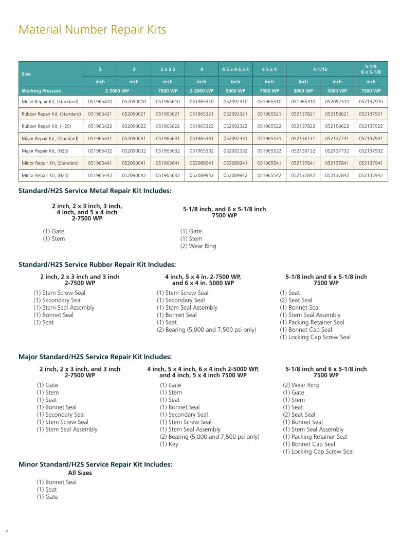
Material Number Repair Kits
Size2 3 2 x 3 3 4 4 5 x 4 6 x 4 4 5 x 4 4-1/16 5-1/8
6 x 5-1/8
inch inch inch inch inch inch inch inch inch
Working Pressure 2-5000 WP 7500 WP 2-3000 WP 5000 WP 7500 WP 3000 WP 5000 WP 7500 WP
Metal Repair Kit, (Standard) 051965410 052090010 051965610 051965310 052092310 051965510 051965310 052092310 052137910
Rubber Repair Kit, (Standard) 051965421 052090021 051965621 051965321 052092321 051965521 052137821 052150621 052137921
Rubber Repair Kit, (H2S) 051965422 052090022 051965622 051965322 052092322 051965522 052137822 052150622 052137922
Major Repair Kit, (Standard) 051965431 052090031 051965631 051965331 052092331 051965531 052136131 052137731 052137931
Major Repair Kit, (H2S) 051965432 052090032 051965632 051965332 052092332 051965532 052136132 052137732 052137932
Minor Repair Kit, (Standard) 051965441 052090041 051965641 052089941 052089941 051965541 052137841 052137841 052137941
Minor Repair Kit, (H2S) 051965442 052090042 051965642 052089942 052089942 051965542 052137842 052137842 052137942
Major Standard/H2S Service Repair Kit Includes:
2 inch, 2 x 3 inch, and 3 inch2-7500 WP
4 inch, 5 x 4 inch, 6 x 4 inch 2-5000 WP,and 4 inch, 5 x 4 inch 7500 WP
5-1/8 inch and 6 x 5-1/8 inch7500 WP
(1) Gate (1) Gate (2) Wear Ring(1) Stem (1) Stem (1) Gate(1) Seat (1) Seat (1) Stem(1) Bonnet Seal (1) Bonnet Seal (1) Seat(1) Secondary Seal (1) Secondary Seal (2) Seat Seal(1) Stem Screw Seal (1) Stem Screw Seal (1) Bonnet Seal(1) Stem Seal Assembly (1) Stem Seal Assembly (1) Stem Seal Assembly
(2) Bearing (5,000 and 7,500 psi only) (1) Packing Retainer Seal(1) Key (1) Bonnet Cap Seal
(1) Locking Cap Screw Seal
Standard/H2S Service Metal Repair Kit Includes:
2 inch, 2 x 3 inch, 3 inch,4 inch, and 5 x 4 inch
2-7500 WP
5-1/8 inch, and 6 x 5-1/8 inch7500 WP
(1) Gate (1) Gate(1) Stem (1) Stem
(2) Wear Ring
Standard/H2S Service Rubber Repair Kit Includes:
2 inch, 2 x 3 inch and 3 inch2-7500 WP
4 inch, 5 x 4 in. 2-7500 WP,and 6 x 4 in. 5000 WP
5-1/8 inch and 6 x 5-1/8 inch7500 WP
(1) Stem Screw Seal (1) Stem Screw Seal (1) Seat(1) Secondary Seal (1) Secondary Seal (2) Seat Seal(1) Stem Seal Assembly (1) Stem Seal Assembly (1) Bonnet Seal(1) Bonnet Seal (1) Bonnet Seal (1) Stem Seal Assembly(1) Seat (1) Seat (1) Packing Retainer Seal
(2) Bearing (5,000 and 7,500 psi only) (1) Bonnet Cap Seal(1) Locking Cap Screw Seal
Minor Standard/H2S Service Repair Kit Includes:All Sizes
(1) Bonnet Seal(1) Seat(1) Gate

5
Parts and Weights2 inch - 3000 and 5000 WP
Item No. Description
2 inch
3000 WP 5000 WP
1 Lube Fitting Steel
WWW00C000 (0.1 lb)
2 Hub Assembly Steel
051888000 (5 lb)
3 Pin, Lock Handle Steel
WWLC16204 (0.1 lb)
4 Lock Handle Steel
051888400 (2 lb)
5 CouplingWCB Steel
051888809 (10 lb)
6Stem Screw Seal 70 D Buna-N H30 WWB224XXX
(0.5 lb)75 D Viton® V35
7 Screw Housing Steel
051882500 (4 lb)
8 Lock Screw Steel
WWG11B080 (0.1 lb)
9 Stem Screw Steel
051882400 (2 lb)
10Secondary Seal 90 D Buna-N H30 WWB210XXX
(0.2 lb)Buna-N 90 D Viton® V40
11 Retainer Steel 051882600 (0.5 lb)
12 Stem Seal Assembly 105312722 (0.2 lb)
13 Bonnet (AISI 1029 Steel) None 9 05188892X(8 lb)
14 Stem 316 SS
051816008 (1.5 lb)
15 Gate 316 SS
051815908 (2.3 lb)
16
Seat 0518204XX (1.5 lb)(1.5 Ib)(1.5 Ib)(1.5 lb)(1.5 lb)
Steel 70 D Buna-N 21
316 SS 70 D Buna-N 81
90 D Viton® 82
90 DPC 86
17
Bonnet Seal WWB342XXX(0.1 lb)(0.1 lb)(0.1 lb)
90 D Buna-N H40
90 D Viton® V40
90 DPC P41
18 Index Pin Steel
WWLA1B0S4 (0.1 lb)
19
Body Uncoated Steel 051884709 (27 lb)
051885809 (26 lb)
Screwed End LP
EUE
Flanged End RTJ 051887420 (67 lb)
051887739 (79 lb)
Weld End
O/ASCH 80 1
SCH XXH 2
SCH 160 5
Grooved End SCH 80 N/A
***Body Coatings***
–
Change last digit to:
None 9
Baker 10 6
Baker 11 7
Baker 12 8
O/A = On Application.
1
9
6
4
2
3
2
5
12
11
10 8
14
13
17
19
15
18
16

6
Parts and Weights3 inch, 4 inch and 4-1/16 inch - 3000 WP
Item No. Description
3 inch 4 inch 4-1/16 inch
3000 WP
1 Lube Fitting, Steel WWW00C000 (0.1 lb)
2Hub Assembly 051888100
(7.5 lb)051888200
(7.5 lb)Steel
3 Pin, Lock Handle, Steel WWLC16204 (0.1 Ib)
4Lock Handle 051888500
(2 lb)051888600
(2.5 Ib)Steel
6Stem Screw Seal 70 D Buna-N H30 WWB226XXX
(0.1 Ib)WWB227XXX
(0.1 Ib)75 D Viton® V40
7Screw Housing 051884000
(5 lb)051883300
(7 lb)Steel
9Stem Screw 051883900
(3 lb)051883100
(4 lb)Steel
10Secondary Seal 90 D Buna-N H30 WWB212XXX
(0.2 lb)WWB214XXX
(0.2 lb)90 D Viton® H40
11Retainer 051883800
(0.5 lb)051882700
(0.5 lb)Steel
12 Stem Seal Assembly 105312732(0.5 lb)
105312742(0.5 lb)
13 Bonnet (A-487 Steel) 051889239(29 lb)
051889339(37 lb)
052092120(37 lb)
14Stem 051818708
(2 lb)051820708
(2 lb)051820702
(2 lb)316 SS-08 303SS-02
15Gate 051818808
(5 lb)051820108
(9 lb)316 SS
16
Seat 0518206XX 0518205XX 0520925XXSteel 70 D Buna-N 21 (6 lb) (8 lb) (8 lb)316 SS 70 D Buna-N 81 (6 lb) (8 lb) (8 lb)
90 D Viton® 82 (6 lb) (8 lb) (8 lb)90 DPC 86 (6 lb) (8 lb) (8 lb)
17
Bonnet Seal WWB433XXX WWB439XXX90 D Buna-N H40 (0.2 lb) (0.2 lb)90 D Viton® V40 (0.2 lb) (0.2 lb)90 DPC P41 (0.2 lb) (0.2 lb)
19
Body Screwed End Uncoated SteelLP 051884539 051884639 N/A
(70 lb) (80 lb) N/ANUE 051885239 051885339 N/A
(70 lb) (80 lb) N/AEUE 051922929 N/A N/A
(70 lb) N/A N/ALong/Short Casing Thread N/A N/A 052092220
N/A N/A (80 lb)Flanged End RTJ O/A O/A N/A
O/A O/A N/AWeld End SCH 80 1 O/A O/A N/A
SCH XXH 2 O/A O/A N/ASCH 160 5 O/A O/A N/A
Grooved End SCH 80 N/A O/A O/A N/A
20Bonnet Stud (2 Required) WWHS1S2S6
(1.5 Ib)WWHS1W3H6
(1.5 Ib)A-320-L7 Steel Each
21Bonnet Stud Nut (2 Required) WWJA1S10Z
(0.5 lb)WWJA1W10Z
(0.5 lb)A-320-L7 Steel Each
22Body Stud (4 Required) WWHS203H6
(2 lb)WWHS284H6
(2 lb)A-320-L7 Steel Each
23Body Stud Nut (4 Required) WWJA2010Z
(1 lb)WWJA2810Z
(1 lb)A-320-L7 Steel Each
24Bleeder Plug N/A
N/AN/AN/A
WWS120HFS(1 lb)
N/A = Not Available.; O/A = On Application; Bleeder Plug not shown. Refer to page 16 for product illustration.
1
9
6
4
2
3
5
12
11
10
7
14
15
17
16
21
20
23
13
19
22
7
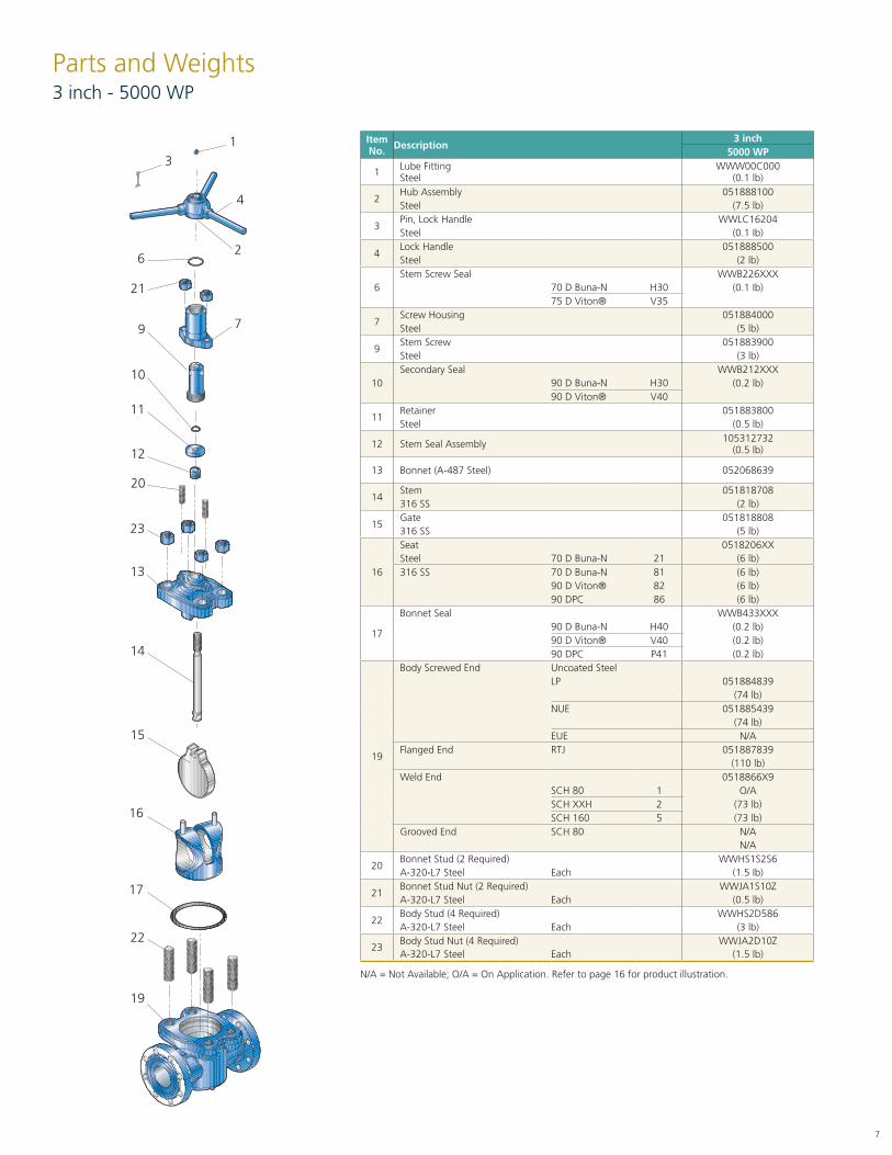
Parts and Weights3 inch - 5000 WP
N/A = Not Available; O/A = On Application. Refer to page 16 for product illustration.
Item No. Description
3 inch5000 WP
1 Lube FittingSteel
WWW00C000(0.1 lb)
2Hub Assembly 051888100Steel (7.5 lb)
3Pin, Lock Handle WWLC16204Steel (0.1 Ib)
4Lock Handle 051888500Steel (2 lb)
6Stem Screw Seal WWB226XXX
70 D Buna-N H30 (0.1 Ib)75 D Viton® V35
7Screw Housing 051884000Steel (5 lb)
9Stem Screw 051883900Steel (3 lb)
10Secondary Seal WWB212XXX
90 D Buna-N H30 (0.2 lb)90 D Viton® V40
11Retainer 051883800Steel (0.5 lb)
12 Stem Seal Assembly 105312732(0.5 lb)
13 Bonnet (A-487 Steel) 052068639
14Stem 051818708316 SS (2 lb)
15Gate 051818808316 SS (5 lb)
16
Seat 0518206XXSteel 70 D Buna-N 21 (6 lb)316 SS 70 D Buna-N 81 (6 lb)
90 D Viton® 82 (6 lb)90 DPC 86 (6 lb)
17
Bonnet Seal WWB433XXX90 D Buna-N H40 (0.2 lb)90 D Viton® V40 (0.2 lb)90 DPC P41 (0.2 lb)
19
Body Screwed End Uncoated SteelLP 051884839
(74 lb)NUE 051885439
(74 lb)EUE N/A
Flanged End RTJ 051887839(110 lb)
Weld End 0518866X9SCH 80 1 O/ASCH XXH 2 (73 lb)SCH 160 5 (73 lb)
Grooved End SCH 80 N/AN/A
20Bonnet Stud (2 Required) WWHS1S2S6A-320-L7 Steel Each (1.5 Ib)
21Bonnet Stud Nut (2 Required) WWJA1S10ZA-320-L7 Steel Each (0.5 lb)
22Body Stud (4 Required) WWHS2D586A-320-L7 Steel Each (3 lb)
23Body Stud Nut (4 Required) WWJA2D10ZA-320-L7 Steel Each (1.5 lb)
1
9
6
4
2
3
5
12
11
10
7
14
15
17
16
21
20
23
13
19
22
8
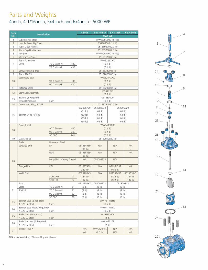
Parts and Weights4 inch, 4-1/16 inch, 5x4 inch and 6x4 inch - 5000 WP
N/A = Not Available; *Bleeder Plug not shown.
Item No. Description
4 inch 4-1/16 inch 5 x 4 inch 6 x 4 inch
5000 WP
1 Lube Fitting, Steel WWW00C000 (0.1 lb)2 Handle Assembly, Steel 051888300 (11 lb)3 Tube, Clear Acrylic 051889600 (0.2 lb)4 Stem Cap Ductile Iron 051889700 (2.5 lb)5 Key Steel WWW00A000 (0.5 lb)6 Stem Screw Steel 051883200 (5 lb)
7Stem Screw Seal WWB226XXXSteel 70 D Buna-N H30 (0.1 Ib)
75 D Viton® V35 (0.1 Ib)
8 Screw Housing, Steel 051883400 (8 lb)9 Stem 316 SS 051820208 (3 lb)
10Secondary Seal WWB214XXX
90 D Buna-N H30 (0.2 lb)90 D Viton® V40 (0.2 lb)
11 Retainer Steel 051882800 (1 lb)
12 Stem Seal Assembly105312742
(0.5 lb)
13Bearing (2 Required) 051883000Teflon®/Phenolic Each (0.1 lb)
14 Down Stop Ring, 303SS 051882900 (0.5 lb)
16 Bonnet (A-487 Steel)
052096729 051889539 052096729(61 lb) (61 lb) (61 lb)(63 lb) (63 lb) (63 lb)(65 lb) (65 lb) (65 lb)(68 lb) (68 lb) (68 lb)
18
Bonnet Seal WWB439XXX90 D Buna-N H40 (0.2 lb)90 D Viton® V40 (0.2 lb)90 DPC P41 (0.2 lb)
19 Gate 316 SS 051820108 (9 lb)
20
Body Uncoated SteelScrewed End LP 051884939 N/A N/A N/A
(130 lb) – – –
NUE 051885539 N/A N/A N/A(130 lb) – – –
Long/Short Casing Thread N/A 052098220 N/A– – –
Flanged End RTJ 051887939 N/A 051964239 N/A(230 lb) – (485 lb) –
Weld End 0520763X9 N/A 0519994X9 0519310X9SCH XXH 2 (134 lb) – (134 lb) (134 lb)SCH 160 5 (132 lb) – (132 lb) (132 lb)
21
Seat 0518205XX 052092521 0518205XXSteel 70 D Buna-N 21 (8 lb) (8 lb) (8 lb)
316 SS 70 D Buna-N 81 (8 lb) (8 lb) (8 lb)90 D Viton® 82 (8 lb) (8 lb) (8 lb)90 DPC 86 (8 lb) (8 lb) (8 lb)
23Bonnet Stud (2 Required) WWHS1W3H6A-320-L7 Steel Each (1.5 Ib)
24Bonnet Stud Nut (2 Required) WWJA1W10ZA-320-L7 Steel Each (0.5 lb)
25Body Stud (4 Required) WWHS2S606A-320-L7 Steel Each (4 lb)
26Body Stud Nut (4 Required) WWJA2S10Z
A-320-L7 Steel Each (2 lb)
27Bleeder Plug * N/A WWS120HFS N/A N/A
N/A (1.0 lb) N/A N/A
81
6
4
2
3
5
12
11
10
7
9
19
25
21
24
26
23
16
20
13
13
6
5
14
18

9
Materials Specifications
Item
2000/3000/5000 WP
2 inch, 3 inch, 4 inch, 4-1/16 inch,5 x 4 inch and 6 x 4 inch
Body
Screwed/Grooved A-487 Cast Steel
Weld A-487 Cast Steel
Flanged A-487 Cast Steel
Bonnet A-487 Cast Steel
Coupling A-487 Cast Steel
Stem 316 Stainless Steel
Seat
Elastomer 70 Durometer A Buna-N
Insert A-216 Cast Steel
Gate 316 Stainless Steel
Studs A-320-L7 Steel
Nuts A-320-L7 Steel
Optional Trims
Seat
Elastomer 90 Durometer A Peroxide Cured Buna-N or
90 Durometer A Fluoroelastomer
Insert 316 Stainless Steel
Studs A-193-B7M
Nuts A-194-2HM Steel
PropertiesBase Elastomer
NBR Fluoroelastomer HSN
Durometer A 70PC 90PC 90 85
Temperature Range, FahrenheitHigh +225 +225 +400 +300
Low -30 0 -20 -25
Hydrogen Sulfide, H2SHot Poor Fair Good Best
Cold Fair Fair Good Best
Carbon Dioxide, CO2Wet Fair Good Fair Best
Dry Fair Good Fair Best
Dilute Acidics Good Good Good Good
Dilute Caustics Fair Fair Good Good
Sour Oil and Gas C/E C/E C/E C/E
Salt Water Best Good Good Good
Oil Best Good Good Good
Sweet Gas Good Best Good Good
C/E - Consult Engineering.PC - Peroxide Cured.
Elastomer Properties and Selection
Item
3000/5000 WP
2 inch, 3 inch, 4 inch, 4-1/16 inch,5 x 4 inch and 6 x 4 inch
Body
Screwed/Grooved A-487 Cast Steel
Weld A-487 Cast Steel
Flanged A-487 Cast Steel
Bonnet A-487 Cast Steel
Coupling A-487 Cast Steel
Stem 316 Stainless Steel
Seat
Elastomer 70 Durometer A Buna-N
Insert A-216 Cast Steel
Gate 316 Stainless Steel
Studs A-320-L7 Steel
Nuts A-320-L7 Steel

10
A
C
D
B
Dimensions and Pressure Rating 7500 WP
N/A = Not Available. O/A = On Application.
Dim
Pressure Rating 7500 WP and 11250 WP Test
Size2 x 3 3 4 5 x 4 5-1/8 6 x 5-1/8
inch inch inch inch inch inch
A
Screwed End N/A N/A N/A N/A N/A N/A
Weld End 11 11 13 13 N/A 18
Flanged End 18.38 24.38 26.38 N/A 29 N/A
Hammer Union 150217.87 TBD 1002
19.25100223.25 N/A TBD
B (Open) 13 18 24-5/8 24-5/8 31-3/4 31-3/4
C (Seat Bore) 2 3 4 4 5-1/8 5-1/8
D (Handle Diameter) 14 19 23 23 24 24
F
(Flange Diameter) 8-1/2 10-1/2 12-1/4 14-3/4 14-1/16 N/A
Flange Bolts (Qty) (8) (12) N/A
Size 7/8 1-1/8 1-1/4 1-1/2 1-1/8 N/A
Ring No. (RTJ) BX-152 BX-154 BX-155 N/A BX-169 N/A
Weld-End Body
Hammer Union End Flanged End
A
C
D
B
F
A
D
B
F C
11
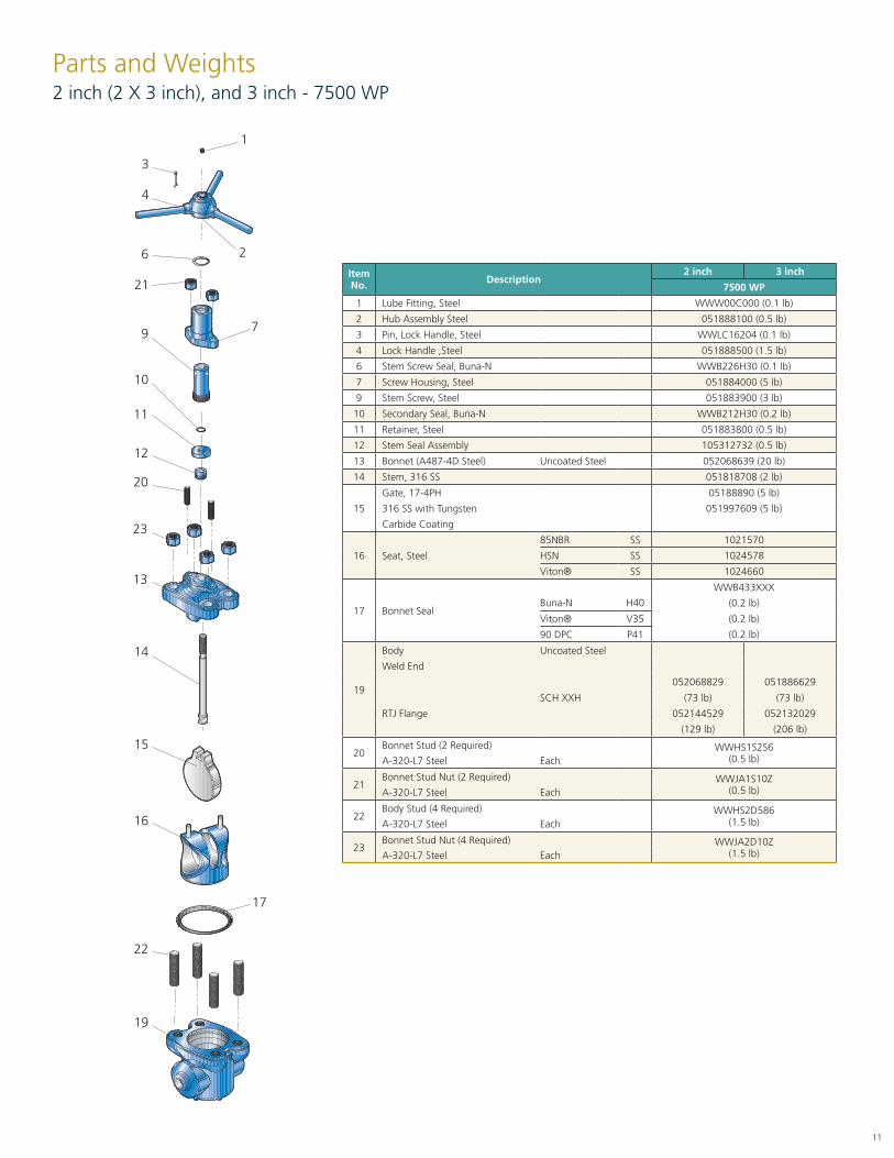
Parts and Weights2 inch (2 X 3 inch), and 3 inch - 7500 WP
Item No. Description
2 inch 3 inch
7500 WP
1 Lube Fitting, Steel WWW00C000 (0.1 lb)
2 Hub Assembly Steel 051888100 (0.5 lb)
3 Pin, Lock Handle, Steel WWLC16204 (0.1 lb)
4 Lock Handle ,Steel 051888500 (1.5 lb)
6 Stem Screw Seal, Buna-N WWB226H30 (0.1 lb)
7 Screw Housing, Steel 051884000 (5 lb)
9 Stem Screw, Steel 051883900 (3 lb)
10 Secondary Seal, Buna-N WWB212H30 (0.2 lb)
11 Retainer, Steel 051883800 (0.5 lb)
12 Stem Seal Assembly 105312732 (0.5 lb)
13 Bonnet (A487-4D Steel) Uncoated Steel 052068639 (20 lb)
14 Stem, 316 SS 051818708 (2 lb)
15
Gate, 17-4PH 05188890 (5 lb)
316 SS with Tungsten 051997609 (5 lb)
Carbide Coating
16 Seat, Steel
85NBR SS 1021570
HSN SS 1024578
Viton® SS 1024660
17 Bonnet Seal
WWB433XXX
Buna-N H40 (0.2 lb)
Viton® V35 (0.2 lb)
90 DPC P41 (0.2 lb)
19
Body Uncoated Steel
Weld End
052068829 051886629
SCH XXH (73 lb) (73 lb)
RTJ Flange 052144529 052132029
(129 lb) (206 lb)
20Bonnet Stud (2 Required) WWHS1S2S6
(0.5 Ib)A-320-L7 Steel Each
21Bonnet Stud Nut (2 Required) WWJA1S10Z
(0.5 lb)A-320-L7 Steel Each
22Body Stud (4 Required) WWHS2D586
(1.5 lb)A-320-L7 Steel Each
23Bonnet Stud Nut (4 Required) WWJA2D10Z
(1.5 lb)A-320-L7 Steel Each
9
6
3
2
1
12
11
10
7
14
15
17
16
21
20
23
13
19
22
4
12
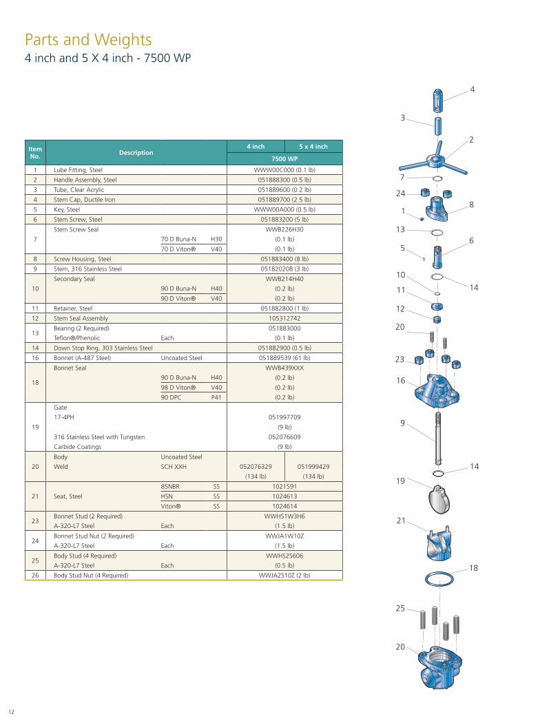
Parts and Weights4 inch and 5 X 4 inch - 7500 WP
ItemNo. Description
4 inch 5 x 4 inch
7500 WP
1 Lube Fitting, Steel WWW00C000 (0.1 lb)
2 Handle Assembly, Steel 051888300 (0.5 lb)
3 Tube, Clear Acrylic 051889600 (0.2 lb)
4 Stem Cap, Ductile Iron 051889700 (2.5 lb)
5 Key, Steel WWW00A000 (0.5 lb)
6 Stem Screw, Steel 051883200 (5 lb)
7
Stem Screw Seal WWB226H30
70 D Buna-N H30 (0.1 lb)
70 D Viton® V40 (0.1 lb)
8 Screw Housing, Steel 051883400 (8 lb)
9 Stem, 316 Stainless Steel 051820208 (3 lb)
10
Secondary Seal WWB214H40
90 D Buna-N H40 (0.2 lb)
90 D Viton® V40 (0.2 lb)
11 Retainer, Steel 051882800 (1 lb)
12 Stem Seal Assembly 105312742
13Bearing (2 Required) 051883000
Teflon®/Phenolic Each (0.1 lb)
14 Down Stop Ring, 303 Stainless Steel 051882900 (0.5 lb)
16 Bonnet (A-487 Steel) Uncoated Steel 051889539 (61 lb)
18
Bonnet Seal WWB439XXX
90 D Buna-N H40 (0.2 lb)
98 D Viton® V40 (0.2 lb)
90 DPC P41 (0.2 lb)
19
Gate
17-4PH 051997709
(9 lb)
316 Stainless Steel with Tungsten 052076609
Carbide Coatings (9 lb)
20
Body Uncoated Steel
Weld SCH XXH 052076329 051999429
(134 lb) (134 lb)
21 Seat, Steel
85NBR SS 1021591
HSN SS 1024613
Viton® SS 1024614
23Bonnet Stud (2 Required) WWHS1W3H6
A-320-L7 Steel Each (1.5 Ib)
24Bonnet Stud Nut (2 Required) WWJA1W10Z
A-320-L7 Steel Each (1.5 Ib)
25Body Stud (4 Required) WWHS2S606
A-320-L7 Steel Each (0.5 lb)
26 Body Stud Nut (4 Required) WWJA2S10Z (2 lb)
136
3
2
1
12
11
5
7
9
19
18
21
24
20
23
16
20
25
4
8
10
14
14
13
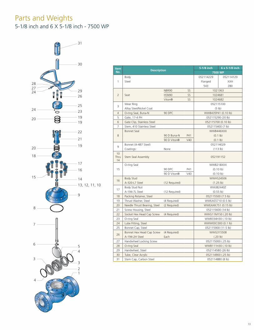
Item No. Description
5-1/8 inch 6 x 5-1/8 inch
7500 WP
1
Body 052114229 052114129
Steel Flanged XXH
543 280
2 Seat
NBR90 SS 1021363
HSN90 SS 1024681
Viton® SS 1024682
3Wear Ring 052115100
Alloy Steel/Nickel Coat (5 lb)
4 O-ring Seal, Buna-N 90 DPC WWB435P41 (0.10 lb)
5 Gate, 17-4 PH 052115290 (20 lb)
6 Gate Clip, Stainless Steel 052115700 (0.10 lb)
7 Stem, 410 Stainless Steel 052115400 (7 lb)
8
Bonnet Seal WWB446XXX
90 D Buna-N P41 (0.1 lb)
90 D Viton® V40 (0.1 lb)
9Bonnet (A-487 Steel) 052114029
Coatings: None (113 lb)
10Thru 14
Stem Seal Assembly 052191152
15
O-ring Seal WWB218XXX
90 DPC P41 (0.10 lb)
90 D Viton® V40 (0.10 lb)
16Body Stud WWHS24506
A-320-L7 Steel (12 Required) (1.25 lb)
17Body Stud Nut WWJB2440Z
A-194-7L Steel (12 Required) (0.55 lb)
18 Packing Retainer, Steel 052115500 (7.5 lb)
19 Thrust Washer, Steel (4 Required) WWEAS5710 (0.5 lb)
20 Needle Thrust Bearing, Steel (2 Required) WWEAXK751 (0.15 lb)
21 Screw Housing, Steel 052115600 (14 lb)
22 Socket Hex Head Cap Screw (4 Required) WWG11M1S0 (.20 lb)
23 O-ring Seal WWB334H30 (.10 lb)
24 Lube Fitting, Steel WWW00C000 (0.1 lb)
25 Bonnet Cap, Steel 052115900 (11.5 lb)
26Bonnet Hex Head Cap Screw (4 Required) WWG31S508
A-194-2H Steel Each (.20 lb)
27 Handwheel Locking Screw 052115000 (.25 lb)
28 O-ring Seal WWB111H30 (.10 lb)
29 Handwheel, Steel 0521145B0 (26 lb)
30 Tube, Clear Acrylic 052114900 (.25 lb)
31 Stem Cap, Carbon Steel 0521148B0 (8 lb)
Parts and Weights5-1/8 inch and 6 X 5-1/8 inch - 7500 WP
2425
30
24
15
18
20
28
9
19
5
3
27
8
7
6
4
31
29
20
26
23
19
21
22
19
17
16
14
13, 12, 11, 10
2
3
4
1

14
Repair Instructions2 inch - 3000 WP and 5000 WP Gate Valve
TOOLS REQUIRED FOR ASSEMBLY• Hammer and mandrel or metal bar• Drill and #44 bit• Adjustable pipe wrench• Torque, impact or socket wrench and socket• Grease gun and grease, molybdenum disulfide base
• Grinder with flapper wheel• Pressure test facility and fixtures• 5/16 in. Nut Driver• Vise Grips
Assembly Proceduresa. Slide the threaded end of the Stem (14) through the Bonnet
Bore (13), from the underside and place the Stem Seal Assembly (12) over the Stem. This assembly consists of the Seal Rings, a flat-backed follower ring and a Bushing, which are placed over the end of the Stem in that order. Slide the Retainer (11) with an O-ring Seal (10) in- side, over the Stem. Observe that the lips of the O-ring Seal do not get curled back. Seat the Stem Seal Assembly into its counterbore in the Bonnet.
b. Engage the Stem Screw (9) in the Screw Housing (7) about half its total travel and place the Screw Housing on the Bonnet and Stem.
c. Using vice grips, attach to Tee-Head of Stem, then rotate clockwise until Stem is above lugs so the gate can be attached. Remove vice grips and attach gate to Tee-Head. Rotate the gate to the opening between the lugs. Place the assembly on its side with the lock set screw facing up and using the lock set screw as a marker, turn counter clock- wise three times at 360° each.
d. Install lock screw, tighten, and then install the seat onto the gate. Install the Bonnet seal and Item No. pin into the body. Grease the outside of the seat and the inside of the body. Install the Bonnet as- sembly into the body. Install the coupling over the Bonnet and
tighten onto the body with a pipe wrench. Install the handle hub on the Stem Screw and insert the lock handle retainer lock with the lock handle pin. Do not spread the cotter pin at this time. Close the gate valve until the hub is resting on the top of the Screw Housing. At this point, mark the gate with a pencil at the bottom of the seat bore. Raise the bottom of the gate by turning the handle counter clockwise until half open. Measure the mark on the gate to verify the gate is fully down at 5/16 in. to 7/16 in. If the distance is cor- rect, then fully open the gate valve, spread the cotter and insert the drift bar pin. If correct, go to step F.
e. If not correct, then remove the handle and cou- pling from Bonnet assembly. Remove Bonnet as- sembly from the body. Remove the lock screw from the Stem Screw Housing and adjust the tim- ing by rotating the Stem Screw clockwise to increase distances or counter clockwise to decrease distances. Repeat step D.
f. When the Baker Mud Gate Valve is assembled in the manner described, the Hub is stopped by the Screw Housing at the proper down position of the Gate. By this design, overtightening is impossible and maximum sealing efficiency is assured.
15
Repair Instructions3 inch, 4 inch, and 4-1/16 inch - 3000 WP and 3 inch - 5000 WP Gate Valve
Assembly Proceduresa. Slide the threaded end of the Stem (14) through the Bonnet Bore
(13) from the underside and place the Stem Seal Assembly (12) over the Stem. This assembly consists of the Seal Rings, a flat-backed follower Ring and a Bushing which are placed over the end of the Stem in that order. Slide the Retainer (11) with O-ring Seal (10) inside over the Stem. Observe that the lips of the Ring do not get curled back. Seat the Stem Seal Assembly into its counterbore in the Bonnet. Install Bonnet Studs (20).
b. Engage the Stem Screw (9) in the Screw Housing(7) about half [1/2] its total travel and place the Screw Housing on the Bonnet and Stem. Replace Nuts (21).
c. Rotate the Stem Screw clockwise until it bottoms on the Retainer, then back it up approximately 45 degrees. Engage the Gate (15) on the Tee-Head of the Stem and turn them together counter clock- wise until the Gate touches the underside of the Bonnet Lugs. Align the Gate with the opening be- tween the Lugs and retract it into the Bonnet by turning the Stem Screw counter clockwise. Place the Hub (2) on the Stem Screw, insert the Lock Handle (4), and retain it with the Lock Handle Pin (3).
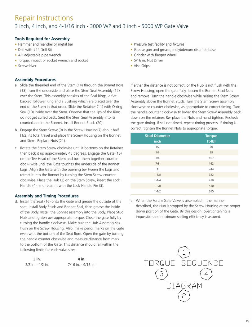
Assembly and Timing Proceduresd. Install the Seat (16) onto the Gate and grease the outside of the
seat. Install Body Studs and Bonnet Seal, then grease the inside of the Body. Install the Bonnet assembly into the Body. Place Stud Nuts and tighten per appropriate torque. Close the gate fully by turning the handle clockwise. Make sure the Hub Assembly sits flush on the Screw Housing. Also, make pencil marks on the Gate even with the bottom of the Seat Bore. Open the gate by turning the handle counter clockwise and measure distance from mark to the bottom of the Gate. This distance should fall within the following limits for each valve size:
3 in. 4 in.
3/8 in. - 1/2 in. 7/16 in. - 9/16 in.
If either the distance is not correct, or the Hub is not flush with the Screw Housing, open the gate fully, loosen the Bonnet Stud Nuts and remove. Turn the handle clockwise while raising the Stem Screw Assembly above the Bonnet Studs. Turn the Stem Screw assembly clockwise or counter clockwise, as appropriate to correct timing. Turn the handle counter clockwise to lower the Stem Screw Assembly back down on the retainer. Re- place the Nuts and hand tighten. Recheck the gate timing. If still not timed, repeat timing process. If timing is correct, tighten the Bonnet Nuts to appropriate torque.
Stud Diameter Torque
inch ft-lbf1/2 60
5/8 89
3/4 107
7/8 162
1 244
1-1/8 322
1-1/4 410
1-3/8 510
1-1/2 615
e. When the Forum Gate Valve is assembled in the manner described, the Hub is stopped by the Screw Housing at the proper down position of the Gate. By this design, overtightening is impossible and maximum sealing efficiency is assured.
Tools Required for Assembly• Hammer and mandrel or metal bar• Drill with #44 Drill Bit• API adjustable pipe wrench • Torque, impact or socket wrench and socket• Screwdriver
• Pressure test facility and fixtures• Grease gun and grease, molybdenum disulfide base• Grinder with flapper wheel• 5/16 in. Nut Driver• Vise Grips
16
Repair Instructions4 inch, 4-1/16 inch, 5 X 4 inch, and 6 X 4 inch - 5000 WP Gate Valve
Assembly Proceduresa. Slide the threaded end of the Stem (9) through the Bonnet Bore
(16), from the underside and draw the Stem Head part way up into the Bonnet. Put the Down Stop Ring (14) over the bottom of the Stem Head. Lower the Stem so that the Down Stop Ring shoulders on the inside of the Bonnet and slide the Gate (19) onto the Tee-Head of the Stem.
b. Place the Stem Seal Assembly (12) over the Stem. This assembly consists of three [3] Seal Rings, a flat backed follower ring and a Bushing which are placed over the end of the Stem in that order. Carefully work down the Seal and follower over the Stem threads. Observe that the lips of the ring do not get curled back. After the Bushing, place the Retainer (11) with O-ring Seal (10) down over the Stem with flat side up.
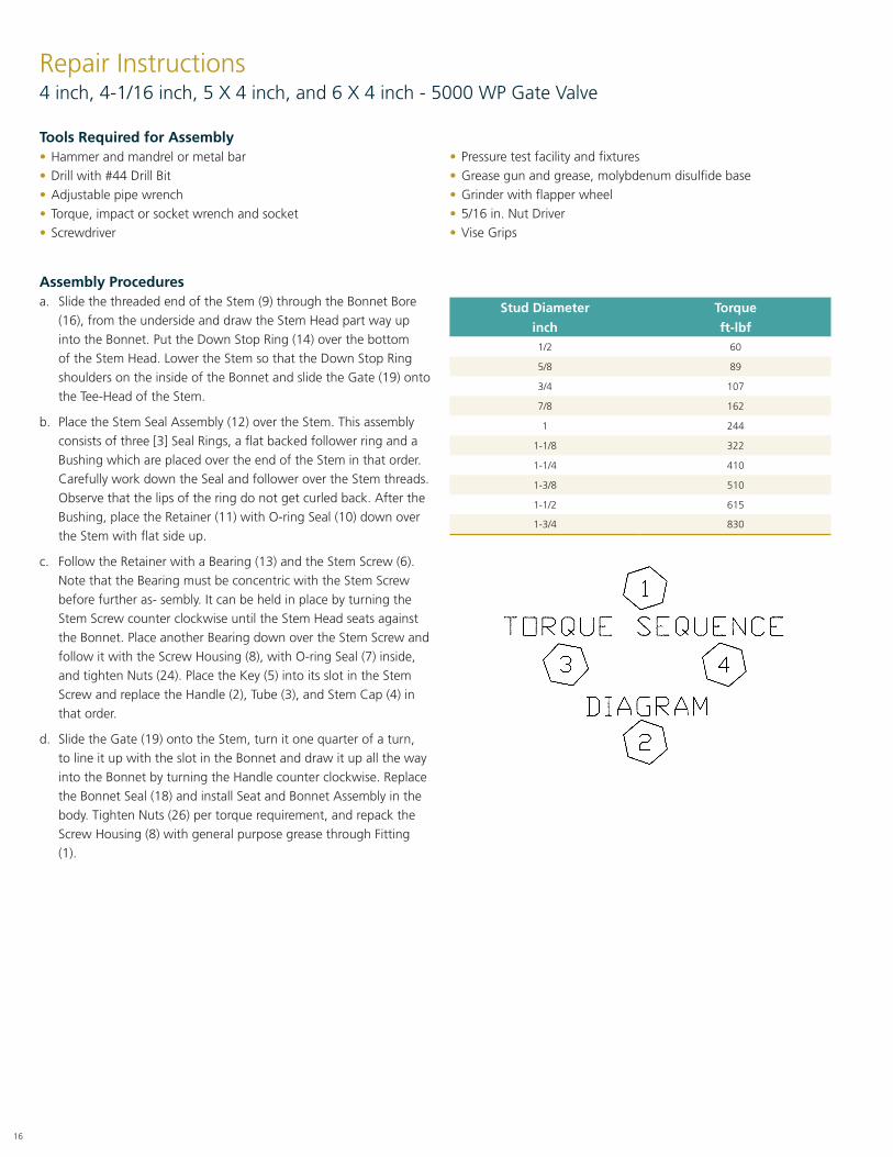
c. Follow the Retainer with a Bearing (13) and the Stem Screw (6). Note that the Bearing must be concentric with the Stem Screw before further as- sembly. It can be held in place by turning the Stem Screw counter clockwise until the Stem Head seats against the Bonnet. Place another Bearing down over the Stem Screw and follow it with the Screw Housing (8), with O-ring Seal (7) inside, and tighten Nuts (24). Place the Key (5) into its slot in the Stem Screw and replace the Handle (2), Tube (3), and Stem Cap (4) in that order.
d. Slide the Gate (19) onto the Stem, turn it one quarter of a turn, to line it up with the slot in the Bonnet and draw it up all the way into the Bonnet by turning the Handle counter clockwise. Replace the Bonnet Seal (18) and install Seat and Bonnet Assembly in the body. Tighten Nuts (26) per torque requirement, and repack the Screw Housing (8) with general purpose grease through Fitting (1).
Stud Diameter Torque
inch ft-lbf1/2 60
5/8 89
3/4 107
7/8 162
1 244
1-1/8 322
1-1/4 410
1-3/8 510
1-1/2 615
1-3/4 830
Tools Required for Assembly• Hammer and mandrel or metal bar• Drill with #44 Drill Bit• Adjustable pipe wrench• Torque, impact or socket wrench and socket• Screwdriver
• Pressure test facility and fixtures• Grease gun and grease, molybdenum disulfide base• Grinder with flapper wheel• 5/16 in. Nut Driver• Vise Grips
17
Assembly Proceduresa. Slide the threaded end of the Stem (14) through the Bonnet Bore
from the underside and place the Stem Seal Assembly (12) over the Stem. This as- sembly consists of the Seal Rings, a flat-backed fol- lower Ring, and a Bushing which are placed over the end of the Stem in that order. Slide the Retainer (11) with O-ring Seal (10) inside of the Stem. Ob- serve that the lips of the ring do not get curled back. Set the Stem Seal Assembly into its counterbore in the Bonnet. Install Bonnet Studs (20).
b. Engage the Stem Screw (9) in the Screw Housing (7) about half (1/2) its total travel and place the Screw Housing on the Bonnet and Stem. Replace Nuts (21).
c. Rotate the Stem Screw clockwise until it bottoms on the Retainer, then back it up approximately 45 de- grees. Engage the Gate (15) on the Tee-Head of the Stem and turn them together counter clockwise until the Gate touches the underside of the Bonnet Lugs. Align the Gate with the opening between the Lugs and retract it into the Bonnet by turning the Stem Screw counter clockwise. Place the Hub (2) on the Stem Screw, insert the Lock Handle (4), and retain it with the Lock Handle Pin (3).
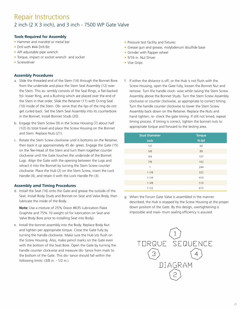
Assembly amd Timing Proceduresd. Install the Seat (16) onto the Gate and grease the outside of the
Seat. Install Body Studs and Bonnet on Seat and Valve Body, then lubricate the inside of the Body.
Note: Use a mixture of 25% Dixon #635 Lubrication Flake Graphite and 75% 10 weight oil for lubrication on Seat and Valve Body Bore prior to installing Seat into Body).
e. Install the bonnet assembly into the Body. Replace Body Nut and tighten per appropriate torque. Close the Gate fully by turning the handle clockwise. Make sure the Hub sits flush on the Screw Housing. Also, make pencil marks on the Gate even with the bottom of the Seat Bore. Open the Gate by turning the handle counter clockwise and measure dis- tance from mark to the bottom of the Gate. This dis- tance should fall within the following limits: (3/8 in. - 1/2 in.)
Repair Instructions2 inch (2 X 3 inch), and 3 inch - 7500 WP Gate Valve
f. If either the distance is off, or the Hub is not flush with the Screw Housing, open the Gate fully, loosen the Bonnet Nut and remove. Turn the handle clock- wise while raising the Stem Screw Assembly above the Bonnet Studs. Turn the Stem Screw Assembly clockwise or counter clockwise, as appropriate to correct timing. Turn the handle counter clockwise to lower the Stem Screw Assembly back down on the Retainer. Replace the Nuts and hand tighten, re- check the gate timing. If still not timed, repeat timing process. If timing is correct, tighten the bonnet nuts to appropriate torque and forward to the testing area.
Stud Diameter Torque
inch ft-lbf
1/2 60
5/8 89
3/4 107
7/8 162
1 244
1-1/8 322
1-1/4 410
1-3/8 510
1-1/2 615
g. When the Forum Gate Valve is assembled in the manner described, the Hub is stopped by the Screw Housing at the proper down position of the Gate. By this design, overtightening is impossible and maxi- mum sealing efficiency is assured.
Tools Required for Assembly• Hammer and mandrel or metal bar• Drill with #44 Drill Bit• API adjustable pipe wrench• Torque, impact or socket wrench and socket• Screwdriver
• Pressure test facility and fixtures• Grease gun and grease, molybdenum disulfide base• Grinder with flapper wheel• 5/16 in. Nut Driver• Vise Grips

18
Assembly Proceduresa. Slide the threaded end of the Stem (9) through the Bonnet (16)
bore, from the underside of the Bonnet, until the Tee Slot on the Stem is half way into the Bonnet Cavity.
b. Slide the Down Stop Ring (14) over the Tee Slot of the Stem and then lower the Stem until the Down Stop Ring shoulders on the Bonnet.
c. Slide the Gate (19) onto the Tee Slot of the Stem, align with Bonnet slot and raise the Stem/Gate as- sembly into the Bonnet until it tops-out.
d. Place Stem Seal Assembly (12) over the threaded part of the Stem. The assembly consists of three [3] Seal Rings, a flat-backed follower ring and a bush- ing.
Note: Carefully work the seals over the Stem threads making sure the seals do not tear or curl.
e. After the bushing, place Secondary (O-ring) Seal (10) into the Retainer (11) and slide onto the Stem so that it rests on the bushing.
f. Place a Bearing (13) on top of the retainer.
g. Thread Stem Screw (6) onto the Stem until the Stem Screw bottoms-out on the bearing and the Gate is completely topped-out in the Bonnet cavity.
h. Place another bearing (13) over the Stem Screw.
i. Place Stem Screw (O-ring) Seal (7) into the Screw Housing (8). Put Screw Housing over the Stem Screw aligning on the Bonnet Studs (23).
j. Tighten Bonnet Stud Nuts (24) on the Bonnet Studs to hold the Screw Housing in place.
k. Place Key (5) into its slot in Stem Screw, put on the Handle Assembly (2), Sight Tube (3), and Stem Cap (4) in that order.
l. Lower the Gate, by turning handle clockwise, until the Stem threads show about one inch in the Sight Tube.
m. Place Bonnet Seal (18) into Body (20) Groove, and thread the Body Studs (25) into Body.
n. Liberally lubricate Gate. Spread the Seat (21) apart using the pegs and put the Seat onto the Gate.
Repair Instructions4 inch and 5 X 4 inch - 7500 WP Gate Valve
o. Slide the Seat onto the Gate until the pegs locate into the Bonnet holes.
p. Lubricate the outside of the Seat and the inside of the Body with mixture of 25% Dixon #635 Lubricat- ing Flake Graphite and 75% 10 Weight Oil.
q. Slide the Seat/Bonnet Assembly into the Body about one to two inches. Raise the Gate until about one inch is still in the Seat.
r. Slide the Seat completely into the Body. Make sure that the Seat is going in straight, otherwise the Seat will tear.
s. Tighten the Body Stud Nuts (26) to the required torque.
t. Lube the Stem with general purpose grease via the Lube Fitting (1).
Note: Refer to pages 28 and 29 for numbered illustration.
Stud Diameter Torque
inch ft-lbf
1/2 60
5/8 89
3/4 107
7/8 162
1 244
1-1/8 322
1-1/4 410
1-3/8 510
1-1/2 615
1-3/4 830
Tools Required for Assembly• Hammer and mandrel or metal bar• Drill with #44 Drill Bit• Adjustable pipe wrench• Torque, impact or socket wrench and socket• Grease gun and grease, molybdenum disulfide base
• Grinder with flapper wheel• Pressure test facility and fixtures• 5/16 in. Nut Driver• Vise Grips• Screwdriver

19
Repair Instructions5-1/8 IN., AND 6 X 5-1/8 IN. - 7500 WP GATE VALVE
Assembly Proceduresa. Slide the threaded end of the Stem (7) through the bore of the
Bonnet (9), opposite the stem seal bore.
b. Place the Stem Seal Assembly (10-14) over the Stem (7) and install into the stem seal bore (gland) in the Bonnet (9). Install in the following order, with the chevron side of the seals facing into the stem seal bore:
• Bottom Adapter (10)• Pressure Ring (11)• Seal Ring (12)• Pressure Ring (11)• Top Adapter (13)• Gland Ring (14)
c. Install the O-ring (15) into the Packing Retainer (18) by applying grease to the O-ring groove. Install the Packing Retainer (18) over the Stem (7) and onto the Bonnet (9). Install four [4] Socket Head Cap Screws (22) and fully tighten.
d. Grease two [2] Needle Bearings (20). Place one [1] Thrust Washer (19) onto the Packing Retainer (18) followed by one [1] Needle Bearing (20) and one [1] Thrust Washer (19).
e. Place the Stem Screw Housing (21) onto the Thrust Washers (19) and Needle Bearing (20). Insert one [1] Thrust Washer (19) onto the Stem Screw Housing (21) followed by one [1] Needle Bearing (20) and one [1] Thrust Washer (19).
f. Install O-ring (23) onto the Stem Screw Housing (21). Install the Bonnet Cap (25) onto the Stem Screw Housing (21). Install four [4] Bonnet Hex Head Cap Screws (26) through the Bonnet Cap (25), Packing Retainer (18), and into the Bonnet (9). Fully tighten the Bonnet Hex Head Cap Screws (26).
g. Install the Handwheel (29) onto the Stem Screw Housing (21). Install O-ring (28) onto the Handwheel Locking Screw (27). Install the Handwheel Locking Screw (27) through the Handwheel (29) and into the Stem Screw Housing (21) and fully tighten.
h. Install the Clear Acrylic Tube (30) over the stem threads. Install the Stem Cap (31) onto the Stem Screw Housing (21) and fully tighten.
i. Install the Gate Clip (6) onto the Stem (7). Install the Gate (5) onto the Stem (7) and bend the tabs of the Gate Clip (6) down and towards the Gate (5).
j. Retract the Stem (7) until it bottoms on the Bonnet (9). Install O-ring (8) onto the Bonnet (9).
k. Install O-ring (4) onto the Wear Ring (3). Repeat for the second O-ring and wear ring. Install two [2] Wear Rings (3) into the Body (1). Install the Seat (2) into the Wear Rings (3) by collapsing the top of the Seat (2), aligning the boss on the Seat (2) with the bore in the Body (1). Release the Seat (2) and the Seat (2) will lock into place.
l. Lightly grease the Body Studs (16) and install the Body Studs (16) into the Body (1). Install the bonnet assembly onto the Body (1). Install the Body Stud Nuts (17) onto the Body Studs (16) and torque to 688 ft-lbs. Torque evenly in a criss-cross fashion.
m. Install the Lube Fittings (24). Apply grease to both fittings.
Tools Required for Assembly• Impact wrench/torque wrench (capable of 700 ft-lbs)• 5/8 in. Allen Wrench
• Standard shop tools• Grease gun with grease

20

21
Drilling Sales Headquarters
10344 Sam Houston Park Drive, Suite 300Houston, TX 77064USA713.351.7900
Regional Offices
Unit 7, Murcar Industrial EstateDenmore Road, Bridge of DonAberdeen AB23 8JWUK44.1224.707800
Oilfields Supply CenterBuilding B-45Jebel Ali Free ZoneDubaiUAE971.4.883.5266
9503 12th Ave S.W. Edmonton, AB T6X 0C3Canada780.980.0345
No 51 Benoi Road #06-00Singapore 629 908Singapore65.6465.4850

Our goal is to become the leading provider of mission critical oilfield products and related services in terms of customer satisfaction, safety and financial performance.
Our experienced management team and employees are dedicated to solving our customers’ problems. We invest in long term relationships and cooperate on product development with our clients, we consider them our partners.
OUR CORE VALUES
No one gets hurt: The safety of our employees and customers is our first priority coupled with a healthy respect for the environment.
Integrity: In everything we do, in every interaction, both internally and externally, we strive to operate with the utmost integrity and mutual respect.
Customer focused: Our products enhance our customer’s performance and we listen to their needs and work with them to solve their challenges.
Good place to work: We are committed to creating a workplace that fosters innovation, teamwork and pride. Every team member is integral to our success and is treated equally and fairly.
®
10344 Sam Houston Park Drive, suite 300Houston, TX 77064+1 713 351 7900 f-e-t.com/[email protected]
DRL1103.08.2018


