58
Mud Removal
| Date post: | 11-Dec-2015 |
| Category: |
Documents |
| Upload: | dk-kakitahi |
| View: | 10 times |
| Download: | 1 times |

Mud Removal

Copyright © 2001 – 2013, Schlumberger. All rights reserved
Objectives of Primary Cementation
Provide complete isolation of zones
– (Hydraulic Bond)
To support the casing
– (Shear Bond)
Protect casing string
2
Copyright © 2001 – 2013, Schlumberger. All rights reserved
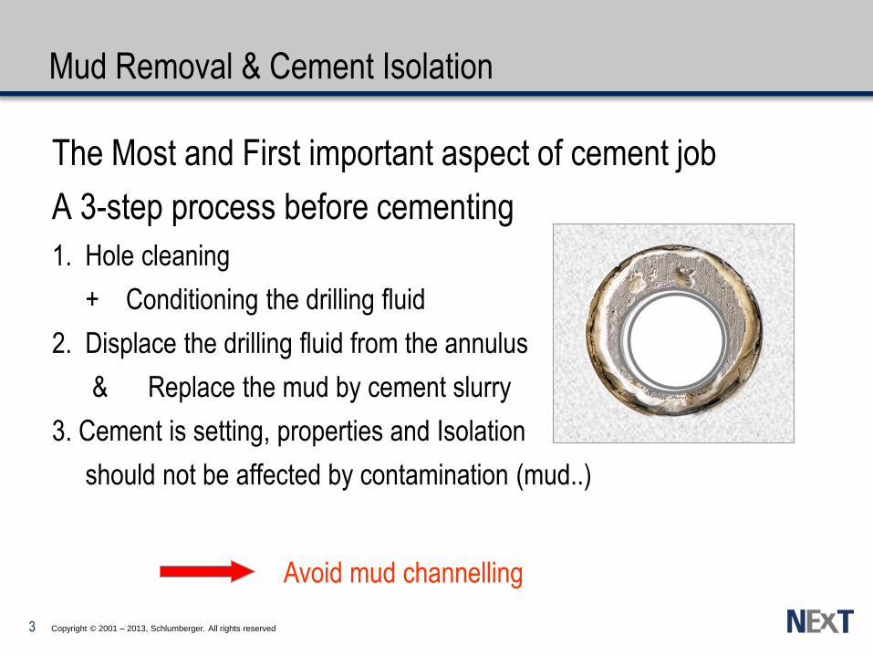
Mud Removal & Cement Isolation
The Most and First important aspect of cement job
A 3-step process before cementing
1. Hole cleaning
+ Conditioning the drilling fluid
2. Displace the drilling fluid from the annulus
& Replace the mud by cement slurry
3. Cement is setting, properties and Isolation
should not be affected by contamination (mud..)
Avoid mud channelling
3
Copyright © 2001 – 2013, Schlumberger. All rights reserved
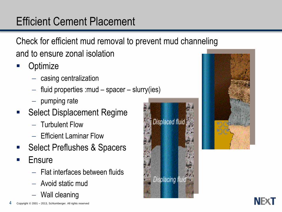
Efficient Cement Placement
Check for efficient mud removal to prevent mud channeling
and to ensure zonal isolation
Optimize
casing centralization
fluid properties :mud – spacer – slurry(ies)
pumping rate
Select Displacement Regime
Turbulent Flow
Efficient Laminar Flow
Select Preflushes & Spacers
Ensure
Flat interfaces between fluids
Avoid static mud
Wall cleaning 4

Bulk mud removal

Copyright © 2001 – 2013, Schlumberger. All rights reserved
The Flow of Fluids
Shear Stress τ
Shear Rate γ =
Apparent Viscosity
r
V1
F A A
A A
V 2
1 Poise = 100 centiPoise = 0.2089 lbf.sec/100ft2 - 1 Pa.s = 2.089 lbf.sec/100ft2
Oilfield units
dv
dr
v v
r
2 1
2100ft
secflb
rateshearstressshear
·
6

Copyright © 2001 – 2013, Schlumberger. All rights reserved
Flow Curves - Fluids Classification
Power Law
NEWTONIAN or NON-NEWTONIAN
Shear rate
LAMINAR FLOW
TURBULENT FLOW
T R A N S I T I O N
T R A N S I T I O N
Z O N E
Z O N E
Shear rate
Shear Stress Bingham
Plastic
Shear
Stress
T R A N S I T I O N
T R A N S I T I O N
Z O N E
Z O N E
Herschel
Bulkley
Power law & Herschel Bulkley fluids :
shear thinning fluids
Drilling and Cementing fluids : HB behaviour (API 13D:2006 – SPE98743) 7

Copyright © 2001 – 2013, Schlumberger. All rights reserved
Flow Models
For mathematical representation, following models are used:
1. Newtonian model t =
2. Bingham plastic model t = ty + p = p + ty /
ty BinghamYield p plastic viscosity
3. Power Law Model t =K = K
(Pseudo plastic model)
K consitency index (lbf.s^n/100ft²)
n flow behaviour index (dimensionless)
4. Herschel Bulkley model t = ty + K
(Pseudo plastic model with a Yield)
g ·
g · g ·
g n · g n-1 ·
g n · g n ·
g · ty + K
=
8
Copyright © 2001 – 2013, Schlumberger. All rights reserved
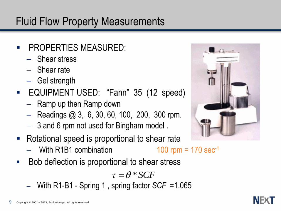
Fluid Flow Property Measurements
PROPERTIES MEASURED:
Shear stress
Shear rate
Gel strength
EQUIPMENT USED: “Fann” 35 (12 speed)
Ramp up then Ramp down
Readings @ 3, 6, 30, 60, 100, 200, 300 rpm.
3 and 6 rpm not used for Bingham model .
Rotational speed is proportional to shear rate
With R1B1 combination 100 rpm = 170 sec-1
Bob deflection is proportional to shear stress
With R1-B1 - Spring 1 , spring factor SCF =1.065
SCF*t
9
Copyright © 2001 – 2013, Schlumberger. All rights reserved
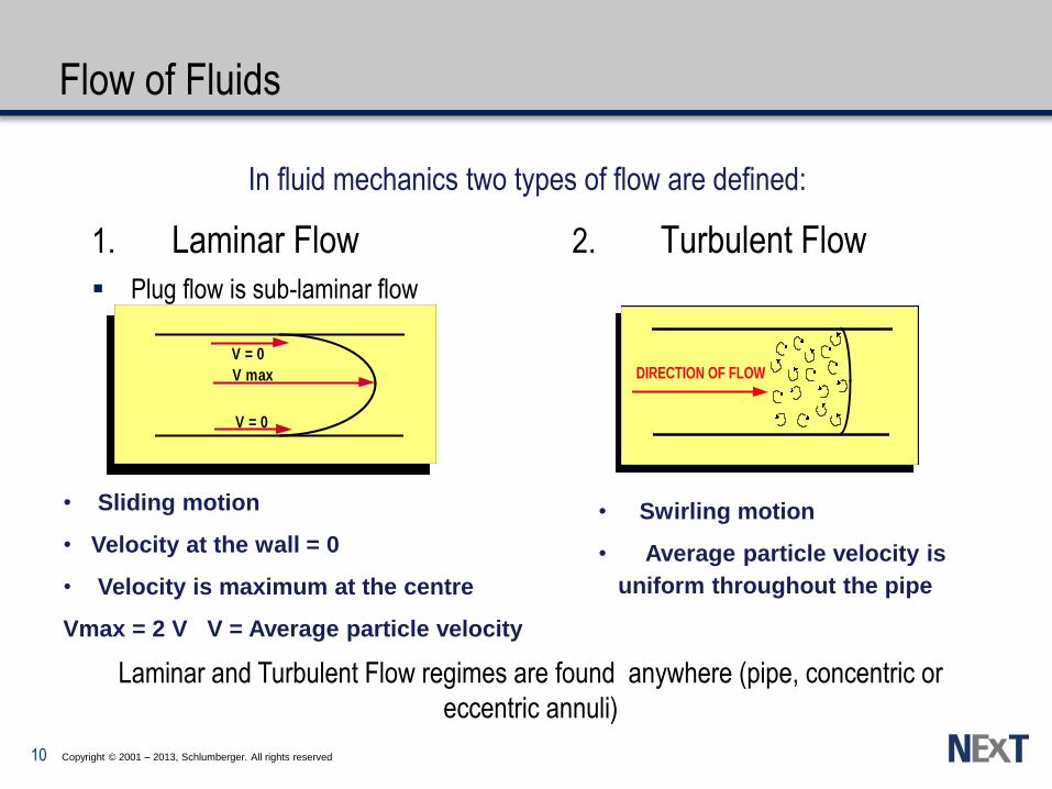
Flow of Fluids
1. Laminar Flow
Plug flow is sub-laminar flow
2. Turbulent Flow
In fluid mechanics two types of flow are defined:
V = 0
V = 0
V max
• Sliding motion
• Velocity at the wall = 0
• Velocity is maximum at the centre
Vmax = 2 V V = Average particle velocity
DIRECTION OF FLOW
• Swirling motion
• Average particle velocity is
uniform throughout the pipe
Laminar and Turbulent Flow regimes are found anywhere (pipe, concentric or
eccentric annuli)
10

Copyright © 2001 – 2013, Schlumberger. All rights reserved
Flow in Eccentric Annuli
Always
Vw > Vn
11
Copyright © 2001 – 2013, Schlumberger. All rights reserved
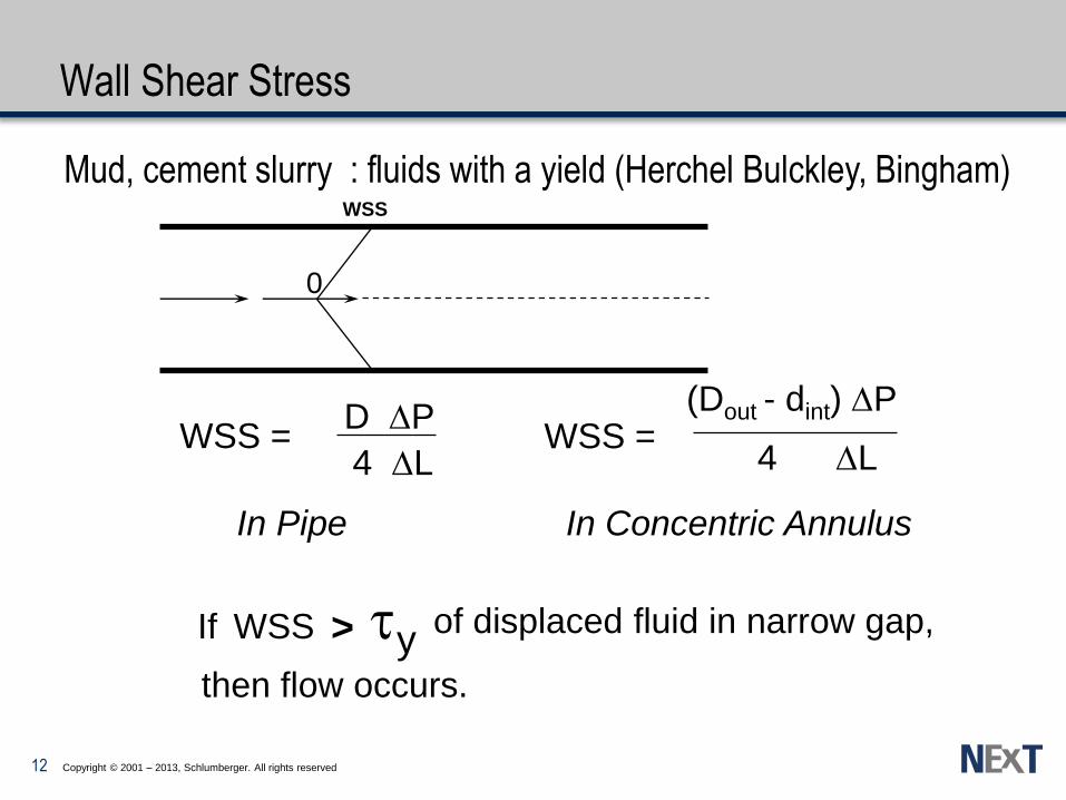
Wall Shear Stress
0
WSS
4 DL
(Dout - dint) DP
WSS = D DP
4 DL WSS =
In Pipe In Concentric Annulus
If WSS > ty of displaced fluid in narrow gap,
then flow occurs.
Mud, cement slurry : fluids with a yield (Herchel Bulckley, Bingham)
12
Copyright © 2001 – 2013, Schlumberger. All rights reserved
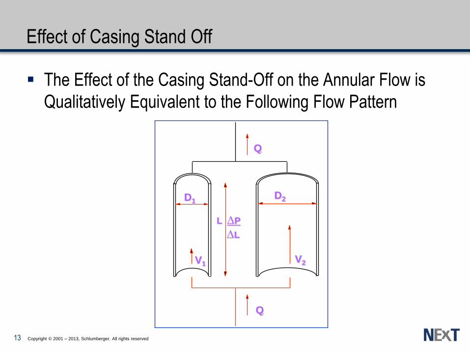
Effect of Casing Stand Off
The Effect of the Casing Stand-Off on the Annular Flow is
Qualitatively Equivalent to the Following Flow Pattern
Q
D1 D2
V2 V1
Q
L DP
DL
13

Copyright © 2001 – 2013, Schlumberger. All rights reserved
Newtonian Fluid of Viscosity µ Density ρ
In LAMINAR FLOW :
Velocity
Reynolds Number
DD
VV
2
1
2
2
1
2
DDIf 2 12
DVDVDV 111122
2
824Re
%67Re8Re 12for
Pipe stand off : 67%
14

Copyright © 2001 – 2013, Schlumberger. All rights reserved
Laminar Flow in Eccentric Annulus
Non-parallel plate model Ri/Ro = 0.8
0 10 20 30 40 50 60 70 80 90 100
1000
500
100
50
10
5
1
Vwide /Vnarrow
Stand-off %
n = 1.0
n = 0.5
n = 0.2
W
% Stand-off = w
RH - RC X 100
RC
RH
15

Copyright © 2001 – 2013, Schlumberger. All rights reserved
Newtonian Fluid of Viscosity µ Density ρ
In TURBULENT FLOW Velocity
Reynolds Number
714,0
1
2
1
2
DD
VV
DDIf 2 12
V2 =1 .64 V1 for 67% stand off
DVDVDV 111122
2
28,3264,1Re
Re 2 = 3.28 Re 1 for 67% Stand off
16

Copyright © 2001 – 2013, Schlumberger. All rights reserved
Turbulent Flow in Eccentric Annulus
0 10 20 30 40 50 60 70 80 90 100
1000
500
100
50
10
5
1
Vwide / Vnarrow
API Stand - Off (%)
n = 1.0
n = 0.5
n = 0.2
W
% Stand-off = w
RH - RC X 100
RC
RH
17
Copyright © 2001 – 2013, Schlumberger. All rights reserved
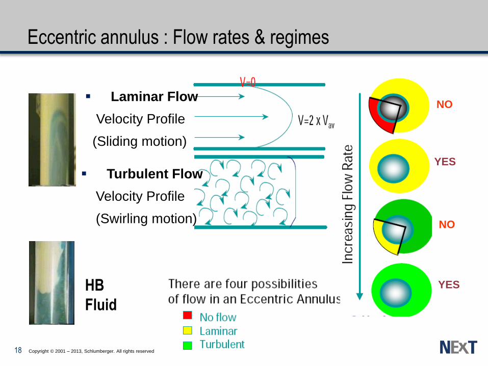
Eccentric annulus : Flow rates & regimes
Laminar Flow
Velocity Profile
(Sliding motion)
Turbulent Flow
Velocity Profile
(Swirling motion)
NO
NO
YES
YES
HB
Fluid
18
Copyright © 2001 – 2013, Schlumberger. All rights reserved
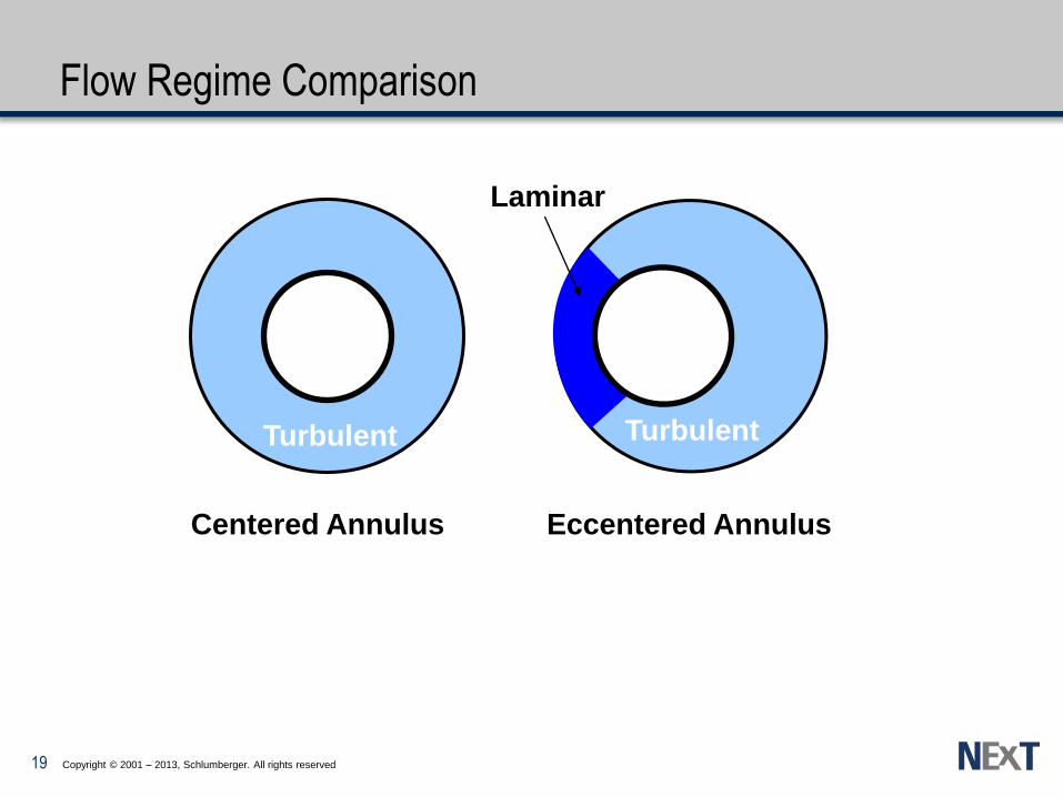
Flow Regime Comparison
Turbulent
Centered Annulus
Laminar
Eccentered Annulus
Turbulent
19

Copyright © 2001 – 2013, Schlumberger. All rights reserved
Turbulent Flow Reynold’s number correction
RH
RC
W
% STO = X 100 RH - RC
W
Correction factor to apply to centered annulus NRe
to provide turbulence in the narrow side
20

Copyright © 2001 – 2013, Schlumberger. All rights reserved
Turbulent Flow Guidelines
The best flow regime for displacement :
Cementing fluids in turbulent flow all around eccentered pipe
Function of standoff, annular flow rate, hole size
Contact time 10 min across zones of interest – Minimum contact time of 6 minutes – Must take u-tubing into account – Maximize by increased volume or decreased rate
For chemical wash Allows for contamination – consider a viscosity of 5 cp
BUT ! Due to differential density, interfaces are not stable in annulus :
Preflushes (Spacer/wash) density should be close and higher than mud density
turbulent flow ρ(2) displacing ρ(1) mud
21
Copyright © 2001 – 2013, Schlumberger. All rights reserved
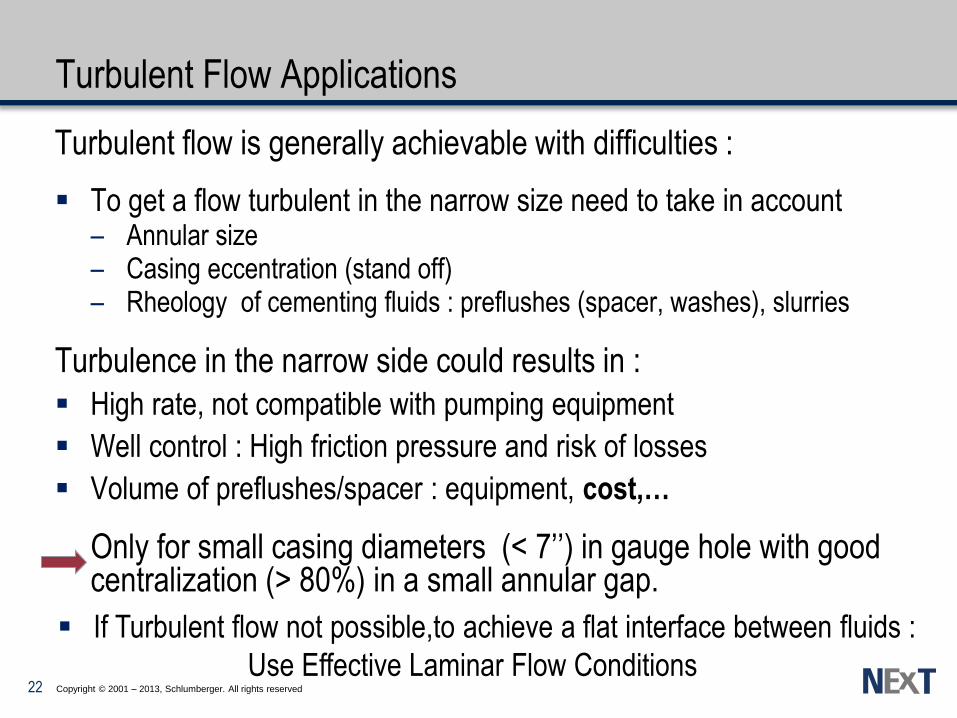
Turbulent Flow Applications
Turbulent flow is generally achievable with difficulties :
To get a flow turbulent in the narrow size need to take in account – Annular size – Casing eccentration (stand off) – Rheology of cementing fluids : preflushes (spacer, washes), slurries
Turbulence in the narrow side could results in :
High rate, not compatible with pumping equipment
Well control : High friction pressure and risk of losses
Volume of preflushes/spacer : equipment, cost,…
Only for small casing diameters (< 7’’) in gauge hole with good centralization (> 80%) in a small annular gap.
If Turbulent flow not possible,to achieve a flat interface between fluids :
Use Effective Laminar Flow Conditions 22

Copyright © 2001 – 2013, Schlumberger. All rights reserved
Efficient Laminar Flow
Alternative flow to provide a flat displacement front
Four (+ 1) rules must be satisfied:
– Density differential
– Friction pressure hierarchy
– Minimum pressure gradient
• Mud in motion
• No Mud on the Wall
– Differential velocity criterion
– Turbulence to be avoided
23
Copyright © 2001 – 2013, Schlumberger. All rights reserved
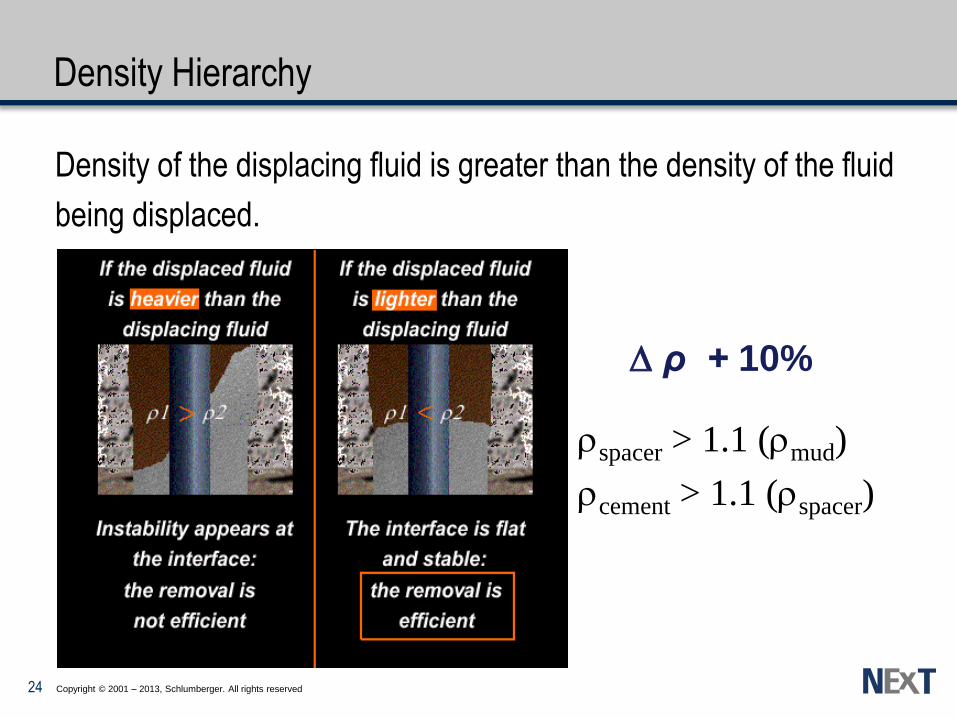
Density Hierarchy
Density of the displacing fluid is greater than the density of the fluid
being displaced.
D ρ + 10%
spacer > 1.1 (mud)
cement > 1.1 (spacer)
24

Copyright © 2001 – 2013, Schlumberger. All rights reserved
Friction Pressure Hierarchy
Promotes a flat stable interface with less possibility of viscous fingering
Friction pressure of displacing fluid must be greater than friction pressure of fluid being displaced.
displacing displaced
> 1.2 DP
DL
DP
DL
D + 20% DL
DP
25

Copyright © 2001 – 2013, Schlumberger. All rights reserved
Minimum Pressure Gradient
To get a flow of the fluid (mud) all around the eccentric annulus
Wall Shear Stress must exceed the yield stress of the fluid on the narrow side:
Function of standoff
Applies only to fluids with a yield point
Translates into a lower limit for flow rate
Approximated from:
Q mini = Mud circulation rate above MPG
STO (DOH-Dc)
4ty
>
No Flow
Laminar Flow
WSS > ty
DP
DL
26

Copyright © 2001 – 2013, Schlumberger. All rights reserved
MPG and Mud On the Wall
To displace Mud by Spacer and Spacer by Slurry:
Avoid Stable layer of mud (or Spacer) left on casing and formation
Wall shear stress (WSS spacer)
if WSS Spacer>ty,mud => no mud film
if WSS spacer <ty,mud =>Mud On the Wall
- Looks” like a channel
– But thicker on the formation
– Dehydration at the formation face
L
x
0
v t
tMax
(WSS)
Minimum Pressure Gradient for the mud Mud in motion (eccentered annulus size E) if
WSS mud = (1/4) (E) > Gel mud
DP
DL E
27
Copyright © 2001 – 2013, Schlumberger. All rights reserved
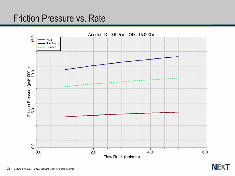
Friction Pressure vs. Rate
0.0 2.0 4.0 6.0Flow Rate (bbl/min)
15.0
10.0
5.0
0.0
Frictio
n P
ressure
(psi/1
000ft)
Mud
Tail Slurry
Spacer
Annulus ID : 9.625 in - OD : 15.000 in
29

Copyright © 2001 – 2013, Schlumberger. All rights reserved
Calculating Annular Shear Rate
g (2471) Q
(Do - Di)2 (Do + Di)
where:
g Annular Shear Rate
Q = Rate (BPM)
Do = Outer Diameter (in.)
Di = Inner Diameter (in.)
Fann 35 Speed
(RPM)
Shear Rate
(sec-1
)
300 511
200 340
100 170
60 102
30 51
6 10
3 5
.
.
In concentric annulus
Annular shear rate should be compared to Fann measurements
30
Copyright © 2001 – 2013, Schlumberger. All rights reserved
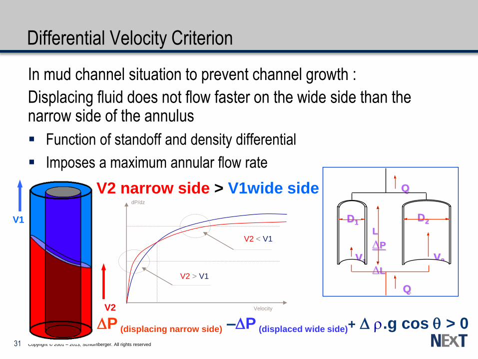
Differential Velocity Criterion
In mud channel situation to prevent channel growth :
Displacing fluid does not flow faster on the wide side than the narrow side of the annulus
Function of standoff and density differential
Imposes a maximum annular flow rate
V2 narrow side > V1wide side Q
D1 D2
V2 V1
Q
L
DP
DL
Velocity
dP/dz
V2 > V1
V2 < V1
DP (displacing narrow side) –DP (displaced wide side)+ D .g cos > 0
V1
V2
31

Copyright © 2001 – 2013, Schlumberger. All rights reserved
Fluids will naturally climb faster on the wide (upper) side
Density drives displacing fluid to the narrow side
– Density hierarchy and differential velocity
– For non-newtonian fluids additional viscosity effects
Horizontal wells
– Axial vs. azimuthal
– Dynamic vs. static channeling
Differential velocity vs. MPG
– Static channel depends on ty
Channeling
c > s s
MPG
Diff Vel.
Mud
On the Wall 32

Copyright © 2001 – 2013, Schlumberger. All rights reserved
Effective Laminar Flow
Minimum Annular Rate
MPG Exceeded
Beginning of 20% Pfriction
Arbitrary limit of 1 BPM
Beginning of stable front
Maximum Annular Rate
Turbulence of displacing
End of 20% Pfriction
Arbitrary limit of 40 BPM
End of stable front
Assume deviation even in “vertical” wells
0.02 to 0.04°/100 ft vertical deviation
0.05°/100 ft azimuthal bearing change
33
Copyright © 2001 – 2013, Schlumberger. All rights reserved
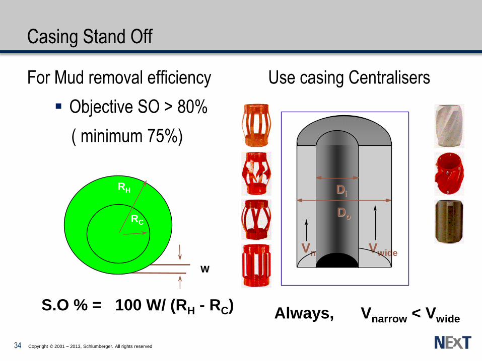
Casing Stand Off
For Mud removal efficiency Use casing Centralisers
Objective SO > 80%
( minimum 75%)
Vnar Vwide
Always, Vnarrow < Vwide
Di
Do
w RH - RC
% Stand-off = X 100
W
RC
RH
S.O % = 100 W/ (RH - RC)
34

Copyright © 2001 – 2013, Schlumberger. All rights reserved
Flow improvement in eccentric annulus
Casing movement : Reciprocation & Rotation ?
35

Copyright © 2001 – 2013, Schlumberger. All rights reserved
Reciprocation
Movement of casing up and down during the job
Must be done from the start of circulation to end displacement
20 to 40 feet stroke
Needs scratchers
(cable type) to be effective
Possible excessive
swab and surge pressures
Excessive pull and buckling
Casing may become stuck
during movement
Cannot be the only method
of mud removal
Sta
tic
Mu
d
Slu
rry
Poor
Stand Off
Slu
rry
Slu
rry
Improved
Stand Off
1 to 5 minutes per cycle
36

Copyright © 2001 – 2013, Schlumberger. All rights reserved
Rotation
Circular movement of pipe
Must be done from the start of circulation to end displacement
10 to 30 rpm
Scratchers help efficiency
Needs special rotary
cement heads and power swivels
Torque must be very closely
monitored
Cannot be the only method
of mud removal
More effective than reciprocation
Mud
Almost
Removed
Rotation
Started
Casing
Stationary
Flowing
Cement
Gelled Mud
37

Spacers & Washes Cementing Plugs
38

Copyright © 2001 – 2013, Schlumberger. All rights reserved
Contamination : Fluids Incompatibility
Results In:
Detrimental Interface Reactions
High Rheological Properties
– Very high viscosities and high gel strengths
Change in Cement Slurry Properties
– Thickening time altered
– Increase in fluid loss
– Reduction in compressive strength
Reduction in Hydraulic Bond
Prevented By
Wiper Plugs in Casing
Compatible Preflushes in Annulus – Spacers and Chemical Washes
39

Copyright © 2001 – 2013, Schlumberger. All rights reserved
Cement placement: Down the casing
Down : Inside the casing :
Fluid interfaces are unstable (mud < spacer < cement)
Mechanical plugs should be used to separate the fluids
Top plug also designed to give indication of end of job (plugs bump on
landing collar)
Lack of bottom plug(s) will lead possibly to
– Fluid contamination (intermixing) or even fluid swapping
– Improper displacement in the annulus
– Poor cement at shoe (top plug scrapping mud film at casing wall)
40
Copyright © 2001 – 2013, Schlumberger. All rights reserved
Cement Wiper Plugs
Keep Fluids Separated in Casing and Reduce Contamination
Bottom Plug(s)
– Remove mud ahead of cement
– Prevent cement falling through lighter fluid ahead
– Wipe inner casing walls clean
– Use at least 1 ..or more if possible
• Long cemented interval
• Critical operation
Top Plug
– Separate cement from displacing fluid
– Positive indication of end of displacement
41
Copyright © 2001 – 2013, Schlumberger. All rights reserved
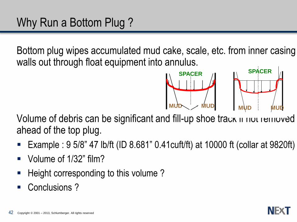
Why Run a Bottom Plug ?
Bottom plug wipes accumulated mud cake, scale, etc. from inner casing walls out through float equipment into annulus.
Volume of debris can be significant and fill-up shoe track if not removed ahead of the top plug.
Example : 9 5/8” 47 lb/ft (ID 8.681” 0.41cuft/ft) at 10000 ft (collar at 9820ft)
Volume of 1/32” film?
Height corresponding to this volume ?
Conclusions ?
SPACER
MUD MUD MUD MUD
SPACER
42

Copyright © 2001 – 2013, Schlumberger. All rights reserved
Why Run a Bottom Plug ?
Volume of residual mud scrapped by the top plug :
Π x ID x L x e
3.14 x (8.681 /12) x 9820 x (1/32 x 1/12) = 58.1 cuft
Length of 9 5/8 casing filled by scrapped mud
58.1 / 0.41 = 141.7 ft
Shoe track length : 180 ft
If an overdisplacement is occuring potential displacement of mud around
the 9 5/8 shoe
43

Copyright © 2001 – 2013, Schlumberger. All rights reserved
Cement placement: Up the annulus
Up : inside annulus
Fluid interfaces can be stable (mud < spacer < cement)
but casing has to be properly centralized.
Fluids density, rheology and pumping rate to be designed properly
depending on the flow regime (laminar vs. turbulent).
Improper displacement (design or execution) in the annulus will lead to :
– Mud/spacer channels in the annulus
– Mud/spacer films at the casing/formation walls
– Fluid contamination (intermixing)
44

Copyright © 2001 – 2013, Schlumberger. All rights reserved
Up the annulus to separate mud from cement :
USE SPACERS in order to prevent contact and incompatibilities
between drilling mud and cement slurries
Some mud additives are retarders for cement
– e.g. lignosulfonate (dispersants)
Others act as accelerators
– CaCl2
Drilling mud/cement mixtures can be very viscous (NABM):
– Absolutely avoided
– Higher friction pressures than expected
• possibly overcoming frac pressure
– Mixtures possibly very difficult to displace from the annulus (gelation)
Improve cement bonding by water wetting casing and borehole (NABM)
45

Copyright © 2001 – 2013, Schlumberger. All rights reserved
Spacers & Washes - Definitions
Compatible:
Capable of forming a mixture which does not undergo any undesirable chemical or physical reactions
Wettability:
The preferential adhesion of polar fluids, such as water, versus non-polar fluids, such as oils, to solid surfaces
46
Copyright © 2001 – 2013, Schlumberger. All rights reserved
Washes & Spacers
Spacers
Densified polymer fluids with insoluble weighting agent (generally barite)
Designed rheology for efficient laminar or turbulent flow displacement Fluid loss control should be required Contains always a surfactant when used with NABM
– compatibility,water wet surface.
Chemical Washes or Preflushes
Generally not densified (Brine) : water, diesel, or thin fresh mud CW contains additives to thin the mud, to control leak off as water wetting
surfactant (NABM) CW pumped in turbulent flow but are not really effective in annulus
– casing eccentration, Taylor instabilities
47

Copyright © 2001 – 2013, Schlumberger. All rights reserved
NABM - Spacer Surfactants Efficiency
48
Copyright © 2001 – 2013, Schlumberger. All rights reserved
Required Properties of Spacers
Compatible with all other well fluids
Stability (good suspending capacity)
Controllable density and rheology
Good fluid loss control
Environmentally safe and easy to handle in the field
Water Wet surface with NABM
50
Copyright © 2001 – 2013, Schlumberger. All rights reserved
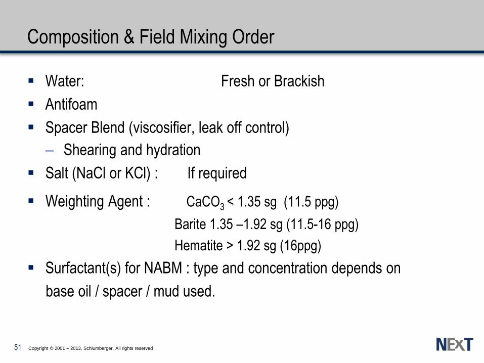
Composition & Field Mixing Order
Water: Fresh or Brackish
Antifoam
Spacer Blend (viscosifier, leak off control)
Shearing and hydration
Salt (NaCl or KCl) : If required
Weighting Agent : CaCO3 < 1.35 sg (11.5 ppg)
Barite 1.35 –1.92 sg (11.5-16 ppg)
Hematite > 1.92 sg (16ppg)
Surfactant(s) for NABM : type and concentration depends on
base oil / spacer / mud used.
51

Copyright © 2001 – 2013, Schlumberger. All rights reserved
Cement placement : Turbulent or Laminar Flow
In all cases Prevent Cement contamination by using/pumping
Along casing down to shoe :
– Separation plugs : Bottom & Top Plugs • 2 Bottom plugs if possible
– Chemical wash ahead plug : • Mud dilution and/or turbulence
Up along the annulus : Spacer ( laminar or turbulent)
Chemical wash (brine?) only with
• Compatible mud ( WBM) with slurry
• Low density mud (< 1.20 sg)
A must do for compatibility with Non Aqueous Base Muds : Chemical wash & spacer + surfactant
Weatherford plugs
52

Conclusions & Resume
Mud displacement and removal

Copyright © 2001 – 2013, Schlumberger. All rights reserved
Criteria for Effective Mud Removal
Cementing Operation :
Centralize casing
Casing movement
Wiper plugs
Spacer and Washes
Flow regime selection
With
Conditioned mud in hole
55
Copyright © 2001 – 2013, Schlumberger. All rights reserved
Mud Removal
Hole Cleaning
– Controlled & optimized mud properties
– Low gravity drill solids < 6%
– Break gel strength
• Wiper trip and intermediate circulation RIH casing
– > 95% Total hole volume in circulation (calliper fluid)
• Calliper log
Conditioning Mud
– Lower TY and PV, flat gel
– Clean hole, LGS < 6%
– Maximum flow rate compatible with minimum frac pressure
– Rate above minimum rate to flow all-around pipe (MPG)
56
Copyright © 2001 – 2013, Schlumberger. All rights reserved
Conclusions: Mud displacement
Centralize to give optimum casing stand-off (80% minimum 75%)
Rotate and/or Reciprocate casing
– Rotation is preferred
– Use cable-type scratchers when reciprocating
Always use a bottom plug: 2 preferred….when possible!
Optimise slurry placement using a simulator:
– Turbulent flow preferred, or in combination with
– Effective laminar flow technique
Use Chemical wash pre-flushes ahead bottom plug
Use Spacer to avoid contact mud/cement slurry
Control spacer/cement slurry properties: batch mix when possible
Compatibility test mud/spacer/cement slurry : lab/field test
58
Copyright © 2001 – 2013, Schlumberger. All rights reserved
Effective Laminar Flow displacement (1)
General Flow regime when Turbulent flow is not possible
Four criteria must be satisfied (for spacer and slurries)
Density differential (10%)
Minimum pressure gradient (MPG)
Friction pressure hierarchy (20%)
Differential velocity criterion
Wash : To clean inside casing ( turbulent flow)
Use 3 – 7 m3 (20 - 40 bbls) chemical wash
Turbulent flow inside casing
Ahead of bottom plug
59

Copyright © 2001 – 2013, Schlumberger. All rights reserved
Effective Laminar Flow displacement (2)
Viscous spacer
Conditioned and clean mud
Viscosity adjustable
– Higher than mud
– WSS > ty,mud
Volume to use: > 150 m - 10 m3 ( 500 ft or 60 bbls)
Surfactant with NABM for water wetability and compatibility
Slurry (ies)
Viscosity adjusted and higher than the spacer
Casing Centralization : Stand off > 75%
60
Copyright © 2001 – 2013, Schlumberger. All rights reserved
Turbulent Flow Displacement (1)
Preferred and best flow regime …..When possible
Applicable at least to Spacer when possible ( laminar slurry)
Critical rate depends on:
Fluid rheologies
Casing stand-off : 85% recommended, minimum 80%
Annular gap, casing OD and Open hole size (bit size)
Formation fracture gradient
61
Copyright © 2001 – 2013, Schlumberger. All rights reserved
Turbulent Flow Displacement (2)
Use Turbulent Spacer and/or Chemical Wash
10 min. Contact time (> 6 min) or 300m (use greater volume))
Spacer density to be close to that of mud
Wash applicable only with low density mud (< 1.20 sg -10 ppg)
Turbulent spacer + Wash to clean inside casing ( preserve the spacer for annulus)
Water wet casing and formation with NABM (surfactant)
Optimise cement slurry properties:
Turbulence at the lowest rate : Minimum PV and TY without settling
Fluid loss and Free Fluid controlled
62


