MECSYCO (Multi-agent Environment for Complex SYstems COsimulation) is a software to modeland simulate complex systems. It enables to realize heterogeneous and digital simulations fromexisting simulators.
The main problematic of MECSYCO is the integration of distinct sub-systems. We propose todesign the system as a multi-model and to use a multi-agent paradigm to run it.
The multi-model approach of MECSYCO is applicable on different levels:
• multi-domain level.
• coupling level: how the information are exchanged between the models.
• formalism level: discrete or continuous.
• simulator level : pre-existing softwares.
• programming language level: some tool are only available with a specific language.
• hardware level : some tool needs a particular hardware.
3
Chapter 1
MECSYCO’s features
1.1 MECSYCO’s purpose
MECSYCO manages the decentralized multi-simulation of a multi-model in a paralleland/or distributed way. Let us introduce the different terms of this previous definition:
• Multi-model: A multi-model is a model composed of several models in interaction. Eachmodel may use its own formalism and spatial and temporal scales. [Siebert, 2011]
• Multi-simulation: A multi-simulation consists of simulating a multi-model using a simula-tor for each model
• Decentralized simulation: A multi-simulation executed without global coordinator.
• Parallel simulation: A multi-simulation performed using different processes but with ashared memory [Fishwick, 2007]
• Distributed simulation: A multi-simulation ”performed on loosely connected nodes, suchas a cluster of workstations connected by a local network, or a geographically separated set ofservers connected over a wide area network.” [Fishwick, 2007]
1.2 Modeling hypothesis
In MECSYCO we have made the hypothesis that all the models composing the multi-model arecompliant with the DEVS formalism (see Appendix B for more details on this formalism). Thisformalism has the advantage of being an execution model proved to be compatible with all otherformalisms. The DEVS simulation protocol imposes some assumptions on the model:
• Model’s inputs can NOT immediately (in term of simulation time) generate model’s outputs
• Models have to conform to the primitives of the protocols. This implies the possibility todefine the operations listed in section 2.3.3.
1.3 Simulation strategy
The execution of a multi-simulation must respect the causality constraint, that is to say: eachsimulator must processes events in timestamp order [Fujimoto, 2001]. Two types of ap-proaches exist to fulfill this requirement [Fishwick, 2007]:
• The conservative approaches consists of insuring that the causality is never broken duringthe simulation.
• The optimistic approaches consists of detecting when the causality constraint is brokenand then rolling back the simulation to this point.
The optimistic approaches required all the simulators to have a roll back capability implemented
4
either with a state saving or inverse computation strategy [Fishwick, 2007]. As this requirementstrongly restricts the type of the simulators which can be used, we have made the choice in thecurrent MECSYCO specification, to take a conservative approach. However, the DEVS opti-mistic strategy [Zeigler et al., 2000] may also be implemented in future version of MECSYCO asit is compatible with the concept and hypotheses of MECSYCO.
The MECSYCO conservative simulation algorithm is based on the DEVS version [Zeigler et al.,2000] of the Chandy Misra Bryant algorithm [Chandy and Misra, 1979]. This algorithm is detailedin Appendix C. Conservative approaches have a well-known limitation: every simulator involvedin the decentralized multi-simulation must define a non-null minimum propagation delay inorder to computes its lookahead (for more details on this point see Section 2.3.1 and Appendix C).
Despite being proved to respect the causality constraint, the algorithm may break the causality ifthe minimum propagation delay is wrongly defined. In order to ensure that a multi-simulationrespect the causality constraint, MECSYCO will throw a Causality Exception if the causalityis broken.
1.4 Integrated simulators
This section presents simulators already include in MECSYCO, that is to say that all extensionsand libraries needed for simulate the model are included.
1.4.1 NetLogo
NetLogo is a multi-agent programmable modeling environment used for simulating natural and so-cial phenomena. It is a tool well suited for modeling complex systems developing over time thanksto the agent system that permit the explore the connection between the micro-level behavior andthe macro-level patterns that emerge from their interaction.
It is used by tens of thousands of students, teachers and researchers worldwide. It also pow-ers HubNet participatory simulations. It is authored by Uri Wilensky and developed at the CCL.You can download it free of charge. It also has extensive documentation and tutorials 1.
1.4.2 FMU
Not distributed yet
FMI defines a tool-independent standard for exchanging models and running standalone simu-lation tools 2. A simulation model exported according to the FMI standard is called a FunctionalMockup Unit (FMU). The FMU is like a black box with inputs and outputs port, and explicitinterface to interact. It is an archive file that contains the source or object code needed to executethe model (*.bin), and an XML file describing the capabilities of the model (functions, connectingport, parameters etc...). The FMI standard has two different ways of working, Model Exchange andCo-Simulation (Figure 1.1). The first one is a dynamic component representation using differen-tial, algebraic and discrete equations. For Model Exchange, it is needed that the master algorithmprovide the necessary solvers. In the other hand, Co-Simulation defines an interface for couplingindependent simulation tools. That is to say that the FMU provides the associated solvers. In bothcases, the master algorithm coordinates time and exchanges between FMUs [Blochwitz et al., 2011].
The FMI standard has two version (1.0 and 2.0), but these two versions are not supported byevery modeling tools yet. For now, MECSYCO can use well Co-Simulation models for version 1.0and need more development for the 2.0.
Figure 1.1: FMI for ModelExchange and for Co-Simulation
1.5 Implementation choices
1.5.1 Middleware for distributed simulation
To perform a distributed multi-simulation, MECSYCO currently uses the Data DistributionService (DDS) [OMG, 2007] communication middleware. DDS is an OMG standard for real-time communication and scalable systems. Currently, the DDS implementation used in MECSYCOis Prismtech Opensplice Community Edition 6.33.
At the deployment level, the constraints of DDS are that communications are done using themulticast protocol. This implies that:
• the IP addresses of the connected devices have to be set in the same network (LAN).
• the firewall(s) used inside the network should NOT block multicast messages.
For the communication through DDS, messages are serialized using the open standard formatJSON [ECMA, 2013].
DDS is currently the only available choice, but MECSYCO is not dependent on it and canswitch from a communication middleware to another easily.
MECSYCO is currently implemented in Java and C++ programming languages. In the followingsections, we detail each of these implementations. Note that we care to develop the C++ sourcesas close as possible of the Java sources, for easier maintenance.
Java implementation of MECSYCO
The Java code of MECSYCO supports Java 1.7 version or higher either with the OpenJDK orOracle Java Virtual Machine. The MECSYCO’s features have been tested with this implementationin various OS configurations (see table 1.2). Using Eclipse4 for developing is encouraged.
OS ConfigurationsParallelsimulation
Distributedsimulation(OpenSplice)
HLAConnection
FMIConnection
Windows 8.1 x64 X ? X X
Windows 7x64 X X ? Xx86 X X ? X
Ubuntu 12.04x64 X X ? Xx86 X ? ? ?
GNU/Linux Debian Jessie x64 X X ? X
Mac OS X 10.9.4 x64 X Not supported ? N/A
Mac OS X 10.7.5 x64 X Not supported ? N/A
Table 1.1: Compatibility of the MECSYCO Java features with different OS configurations. Greencheck boxes indicate that the MECSYCO Java feature supports the configuration, whereas orangequestion marks indicate that the configuration has not been tested for a feature yet.
C++ implementation of MECSYCO (not distributed yet)
The C++ sources are compiled with GCC5 for GNU/Linux, and Microsoft Visual Studio 20136 forWindows. In the both case, we use a CMakeFiles system, detecting the current OS and compilingall subprojects through auto generated Makefiles. Using QtCreator7 for developing is encouraged.Both versions use Boost8 libraries, with shared pointers.
OS ConfigurationsParallelsimulation
Distributedsimulation(OpenSplice)
FMIConnection
Windows 8.1 x64 X X ?
GNU/Linux Debian Jessie x64 X X ?
Ubuntu 14.10 x64 X X ?
Table 1.2: Compatibility of the MECSYCO C++ features with different OS configurations. Greencheck boxes indicate that the MECSYCO C++ feature supports the configuration, whereas orangequestion marks indicate that the configuration has not been tested for a feature yet.
In this section we provide you an installation guide and a global view of the structure and compo-nentd of MECSYCO. This User Guide is an introduction for the advance guides provided. You willfind some information about each component of MECSYCO, and a tutorial for a basic launcher ofa multi-model (section 2.4.5)
Level 1
ForTester: Learning the base, in other words, learning how to construct the easiestmulti-model (using only pre-made object), and how to visualize and distribute them.
Documentationneeded
Getting Started 1and 2
User Guide:MECSYCO-visu
User Guide:MECSYCO-com-dds
User Guide: Scholarapplications
DownloadMECSYCO-re, MECSYCO-visu, MECSYCO-com-dds, MECSYCO-world-netlogo,Getting started eclipse/maven proect, Scholar applications. And do not forget all thedependencies.
NoteIf you need help to install libraries (MECSYCO or dependencies), you can find a guidesection 2.2. You can find templates for a simple multi-model launcher at the end too.
Table 2.1: User guide list for begginer.
Level 2
ForAdvanced user: Base acquired. Learning how to improve your launcher and yourmulti-model.
Documentationneeded
All level 1 guides
Check sectionSimulation data (2.4.1)and operation (2.4.3and 2.4.4)
User Guide: Createyour own operations
Download Same as level 1. Add the source for MECSYCO-world-netlogo (see section ??).
NoteThe source can help you to understand what kind of data are used by NetLogo, andthen what kind of operation you will need.
Table 2.2: User guide list for advances.
8
Level 3
ForDevelopper user: Base acquired. Learning how to create your own multi-model fromthe scratch (model, ModelArtifact, SimulData).
Documentationneeded
All Level 1 and2 guides
CheckAppendix B
User Guide:SimulDatamanipulation
User Guide:Multiplexer
User Guide:Model Artifact
Download Same as previous levels. Add all sources.
NoteIn order to fully use MECSYCO, you need to understand MECSYCO but also DEVSand the simulators you want to work with (new or current one). We just provide helpfor the implementation part.
Table 2.3: User guide list for a full use of MECSYCO.
2.1 MECSYCO’s overview
For a multi-simulation, we consider a set of models with input and output ports. During amulti-simulation the simulators of models exchange simulation events consisting of time stampedsimulation data.
The MECSYCO meta-model relies on the Agents and Artifacts paradigm [Ricci et al., 2007].In this perspective, a multi-agent system is described by two kinds of concepts:
• The agents are the autonomous part of the system. In MECSYCO, each simulator of themulti-simulation is associated with an agent named m-agent.
• The artifacts are reactive parts of the environment that can be used by the agent in or-der to achieve their goals. The artifacts propose services to the m-agents allowing them tocommunicate with each other, to coordinate their works or to modify their environment. Atthe implementation level, these services correspond to methods. In MECSYCO, two kindsof artifacts exist: interface artifacts are used by the m-agents to collect and put simula-tion events in their models, and coupling artifacts are used by the m-agent to exchangesimulation events. The coupling artifacts use transformation operations to transformsimulation data between simulators.
In the next sections, we detail how these concepts can be manipulated by the user in order todescribed a multi-model with MECSYCO. For each concept, we detail (if relevant):
• What is its purpose in the MECSYCO meta-model
• How to create it
• What are the methods the user needs to manipulate in order to connect the concept withother ones
• What are the methods the user needs to manipulate in order to operationalize the multi-simulation
• What are the methods the user needs to manipulate in order to debug the multi-simulation
For each method and constructor we detail the corresponding implementation in Java (C++ pro-gramming language is not distributed yet).
9
Figure 2.1: Symbols of the MECSYCO components (a) m-agent, (b) coupling artifact, (c) interfaceartifact.
2.2 MECSYCO’s installation guide
2.2.1 Java implementation
Remember that the Java code of MECSYCO supports Java 1.7 version or higher with OpenJDKor Oracle Java Virtual Machine. As said, we used Eclipse for developing it. In this section weshow how to install MECSYCO’s core in your projects (in the case of Eclipse Luna, but it will bethe same for all version of Eclipse).
First, you need to download it at MECSYCO’s website, ”Download” section1 (MECSYCO-re2.0.0). If you had already used the old version of MECSYCO, you can still launch your projectsthanks to the compatible version of the core (MECSYCO-re-compatible). But we still advice youto update your previous project.
MECSYCO is used as a library for your Eclipse project, so after creating a new project (Fig-ure 2.2), you will be able to import libraries thanks to the properties of the project (Figures 2.3to 2.5).
Note that if you put the jar file in the files of the project before importing it, you can use ”AddJARS” instead of ”Add External JARS”
2.2.2 C++ implementation
For now, the C++ implementation is not distributed yet.
2.2.3 Other libraries
You can notice that in the ”Download” section, there is not only MECSYCO-re-2.0.0.jar (or thecompatible version) but there is more. Each librarie is installed in the same way as MECSYCO-re-2.0.0.jar and offer new functions:
• MECSYCO-visu is used for observing and logging the results
• MECSYCO-com-dds enables the distribution of the co-simulation on several machines
• MECSYCO-world-netlogo contains the set of special type of variables needed for NetLogo
• Getting started is the set of pre-made models and artifact needed for the ”Getting Started”section of the website
• MECSYCO application is a set of pre-made models that allows to test and show examples ofthe features of MECSYCO. It also contains the full version of the models used in ”GettingStarted”.
For more information about those different libraries see chapter Extensions of MECSYCO (4). Youcan also find an ”User Guide” associated to each librairies in the” Documentation” section.
2.2.4 Dependencies
Each one of the libraries have external dependencies. It means that they need other libraries towork. Some are other libraries from MECSYCO, and some need to be downloaded elsewhere.Those dependencies and the different links are given in the download section of the website. Inorder to add them easely in your project, put all the jar in a libs folder in the project. In somecase this manipulation is mandatory.
2.3 MECSYCO’s concepts
2.3.1 The m-agent
An m-agent Ai, manages a model mi and is in charge of interactions of this model with theother ones (symbol in Figure 2.1a). Each agent is autonomous and its behavior corresponds tothe parallel abstract simulator of the model (see Appendix C). At the implementation level, eachm-agent matches a thread.
12
Constructor of the m-agent
An m-agent corresponds to the class EventMAgent. Two parameters are used to create anm-agent:
• aAgentName: the name of the agent. It is used in the console for information or debugging.
• aMinPropagationDelay: the minimum time delay an input needs to propagate throughthe system to the output (see the Appendix C for more details). This parameter is optional,by default it is equals to +∞ (no modification of the stack of the events ). If inaccurate, thisparameter may cause a CausalityException during the multi-simulation.
• aMaxSimTime: the maximum time of the multi-simulation.
EventMAgent constructor in C++ implementationNot distributed yet
Methods for connecting the m-agent with the other concepts
An m-agent can be connected to several output and input coupling artifacts (see section 2.3.2) andone interface artifact (see section 2.3.3) using the following methods:
addInputCouplingArtifactParameters:
• coupling - the input coupling artifact (see section 2.3.2) to be connected with the m-agent
• port - the name of the input port of the model where the m-agent will put the events comingfrom the artifact.
addInputCouplingArtifact method in Java implementationpublic void addInputCouplingArtifact(EventCouplingArtifactReader coupling, String port)
addInputCouplingArtifact method in C++ implementationNot distributed yet
Connects an input coupling artifact to the m-agent.
addOutputCouplingArtifactParameters:
• coupling - the output coupling artifact (see section 2.3.2) to be connected with the m-agent
• port - the name of the model output port where the outgoing events will be send to theartifact.
addOutputCouplingArtifact method in Java implementationpublic void addOutputCouplingArtifact(EventCouplingArtifactWriter coupling, String port)
addOutputCouplingArtifact method in C++ implementationNot distributed yet
Connect an output coupling artifact 2.3.2 to the m-agent.
13
setModelArtifactParameters:
• artifact - the interface artifact (see section 2.3.3) to be connected with the m-agent
setModelArtifact method in Java implementationpublic void setModelArtifact (GenericModelArtifact artifact)
setModelArtifact method in C++ implementationNot distributed yet
Set the model artifact of the m-agent.
M-agent’s methods for simulation
The m-agent is the class used to launch a multi-simulation. For a given m-agent, the followingmethods should be called in that order (if needed):
startModelSoftware
startModelSoftware method in Java implementationpublic void startModelSoftware()
startModelSoftware method in C++ implementationNot distributed yet
Initialize the m-agent’s model by calling the init methods of the m-agent’s interface artifact (seesection 2.3.3).
setModelParametersParameters:
• args - the set of the initial parameters
setModelParameters method in Java implementationpublic void setModelParameters (@Nullable String... args)
setModelParameters method in C++ implementationNot distributed yet
Set the initial parameters of the model by calling the setIntialParameters method of the interfaceartifact (see section 2.3.3).
coInitialize
coInitialize method in Java implementationpublic void coInitialize()
coInitialize method in C++ implementationNot distributed yet
Send initialization data to the others m-agents (see Appendix C for more details on the initializa-tion process).
runDo not use this method directly, use the ”start” method of Thread object
run method in Java implementationpublic void run()
run method in C++ implementationNot distributed yet
Start the simulation of the m-agent’s model. Thanks to start(), the agent will be given a thread.
14
2.3.2 The coupling artifact
Each interaction between any m-agents Ai and Aj is reified by a coupling artifact Cij (symbol
in Figure 2.1b). A coupling artifact Cij has a direction: it is the support of the exchanges of eventsfrom Ai to Aj . It works like a mailbox: the artifact has a buffer of events where the m-agentscan post their external output events and get their external input events. Therefore, a couplingartifact Cij has two roles: for Ai, it is an output coupling artifact, whereas for Aj it is an inputcoupling artifact.
Constructor of the coupling artifacts
A coupling artifact for sending external events corresponds to the class EventCouplingArti-factWriter. For receiving external events, you should use the class EventCouplingArtifac-tReader. These classes are abstract and so cannot be used directly. Depending on the com-munication middleware you choose for the decentralization, you have to use the correspondinginstantiation.
If you want to use DDS as communication middleware, a coupling artifact for sending externalevents corresponds to the class DDSEventCouplingArtifactSender:
DDSEventCouplingArtifactSender constructor in Java implementationpublic DDSEventCouplingArtifactSender(String topic)
DDSEventCouplingArtifactSender constructor in C++ implementationNot distributed yet
With DDS, a coupling artifact for receiving external events corresponds to the class DDSEvent-CouplingArtifactReceiver:
public DDSEventCouplingArtifactReceiver (String aTopic, Type aDataType)
DDSEventCouplingArtifactReceiver constructor in C++ implementationNot distributed yet
The ”topic” arguments is the DDS topic to use. No matter what you choose, but the topic mustbe the same between a couple Sender and Receiver. With the Receiver, you have to add the typeof the expected value from the coupling (derived from SimulData, see section 2.4.1, in the firstconstructor).
The special coupling artifact CentralizedEventCouplingArtifact is also available, for central-ized simulation (with agents in the same launcher). This class is both a Sender and a Receiver anddoes not need any argument or at least a name for information (debugging) purpose:
CentralizedEventCouplingArtifact constructor in Java implementationpublic CentralizedEventCouplingArtifact (String aCouplingId)
public CentralizedEventCouplingArtifact()
CentralizedEventCouplingArtifact constructor in C++ implementationNot distributed yet
Example templates of run configurations using centralized coupling artifacts are available in thesection 2.4.5. For decentralize example, see ”User Guide: MECSYCO-com-dds”.
Connection of the coupling artifact with other concepts
In order to transform data between simulators or put to scale the time, operations (see section2.4.3) can be added to the coupling artifact. These operations are sequentially called by the cou-pling artifact in order to transform data or time. The operations are on the Receiver side, that is
15
to say classes derived from EventCouplingArtifactReader, including DDSEventCouplingArti-factReceiver and CentralizedEventCouplingArtifact.
addEventOperationParameters:
• aOperation - the operation to be added
addEventOperation method in Java implementationpublic void addEventOperation (EventOperation aOperation)
addEventOperation method in C++ implementationNot distributed yet
Add an operation for data to the coupling artifact.
addT imeOperationParameters:
• aOperation - the operation to be added
addTimeOperation method in Java implementationpublic void addTimeOperation (TimeOperation aOperation)
addTimeOperation method in C++ implementationNot distributed yet
Add an operation for time to the coupling artifact.
2.3.3 The interface artifact
The interface artifact Ii reifies interactions between an m-agent Ai and its model mi (symbol inFigure 2.1c). An interface artifact contains primitives to manipulate a simulator. As a consequence,each interface artifact is specific: to a simulator, if the interface is relatively for all models (FMI);to a model otherwise (NetLogo), and must be defined by the user.
Constructor of the interface artifact
Defining an interface artifact consists of creating and instantiating a class implementing the in-terface GenericModelArtifact. The designer is free to add attributes and other methods to itsartifact.
Methods for the simulation
For the m-agent to be able to manipulate a specific simulator, the following methods must beimplemented by the users. These methods are to be used by the m-agent and should NOT becalled directly by the user.
initialize
initialize method in Java implementationpublic void initialize()
initialize method in C++ implementationNot distributed yet
Used by the m-agent to initialize the model, it launches the simulation software and sets the initialstate of the model.
16
setIntialParametersParameters:
• args - the set of the initial parameters
setIntialParameters method in Java implementationpublic void setInitialParameters (@Nullable String[] args)
setIntialParameters method in C++ implementationNot distributed yet
Used by the m-agent to set the model’s initial parameters.
processInternalEventParameters:
• time - the simulation time of the internal event to be processed. This parameters may beuseful for the designer only with pure DEVS simulator. When designing the method, thevalue of the parameter can be ignored and, in that case, the function will process the nextinternal event of the model
processInternalEvent method in Java implementationpublic void processInternalEvent(double time)
processInternalEvent method in C++ implementationNot distributed yet
Used by the m-agent to process the (next) internal event situated at a given simulation time.
processExternalInputEventParameters:
• event - the incoming simulation event (see section 2.4.2)
• port - the input port of the model where the simulation event has to be sent
processExternalInputEvent method in Java implementationpublic void processExternalInputEvent(SimulEvent event, String port)
processExternalInputEvent method in C++ implementationNot distributed yet
Used by the m-agent to process the incoming external event in the input port of the model.
getExternalOutputEventParameters:
• port - the output port of the model where the simulation event has to be collected
Returns: External outputs of the model, at the current time, attached to the given port. Theuser has to create the simulation event himself. the timestamp of the returned simulationevent must be equals to the current simulation time of the model.
getExternalOutputEvent method in Java implementationpublic @Nullable SimulEvent getExternalOutputEvent (String port)
getExternalOutputEvent method in C++ implementationNot distributed yet
Used by the m-agent to create the events to send by the given output port of the model.
17
getNextInternalEventT imeReturns: the simulation time of the model’s earliest scheduled internal event
getNextInternalEventTime method in Java implementationpublic double getNextInternalEventTime()
getNextInternalEventTime method in C++ implementationNot distributed yet
Used by the m-agent to get the simulation time of the model’s earliest scheduled internal event.
getLastEventT imeReturns: the simulation time of the model’s last processed internal event
getLastEventTime method in Java implementationpublic double getLastEventTime()
getLastEventTime method in C++ implementationNot distributed yet
Used by the m-agent to get the simulation time of the model’s last processed internal or externalevent (the current simulation time of the model).
finishSimulation
finishSimulation method in Java implementationpublic void finishSimulation()
finishSimulation method in C++ implementationNot distributed yet
Used by the m-agent to terminate the simulation (for instance, closing the simulation software).
2.4 Manipulation of simulation data
2.4.1 Simulation data
A simulation data corresponds to data exchanged between simulators during a multi-simulation. Inorder to be exchanged a simulation data is contained in a simulation event (see section 2.4.2). Eachsimulation data is specific to one or several simulator port (input or output). As a consequence,the designer should create its own simulation data.
Constructor for a simulation data
Defining a simulation data consists of creating a class extending the abstract class SimulData.The designer of the simulation data is free to add any attributes and constructors. However,due to serialization reason (i.e. translating the simulation data into JSON formatand rebuilding it from a JSON description for machine-to-machine communicationpurpose), empty constructor is mandatory, and complex type attributes (for instancelist of objects) must contain only simulation data objects.
Existing simulation data:
In order to make MECSYCO as generic as possible, we implemented some type of simulation datathat can already cover a lot of simulation. For that, we based those types on Tuple 2. Tuple arelike vector with a predefined length. Its particularity is that each element can be of a completelydifferent type and nature, and it would still work perfectly. In MECSYCO, we implemented 5levels of Tuple:
2urlhttp://www.javatuples.org/
18
Tuple1 constructor in Java implementationpublic Tuple1 (
@JsonProperty(”item1”) T1 aItem1)
Tuple2 constructor in Java implementationpublic Tuple2 (
To use them, you have to define the type of element (T1, T2, T3, T4, T5). Then in the Tuple5case, we have: new Tuple5 <type of T1, type of T2, type of T3, type of T4, type of T5>(aItem1,aItem2, aItem3, aItem4, aItem5)
• type: This can be any type of Java (Double, String...) or data you created (Tuple2 forexample). You can also use ”?”, it corresponds to ”all types”.
• aItem: This is the corresponding data. For example, if T1 is ”Integer”, aItem1 will be anynatural number.
In order to manage large number of data at once, you can use SimulVector and SimulMap:
As previously, you have to define the type (G, K and V ), then you will be able to give thecorresponding items.
• SimulVector: All element will have then the same type. For example:SimulVector<SimulData> test=new ArrayedSimulVector(aItem1, aItem2, ...)is a vector where all elements will be a simulation data type (Tuple1, or even another Simul-Vector)
• SimulMap: A map is a function with a finite set of inputs and of outputs. An input is akey and an output is a value. The map is defined by a list of pairs (key, value):HashedSimulMap test=new HashedSimulMap(new Tuple2<String, SimulData>(Item1, Item2),new Tuple 2<Integer,Integer>(Item1 2, Item2 2 ), ...)This is a map where the firs element will have a String for ”key”, and a SimulData for data;the second element will have for both natural number, and you can keep adding differentkind of entries like that.
19
For more information, see ”User Guide: SimulData manipulation”.
Methods to manipulate a simulation data
The designer is free to add any methods in order to manipulate a simulation data. However, dueto serialization reason, getter and setter are mandatory for each attribute of a simu-lation data. (i.e. translating the simulation data into JSON format and rebuilding itfrom a JSON description for machine-to-machine communication purpose).
MAJ: Since Jackson 1.7, setter are not mandatory anymore.
2.4.2 Simulation event
A simulation event is an external event occurring at a given point in the simulated time during amulti-simulation. The simulation events constitute the messages exchanged between the simula-tors. They are composed of simulation data (see section 2.4.1) and a timestamp.
Creation of a simulation event
Simulation events are created in the getExternalOutputEvent methods of the interface artifacts(see section 2.3.3). A simulation event corresponds to the class SimulEvent. Two parameters areused to create an SimulEvent:
• aData: the simulation data (see section 2.4.1) contains by the simulation event
• aTime: the timestamp of the simulation event. When created in the getExternalOutputEventof the interface artifact, it must be equals to the model’s current simulation time.
SimulEvent constructor in Java implementationpublic SimulEvent (SimulData aData,double aTime)
SimulEvent constructor in C++ implementationNot distributed yet
Methods for the manipulation of a simulation event
A simulation event is manipulated by an interface artifact in its getExternalOutputEvent andprocessExternalInputEvent methods (see section 2.3.3). The simulated event can be manipu-lated using the following methods:
withDataParameters:
• aData - the simulation data (see section 2.4.1) to be contained by the simulation event.
withData method in Java implementationpublic SimulEvent withData (SimulData aData)
withData method in C++ implementationNot distributed yet
Get a new event with the same timestamps and a new data (see section 2.4.1).
getDataReturns: the simulation data (see section 2.4.1) contained by the simulation event.
getData method in Java implementationpublic SimulData getData()
getData method in C++ implementationNot distributed yet
20
Used to get the simulation data (see section 2.4.1) contained by the simulation event.
withT imeParameters:
• aTime - the timestamp of the simulation event.
withTime method in Java implementationpublic SimulEvent withTime (double aTime)
withTime method in C++ implementationNot distributed yet
Used to get a new event with the same data and another timestamps.
getT imeReturns: the timestamp of the simulation event.
getTime method in Java implementationpublic double getTime()
getTime method in C++ implementationNot distributed yet
Used to get the timestamp of the simulation event.
2.4.3 Operation for data transformation
The operations for data transformation are used by the coupling artifact. An operation is designedspecifically to transform simulation data (see section 2.4.1) sent by the output port of a simulator,into simulation data needed by the input port of a simulator. As a consequence, there is no pre-existing operation and the user should define its own operation depending on its simulators andmodels.
Creation of an operation
Defining an operation consists in creating and instantiating a class extending the abstract classEventOperation. The designer is free to add attributes and other methods to its operation inorder to parametrize the operation.
Method of the operation
In order to transform data, every operation must define the following method of the EventOpera-tion class:
applyParameters:
• aEvent - the event containing the data to process (see section 2.4.1).
Returns: the processed event (see section 2.4.1).
apply method in Java implementationpublic @Nullable SimulData apply (SimulEvent aEvent)
apply method in C++ implementationNot distributed yet
Transform simulation data.
2.4.4 Operation for time transformation
The operations for time have the same pattern than operation for data transforming (section 2.4.3).This time, operations are extending the abstract class TimeOperation, and the method apply
21
has a different parameter:
applyParameters:
• aTime - the time to put to scale.
Returns: The converted time.
apply method in Java implementationpublic double apply (double aTime)
apply method in C++ implementationNot distributed yet
Scale a simulation time.
2.4.5 Launcher
This section is a tutorial for building easily a run configuration (or launcher) for your multi-model without any optional function (operation, DDS, observing etc...). In order to have advancedexample, see the corresponding User Guide for the functions you want to add.
Figure 2.6: Simple example of coupling for the templates (black boxes are ports and white boxesare state variables).
The example will be two models interacting with each other. Each model has two input ports, andtwo output ports (Figure 2.6).
Java version
First, create a new Java class containing a main. Before working in the main, you can define somevariables in order to make your launcher easily configurable, for example the stop time of yoursimulation:public final static double maxSimulationTime = 10;
Now, in the main, we will construct the launcher, and at the same time the multi-model. First,instantiate an agent (section 2.3.1) per model, and link them to the model thanks to the interfaceartifact (section 2.3.3):EventMAgent agent1 = new EventMAgent(”Name1”,maxSimulationTime);MyModel1Artefact ModelArtefact1 = new MyModel1Artefact();agent1.setModelArtefact(ModelArtefact1);The interface artifact of each agent can be the same or different, it should match the model youwant to use.
You can now start to create the interaction. In order to do that you need to define the linksfrom the scratch. You need then to create the ”wires”, that is to say the CouplingArtifact (section2.3.2), and precise where they are plugged-in (which input and output):CentralizedEventCouplingArtifact couplingFrom1To2 = new CentralizedEventCouplingArtifact();agent2.addInputCouplingArtifact(couplingFrom1To2, ”x”);agent1.addOutputCouplingArtifact(couplingFrom1To2, ”X”);Try, to be explicit when you name your variables.
The multi-model is built, we now need the launcher part. First step is the initialization. For
22
that, you need to start the softwares associated to each model (not mandatory in some case), andif your models need initialization parameters,set them:agent1.startModelSoftware();String [] args model1 = { ”value1”,”value2”, ... };agent1.setModelParameters(args model1);
You can now start the simulation. Do it in a try, catch section in case of errors:try {agent1.coInitialize();agent1.start();}catch (CausalityException e){e.printStackTrace();}
C++ version
Not distributed yet
Run configuration example templates
This section proposes commented example templates, for the model. They are available in thisdocumentation and viewable in the Appendix section.
Commented template of Java run configurations is available:
• appendix A: run configuration for a centralized execution with two agents(Templates/java/centralized/Launcher.java) ;
Commented template of C++ run configurations are not available yet.
23
Chapter 3
MS4SG’s concepts
3.1 Model Artifacts
3.1.1 The HLA Model Artifact
3.1.2 The FMI Model Artifact
3.2 Data transformation operations
24
Chapter 4
Extensions of MECSYCO
4.1 Deployment of a multi-simulation (MECSYCO-com-dds)
The communication package gathers the implementations of means to connect several machines orplatforms from the network. As a consequence, MECSYCO enables distributed and decentralizedsimulations in Java, C++, or hybrid code. In order to do that, this package adapt MECSYCO tothe use of OpenSlice DDS1.
MECSYCO-com-dds is used instead of the usual CouplingArtifact but DDSEventCouplingArti-factSender and DDSEventCouplingArtifactReceiver instead (section 2.3.2).
All primitives and classes needed for communication are in MECSYCO-com-dds 2.0.0.
A detailed guide is provided (User Guide: MECSYCO-com-dds) and two templates in order tohelp building DDS based model.
4.2 Observation of a multi-simulation (MECSYCO-visu)
MECSYCO-visu is a set of agents and artifacts dedicated to the display of the results from sim-ulations on different type of graph. The observer agent has the same behavior than any otherMECSYCO’s agent, which makes its use and parametrization easier.
MECSYCO-visu is built upon observing agents (agents that manage a visualization tool), anobserving dispatcher (artifact that will connect the agent to the observing artifacts) and observingartifacts to connect agents and visualization tools.
All primitives and classes needed for visualization are in mecsyco-visu-2.0.0.jar.
A detailed guide is provided (User Guide: MECSYCO-visu) and a template to help you includeobserving tools in your launcher.
65 // Start the simulation softwares associated to model1 and model2
// This is not systematically necessary , it depends on the simulation software used
67 agent1.startModelSoftware ();
agent2.startModelSoftware ();
69// Initialize model1 and model2 parameters
71 // e.g. time discretization or constants
// This is not systematically necessary , it depends on the model
73 String [] args_model1 = { "0.001" };
String [] args_model2 = { "0.01" };
75 agent1.setModelParameters(args_model1 );
agent2.setModelParameters(args_model2 );
27
77/* ************************************* */
79 /**** CO-SIMULATION INIT & STARTING ****/
/* ************************************* */
81try {
83 // Co -initialization with first exchanges
// This is necessary only when the model initial states are co-dependent
85 agent1.coInitialize ();
agent2.coInitialize ();
87// Start the co-simulation
89 agent1.start ();
agent2.start ();
91// This should never happen
93 } catch (CausalityException e) {
e.printStackTrace ();
95 }
}
97 }
28
Appendix B
The DEVS Formalism
This appendix is taken from [Camus et al., TBP].
B.1 Introduction
The use of different formalisms may be required when modeling a complex system [Vangheluweet al., 2002]. At the execution level, that means managing simulators with different schedulingpolicies: cyclic or variable time-steps, and event-based.
The Discrete EVent System (DEVS) formalism [Zeigler et al., 2000] is the most general formalismfor discrete event model. An important feature of this formalism is that it can integrate all othersformalisms [Vangheluwe, 2000] [Quesnel et al., 2009]. In other words, taking an execution point ofview, it is sufficiently generic to describe all the different scheduling policies. That is why it canserve as an execution model for the evolution of a heterogeneous co-simulation.
In this Appendix, we detail the DEVS formalism. In section B.2, we give an overview of DEVSformalism. In section B.2.1 and B.2.2 we gives a formal description of the two kinds of modelscomposing the DEVS formalism, respectively the DEVS coupled and atomic models. Finally wedescribed the sequential simulation of a DEVS model B.3.
B.2 Definition of an event-based model
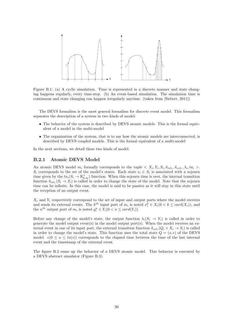
An event-based model considers that a system evolves in a continuous time base but changesits state at discrete points in time. These points are called event and can happen at any point insimulated time, contrary to cyclic model which change their states regularly every time-step (FigureB.1 ). Two types of events exist in event-based models: internal events and external events. Theformer correspond to events internally scheduled by the model, while the later correspond to:
• input events coming from other models or inputs generator, disturbing the model’s internalfunctioning,
• and output events send by the model to other ones or to some outputs analyzer.
A model sends an external event each time it changes its state. When a model receives an externalevent, it must process it. This action modifies the state of the model and may schedule new internalevent.
29
Figure B.1: (a) A cyclic simulation. Time is represented in a discrete manner and state chang-ing happens regularly, every time-step. (b) An event-based simulation. The simulation time iscontinuous and state changing can happen irregularly anytime. (taken from [Siebert, 2011])
The DEVS formalism is the most general formalism for discrete event model. This formalismseparates the description of a system in two kinds of model:
• The behavior of the system is described by DEVS atomic models. This is the formal equiv-alent of a model in the multi-model
• The organization of the system, that is to say how the atomic models are interconnected, isdescribed by DEVS coupled models. This is the formal equivalent of a multi-model
In the next sections, we detail these two kinds of model.
B.2.1 Atomic DEVS Model
An atomic DEVS model mi formally corresponds to the tuple < Xi, Yi, Si, δinti , δexti , λi, tai >.Si corresponds to the set of the model’s states. Each state si ∈ Si is associated with a sojourntime given by the tai(Si → R+
0,∞) function. When this sojourn time is over, the internal transitionfunction δinti(Si → Si) is called in order to change the state of the model. Note that the sojourntime can be infinite. In this case, the model is said to be passive as it will stay in this state untilthe reception of an output event.
Xi and Yi respectively correspond to the set of input and output ports where the model receivesand sends its external events. The kth input port of mi is noted xki ∈ Xi(0 < k ≤ card(Xi)), andthe nth output port of mi is noted yni ∈ Yi(0 < n ≤ card(Yi)).
Before any change of the model’s state, the output function λi(Si → Yi) is called in order togenerate the model output event(s) in the model output port(s). When the model receives an ex-ternal event in one of its input port, the external transition function δexti(Qi ×Xi → Si) is calledin order to change the model’s state. This function uses the total state Q = (s, e) of the DEVSmodel. e(0 ≤ a ≤ ta(s)) corresponds to the elapsed time between the time of the last internalevent and the timestamp of the external event.
The figure B.2 sums up the behavior of a DEVS atomic model. This behavior is executed bya DEVS abstract simulator (Figure B.3).
30
Figure B.2: Behavior of a DEVS atomic model (adapted from [Zeigler et al., 2000])
Figure B.3: An atomic DEVS model mi and its abstract simulator si
B.2.2 Coupled DEVS Model
In this section we present the formalism of a DEVS coupled model. DEVS supports hierarchicalmodeling thanks to its proved closure under the coupling property: to each coupled model cor-responds an atomic DEVS model. We present here a simplified, flattened version of the DEVScoupled model.
A DEVS coupled model is composed of a set M of interconnected models. An interconnectionis defined as a link between the output port of a DEVS atomic model, and the input port ofanother DEVS atomic model. The set of the coupled model’s links IC is composed of the couples((i, n), (j, k)), mapping the ports yni and xkj . When an external event is send out of an outputport, it must be immediately received in all the input ports sharing a link with this output port.Note that the DEVS formalism prevents an external input event from immediately generating anexternal output event. This may cause an immediate (in term of simulation time) infinite externalevents exchange between models, blocking the simulation execution. The figure B.4 shows an exam-ple of a DEVS coupled model. The table B.1 shows how this coupled model is formalized in DEVS.
An external event is composed of the tuple (t, e), where t corresponds to the timestamp of theevent, that is to say the (simulated) time where the event is sent. e corresponds to the eventmessage. It can be symbolic (i.e. describing the event in a symbolic way, like ’doors open’) ornumeric (i.e. describing the event in a quantitative way, like a set of positions).
Figure B.4: A DEVS coupled model composed of three DEVS atomic models: m1, m2 and m3
Links between the atomic models IC = {((1, 1), (2, 2)), ((1, 2), (3, 1)), ((2, 1), (1, 1)), ((3, 1), (2, 1))}
Table B.1: Formalization of the coupled model of figure B.4 in DEVS
B.3 Sequential execution of a coupled model
In this section, we present how a DEVS coupled model is sequentially simulated with a monolithicexecution. The simulation of a coupled model must respect the causality constraint, that is to say:
Definition: to respect the causality constraint, each atomic model must process its events(internals and externals) in an increasing temporal order [Zeigler et al., 2000,Fujimoto, 2001].
The sequential simulation of a DEVS coupled model is performed by a global coordinator (FigureB.5). It coordinates the DEVS simulators execution thanks to the maintainability of a global stackof the internal events scheduled for the simulation. These events are ordered according to theirtimestamps (Figure B.6).
Figure B.5: Sequential execution of the DEVS coupled model of figure B.4. A global DEVScoordinator manages the execution of the DEVS simulators.
The coordinator behavior follows the cycle:
1. Selection of the most imminent internal event to be processed in the simulation.
2. Processing of this event by the corresponding atomic model.
3. Propagation of the resulting external(s) event(s) in the coupled model.
4. Processing of the external events by the receiver(s) atomic model(s). This step potentiallylead to the scheduling of new internal event.
5. Updating the stack of events.
Figure B.6: Example of a stack of event for a sequential simulation of the coupled model of figureB.4. The events are arranged on the horizontal axis corresponding to the simulated time. Thecolor of each event corresponds to the model processing the event. (red for m1, blue for m2, andgreen for m3.)
32
Appendix C
Decentralized Execution of aDEVS Coupled Model withMECSYCO
This appendix is taken from [Camus et al., TBP].
C.1 Introduction
In this appendix, we explain the MECSYCO decentralized simulation algorithm based on theDEVS formalism (see Appendix B for more details on the DEVS formalism). In section C.2we show how MECSYCO represents a DEVS coupled-model. In section C.3, we describe theMECSYCO algorithm of execution for decentralized simulation of discrete-event system. Finally,in section C.4 we discuss the advantages of this algorithm for the multi-simulation of complexsystems.
C.2 Representation of a DEVS coupled model in MECSYCO
The translation of a DEVS coupled model, into the concepts of MECSYCO is done as fol-low [Siebert, 2011]. Each model mi is associated with an m-agent Ai thanks to an interfaceartifact Ii. The links between two models mi and mj corresponds a coupling artifact Cij betweenthe m-agents Ai and Aj (Figure C.1).
Figure C.1: The MECSYCO configuration corresponding to the coupled model of figure B.4
In MECSYCO, there is no DEVS global coordinator synchronizing the multi-simulation: the multi-simulation execution is done in a decentralized way by the m-agents. Therefore, the behavior of an
33
m-agent corresponds to the parallel abstract simulator of the model. In MECSYCO, an m-agentonly has a local knowledge of the coupled model’s links. It does not know neither the other m-agents nor their model’s input and output ports. The coupled model’s IC is split in the multi-model.An m-agent Ai only knows:
• which input coupling artifact has the event buffer of each of its model’s input ports. Wedefine the set of input links INi of Ai as being composed of the couples (j, k) mapping theinput coupling artifact Cji with the input port xki .
• to which output coupling artifact it must sends the external events of each of its model’soutput ports. We defines the set of output links OUTi of Ai as being composed of thecouples (n, j) mapping the ouput port yni with the output coupling artifact Cij .
The mapping of the output ports of a model mi with the input ports of a model mj is done by
the coupling artifact Cji . We defines the set Lij of links from mi to mj as being composed of the
couples (n, k) mapping the output port yni with the input port xkj . The table C.1 shows how thecoupled model of table B.1 is formalized in the MECSYCO formalism.
Descriptions NotationsOutput links of m1 OUT1 = {(1, 2), (2, 3)}Input links of m1 IN1 = {(2, 1)}
Output links of m2 OUT2 = {(1, 1)}Input links of m2 IN2 = {(1, 2), (3, 1)}
Output links of m3 OUT3 = {(1, 2)}Input links of m3 IN3 = {(1, 1)}
Links from m1 to m2 L12 = {(1, 2)}Links from m1 to m3 L13 = {(2, 1)}Links from m2 to m1 L21 = {(1, 1)}Links from m3 to m2 L32 = {(1, 1)}
Table C.1: Formalization of the coupled model of figure B.4 and Table B.1 in the MECSYCOformalism.
C.3 Decentralized simulation of a multi-model with MECSYCO
C.3.1 Issue of a distributed execution
In MECSYCO, there is no global coordinator for managing the execution of the global multi-simulation. According to the concept of agent, each m-agent is autonomous and manages only itsown model. The simulation of the multi-model is made thanks to a distributed execution of themulti-model.
The consequence of the memory distribution is that each m-agent only has access to the stackof events of its own model: the global stack of event is unknown (as illustrated in the figure C.2).The problem is that the information required for the coordination of the simulation execution issplit in the different m-agents. There is then a risk of breaking the causality constraint (i.e. thatthe events will be not processed in an increasing timestamp order).
34
Figure C.2: Example of the stacks of events for a distributed execution of the coupled model offigure B.4. The events are arranged on the horizontal axis corresponding to the simulated time.Each m-agent Ai can only know the stack of event of its model mi
Following a conservative approach in MECSYCO, all the m-agent have to be sure before anyprocessing to respect the causality constraint. As, the information required to ensure this pointis spread across several models (Figure C.2), the m-agents may be waiting on information of eachother. In this case, deadlock will occurs. Any conservative approach must then be proved to bedeadlock free.
We take the principle of the Chandy-Misra-Bryant algorithm [Chandy and Misra, 1979] for DEVS:in parallel of the external events flow, the temporal information required for the models synchro-nization is homogeneously disseminated in the multi-model during the simulation. In the followingwe present this algorithm. Proof that this algorithm is deadlock free and respect the causalityconstraint can be found in [Zeigler et al., 2000].
In the next sections, we detail how this algorithm works. In section C.3.2, we show how thisalgorithm ensures the respect of the causality constraint. The section C.3.3 details the processingof event. Sections C.3.4 and C.3.5 respectively detail the simulation initialization and stoppingcondition. The algorithm is detailed in section C.3.6.
C.3.2 Determining which events are safe to process
In order to fulfill the causality constraint, before processing any event (internal or external) with atimestamp t an m-agent has to be sure that no external input event will arrive with a timestampinferior to t. If an event fulfills this condition, it is then said safe to process.
In order to know which events are safe to process, each m-agent Ai needs to determine its es-timated earliest input time (EITi).
Definition: The EITi of an m-agent Ai corresponds to the (simulation) time below which itwill not receive any new external input event. All the events (internal or external) with atimestamp inferior or equal to this time are safe to process.
The computation EITi, is made possible thanks to the communication by all the m-agents of theirestimated Earliest Output Time (EOT). To determine EOTi, each m-agent Ai computes its looka-head.
35
Definition: The lookahead of an m-agent corresponds to the date (in simulation time),below which it guarantees it will not send new external output event (even if it receivesnew external input events). The lookahead of an m-agent Ai is then equal to the minimumbetween:
• the date of its model’s next internal event nti
• the date of its earliest (in term of simulation time) external event waiting to be pro-cessed in its input coupling artifacts tini
plus its model’s minimum delay transfer Dti.This date corresponds to the limit below which it is guaranty that all the alreadyreceived (but not processed yet) external events cannot schedule new internal events.
• the date of EITi plus its model’s minimum delay transfer Dti. This date correspondsto the limit below which it is guaranty that all the future external events that will bedropped in its input coupling artifacts cannot schedule new internal events
Dti(Dti > 0) corresponds to the minimum delay below which the processing of an externalevent cannot schedule a new internal event in mi. The Dti of each model in the multi-modelhas to be determined.
Lookaheadi = min(nti, EITi +Dti, tini +Dt)
Each m-agent updates its EOT in its output coupling artifacts, and can access to the EOT of theother m-agents with its input coupling artifacts. Therefore, each coupling artifact Cij proposes twofunctions to store and access to EOTi.
• Ai can use the setEOT operation to update EOTi in the artifact.
• Aj can use the getEOT operation to get EOTi.
The EITi of an m-agent Ai corresponds to the minimum EOT of the EOTs given by all the inputcoupling artifacts of Ai.
C.3.3 Processing safe events
In order to process safe events in a temporal increasing order, the behavior of an m-agent Ai
follows the cycle:
1. Get the time nti of its next internal event (nti ∈ R).
2. Get the time tini of the earliest external event of all its input coupling artifacts eini . (nti ∈ R)
3. Determine what is the earliest event between the next internal event or eini.
4. Determine if this event is safe to process.
5. If yes, process the earliest event.
6. If this event is an internal event, propagate the resulting output external events to otheragents.
C.3.4 Initialization of the simulation
We assume here that the distributed simulations begin at simulation time 0. Before starting thedistributed simulation, each model may be initialized using information dependent on some othermodels. In other word, the models need to send and integrate external events of initialization. Theinitialization phase allows models to send external events to other models.
As these events are for the initialization of the multi-model, they must happen before (in term ofsimulation time) the beginning of the simulation. That is why the timestamp of every initializationevents must be strictly inferior to 0. The coupling artifacts’ original E0Ts are equals to −∞ to
36
prevent the m-agents from starting processing their model’s internal events before receiving theirinitialization ones. When each m-agent has sent all its initialization events, it sets its output cou-pling artifacts’ EOT to 0. This procedure guaranties that each m-agent integrates its initializationinput event before processing the simulation ones. Figure C.3 illustrates this initialization phase.
Figure C.3: Example of the initialization phase. Planned internal events are on the time axis(horizontal). Each vertical arrow shows the sending of an external event. Events outside thedarkest zone are secured events. Step 1: Link Times are fixed at −∞. M-Agents cannot processthe internal events of their models. Step 2: M-Agents that need to send initialization events, sendthem. Step 3: All initialization events are sent, agents are now fixing the Link Times of theircoupling artifact (sender) to 0.
C.3.5 Stopping condition for the end of the simulation
We consider here that we want to simulate the system up to time Z (Z ∈ R). Two conditions existin order to determine when the end of the simulation is reached. An m-agent stops the simulationwhen all of these two conditions are respected:
• It has processed all its model’s internal events up to simulation time Z. This condition isobserved when EOTi > Z.
• It has processed all its external events up to simulation time Z. This condition is heededwhen:
– It has received all the external events up to Z (EITi > Z).
– It has processed all of these events (tini> Z ).
C.3.6 The behavior of the m-agents
The table C.2 sums up the notations of the MECSYCO meta-model. Tables C.3 and C.4 respec-tively shows the operations proposed by the coupling and the interface artifacts. The algorithm 1describes the m-agent behavior.
37
Figure C.4 describes an example of distributed simulation execution of the coupled model of figureB.4. The values of the simulation’s parameters for this example are described by table C.5. Thestate of the m-agents is described in table C.6. For sake of simplicity, we assume in that examplethat external events do not schedule new internal event in the models.
Level Description Notation
ConceptualM-agent Ai
Interface artifact IiCoupling artifact from Ai to Aj Cij
Semantic
Model mi
Input links of mi INi
Ouput links of mi OUTi
Links between mi’s output and mj ’s input Lij
Syntactic
Set of mi’s input ports Xi
Set of mi’s output ports Yikth input port of mi xki (0 < k ≤ card(Xi))nth output port of mi yni (0 < k ≤ card(Yi))
Dynamic
Maximum simulation time ZSimulation time ti
Time of the next internal event of mi ntiTime of earliest external input event of mi tini
Earliest estimated input time of mi EITi
Earliest estimated output time of mi EOTi
Earliest external input event of mi eini
External output event of port yni enouti
Table C.2: Notations of the MECSYCO meta-model
Operations Descriptionpost(enouti , ti) Sends the external event enouti at time ti
getEarliestEvent(k) Returns the earliest external event at the input port xki (or nullif they is no external event)
getEarliestEventT ime(k) Returns the time of the earliest external event at the input portxki (or +∞ if they is no external event)
removeEarliestEvent(k) Removes the earliest external event for the port xkisetEOT (ti) Sets the time of the earliest estimated output time at time tigetEOT () Returns the time of the earliest estimated output time of the cou-
pling artifact
Table C.3: Operations proposed by the coupling artifacts
Operations Descriptioninit() Initializes the simulator and sets the model’s parameters
getNextInternalEventT ime() Returns the time of the next internal event of mi
getExternalOutputEvent(yni ) Returns the external output event of the output port yniprocessExternalInputEvent(eini
, ti, xki ) Processes the external input event eini
at time ti in the input portxki
processInternalEvent(ti) Processes the internal event scheduled at time ti
Table C.4: Operations proposed by the interface artifacts
38
Parameters ValuesDt1 3Dt2 2Dt3 1Z 12
Table C.5: Parameters of the simulation Figure C.4.
Table C.6: State of the m-agents from the simulation Figure C.4. Asterisk point out that EOTi =tni. Else, EOTi = EITi +Dti.
Figure C.4: Example of a run of a distributed simulation of a multi-model. Planned internalevents are on the time axis (horizontal). Each vertical arrow shows the sending of an externalevent. Events outside the darkest zone are secured events.
39
Algorithm 1 Algorithm of the m-agent’s behavior
INPUT: INi, OUTi, Z,DtiOUTPUT:
nti ← Ii.getNextEventT ime()tini← +∞
EOTi ← 0EITi ← 0
. Until all internal and external events have been processed up to Z, dowhile (EOTi ≤ Z) or (EITi ≤ Z) or (tini ≤ Z) do
nti ← Ii.getNextInternalEventT ime()EITi ← +∞tini← +∞
for (j, k) ∈ INi doif Cji .getEOT () < EITi then . Compute the EIT
EITi ← Cji .getEOT ()end ifif Cji .getEarliestEventT ime(k) < tini
then . Get the earliest input event
tini ← Cji .getEarliestEventT ime(k)
eini← Cji .getEarliestEvent(k)
p← kc← j
end ifend for
. If there is, process the earliest safe event (internal or external)if (nti ≤ tini
) and (nti ≤ EITi) and (nti ≤ Z) then . If it is an internal eventIi.processInternalEvent(nti) . Process the internal eventnti ← Ii.getNextInternalEventT ime()for n ∈ [1, card(Yi)] do . Send the resulting external events
≤ Z) then . If it is an external eventIi.processExternalInputEvent(eini
, tini, xpi ) . Process the external event
Cci .removeEarliestEvent(p)nti ← Ii.getNextInternalEventT ime()
end if. Compute the EOT and update the output coupling artifacts
tini← +∞ . Get the earliest input event time
for (j, k) ∈ INi doif Cji .getEarliestEventT ime(k) < tini then
tini← Cji .getEarliestEventT ime(k)
end ifend forif EOTi 6= Lookaheadi(nti, EITi, tini) then . Update the output coupling artifacts
EOTi ← Lookaheadi(nti, EITi, tini)
∀(k, j) ∈ OUTi : Cij .setEOT (EOTi)end if
end while
40
C.4 Discussion
An advantage of this algorithm is that it allows the integration of different scheduling policies:
• If the model is discrete in time, the simulator cannot advance the simulation time between twointernal events. In consequence, the processExternalInputEvent operation only computesthe external event in the model without changing the time of the model. This may lead toslight errors in the simulation results, but they are inherent to a discrete time representationof the system.
• Cyclic time-step models can be considered as discrete event models with internal event sched-uled in a regular manner in simulation time. For these models, the getNextInternalEventT imecan simply return the current time of the model plus the size of a time-step. In this case,the processInternalEvent operation executes the model for one simulation step.
• If external events cannot schedule new internal event in a model mi, then Dti = +∞. As aconsequence, EOTi will always be equal to tni.
Moreover, this algorithm takes directly account of the dependencies between models. Indeed, if amodel mi does not have any input link, then EITi = tini
= +∞. The m-agent will then alwayscompute all its model’s internal events and propagate the resulting external events as fast as it canuntil EOTi > Z.
41
Bibliography
[Blochwitz et al., 2011] Blochwitz, T., Otter, M., Arnold, M., Bausch, C., Clau, C., Elmqvist,H., Junghanns, A., Mauss, J., Monteiro, M., Neidhold, T., and et al. (2011). The functionalmockup interface for tool independent exchange of simulation models. In 8th InternationalModelica Conference, Dresden.
[Camus et al., TBP] Camus, B., Bourjot, C., and Chevrier, V. ((TBP)). An execution algorithmfor distributed discret-event simulation with aa4mm. Technical report, Universite de Lorraine.
[Chandy and Misra, 1979] Chandy, K. M. and Misra, J. (1979). Distributed simulation: A casestudy in design and verification of distributed programs. Software Engineering, IEEE Transac-tions on, (5):440–452.
[ECMA, 2013] ECMA (2013). Ecma-404 the json data interchange standard. 1st edition.
[Fishwick, 2007] Fishwick, P. A. (2007). Handbook of dynamic system modeling. CRC Press.
[Fujimoto, 2001] Fujimoto, R. M. (2001). Parallel simulation: parallel and distributed simulationsystems. In Proceedings of the 33nd conference on Winter simulation, WSC ’01, pages 147–157,Washington, DC, USA. IEEE Computer Society.
[OMG, 2007] OMG (2007). Data distribution service (dds), version 1.2.
[Quesnel et al., 2009] Quesnel, G., Duboz, R., and Ramat, E. (2009). The virtual laboratoryenvironment – an operational framework for multi-modelling, simulation and analysis of complexdynamical systems. Simulation Modelling Practice and Theory, 17(4):641 – 653.
[Ricci et al., 2007] Ricci, A., Viroli, M., and Omicini, A. (2007). Give agents their artifacts: thea&a approach for engineering working environments in mas. In Proceedings of the 6thinternational joint conference on Autonomous agents and multiagent systems, AAMAS ’07, pages150:1–150:3, New York, NY, USA. ACM.
[Siebert, 2011] Siebert, J. (2011). Approche multi-agent pour la multi-modelisation et le couplagede simulations. Application a l’etude des influences entre le fonctionnement des reseaux ambiantset le comportement de leurs utilisateurs. These, Universite Henri Poincare - Nancy I.
[Vangheluwe, 2000] Vangheluwe, H. (2000). Devs as a common denominator for multi-formalismhybrid systems modelling. In Computer-Aided Control System Design, 2000. CACSD 2000.IEEE International Symposium on, pages 129–134.
[Vangheluwe et al., 2002] Vangheluwe, H., De Lara, J., and Mosterman, P. J. (2002). An intro-duction to multi-paradigm modelling and simulation. In Proc. AIS2002. Pp, pages 9–20.
[Zeigler et al., 2000] Zeigler, B., Praehofer, H., and Kim, T. (2000). Theory of Modeling andSimulation: Integrating Discrete Event and Continuous Complex Dynamic Systems. AcademicPress.