1 Multi-carrier CDMA (MC-CDMA) with Space time codes 1. Introduction: • Most of the codes provide high reliability but have a low data rate. Hence, it is clear that the codes with high rate and reliability are the design target in minds of most researchers. • To provide high transmission bandwidth efficiency in mobile communications, multiplexing schemes are introduced such as direct-sequence code division multiple access (DS-CDMA), orthogonal frequency division multiplexing (OFDM). • These techniques are mostly considered in the time and frequency domain. In addition, we can consider the space domain to improve the performance, i.e. space-time coded modulation (STCM), array techniques. Thus, the combination of coding and multiplexing may provide better performance if they are considered in space domain as well. • Multi-carrier code division multiple access (MC-CDMA) takes the advantages from the combinations of both DS-CDMA and OFDM considering mobile communication in multi-path fading channels. • STCM can guarantee that the diversity occurs at transmitting side and maximizes both coding gain and diversity gain. Consequently, this modulation scheme has a capability of combating the multipath fading in wireless communications (Naguib et al, 1998, 1997). Objectives: • Performance of space-time coded MC-CDMA is evaluated over slow frequency-selective fading channel • Performance of MC-CDMA with STCM employing multiple transmit antennas and TCM with single antenna are compared with respect to the complexity and spectral efficiency of the codes Assumptions: • Number of users is limited to sixteen users in the fading channel. • Urban or suburban area is the environment of interest. • Ideal channel estimation is assumed. • Frequency offset and peak-to-average power ratio are not considered in this thesis. • The data rate of every user is assumed to be equal. • Time and frequency synchronization is assumed in downlink communications. • Delay between each tap in the channel model is assumed to equals to sampling period.
Transcript
1
Multi-carrier CDMA (MC-CDMA) with Space time codes
1. Introduction:
• Most of the codes provide high reliability but have a low data rate. Hence, it is clear thatthe codes with high rate and reliability are the design target in minds of most researchers.
• To provide high transmission bandwidth efficiency in mobile communications,multiplexing schemes are introduced such as direct-sequence code division multipleaccess (DS-CDMA), orthogonal frequency division multiplexing (OFDM).
• These techniques are mostly considered in the time and frequency domain. In addition,we can consider the space domain to improve the performance, i.e. space-time codedmodulation (STCM), array techniques. Thus, the combination of coding and multiplexingmay provide better performance if they are considered in space domain as well.
• Multi-carrier code division multiple access (MC-CDMA) takes the advantages from thecombinations of both DS-CDMA and OFDM considering mobile communication inmulti-path fading channels.
• STCM can guarantee that the diversity occurs at transmitting side and maximizes bothcoding gain and diversity gain. Consequently, this modulation scheme has a capability ofcombating the multipath fading in wireless communications (Naguib et al, 1998, 1997).
Objectives:
• Performance of space-time coded MC-CDMA is evaluated over slow frequency-selectivefading channel
• Performance of MC-CDMA with STCM employing multiple transmit antennas and TCMwith single antenna are compared with respect to the complexity and spectral efficiencyof the codes
Assumptions:
• Number of users is limited to sixteen users in the fading channel.• Urban or suburban area is the environment of interest.• Ideal channel estimation is assumed.• Frequency offset and peak-to-average power ratio are not considered in this thesis.• The data rate of every user is assumed to be equal.• Time and frequency synchronization is assumed in downlink communications.• Delay between each tap in the channel model is assumed to equals to sampling period.
2
2. MC-CDMA Overview
• The multi-carrier CDMA schemes are mainly categorized into two groups.• One spreads the original data stream using a given spreading code, and then modulate a
different subcarriers with each chip (in a sense, the spreading operation in the frequencydomain) (Yee et al., Fazel and Papke, Chouly et al., 1993),
• and another spreads the serial-to-parallel converted data streams using a given spreadingcode, and then modulates different subcarriers with each data stream (the spreadingoperation in time domain) (DaSilva and Sousa, Vandedrope, 1993), similar to a normalDS-CDMA scheme.
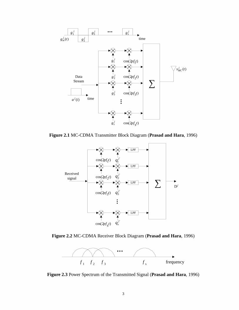
• Here MC-CDMA transmitter which spreads the original data stream over differentsubcarriers using a given spreading code in the frequency domain is considered.
• In a (synchronous) down link mobile radio communication channel, we can use theWalsh-Hadamard codes as an optimum orthogonal set, because we do not pay attention tothe auto-correlation characteristic of the spreading code. The Figure 2.1 and 2.3 show theMC-CDMA transmitter for coherent binary phase shift keying (CBPSK) scheme and thepower spectrum of the transmitted signal respectively.
The transmitted signal of the jth user is written as
})(2cos{)()()( 01
tfmfiTtpgiats ssi
G
m
jm
jjMC
MC
∆+−⋅= ∑ ∑∞
− ∞= =π (2.1)
where ∆f (= 1/Ts) is the subcarrier separation, jmc is the spreading code at mth subcarrier, aj(i)
is the original data stream at time i, ps(t) is the pulse wave form defined as:
≤≤=
otherwise0
0for1)( sTttps (2.2)
• The main advantage of MC-CDMA scheme over other schemes (DS-CDMA, MC-DS-CDMA or MT-CDMA) is that the MC-CDMA receiver can always use the all receivedsignal energy scattered in the frequency domain to detect the desired signal. However,through a frequency-selective fading channel, the subcarriers may have differentamplitude level and phase shifts (although they have high correlation among subcarriers),and it results in the distortion of orthogonality among users.
3
time
∑)2cos( 2tfπ
)2cos( 3tfπ
)2cos( 1tfπ
)2cos( tsfπ
DataStream
time
)(tg jm
jg1jg2
jg3jsg
jg1
jg3
jsg
)(ts jMC
)(ia j
jg2
Figure 2.1 MC-CDMA Transmitter Block Diagram (Prasad and Hara, 1996)
∑Received
signal
Dj'
)2cos( 2tfπ
)2cos( 3tfπ
)2cos( 1tfπ
)2cos( tsfπ
LPF
LPF
LPF
LPF
'1jq
'2jq
'3jq
'jsq
Figure 2.2 MC-CDMA Receiver Block Diagram (Prasad and Hara, 1996)
f 1 f 2 f 3 f s frequency
Figure 2.3 Power Spectrum of the Transmitted Signal (Prasad and Hara, 1996)
4
• Figure 2.2 shows the MC-CDMA receiver of the th'j user, the mth subcarrier is multipliedby the gain 'j
mq , which is the combination of the spreading code of the subcarrier fm withthe corresponding subchannel gain. The decision variable is given by (ignoring thesubscription i without loss of generality)
mj
mj
J
j
jmm
m
G
m
jm
j
ncazy
yqDMC
+=
=
∑
∑
=
=
1
1
''
(2.3)
- where ym and nm are the complex baseband component of the received signal, whichthere are the properties of subcarrier frequency synchronization and the complex additiveGaussian noise after down conversion at the mth subcarrier, respectively, j
mz is thecomplex envelop of the mth subcarrier for the jth user. We can assume
Jjzz mj
m ,,2 1,for L== in a down-link channel.
• It is crucial for multicarrier transmission to have frequency flat fading over eachsubcarrier.
• Then, if the original symbol rate is high enough to experience with frequency selectivefading, the signal needs to be first serial-to-parallel converted before spreading over thefrequency domain. Additionally, the proper choice of the number of subcarriers and theguard interval is important to increase the robustness against frequency selective fading.
• However, the problems of frequency offset and peak-to-average power ratio should alsocarefully be considered when choosing the number of subcarriers and the subcarrierbandwidth.
General MC-CDMA System Implementation
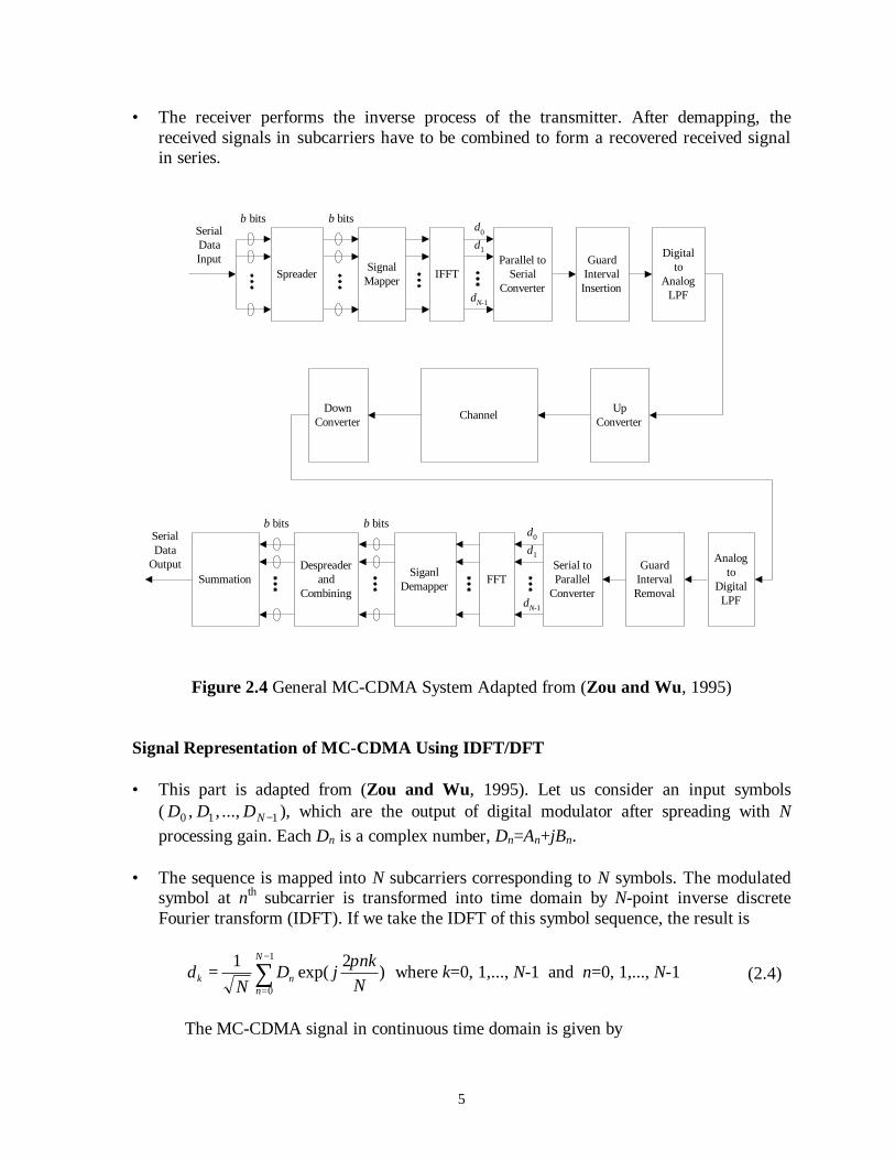
• Figure 2.4 illustrates the typical MC-CDMA system. The incoming serial data is firstcopied from serial to form N parallel data streams and grouped into b bits. Each of b bitsis spread over frequency domain and formed to be a complex number. The complexnumbers are modulated in a baseband fashion by the IFFT and converted back to serialdata for transmission. A guard interval consisting of a partial repetition of the output ofthe IDFT process (dk) is inserted between symbols to avoid intersymbol interference (ISI)caused by multipath distortion. The discrete symbols are converted to analog by lowpassfiltering and then feed to RF up-converter.
5
• The receiver performs the inverse process of the transmitter. After demapping, thereceived signals in subcarriers have to be combined to form a recovered received signalin series.
SignalMapper IFFT
Parallel toSerial
Converter
GuardIntervalInsertion
Digitalto
AnalogLPF
DownConverter
UpConverterChannel
Analogto
DigitalLPF
GuardIntervalRemoval
Serial toParallel
ConverterFFTSiganl
DemapperSummation
SerialDataInput
SerialData
Output
d0
d1
dN-1
b bits
b bitsd0
d1
dN-1
Spreader
b bits
Despreaderand
Combining
b bits
Figure 2.4 General MC-CDMA System Adapted from (Zou and Wu, 1995)
Signal Representation of MC-CDMA Using IDFT/DFT
• This part is adapted from (Zou and Wu, 1995). Let us consider an input symbols( 110 ..., , , −NDDD ), which are the output of digital modulator after spreading with Nprocessing gain. Each Dn is a complex number, Dn=An+jBn.
• The sequence is mapped into N subcarriers corresponding to N symbols. The modulatedsymbol at nth subcarrier is transformed into time domain by N-point inverse discreteFourier transform (IDFT). If we take the IDFT of this symbol sequence, the result is
∑−
==
1
0
)2
exp(1 N
nnk N
nkjD
Nd
πwhere k=0, 1,..., N-1 and n=0, 1,..., N-1 (2.4)
The MC-CDMA signal in continuous time domain is given by
6
∑−
==
1
0
)exp()(N
nnn tjDtY ω , where nn fπω 2= (2.5)
The sampled signal of Y(t) at sampling rate 1/T is
∑−
==
1
0
)exp()(N
nnn kTjDkTY ω (2.6)
• If we restrict the time over which we analyze the signal to N samples with sampling rate1/T, then the total MC-CDMA symbol period sT equal to NT, and nffn ×∆= . Where
f∆ is the frequency spacing between sub-carriers. If we take sTNTf /1/1 ==∆ then
k
n
N
nn
N
nn
N
nn
N
nnn
dN
DIDFTN
NnkjD
NTnkT
jD
fkTnjD
kTjDkTY
×=×=
=
=
∆=
=
∑
∑
∑
∑
−
=
−
=
−
=
−
=
}{
)2exp(
)2
exp(
)2exp(
)exp()(
1
0
1
0
1
0
1
0
π
π
π
ω
(2.7)
• It is therefore clear, from Equation (2.4), that IDFT can be used to modulate the MC-CDMA signal. Finally, the samples kd are transmitted using ordinary T-spaced pulseamplitude modulation.
7
Walsh-Hadamard Codes for Orthogonal Design • In MC-CDMA scheme, Walsh-Hadamard codes are used for the frequency spread coding
to achieve the orthogonality among users.• This code is simply obtained by selecting as codewords, the rows of Hadamard matrix.
+1 and –1 denote the elements of the Hadamard matrix. The Hadamard matrix Hn is annn× matrix such that n is an even integer with the property that any row differs from
any other rows in exactly n/2 positions. Usually, the first row of the matrix contains all+1s. The other rows contain +1s of n/2 and -1s of n/2. The rows of the Hadamard matrixare then mutually orthogonal. To generate the code, the fundamental unit of Hadamardmatrix is given as
−=
1111
2H (2.8)
• The following recursive matrix operation is employed to produce the Walsh-Hadamardcodes of length 2n.
−=
nn
nnn HH
HHH2 (2.9)
- where the matrix, H2n, of the size nn 22 × is formed by using the matrix, Hn, of sizenn× with H2 given above. These codes fulfill completely the orthogonality between
each other when synchronization is regularly held.
8
3. Simulation Configuration
• The downlink of MC-CDMA system is considered. The block diagram of lowpassequivalent representation of the overall simulation model is shown in Figure 3.1.
Figure 3.1 Block Diagram of Lowpass Equivalent System Model Followed forMonte Carlo Simulation Implementation
• In the simulation, FER is used for comparison. One frame in this simulation is equal to256 bits or 128 symbols. The comparison is made on the error of bit in each frame. Ifthere is any bit error in a frame, that frame will be taken to be a frame error.
Transmitter Section
• At the transmitter, the proposed system employs STCM encoder considering fourtransmitting and one receiving antennas. Each branch at the output of the encoder has aninterleaver with block size corresponding to one-frame symbols. After that the MC-CDMA scheme, is used to both multiplexing and modulating the interleaved codedsymbol.
RandomData
Generator
Interleaver
Interleaver
STCMEncoder
Interleaver
Interleaver
Tx MC-CDMA Fading Channel
Fading Channel
Fading Channel
Fading Channel
AWGN
Tx MC-CDMA
Tx MC-CDMA
Tx MC-CDMA
Rx MC-CDMADeinterleaverSoft Input
ViterbiDecoder
Delay
Comparison
FER Output
Transmitter MobileRadio
Channel
Receiver
9
Encoder
• STCM code can be viewed as delay diversity code with four transmit antennas andQPSK modulation. The number of states in a trellis diagram is at least 64 states and theconstraint length, the minimum number of bits on a single output stream that can beaffected by any input bit, of the encoder is three.
• Therefore, the total number of memory, the number of shift register elements, for encoderis equal to six. As the number of memory increases, the number of possible states of theencoder increases, making a higher complexity in the Viterbi decoder at the receiver.Figure 3.2 shows an implementation of STCM encoder.
Figure 3.2 STCM Encoder Block Diagram
• It can be shown that this code guarantees a diversity advantage of 4 and coding advantageof 16 from the trellis diagram of the code.
• For comparison, trellis coded modulation (TCM) (Schlegel and Costello, 1989) isapplied. instead of Ungerboeck’s codes, which are designed to have the maximumEuclidean distance.
• Ihis TCM scheme is designed for fading channel, which maximize the minimum symboldistance or Hamming distance (dH) and the minimum product distance ( 2
pd ) andminimize the path multiplicity (Schlegel and Costello, 1989). The roles of thesedesigning parameters also vary depending on the level of SNR (Ha and Rajatheva,1998). Given the same decoding complexity, a 64 states with code rate 2/3 8-PSK isutilized. The specification of the code is given in Table 3.1.
kx2kx1
kx3kx4
}Branches Corresponding to
4 Transmitting Antennas}
D
D
D D
DD
ak
bk
ak-1
bk-1
ak-2
bk-2
ak-3
bk-3
2 1 1 2 2 3 3 1Operation of the Ring of
Integer Modulo 4
10
Table 3.1 Specification of Rate 2/3 8-PSK TCM Code Used for Comparison
CodeIdentification h(0) h(1) h(2) Mapping dH
2pd
64 States 103 036 154 Natural 4 8
• In Table 3.1, the encoder polynomials h(0), h(1) and h(2) are in octal form. The mapping to8-PSK signal constellation is natural mapping. The TCM encoder block diagram is givenin Figure 3.3.
Figure 3.3 Feed Back Realization of 8-PSK, 64 States Trellis Code
Interleaver
• A rectangular-array symbol interleaver consisting of 8 rows and 16 columns is utilized.A128 symbols interleaver is shown in Figure 3.4.
Figure 3.4 128 Arrays Symbol Interleaver
T T T T TT
8-PSKMapper
x(1)
x(0)
c(2)
c(1)
c(0)
h(0)
h(1)
h(2)
Read out symbols to modulator, one row at a time
12
9
8 128
10
16
8 rows
16 columns
Read incodedsymbolsfromencoder
11
Tx MC-CDMA
• It is crucial for multicarrier CDMA to have frequency-flat fading in each subchannel. Ifthe data rate is high enough to have frequency-selective fading, the system needs to useserial-to-parallel conversion before spreading. The number of subcarriers is equal to 128to satisfy the data rate and required bandwidth. To determine the maximum number ofuser to 32, the processing gain for spreading codes is 32. Figure 3.5 shows the consideredTx MC-CDMA.
time
IFFT
DataStream
time
)(' tg kn
'0kg
'1kg
'2kg '
31kg
'0kg
'4kg
'31kg
)(tx
)(' lck
'1kg
Other Users
S/P
Figure 3.5 Tx MC-CDMA in the Simulation
Receiver Section
• At the receiver, the Rx MC-CDMA is employed to recover the information of the desireduser by using FFT and multiply the receive signal with the specific spreading code. Thedeinterleaver is needed to rearrange the symbols into an appropriate way, which is theinverse version of the interleaver. The soft input Viterbi decoder is employed toreconstruct the transmitted signal from the noisy faded received signal.
12
Maximum Likelihood Decoder
• When the perfect channel estimation is assumed and only one receive antenna is used, thechannel parameters i
nH for i = 0, 2,..., 3 and n = 0, 2,..., 127 is available at the receiver.Then we can derive the maximum likelihood decoding rule for space-time code (Naguibet al., 1998) as follows.
• Supposing that a code vector sequence given as
lNtttt ccc cccc c LL 21
21 , == (3.1)
has been transmitted and a received vector sequence given as
ltt r rrrr r L21, == (3.2)
has been received, where tr is given in Equation (2.10). It is easily to see that
tttst HE ncr +⋅⋅= . At the receiver, the optimum decoding has designed to choose adecoded vector sequence
lNtttt eee eeee e LL 21
21 , == (3.3)
for which a posteriori probability is maximized. Assuming that all code words areequiprobable and noise vector is a multivariate additive white Gaussian noise, then thedecoded vector can be written as
2127
0
3
0
31
0,
1min ∑ ∑ ∑= = =
−=
t i n
itn
it
MCt He
Gre (3.4)
- where |||| ⋅ denotes the Euclidean norm. It is obvious that the optimum decoding rule in(3.4) can be implemented by using Viterbi algorithm, which is used to compute the pathwith the lowest metric, when the space-time code has a trellis representation.
• In the practical case, the receiver has to estimate the channel state information (CSI). Theabove equation will be changed due to CSI estimation error. Thereby the performance ofSTCM will be limited by property of CSI estimation.
• However (Naguib et al., 1998), for the case of constant envelope signals such PSK, thedecoding rule is still optimum even in the presence of channel estimation error. For QAMsignals, the rule is still valid only if the system is assumed to use ideal CSI, or when thechannel estimation error is negligible compared to the channel noise.
13
Multiuser Receiver
• The block diagram of multiuser receiver is shown in Figure 3.6. The first stage of thereceiver is parallel interference canceller, which generates interference free statistics toestimate the transmitted bits for paticular user. The final stage is the conventionaldetector. Each of them is used for one user.
ParallelInterence
Cancellation
STCMDecoder
STCMDecoder
STCMDecoder
STCMEncoder
STCMEncoder
STCMEncoder
r(t)
y1
y2
yK
1b
2b
Kb
1c
2c
Kc
Figure 3.6 Block Diagram of PIC Multiuser Receiver
• Parallel processing of multiuser interference canceller removes the interference, beingproduced by the remaining users accessing the channel, from each user to estimate theinterference free statistics of the transmitted bits for all users (Nghia, 1999). In thesimulations, we focus on the last user without loss of generality. For multistage PICtaking channel fading into account, the MAI estimated at jth stage can be expressed as
∑∑ ∑=
−−
= =−=
3
0
)1(,
1
1 1
)(1 )(ˆ)()(ˆ
i
jki
K
k
L
iskk
j lclTtglHI (3.5)
where )(ˆ )(, lc jki is the estimated of )(, lc ki of user k at l symbol interval at stage j.
• At the j stage, the estimated MAI is completely removed from the received signal. Thisprocess can be written as
)(1
)(1
ˆ)( jjc Itrr −= (3.6)
14
Channel Model
• The equivalent discrete-time channel model representing the overall transmission modelin this thesis study is shown in Figure 3.7.
D D D
∑From Other
Transmit Antennas
)(, kx mi
0kf 1
kf2
kf3
kf )(knm
Received Signal)(krm
Transmitted Signal
Figure 3.7 Tapped-Delay Line Channel Model under Consideration
To apply it in MC-CDMA system, the tap gain lkf of the channel from a transmit to a
receive antenna can be expressed as
( ) )(2exp1
lim1
nsamp
N
nsDnN
lk lTkTfj
Nf
nτδπθ −⋅+= ∑
=∞→(3.7)
- where the delays between taps are equal to sampling period (Tsamp) with uniformlymultipath intensity profile and Ts denotes the symbol period. From the central limittheorem, the magnitude and phase of the tap gain are Rayleigh and uniform distributedbut the power spectrum density follows the classical Doppler spectrum.
Figure 3.8 Frequency Response of the Tap Gain
Doppler Spectrum
0
2
4
6
8
-0.6 -0.4 -0.2 0 0.2 0.4 0.6
Normalized Frequency
Amp.150,000 SamplesIdeal Response
15
• In this study, the multipath intensity profile is assumed to be uniform. The total averagepower of the channel is normalized to unity.
∑−
==
1
0
2 12L
nnσ (3.8)
where nσ is the standard deviation for both real and imaginary parts in each tap.
4. Simulation Results:
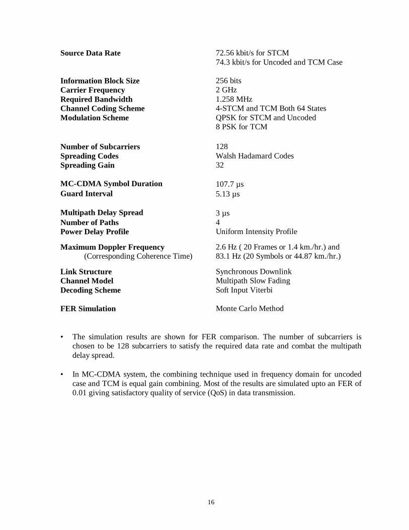
• This section presents the simulation results of the proposed system over slowlyfrequency-selective fading channel. By assuming a multipath channel model with asymbol spaced tapped-delay line for typical suburban environment, we can model thechannel with 4 taps. Parameters and system configurations for the proposed system usedin this thesis study are summarized below. In this thesis, the parameters are selected to bematched to the third generation standard.
16
Source Data Rate 72.56 kbit/s for STCM74.3 kbit/s for Uncoded and TCM Case
Information Block Size 256 bitsCarrier Frequency 2 GHzRequired Bandwidth 1.258 MHzChannel Coding Scheme 4-STCM and TCM Both 64 StatesModulation Scheme QPSK for STCM and Uncoded
8 PSK for TCM
Number of Subcarriers 128Spreading Codes Walsh Hadamard CodesSpreading Gain 32
MC-CDMA Symbol Duration 107.7 µsGuard Interval 5.13 µs
Maximum Doppler Frequency(Corresponding Coherence Time)
2.6 Hz ( 20 Frames or 1.4 km./hr.) and83.1 Hz (20 Symbols or 44.87 km./hr.)
Link Structure Synchronous DownlinkChannel Model Multipath Slow FadingDecoding Scheme Soft Input Viterbi
FER Simulation Monte Carlo Method
• The simulation results are shown for FER comparison. The number of subcarriers ischosen to be 128 subcarriers to satisfy the required data rate and combat the multipathdelay spread.
• In MC-CDMA system, the combining technique used in frequency domain for uncodedcase and TCM is equal gain combining. Most of the results are simulated upto an FER of0.01 giving satisfactory quality of service (QoS) in data transmission.
17
Figure 4.1 shows the FER performance of MC-CDMA over AWGN channel for 32 users.
Figure 4.1 FER Comparison of Coded and Uncoded MC-CDMA 32 Usersover AWGN Channel
• Both STCM coding schemes cannot achieve a gain over uncoded one and TCM (Schlegeland Costello, 1989) designed for fading channel achieves the best performance.(overAWGN channel) TCM can obtain a gain of around 3.5 dB SNR at FER of 0.01 beyonduncoded case and around 4 dB SNR at the same FER beyond both STCM codes. After 9dB SNR, the performance of 2-STCM (2 antennas) is better than 4-STCM (4 antennas).
0.001
0.01
0.1
1
2 3 4 5 6 7 8 9 10
Eb/No (dB)
FERQPSK Uncoded
4-STCM 64 States QPSK
2-STCM 4 States QPSK
TCM 64 States 8 PSK (Schlegeland Costello, 1989)
18
• Figure 4.2 shows the FER performance of coded and uncoded single user systemperturbed by frequency-flat fading with the transmission rate is lower than coherencebandwidth of the channel.
Figure 4.2 FER Comparison of Coded and Uncoded Single User over Slow Flat Fadingwith coherence time of 20 Frames
• Both STCM coding schemes achieve a gain over uncoded scheme and TCM code(Schlegel and Costello, 1989). With the same decoding complexity (APPENDIX D), 4-STCM can gain about 4 dB in SNR at FER of 0.07 compared to TCM. Moreover, 2-STCM (4 states) also has gain about 1.5 dB in SNR at 0.07 FER over TCM 64 states.When compare to the uncoded case, There is more than 2 dB gain in SNR at 0.1 FER for2-STCM 4 states and 5 dB gain in SNR at 0.1 FER for 4-STCM (64 states). Therefore, ifthe application of interest is satisfied at 0.01 FER, we can expect more gain in STCMsystem over flat fading channel.
• Consequently, the performance of STCM code when no multiple access scheme isconsidered outperforms TCM code.
0.01
0.1
1
9 10 11 12 13 14 15 16 17 18
Eb/No (dB)
FERUncoded QPSK
2-STCM 4 States
4-STCM 64 States
TCM 64 States 8-PSK (Schlegeland Costello, 1989)
19
• Figure 4.3 shows the performance of MC-CDMA using 4-STCM (64 states) compared touncoded case for different numbers of users over multipath channel with 20 framescoherence time.
Figure 4.3 FER Comparison of 4-STCM and Uncoded MC-CDMA over Slowly VaryingFrequency-Selective Fading channel with coherence time of 20 Frames
• There is about 3-dB gain for 4 users case but no gain in the case of 8 users or more.When the number of user is more than 8, it can be seen from the Figure 4.3 that theperformance of STCM-MC-CDMA is much worse than the uncoded case with thecorresponding number of users.
• MAI is a main problem in multiplexing system especially CDMA. We can say that due tothe lack of combining techniques in the proposed system, MAI can destroy the proposedsystem performance.
0.01
0.1
1
14 15 16 17 18 19 20 21 22 23Eb/No (dB)
FER
Uncoded 4 Users
Uncoded 8 Users
Uncoded 16 Users
4-STCM 4 Users
4-STCM8 Users
4-STCM 16 Users
20
• Figure 4.4 shows the performance of MC-CDMA using 4-STCM (64 states) compared touncoded case for different numbers of users over multipath channel with 20 symbolscoherence time.
Figure 4.4 FER Comparison of 4-STCM and Uncoded MC-CDMA over Slowly VaryingFrequency-Selective Fading channel with coherence time of 20 Symbols
• When considering a larger Doppler shift of 83.1 Hz, Figure 4.4 shows that STCM-MC-CDMA system is less sensitive than the uncoded case for all number of users. Theperformance still confirms the trends in Figure 4.3. For 0.01 FER, there is more than 3 dBgian in SNR of 4-STCM for 4 users.
• At the same SNR level, the performance of 8 users will be worse than uncoded case dueto the floor as shown in Figures 4.3 and 4.4. It is clear that the performance of STCM-MC-CDMA with the lack of using combining techniques can be severely destroyed dueto MAI. However, in some applications the weight, power and delay are negligible, theperformance can be improved by using multiuser detection.
• As the channel fading becomes faster, the performances of STCM-MC-with differentnumber of users give less degradation than the performance of the uncoded cases.
0.01
0.1
1
14 15 16 17 18 19 20 21 22 23Eb/No (dB)
FER
Uncoded 4 Users
Uncoded 8 Users
Uncoded 16 Users
4-STCM 4 Users
4-STCM 8 Users
4-STCM 16 Users
21
• Figure 4.5 shows the performance of MC-CDMA using multiuser detection calledparallel interference cancellation (PIC) for 16 users compared to single user QPSK.
Figure 4.5 FER Comparison of STCM-MC-CDMA Using PIC over Frequency-SelectiveFading Channel with coherence time of 20 Frames
• It can easily be seen that using only one stage PIC can improve the system performance.More than 10 dB SNR can be obtained around 0.32 FER comparing PIC 1 stage with noPIC. When more stages of PIC sheme are applied, the performance does not linearlyimprove.
• Due to the error floor the performance of 3 stages PIC will be worse than uncoded caseeventually.
0.01
0.1
1
14 15 16 17 18 19 20 21 22 23Eb/No (dB)
FER
Single User QPSK
16 Users 4-STCM
16 Users 1 Stage PIC 4-STCM
16 Users 2 Stages PIC 4-STCM
16 Users 3 Stages PIC 4-STCM
22
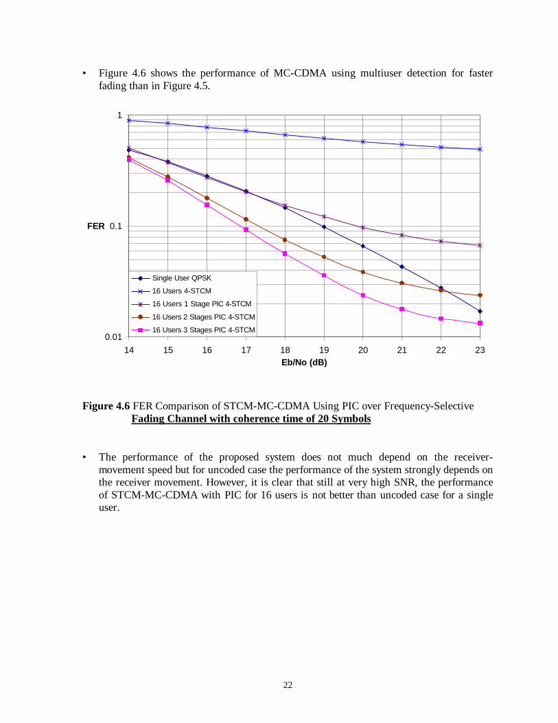
• Figure 4.6 shows the performance of MC-CDMA using multiuser detection for fasterfading than in Figure 4.5.
Figure 4.6 FER Comparison of STCM-MC-CDMA Using PIC over Frequency-SelectiveFading Channel with coherence time of 20 Symbols
• The performance of the proposed system does not much depend on the receiver-movement speed but for uncoded case the performance of the system strongly depends onthe receiver movement. However, it is clear that still at very high SNR, the performanceof STCM-MC-CDMA with PIC for 16 users is not better than uncoded case for a singleuser.
0.01
0.1
1
14 15 16 17 18 19 20 21 22 23Eb/No (dB)
FER
Single User QPSK
16 Users 4-STCM
16 Users 1 Stage PIC 4-STCM
16 Users 2 Stages PIC 4-STCM
16 Users 3 Stages PIC 4-STCM
23
• Figure 4.7 shows the performance of the proposed system when PIC is employed for 4, 8and 16 users over slow frequency-selective fading channel.
Figure 4.7 FER Performance Comparison of MC-CDMA Using 4-STCM with and withoutPIC over Multipath Fading Channel with coherence time of 20 Symbols
• The performance of 4 and 8 users can be improved closely to single user case. For 4users, use of PIC can obtain 1 dB gain at 0.0013 FER compared to no PIC. For 8 users,use of PIC can reach 4 dB gain at 0.013 FER compared to no PIC. For 16 users, asignificant gain can be achieved compared to no PIC. However, there is obviously a floorin 16 users curve while there is no floor in others cases.
• As the performance of the proposed system over the longer coherence time is alwaysbetter than the shorter one, we do not include the simulation result with the sameparameters over the longer coherence time channel.
0.0001
0.001
0.01
0.1
1
14 15 16 17 18 19 20 21 22 23Eb/No (dB)
FER
Single User 4-STCM
4 Users 4-STCM
8 Users 4-STCM
16 Users 4-STCM
4 Users 4-STCM Using PIC
8 Users 4-STCM Using PIC
16 Users 4-STCM Using PIC
24
• Figure 4.8 shows the performance comparison of sensitivity of the proposed system andMC-CDMA using TCM over multipath channel with both 20 symbols (Fast in the Figure4.8) and 20 frames (Slow in the Figure 4.8) coherence time.
Figure 4.8 FER-Performance Sensitivity Comparison of Number of Users of MC-CDMAUsing 4-STCM and TCM over Multipath Fading Channel with Different Valuesof coherence time
• For TCM (Schlegel and Costello, 1989), the performance is less sensitive to the numberof users but more sensitive to the receiver movement. There is more than 2 dBdegradation in SNR at 0.002 FER when compared the movements of the receiver butthere is only a little bit degradation of FER performance with 8 users compared to singleuser are in the system.
• For 4-STCM, the performance is more sensitive to the number of users as no combiningtechnique can be used but less sensitive to the receiver movement. There is no more than0.5 dB degradation in SNR for all cases of FER when compared the movements of thereceiver. However, there is about 4 dB degradation in FER performance when there are 8users in the system compared to single user case.
0.0001
0.001
0.01
0.1
1
14 15 16 17 18 19 20 21 22 23Eb/No
FERSlow TCM 1 User
Fast TCM 1 User
Slow TCM 8 Users
Fast TCM 8 Users
Slow 4-STCM 1 User
Fast 4-STCM 1 User
Slow 4-STCM 4 Users
Fast 4-STCM 4 Users
Slow 4-STCM 8 Users
Fast 4-STCM 8 Users
25
Conclusions
• The FER performance of the proposed system is much dependent on the multiple accessscheme due to the need of a combining technique. As no combining scheme can be used,the performance of the system is severely degraded even only one active user is in thesystem and much more weak due to MAI whenever more than four active users are in thesystem. This is confirmed from the FER comparison in the single user cases with andwithout MC-CDMA.
• There is no gain when using STCM compared to uncoded case over AWGN channel.Eventually, the performance of 2-STCM is also better than 4-STCM. As STCM holdingthe concept of diversity has designed for fading channel, TCM in the simulation showsthe best performance over AWGN channel.
• When considering the receiver movement, the performance of the proposed system for allcases of number of users are not much different compared to TCM and uncoded cases. InSTCM, the performance for all numbers of users degrades when the receiver movesfaster. These trends are the same as in uncoded cases. The performance for all uncodedcases are weaker than STCM when the receiver moves faster. Surprisingly, when usingTCM as an encoder, the performances are different when the receiver moves faster. TCMshows a better performance for less coherence time.
• If delay, weight and power consumption are negligible at the receiver, multiuser detectionor interference cancellation can be introduced. Based on the simulation results, multiuserdetection can significantly improve the performance of the proposed system. Considring16 active users, a gain of more than 10 dB SNR at 0.5 FER can be achieved whencomparing MC-CDMA using 1 stage PIC 4-STCM with MC-CDMA no PIC 4-STCM.
• In a real environment, the proposed system with increased the processing gain andmultiuser detection can be considered as a possible scheme for data transmission due tothe robustness over various Doppler shifts in practical channels of interest.
26
APPENDIX D
CONSTRUCTION OF SPACE-TIME CODED MODULATION
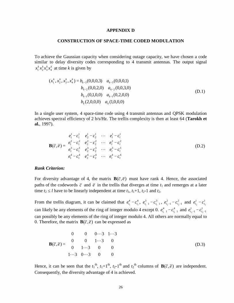
To achieve the Gaussian capacity when considering outage capacity, we have chosen a codesimilar to delay diversity codes corresponding to 4 transmit antennas. The output signal
In a single user system, 4 space-time code using 4 transmit antennas and QPSK modulationachieves spectral efficiency of 2 b/s/Hz. The trellis complexity is then at least 64 (Tarokh etal., 1997).
−−−−−−−−−−−−
=
4442
42
41
41
3332
32
31
31
2222
22
21
21
1112
12
11
11
),(
ll
ll
ll
ll
cececececececececececece
ec
LLLL
B (D.2)
Rank Criterion:
For diversity advantage of 4, the matrix ),( ecB must have rank 4. Hence, the associatedpaths of the codewords c and e in the trellis that diverges at time t1 and remerges at a latertime t2 ≤ l have to be linearly independent at time t1, t1+1, t2-1 and t2.
From the trellis diagram, it can be claimed that 4411 tt ce − , 3
13
1 11 ++ − tt ce , 21
21 22 −− − tt ce and 11
22 tt ce −can likely be any elements of the ring of integer modulo 4 except 0. 4
14
1 11 ++ − tt ce and 11
11 22 −− − tt ce
can possibly be any elements of the ring of integer modulo 4. All others are normally equal to0. Therefore, the matrix ),( ecB can be expressed as
=
0030310031003100
313000
),(
LLL
LLL
ecB (D.3)
Hence, it can be seen that the t1th, t1+1th, t2-1th and t2th columns of ),( ecB are independent.Consequently, the diversity advantage of 4 is achieved.
27
Determinant Criterion:
For coding advantage, we need to find codewords c and e such that
−−−−−−−−∑
=
l
kkkkkkkkkkkkkkkkk cececececececece
1
44332211*44332211 ),,,(),,,(det (D.4)
is minimized.
Referring that the codes are QPSK, then the codes is geometrically uniform. We can assumethat c is all zero codewords. We can place the edge label (x1, x2, x3 and x4) by complex formsinto equation above and replace each element to be
kkkk
kkkk
kkkk
kkkk
dsqoscpnqpbmonma
***
**
*
(D.5)
At time t1, t1+1, t2-1 and t2, the matrices are respectively contributed as follows
000000000000000
,
000000000000
,
0000
00000000
,
000000000000000 0
0*0
00
0*0
00
0
abmma
dssc
d
(D.6)
Finally, the determinant can be written as
+
∑=
3
1***
**
*
0
0
0
0
000000000000
detk
kkkk
kkkk
kkkk
kkkk
dsqoscpnqpbmonma
dc
ba
(D.7)
where a0 = b0 = c0 = d0 = 2ak, bk, ck and dk ≥ 0 , mk⋅pk⋅sk⋅ *