46
Rev 2.6 Multi- function Lathe Assistant

Rev 2.6
Multi-function
Lathe Assistant
- 1 -
Table of CONTENTS TABLE OF CONTENTS............................................................................................................................. 1
OVERVIEW ................................................................................................................................................. 4 APPLICABLE MODELS: .................................................................................................................................4 MANUALS REFERENCED: ..............................................................................................................................4 CORRECTIONS, ADDITIONS, AND IMPROVEMENTS:.......................................................................................4
A) AXIS LAYOUT ....................................................................................................................................... 5 MULTUS: ......................................................................................................................................................5 MACTURN 250/350: .....................................................................................................................................6 MACTURN 550: ............................................................................................................................................7
B) TURRET OPERATION ......................................................................................................................... 8 UPPER TURRET (A): .....................................................................................................................................8
Turret Index Assignment: ......................................................................................................................8 Turret Angle: B-Axis Angle Range: ......................................................................................................8 Turret Indexing Commands:..................................................................................................................9 B-Axis Positioning:.................................................................................................................................9 Tool Life Command: ............................................................................................................................10 L-Tool Indexing Function (Standard):................................................................................................10 Lathe Tool Index Function (Option): ..................................................................................................10 Tooling Data: ........................................................................................................................................11 Identifiers:.............................................................................................................................................11 Zero-Set: ...............................................................................................................................................11 Tool Touch-off:.....................................................................................................................................12 Calibration of Touch setter: .................................................................................................................12 Use of Touch setter:..............................................................................................................................12 Tool Offset Pages: ................................................................................................................................12 Coolant/Air Control:.............................................................................................................................13 Chip Removal Cycle before ATC Operation:.......................................................................................13
LOWER TURRET (B TURRET): .....................................................................................................................14 Notes: ....................................................................................................................................................14
SIMULTANEOUS 4-AXIS CUTTING: .............................................................................................................14 G/M-Codes: ...........................................................................................................................................14 Programming Tips:...............................................................................................................................14 Conditions:............................................................................................................................................15 Notes: ....................................................................................................................................................15 Program Examples: ..............................................................................................................................15
C) ATC/TOOLING OPERATIONS......................................................................................................... 16 ATC/TURRET COMMANDS:........................................................................................................................16
M-codes .................................................................................................................................................16 Parameters ............................................................................................................................................16 Tool commands.....................................................................................................................................17 Sub-Magazine commands ....................................................................................................................17 Program Example: ...............................................................................................................................17 ATC Operation Sequence:....................................................................................................................18 Manual Tool Change Procedure: ........................................................................................................18
D) C-AXIS OPERATION.......................................................................................................................... 19
- 2 -
G/M-CODES: ..............................................................................................................................................19 ADDRESS CHARACTERS: ............................................................................................................................19 CONDITIONS:..............................................................................................................................................19 NOTES: .......................................................................................................................................................19 PROGRAM EXAMPLE: .................................................................................................................................20 CALCULATING C-AXIS FEEDRATE: .............................................................................................................21
E) Y-AXIS OPERATION .......................................................................................................................... 21 G/M-CODES: ..............................................................................................................................................21 NOTES: .......................................................................................................................................................21 PROGRAM EXAMPLE: .................................................................................................................................21
F) B-AXIS (SLANT MACHINING) OPERATION ................................................................................ 22 G/M-CODES: ..............................................................................................................................................22 ADDRESS CHARACTERS: ............................................................................................................................23 CONDITIONS:..............................................................................................................................................23 NOTES: .......................................................................................................................................................23 PROGRAM EXAMPLE: .................................................................................................................................24
G) W-AXIS (SUB-SPINDLE) OPERATION........................................................................................... 26 G/M-CODES: ..............................................................................................................................................27 CONDITIONS:..............................................................................................................................................27 PARAMETERS: ............................................................................................................................................27 NOTES: .......................................................................................................................................................27 PART TRANSFER:........................................................................................................................................27 PROGRAM EXAMPLE (CHUCKING – USING TORQUE SKIP; METRIC):..........................................................28 PROGRAM EXAMPLE (CUT-OFF – USING TORQUE SKIP):............................................................................28 PROGRAM EXAMPLE (BARSTOCK – NO TORQUE SKIP): .......................ERROR! BOOKMARK NOT DEFINED. PROGRAM EXAMPLE (BARSTOCK ON LT; DOUBLE PULL OF SHAFT PART – NO TORQUE SKIP): .................29
H) COLLISION AVOIDANCE SYSTEM (CAS).................................................................................... 29 G/M-CODES: ..............................................................................................................................................29 NOTES: .......................................................................................................................................................29
I) NC TAILSTOCK (MULTUS B-300/400) ............................................................................................. 30 POSITION DESCRIPTIONS (SEE FIGURE 1): ..................................................................................................30 MANUAL MODE & SETUP: .........................................................................................................................30 G/M-CODES: ..............................................................................................................................................31 CONDITIONS:..............................................................................................................................................31 PARAMETERS: ............................................................................................................................................31 ADDRESS CHARACTERS: ............................................................................................................................32 NOTES: .......................................................................................................................................................32 PROGRAM EXAMPLE: .................................................................................................................................32
APPENDIX I............................................................................................................................................... 33 GENERAL NOTES: E-CONTROL AND NEWER ...............................................................................................33
APPENDIX II ............................................................................................................................................. 34 MACHINE SET-UP .......................................................................................................................................34
Machine Checks ...................................................................................................................................34 Macturn Parameters.............................................................................................................................34
APPENDIX III............................................................................................................................................ 36 COOLANT ...................................................................................................................................................36
Coolant Motor Electrical Connections ................................................................................................36 Coolant Alarms:....................................................................................................................................36

- 3 -
APPENDIX IV............................................................................................................................................ 37 INTERFERENCE AWARENESS ZONES...........................................................................................................37
APPENDIX V ............................................................................................................................................. 38 CYCLE TIME REDUCTION ...........................................................................................................................38
Track the time .......................................................................................................................................38 Turret one direction enable ..................................................................................................................38 High speed M110 command .................................................................................................................38 M153: M-tool Spindle Interlock Off ....................................................................................................38 Home Position instead of Limits. .........................................................................................................39
APPENDIX VI............................................................................................................................................ 40 PROGRAM EXAMPLES REFERENCE DRAWING ............................................................................................40
APPENDIX VII .......................................................................................................................................... 41 MACTURN PUBLICATIONS ..........................................................................................................................41
Okuma Manuals ...................................................................................................................................41 Service Publications .............................................................................................................................41 Applications Engineering Publications ...............................................................................................41
APPENDIX VIII......................................................................................................................................... 42 ATC OPERATION SEQUENCE:.....................................................................................................................42
INDEX ......................................................................................................................................................... 44
- 4 -
Overview This is a reference document compiling and condensing information from manuals related to Multi-Function Lathes. Not all functions apply to all machine models. Consult the proper manuals for more information.
Applicable Models: Macturn- 30, 50, 250, 350, 550 Multus- 300, 400
Manuals referenced: 5262 P200- Macturn/Multus operation 5097 P100- Macturn Operation 5005 E100- Sub magazine spec With changes in control versions, functions that were described in separate manuals may be included in a newer Macturn/Multus operation manual.
Corrections, Additions, and Improvements: While every effort has been made to assure that this document is accurate please be alert for any errors that may be found. Also, software and hardware changes could render some information obsolete while machines using older software may not be able to take advantage of some commands listed in this document. For software updates please contact the Okuma Software Department.
If any errors or omissions are found, or if the reader feels that something is not clearly explained please contact David Fischer in the Okuma Applications Engineering department concerning these issues. They will be reviewed and dealt with appropriately.

- 5 -
A) Axis Layout
Multus:
- 6 -
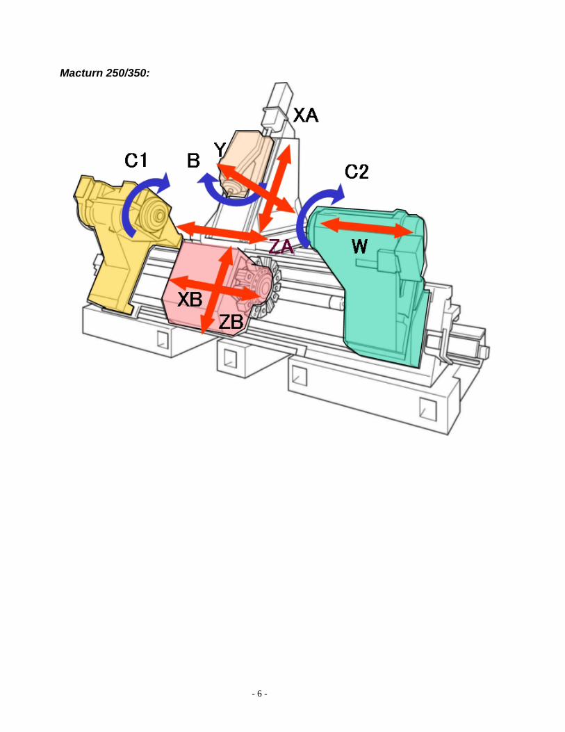
Macturn 250/350:
- 7 -
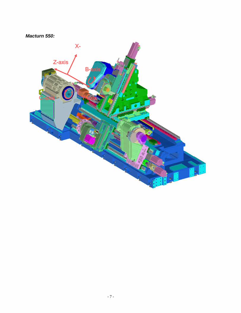
Macturn 550:
X-
Z-axis
Y-axis
B-axis
C-axis
- 8 -
B) Turret Operation
Upper Turret (A):
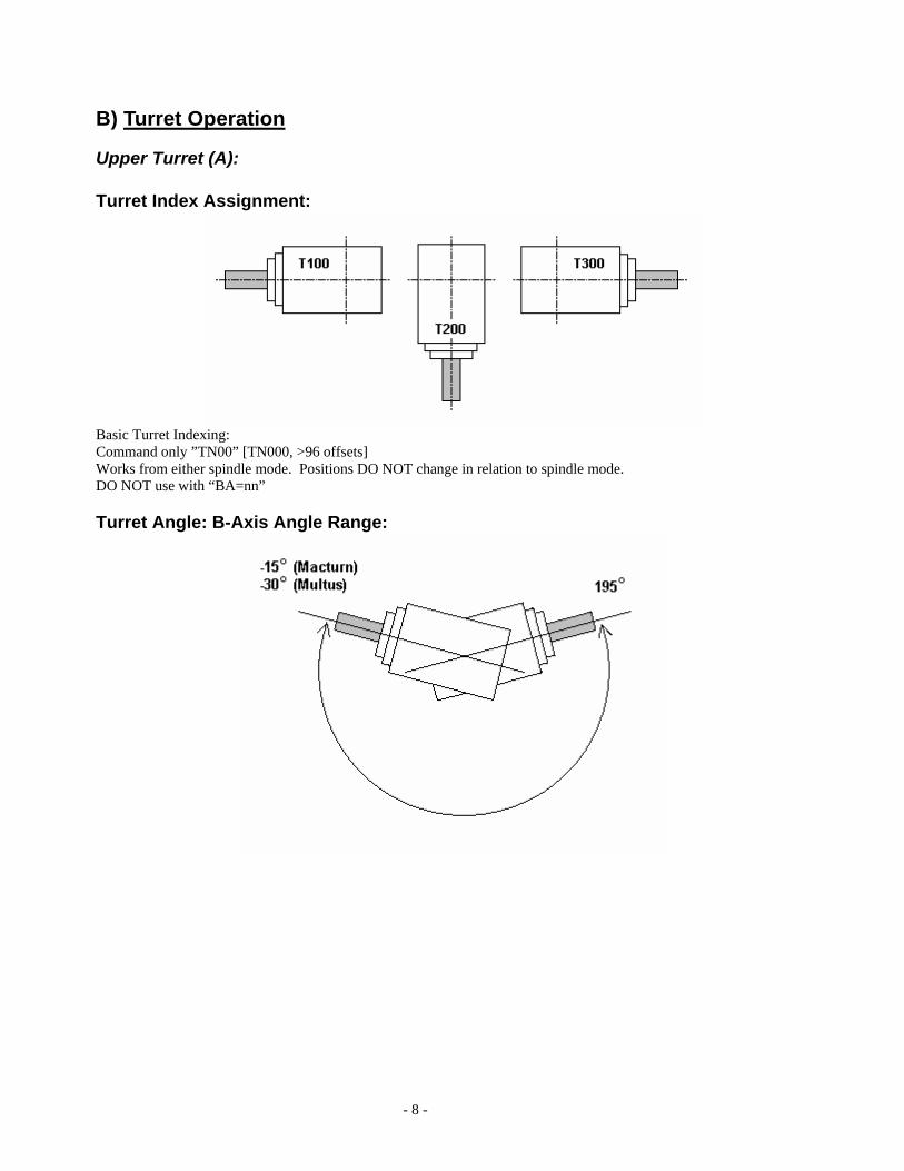
Turret Index Assignment:
Basic Turret Indexing: Command only ”TN00” [TN000, >96 offsets] Works from either spindle mode. Positions DO NOT change in relation to spindle mode. DO NOT use with “BA=nn”
Turret Angle: B-Axis Angle Range:
- 9 -
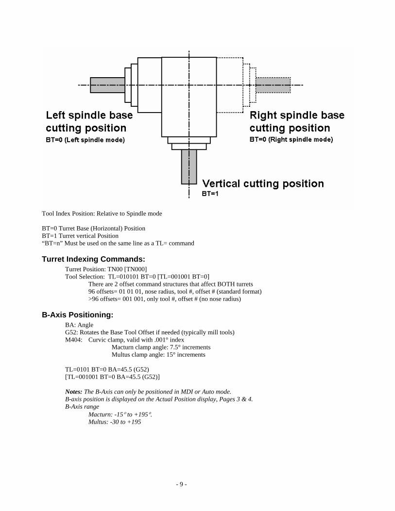
Tool Index Position: Relative to Spindle mode
BT=0 Turret Base (Horizontal) Position BT=1 Turret vertical Position “BT=n” Must be used on the same line as a TL= command
Turret Indexing Commands: Turret Position: TN00 [TN000] Tool Selection: TL=010101 BT=0 [TL=001001 BT=0]
There are 2 offset command structures that affect BOTH turrets 96 offsets= 01 01 01, nose radius, tool #, offset # (standard format) >96 offsets= 001 001, only tool #, offset # (no nose radius)
B-Axis Positioning: BA: Angle G52: Rotates the Base Tool Offset if needed (typically mill tools) M404: Curvic clamp, valid with .001° index
Macturn clamp angle: 7.5° increments Multus clamp angle: 15° increments TL=0101 BT=0 BA=45.5 (G52) [TL=001001 BT=0 BA=45.5 (G52)]
Notes: The B-Axis can only be positioned in MDI or Auto mode. B-axis position is displayed on the Actual Position display, Pages 3 & 4. B-Axis range
Macturn: -15° to +195°. Multus: -30 to +195
- 10 -
Tool Life Command: To use tool life commands, replace the TL= with TG= OG= TL=010101 BT=0 BA=45.5 G52 [TL=001001 BT=0 BA=45.5 G52] TG=1 OG=1 BT=0 BA=45.5 G52 (same for >96 offsets)
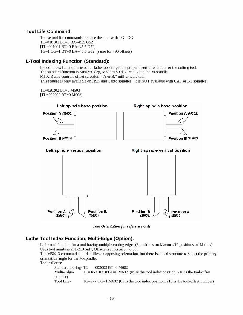
L-Tool Indexing Function (Standard): L-Tool index function is used for lathe tools to get the proper insert orientation for the cutting tool. The standard function is M602=0 deg, M603=180 deg. relative to the M-spindle M602-3 also controls offset selection- “A or B,” mill or lathe tool This feature is only available on HSK and Capto spindles. It is NOT available with CAT or BT spindles. TL=020202 BT=0 M603 [TL=002002 BT=0 M603]
Tool Orientation for reference only
Lathe Tool Index Function; Multi-Edge (Option): Lathe tool function for a tool having multiple cutting edges (8 positions on Macturn/12 positions on Multus) Uses tool numbers 201-210 only, Offsets are increased to 500 The M602-3 command still identifies an opposing orientation, but there is added structure to select the primary orientation angle for the M-spindle. Tool callouts:
Standard tooling- TL= 002002 BT=0 M602 Multi-Edge- TL= 05210210 BT=0 M602 (05 is the tool index position, 210 is the tool/offset number) Tool Life- TG=277 OG=1 M602 (05 is the tool index position, 210 is the tool/offset number)
- 11 -
Tool number (TG) is a calculated value ranging from 201 to 280 (8 index; Macturn) or 320 (12 index; Multus). TG= 200 + [[tool number – 201] x 8] + Edge number (Macturn formula) TG= 200 + [[tool number – 201] x 12] + Edge number (Multus formula) Note: When a new position is commanded it becomes the new “A” position (M602) and the new “B” position (M603) is 180° from it. This is reset by the “TC=” command or a tool change.
Tooling Data: Tools/offsets range from 1 to 96 (1 to 200 tools and 500 offsets optional). A mill defined tool CAN be used as a Lathe tool, but a Lathe defined tool CANNOT be used as a Mill tool. Ex. A drill used for side drilling can also be used with the M602/3 to lock the tool and drill on center as a lathe tool with the part rotating. Tool Management Data:
• Tool Number, Tool Kind, Tool Size/Weight • Sub Mg. Tool check box - Check if tool is a main magazine tool, leave unchecked if the tool is a sub-
magazine tool. (Note: There will not be a “Sub Mg. Tool” check box on machines not equipped with a sub-magazine.)
Identifiers: Tool Kind L Lathe tool M Mill tool S Sensor DT Dummy tool Assigned by control D Dummy Pot (Large Tool) R Reserved Pot (Large Tool, See note below) Tool Size/Weight
Standard Standard tool; Stored in ATC pot #n. Other tools can be stored in both right and left pots (magazine #n+1 & #n-1).
B Large diameter tool left; Stored in ATC pot #n. No tool can be stored in the left pot (magazine #n+1).
BR Large diameter tool right; Stored in ATC pot #n. No tool can be stored in the right pot (magazine #n-1).
E Large diameter tool; Stored in ATC pot #n. Only standard tools can be stored in the right and left pots (magazine #n+1 & #n-1).
H Heavy Tool; ATC arm acceleration/deceleration is reduced. SL Super large diameter tool; Stored in ATC pot #n. No tool can be stored in
either right or left pot (magazine #n+1 or #n-1).
Note 1: When a super large, L-large or R-large diameter tool is removed from the magazine pot and mounted in the turret, the pot where the tool was stored is recognized as a reserved pot and marked with an "R" identifier. Note 2: When a tool is defined as a large tool of any kind the ATC arm acceleration/deceleration is reduced. The speed of the ATC arm is unchanged.
Zero-Set: Zero set on the upper turret should always be set from the spindle face of the turret, never from a zero-tool as is typically done on a lathe. This is so that when the turret is rotated to different angles the tool tip position can be correctly calculated.

- 12 -
Tool Touch-off: Even though the Macturn can have 4 sets of offsets in each spindle mode it is a simple matter to touch off each tool through the use of Auto Calc.
• Set Zero as stated above. • Place the turret in the Base A or Base B position. Select the one that makes it easier to touch off. • Select the offset page that matches the tool position. • Touch off in Z and X (Z only for M-tools). • Calc the tool offset for both X and Z. • Press Auto Calc to set the correct data in all other offsets.
Note: Auto Calc should only be used when tools have been touched off with the turret in the Base or Vertical position.
Calibration of Touch setter: • Load a qualified tool in the spindle. • Select the position (A or B) that allows the easiest access to the touch setter. • Make sure the left spindle (G140) is selected. • While in Manual Mode, select “Parameters” and advance the touch setter arm. The “Touch setter
(Sensor Position)” page should be displayed. • Move the tool into position. • Using the touch setter buttons touch off the tool in X and Z. • Repeat for all four sides of the touch setter.
Note 1: In order to calibrate the touch setter it is necessary to have a properly qualified tool. This can be obtained by touching a tool off on a part or by using a tool pre-setter. The accuracy of this measured tool will directly affect the accuracy of the touch setter. Note 2: To calibrate all four sides of the touch setter will require having qualified tool(s) that can reach all four sides of the sensor head while the turret is in the Base (BT=0) position. Note 3: The touch setter should only be calibrated in the base (horizontal) position.
Use of Touch setter: The Touch-setter makes tool setup extremely easy. Once the touch setter is calibrated: • Rotate the tool to a position that makes it easy to touch-off the tool (M602/M603). • Advance the touch setter. • Touch off M-tools in Z. Touch off L-tools in X & Z (The screen will automatically change to the correct turret cutting position). All offsets will be calculated for both left and right spindles.
Tool Offset Pages: Main Spindle (G140) Sub spindle (G141) Base (Horizontal)
(BT=0) Vertical (BT=1)
Base (Horizontal) (BT=0)
Vertical (BT=1)
Offset Number
Position-A (M602)
Position-B (M603)
Position-A (M602)
Position-B (M603)
Position-A (M602)
Position-B (M603)
Position-A (M602)
Position-B (M603)
Base A Base B Vert A Vert B Base A Base B Vert A Vert B 1 2 … …
- 13 -
96 Note: for 45° lathe tools: When using lathe tools at an angle (typically 45°) the touchsetter or Auto Calc will give some unexpected results. This is because of how Auto Calc works. When Auto Calc calculates the other offsets from the one that was set it does so based on the distance of the tool edge back to the center point of the turret. As long as you are touching off a tool at either the base or vertical position this is not a problem. However, when toughing tools off at different angles (such as 45°) you will get unexpected results for the opposite lathe tool index position.
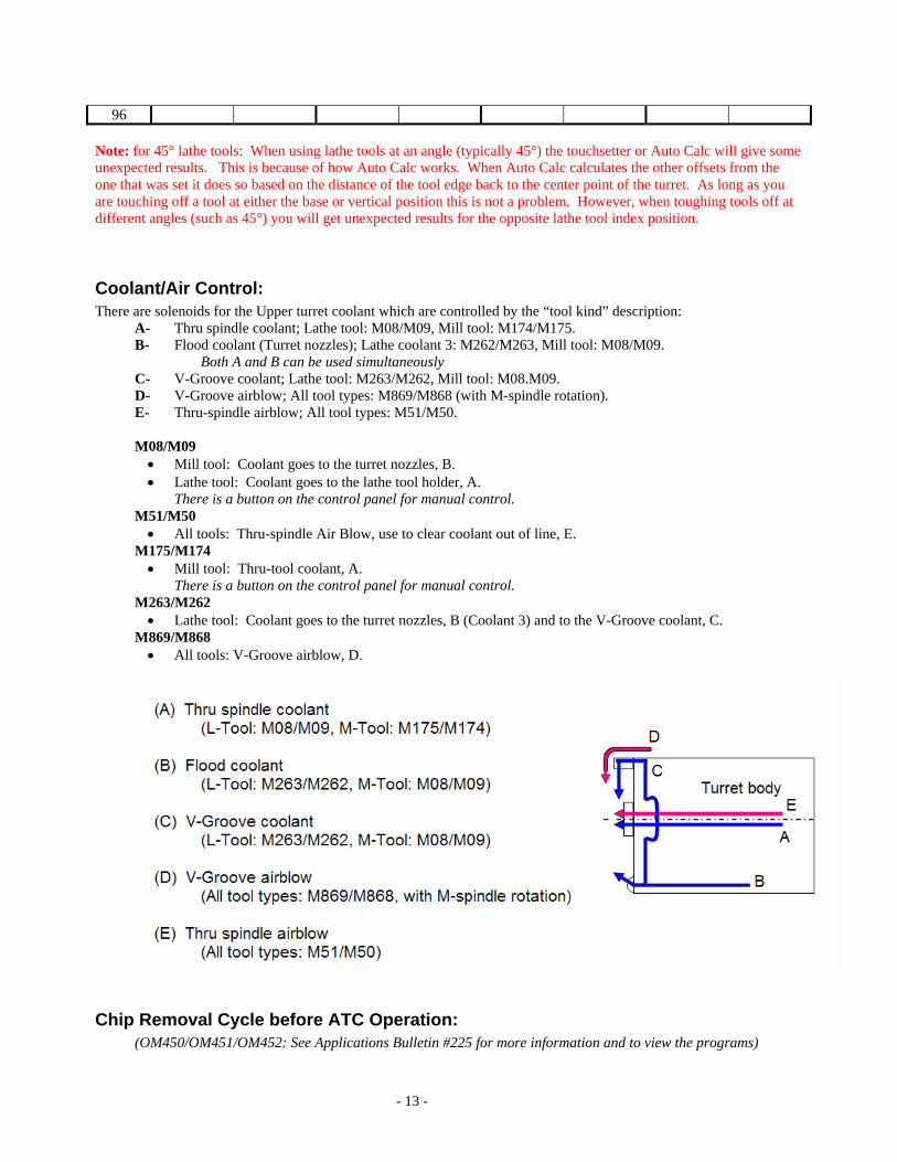
Coolant/Air Control: There are solenoids for the Upper turret coolant which are controlled by the “tool kind” description:
A- Thru spindle coolant; Lathe tool: M08/M09, Mill tool: M174/M175. B- Flood coolant (Turret nozzles); Lathe coolant 3: M262/M263, Mill tool: M08/M09.
Both A and B can be used simultaneously C- V-Groove coolant; Lathe tool: M263/M262, Mill tool: M08.M09. D- V-Groove airblow; All tool types: M869/M868 (with M-spindle rotation). E- Thru-spindle airblow; All tool types: M51/M50.
M08/M09 • Mill tool: Coolant goes to the turret nozzles, B. • Lathe tool: Coolant goes to the lathe tool holder, A.
There is a button on the control panel for manual control. M51/M50 • All tools: Thru-spindle Air Blow, use to clear coolant out of line, E.
M175/M174 • Mill tool: Thru-tool coolant, A.
There is a button on the control panel for manual control. M263/M262 • Lathe tool: Coolant goes to the turret nozzles, B (Coolant 3) and to the V-Groove coolant, C.
M869/M868 • All tools: V-Groove airblow, D.
Chip Removal Cycle before ATC Operation: (OM450/OM451/OM452: See Applications Bulletin #225 for more information and to view the programs)
- 14 -
• For turning tools, drills and other equipment likely to entangle chips around the tool, the provided chip removal
cycle should be used before the ATC cycle (M321 or M421). • The provided chip removal cycle takes about five seconds. • This chip removal cycle is controlled by a “LIB (library)” program, which permits the user to change the air blow
time and other parameters according to the workpiece material and chip condition. • For the MACTURN series type CAT and BT turning holder, which uses a tool locating pin, the removal cycle
cannot be used as it requires the rotation of the M-tool spindle. If this holder is instructed to perform the removal cycle, it will result in an alarm since it is internally interlocked to prevent the rotation of the M-tool spindle. Programs (.LIB) OM450 - spindle air blow, periphery coolant & spindle nose air blow (w/spindle rotating)
Purpose: To drain coolant from the spindle and remove chips around the tool OM451 - Periphery coolant and spindle nose air blow (with spindle rotating)
Purpose: To remove chips around the tool OM452 - Spindle nose air blow (with spindle rotating)
Purpose: To remove chips around the tool
Lower Turret (B turret):
Notes: The lower turret is available with M-function as an option. The lower turret may cause interference with the workholding (Main spindle; Macturn 250/350, Sub-spindle;
Macturn 550). (Ref. Appendix IV – Interference Awareness Zones)
Simultaneous 4-Axis Cutting:
G/M-Codes: G13 A-Turret select G14 B-Turret select G110 Constant speed cutting on turret A G111 Constant speed cutting on turret B G122 W-axis control, turret A designation G123 W-axis control, turret B designation M206 Turret Synchronous Feed Mode OFF M207 Turret Synchronous Feed Mode ON M200 Z-axis synchronized feeding cancel M201 Z-axis synchronized feeding G13 M202 Z-axis synchronized feeding G13
Programming Tips: • Determine the extent of operations to be performed by turrets A and B.
o The cutting times required for these two turrets should be well matched when determining the sections to be cut by each.
• Determine optimum cutting conditions. o Since a spindle change cannot be performed during a simultaneous 4-axis cut, the cutting speed
will vary according to the diameter being cut. Select the insert grade carefully to suit the workpiece material to be cut.
o Select feedrate and depth of cut by taking the cutting at the two turrets into account o Determine the cutting conditions so that a total of the cutting power required by the two turrets
will not exceed the capacity of the machine.
- 15 -
• Other considerations o The use of the INDIVIDUAL switch allows the turrets to be operated independently, facilitating
checking of trial cuts. o Care should be taken to avoid interference:
Interference between a boring bar and the chuck When performing end face cutting with the tools on turret A:
• Interference between tools on turret A and a boring bar on turret B, • Interference between tools on turret A and ID toolholder on turret B
o Program movements of the tools on turret B taking into account those of turret A. G02 and G03 should also be programmed taking cutting with the tools on turret A into account.
o In constant speed cutting mode operation called for by G96, G110 and G111 select the turret on which constant cutting speed is obtained: G96 G111 calls for constant speed cutting for turret B and G96; G110 cancels G96 G111 and selects constant speed cutting mode on turret A.
Note: This feature generates large differences in cutting speeds for the tools on turrets A and B when, for example, performing simultaneous cutting on a workpiece with large diameter differences. Therefore, the cutting portion handled by each turret and the cutting tip material should be selected very carefully.
Conditions: • The G code used to select the turret must always be placed at the start of a program.
Notes: • There are no differences in programming format between the programs for turrets A and B. • All commands in a program beginning with a turret selection G code are effective for the selected turret. • To program an operation for the other turret, specify the G code to select it. • Program execution proceeds in order from smaller to larger P code numbers. • S and M commands cannot be synchronized with the M100 command. • The same number of M100 codes must be used at both the G13 and the G14 sides in the program. If a
different number of M100 codes were to be programmed in the G13 and G14 sides, operation would continue with no waiting time.
• The insertion of an M100 command into a nose R compensation operation will result in an alarm. No advance program reading is conducted during a stop which has been programmed by an M100 command. The nose R compensation, however, requires advance program reading, and for this reason insertion of an M100 command in this operation is not permitted.
• Take special care not to mix P codes and the M100 command. Any attempt to stop one turret by use of an M100 command while the other turret is stopped due to a P code will result in operation continuing with no waiting time at all.
Program Examples: G13 G0 X500 Z500 X100 Z0 S1500 T010101 M42 M3 P10 (A) G1 X20 F3.5 G0 X90 G1 Z-25 P20 (B) X150 G0 X500 Z500 M5 P40 (D) G14 G0 X500 Z500 X24 Z4 S1500 T010101 M42 M3 P10 (A) G1 Z-50 F2.5 (Rough) P20 (B)
- 16 -
G0 X22 Z4 X25 G1 Z-50 F2 (Finish) P30 (C) G0 X22 Z4 X500 Z500 M5 P40 (D)
In the example program above, blocks A & B are executed for both G13 and G14 side programs. Blocks C and D are executed in order.
C) ATC/Tooling Operations
ATC/Turret Commands: M-codes M06 Tool Change command, moving tool from ready station to turret. This is part of the
M321/M421 tool change macro and, generally, should not be used by itself. M321/M421 Tool change macro, handles system checks to simplify program, includes M06
Opt. Parameter: Other Function, M-code macro type select- Select the preferred M-code by parameter. Effect= M321, No Effect= M421
M51/50 Thru M-spindle Air Blow On/Off M175/174 Thru M-spindle coolant On/Off, use with lathe or mill tool M277/M276 ATC Door open/close (Tool change command will shut the door.) M227 ATC operating completion wait command.(use at program stop M00/M01/M91) M228 Tool return command - Returns the prepared tool to the magazine. M229 CB=*** M-spindle orient, CB= Angle, absolute only M403/M404 B-Axis Unclamp/Clamp. Use at any 15º increment to clamp the B-Axis in position. (Ex.:
Use it when turning with a 45º tool holder.) M602 Index (rotate) lathe tool Position A, insert facing UP M603 Index (rotate) lathe tool Position B, insert facing DOWN M604/M605 One directional positioning enable off/on. Machine System Parameter (Turret/Door): One
directional positioning enable must be un-checked to enable these m-codes M814/M813 Modal command to allow upper turret tool change while lower turret is cutting. (Cycle time
reduction) M869/M868 M tool: Spindle nose air blow On/Off. Parameters VTF*A[ ] Tool offset; Base A; Left Spindle VTF*B[ ] Tool offset; Vertical A; Left Spindle VTF*C[ ] Tool offset; Base A; Right Spindle VTF*D[ ] Tool offset; Vertical A; Right Spindle VTF*E[ ] Tool offset; Base B; Left Spindle VTF*F[ ] Tool offset; Vertical B; Left Spindle VTF*G[ ] Tool offset; Base B; Right Spindle VTF*H[ ] Tool offset; Vertical B; Right Spindle VNR*A[ ] Tool Nose Radius; Base A; Left Spindle . . . (Same pattern as Tool Offsets) VNR*H[ ] Tool Nose Radius; Vertical B; Right Spindle VTW*A[ ] Tool Wear Offset; Base A; Left Spindle . . . (Same pattern as Tool Offsets) VTW*H[ ] Tool Wear Offset; Vertical B; Right Spindle VTTLN[*] Current tool in turret. (* The value in brackets should always be 1 when using an H1 turret.)
- 17 -
VTOF* Current active Tool Offset VTWO* Current active Tool Wear Offset * Axis (X, Y, or Z)
[ ] – Tool number
Tool commands TN00 [TN000] Turret index command, 3 positions TL=®®**∆∆ TL=***∆∆∆
Tool number/offset activate command. ®®: Tool nose radius compensation number. **: Tool number ∆∆: Tool offset number.
TG=** OG=* Tool Life function callout. TG= Tool group, OG= Offset group (1,2,3) OF= [*]** Allows changing of Tool Offsets without a ‘TL’ command, such as secondary offset needs.
[*]** = offset number BT=0/1 Rotate turret Horizontal or Vertical, Use with TL= command BA= ***.*** Rotate turret to specified angle, will use BT= for reference angle MT=[*]**01 Next tool preparation command. (*)** = tool number. 01 = turret pot number.
(*** - Three digits for optional 200 sets of tool data) MT=1 TG=** Next Tool prep. For Tool Life function MT=1 Prepares empty tool pocket, after tool change turret is empty MG=** Magazine Pot index command, **= pot num. (machine waits for command completion) TC= 1 Turret index, M-spindle orient to the ATC position command (T100 M602) G21 HP=* ATC position return command. 1 = tool change position for H1 turret. 4 = tool change
completion position. 6 = sub-magazine tool change position. (Note: On Multus only this requires the Y-mode to be active- G138)
oMGMI Mac-550 System I/O check ID for touchscreen interlock activation. (Use this example program to check the ATC magazine access door. If it is open the program will pause until it is closed. Without this code the machine will alarm out if the door is open.)
N1 IF[VORD[1339]EQ 1]N1 (If door interlock is locked, continue) M321 (this is I/O for Mac550, P200)
Sub-Magazine commands M652 Turns off Main magazine flag for all tools in Main mag. M820 Group Move to Main tool command MTM=** Move to Main: Moves tools from sub mag to main and sets flag to keep tools there after tool
changes. Must be at HP=6 to move tools (MG=14 to place pot 43 at the transfer position) MTM=0 TG=** Move to Main, Tool Life function, only moves one (active) tool MTS=** Move to Sub MGS=** Sub-mag Pot Index command i2MG1LK System I/O check ID for touchscreen interlock activation. (Use this example program to
check the ATC magazine access door. If it is open the program will pause until it is closed. Without this code the machine will alarm out if the door is open.)
N1 IF[VIRD[0304]EQ 1]N2(If door interlock is locked, continue) GOTO N1 (this is I/O for Mac250, field net) N2 M321
Program Example: MT=501[MT=1 TG=5] Pre-tool call [Pre-tool call for tool life function]
( Cutting Portion ) G0 X4 Z.5 M9 M174 Rapid clear of part, turn off coolants (even if not used) G0 X50 M51 Rapid to X-limit, turn on thru-spindle air purge G21 HP=4 Move to Home Position
- 18 -
TC=1 M50 Index turret, turn off air purge M321 Tool change macro MT=601 [MT=1 TG=6] Pre-tool call [Pre-tool call for tool life function]
ATC Operation Sequence: Multus B-300/400
MT command : S1 to S7 M6 command : S8 to S21 M228 command :S7 to S1
Macturn 250/350 standard magazine specification
MT command : S1 to S6 M6 command : S7 to S14 M228 command :S6 to S1
Macturn 550 standard magazine specification
MT command : S1 to S10 M6 command : S11 to S27 M228 command :S10 to S1
Manual Tool Change Procedure: 1. In Manual mode:
a. Open shutter door. 2. In MDI mode:
a. G138 (Multus only) b. G21 HP=4 c. TC=1 d. G21 HP=1 e. MT=**01 (** = Tool number)
3. In Manual mode: a. Press One-step Advance to cycle through the tool change sequence.
If the tool change arm needs to be moved in “Pulse-Handle” mode perform steps 1, 2 and 3 above to ATC step 10. 4. At step 10 (there are actually several parts to step 10) press one step forward until the arm moves to the spindle
and grips the tool. 5. Go to the “Axis Data” screen and press the Axis Change button until the EC axis is displayed. 6. Record the RAPA position. 7. Go to the System Check Mode screen. 8. Select item #4 “EC Pulse-Handle Mode.” 9. Move the ATC arm using the pulse handle. Monitor the RLOAD to make sure it is not excessive. 10. When finished return the arm to the original EC position. 11. Go to the System Check Mode screen and take the ATC arm out of Pulse-Handle mode. 12. One step forward or reverse to return to ATC step #1.
- 19 -
D) C-Axis Operation G/M-Codes:
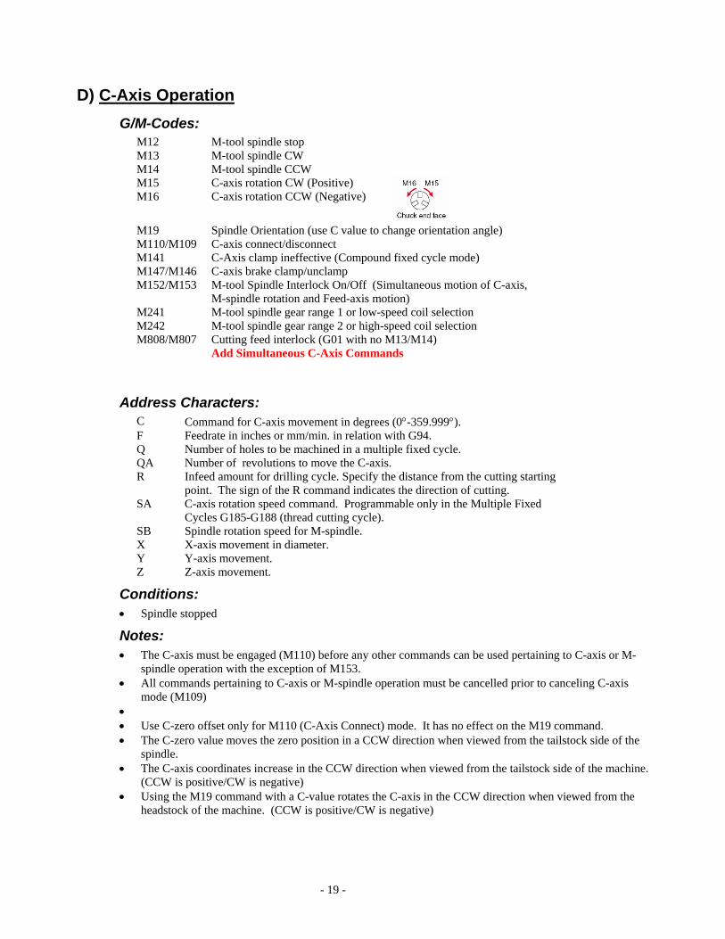
M12 M-tool spindle stop M13 M-tool spindle CW M14 M-tool spindle CCW M15 C-axis rotation CW (Positive) M16 C-axis rotation CCW (Negative)
M19 Spindle Orientation (use C value to change orientation angle) M110/M109 C-axis connect/disconnect M141 C-Axis clamp ineffective (Compound fixed cycle mode) M147/M146 C-axis brake clamp/unclamp M152/M153 M-tool Spindle Interlock On/Off (Simultaneous motion of C-axis,
M-spindle rotation and Feed-axis motion) M241 M-tool spindle gear range 1 or low-speed coil selection M242 M-tool spindle gear range 2 or high-speed coil selection M808/M807 Cutting feed interlock (G01 with no M13/M14) Add Simultaneous C-Axis Commands
Address Characters: C Command for C-axis movement in degrees (0°-359.999°). F Feedrate in inches or mm/min. in relation with G94. Q Number of holes to be machined in a multiple fixed cycle. QA Number of revolutions to move the C-axis. R Infeed amount for drilling cycle. Specify the distance from the cutting starting
point. The sign of the R command indicates the direction of cutting. SA C-axis rotation speed command. Programmable only in the Multiple Fixed
Cycles G185-G188 (thread cutting cycle). SB Spindle rotation speed for M-spindle. X X-axis movement in diameter. Y Y-axis movement. Z Z-axis movement.
Conditions: • Spindle stopped
Notes: • The C-axis must be engaged (M110) before any other commands can be used pertaining to C-axis or M-
spindle operation with the exception of M153. • All commands pertaining to C-axis or M-spindle operation must be cancelled prior to canceling C-axis
mode (M109) • • Use C-zero offset only for M110 (C-Axis Connect) mode. It has no effect on the M19 command. • The C-zero value moves the zero position in a CCW direction when viewed from the tailstock side of the
spindle. • The C-axis coordinates increase in the CCW direction when viewed from the tailstock side of the machine.
(CCW is positive/CW is negative) • Using the M19 command with a C-value rotates the C-axis in the CCW direction when viewed from the
headstock of the machine. (CCW is positive/CW is negative)
- 20 -
Program Example:
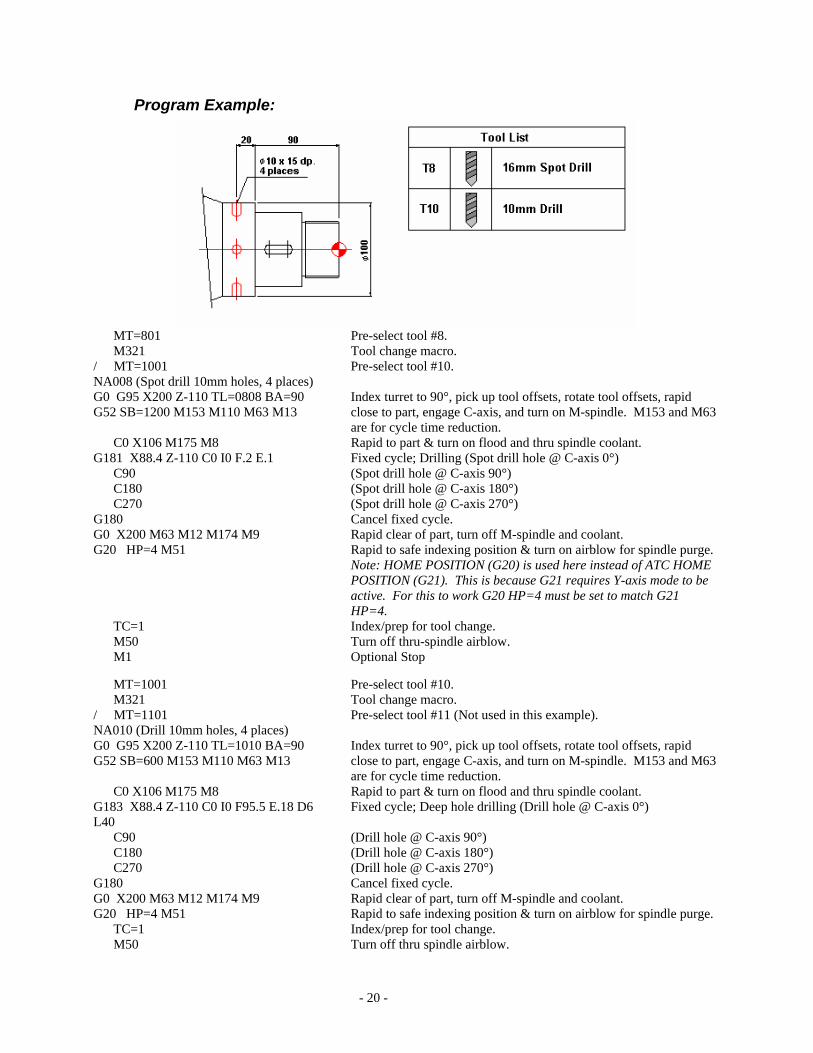
MT=801 Pre-select tool #8. M321 Tool change macro. / MT=1001 Pre-select tool #10. NA008 (Spot drill 10mm holes, 4 places) G0 G95 X200 Z-110 TL=0808 BA=90 G52 SB=1200 M153 M110 M63 M13
Index turret to 90°, pick up tool offsets, rotate tool offsets, rapid close to part, engage C-axis, and turn on M-spindle. M153 and M63 are for cycle time reduction.
C0 X106 M175 M8 Rapid to part & turn on flood and thru spindle coolant. G181 X88.4 Z-110 C0 I0 F.2 E.1 Fixed cycle; Drilling (Spot drill hole @ C-axis 0°) C90 (Spot drill hole @ C-axis 90°) C180 (Spot drill hole @ C-axis 180°) C270 (Spot drill hole @ C-axis 270°) G180 Cancel fixed cycle. G0 X200 M63 M12 M174 M9 Rapid clear of part, turn off M-spindle and coolant. G20 HP=4 M51 Rapid to safe indexing position & turn on airblow for spindle purge.
Note: HOME POSITION (G20) is used here instead of ATC HOME POSITION (G21). This is because G21 requires Y-axis mode to be active. For this to work G20 HP=4 must be set to match G21 HP=4.
TC=1 Index/prep for tool change. M50 Turn off thru-spindle airblow. M1 Optional Stop MT=1001 Pre-select tool #10. M321 Tool change macro. / MT=1101 Pre-select tool #11 (Not used in this example). NA010 (Drill 10mm holes, 4 places) G0 G95 X200 Z-110 TL=1010 BA=90 G52 SB=600 M153 M110 M63 M13
Index turret to 90°, pick up tool offsets, rotate tool offsets, rapid close to part, engage C-axis, and turn on M-spindle. M153 and M63 are for cycle time reduction.
C0 X106 M175 M8 Rapid to part & turn on flood and thru spindle coolant. G183 X88.4 Z-110 C0 I0 F95.5 E.18 D6 L40
Fixed cycle; Deep hole drilling (Drill hole @ C-axis 0°)
C90 (Drill hole @ C-axis 90°) C180 (Drill hole @ C-axis 180°) C270 (Drill hole @ C-axis 270°) G180 Cancel fixed cycle. G0 X200 M63 M12 M174 M9 Rapid clear of part, turn off M-spindle and coolant. G20 HP=4 M51 Rapid to safe indexing position & turn on airblow for spindle purge. TC=1 Index/prep for tool change. M50 Turn off thru spindle airblow.

- 21 -
M1
Calculating C-axis Feedrate: To accurately calculate the correct feedrate when using the C-axis use the following formula:
500 (metric) and 19.685 (inch) are constants. Fd: Desired linear feedrate (mm/min or in/min). Dia: Diameter of cutting. Metric: (Fd * 360 / (π * Dia)) / 360 * 500 Inch: (Fd * 360 / (π * Dia)) / 360 * 19.685
E) Y-Axis Operation G/M-Codes:
G138/G136 Y-axis connect/disconnect
Notes: • When the Y-axis is connected the X-axis is programmed in radius. • Y-axis mode remains in effect after NC Reset and power off. • Spindle mode cannot be changed in the Y-axis control mode. • During Y-axis control mode, the Y-axis mode button lamp lights on the option panel. • When the Y-axis control mode cancel command is received (G136) the NC automatically returns the
Y-axis to the turning position.
Program Example:
…. MT=0401 M321 / MT=1101 NA004 (Mill Pocket; 30mm End mill) G0 G94 X200 Z-283.8 TL=040404 BA=90 G52 SB=212 M241 M153 M110 M63 M16 M13
C180 X150 M8 G138 C180 G0 Y-44.751 G19 G1 X48.2 F5 M147 Y44.753 F10.6 Z-271.9 Y-44.751 Z-260 Y44.753 Z-248.1 Y-44.751 Z-236.2
- 22 -
Y44.753 G0 X73 Y.001 G1 X51.2 F53 X48.2 F5 G41 Y7.349 Z-221.2 F10.6 G3 Y.001 Z-220.2 J-7.348 K-26.5 G1 Y-60.751 Z-299.8 Y60.753 Z-220.2 Y.001 G3 Y-7.347 Z-221.2 K-27.5 G1 G40 Y.001 Z-236.2 G0 X73 M146 M63 M12 M9 X100 G136 G20 HP=4 M51 T100 M50 M1 MT=1101 M321 / MT=1401 NA011 (Drill; 10.5mm) G0 X200 Z-240 TL=1111 BA=90 G52 SB=606 M15 M63 M13
C180 X151 G138 C180 G0 Y-35 G183 X17.845 Y-35 Z-240 C180 I24.5 F90 E.19 D3 L21
Z-280 Y35 Z-240 G180 G0 X75.5 Y35 Z-240 M63 M12 M9 X100 G136 G20 HP=4 M51 T100 M50 M1 ….
F) B-Axis (Slant Machining) Operation G/M-Codes:
G126 Slant machining mode off G127 Slant machining mode on (B***.***) G174 Zero point shifting G175 Zero point shifting cancel
- 23 -
Address Characters: SX VZSHX (Shift X) SY VZSHY (Shift Y) SZ VZSHZ (Shift Z)
Conditions: • Y-axis mode in effect. • No LAP cycle in effect. • Coordinate conversion (G137) is not in effect. • Compound fixed cycle is not in effect.
Notes: • Slant machining mode is cancelled by <Reset>.
- 24 -
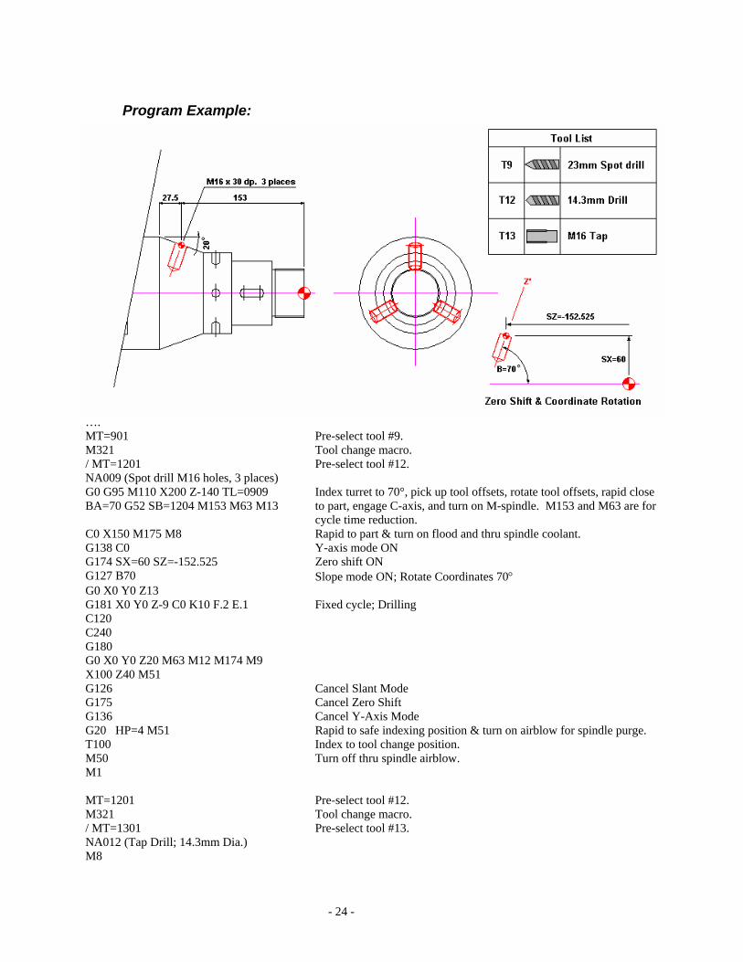
Program Example:
…. MT=901 Pre-select tool #9. M321 Tool change macro. / MT=1201 Pre-select tool #12. NA009 (Spot drill M16 holes, 3 places) G0 G95 M110 X200 Z-140 TL=0909 BA=70 G52 SB=1204 M153 M63 M13
Index turret to 70°, pick up tool offsets, rotate tool offsets, rapid close to part, engage C-axis, and turn on M-spindle. M153 and M63 are for cycle time reduction.
C0 X150 M175 M8 Rapid to part & turn on flood and thru spindle coolant. G138 C0 Y-axis mode ON G174 SX=60 SZ=-152.525 Zero shift ON G127 B70 Slope mode ON; Rotate Coordinates 70° G0 X0 Y0 Z13 G181 X0 Y0 Z-9 C0 K10 F.2 E.1 Fixed cycle; Drilling C120 C240 G180 G0 X0 Y0 Z20 M63 M12 M174 M9 X100 Z40 M51 G126 Cancel Slant Mode G175 Cancel Zero Shift G136 Cancel Y-Axis Mode G20 HP=4 M51 Rapid to safe indexing position & turn on airblow for spindle purge. T100 Index to tool change position. M50 Turn off thru spindle airblow. M1 MT=1201 Pre-select tool #12. M321 Tool change macro. / MT=1301 Pre-select tool #13. NA012 (Tap Drill; 14.3mm Dia.) M8
- 25 -
G0 G95 M110 X200 Z-140 TL=1212 BA=70 G52 SB=445 M153 M63 M13
C0 X150 M175 M8 G138 C0 Y-axis mode ON G174 SX=60 SZ=-152.525 Zero shift ON G127 B70 Slope mode ON; Rotate Coordinates 70° G0 X0 Y0 Z13 G183 X0 Y0 Z-42.296 C0 K10 F.2 E.27 D3 L28.6
C120 C240 G180 G0 X0 Y0 Z20 M63 M12 M174 M9 X100 Z40 M51 G126 Cancel Slant Mode G175 Cancel Zero Shift G136 Cancel Y-Axis Mode G20 HP=4 M51 Rapid to safe indexing position & turn on airblow for spindle purge. T100 Index to tool change position. M50 Turn off thru spindle airblow. M1 MT=1301 Pre-select tool #13. M321 Tool change macro. / MT=1401 Pre-select tool #14 (Not used in this example). NA013 (Tap; M16 x 2 - 3 Places) G0 G95 M110 X200 Z-140 TL=1313 BA=70 G52 SB=139 M153 M63 M13
C0 X150 M175 M8 G138 C0 Y-axis mode ON G174 SX=60 SZ=-152.525 Zero shift ON G127 B70 Slope mode ON; Rotate Coordinates 70° G0 X0 Y0 Z20 M175 M9 G178 X0 Y0 Z-36 C0 K10 F2 C120 C240 G180 G0 X0 Y0 Z20 M63 M12 M174 M9 X100 Z40 M51 G126 Cancel Slant Mode G175 Cancel Zero Shift G136 Cancel Y-Axis Mode G20 HP=4 M51 Rapid to safe indexing position & turn on airblow for spindle purge. T100 Index to tool change position. M50 Turn off thru spindle airblow. M1 ….

- 26 -
?) B-Axis (Contouring) Operation G/M-Codes:
G148/G149 B-Axis Mode OFF/ON
Address Characters:
Conditions: • Y
Notes: • S

- 27 -
G) W-Axis (Sub-Spindle) Operation G/M-Codes:
G22 G29/G28 Torque Skip ON/OFF. G140 Main spindle coordinate system. G141 Sub-spindle coordinate system. G122 W-axis control A-turret (default). G123 W-axis control B-turret, must be commanded on both turrets. G144/G145 W-axis function for LT-200. M77/M76 Parts catcher ADVANCE/RETRACT. M83/M84 Chuck CLAMP/UNCLAMP; Main spindle. M88/M89 Air blow ON/OFF; Main spindle. M151/M150 Synchronized rotation/orientation mode ON/CANCEL. M184/M185 Chuck open/close interlock release ON/OFF; Main spindle. M210 Ignore synchronized orientation of spindles. (Should be on the same line
as M151). M239 Opposing spindle orient M247/M246 Chuck open/close interlock release ON/OFF; Opposing spindle. M249/M248 Opposing spindle chuck OPEN/CLOSE. M289/M288 Opposing spindle air blow ON/OFF.
Conditions: When changing spindle modes always cancel spindle specific commands- (M110, G96, G138…)
Parameters: • Optional Parameter: 1st-2nd Spindle; 2nd Spindle Zero Offset - Use this to clock the right spindle to the left
if required. • Optional Parameter: 1st-2nd Spindle; Interference free distance ZB-W (Sub-spindle) - This parameter sets
the distance allowed between the sub-spindle and the lower turret.
Notes: • There is no PD Distance on the Macturn series. To limit the approach distance, use the W-axis soft limit.
This must be set for both the A and B turret. • When transferring a part between spindles and no value is placed in the C-zero offset of the 1st spindle or
Op. Par.: 1st-2nd Spindle; 2nd Spindle Zero Offset, the zero point on the part should be the same on both spindles.
• If a value is placed in Op. Par.: 1st-2nd Spindle; 2nd Spindle Zero Offset (assuming a left to right process), place 360 minus that parameter value in the right spindle C-zero offset to synchronize the spindle zero to the part zero.
Part Transfer: • On sub-spindle machines parts can be transferred with both spindles running or with both spindles
stopped. If the work piece requires a specific orientation between spindles this can be maintained as well. If no orientation is required, M210 can be used to reduce the cycle time required for pick-off.
- 28 -
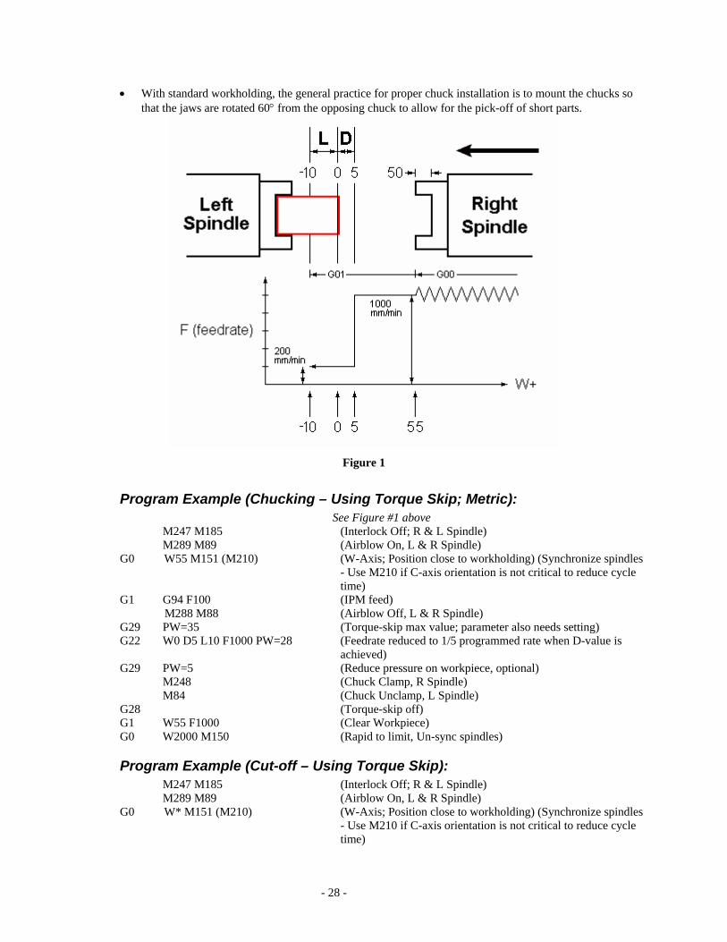
• With standard workholding, the general practice for proper chuck installation is to mount the chucks so that the jaws are rotated 60° from the opposing chuck to allow for the pick-off of short parts.
Figure 1
Program Example (Chucking – Using Torque Skip; Metric): See Figure #1 above
M247 M185 (Interlock Off; R & L Spindle) M289 M89 (Airblow On, L & R Spindle)
G0 W55 M151 (M210) (W-Axis; Position close to workholding) (Synchronize spindles - Use M210 if C-axis orientation is not critical to reduce cycle time)
G1 G94 F100 (IPM feed) M288 M88 (Airblow Off, L & R Spindle) G29 PW=35 (Torque-skip max value; parameter also needs setting) G22 W0 D5 L10 F1000 PW=28 (Feedrate reduced to 1/5 programmed rate when D-value is
achieved) G29 PW=5 (Reduce pressure on workpiece, optional)
M248 (Chuck Clamp, R Spindle) M84 (Chuck Unclamp, L Spindle)
G28 (Torque-skip off) G1 W55 F1000 (Clear Workpiece) G0 W2000 M150 (Rapid to limit, Un-sync spindles)
Program Example (Cut-off – Using Torque Skip): M247 M185 (Interlock Off; R & L Spindle) M289 M89 (Airblow On, L & R Spindle)
G0 W* M151 (M210) (W-Axis; Position close to workholding) (Synchronize spindles - Use M210 if C-axis orientation is not critical to reduce cycle time)
- 29 -
G1 G94 F100 (IPM feed) M288 M88 (Airblow Off, L & R Spindle) G29 PW=35 (Torque-skip max value; parameter also needs setting) G22 W0 D0.1 L0.15 F40 PW=28 (Feedrate reduced 1/5 when D-value achieved) G29 PW=5 (Reduce pressure on workpiece, optional)
M248 (Chuck Clamp, R Spindle) M84 (Chuck Unclamp, L Spindle)
G28 (Torque-skip off) (Pull part out in preparation for cut-off)* … (Cut-off part) G1 W5 F1000 (Clear Workpiece) G0 W2000 M150 (Rapid to limit, Un-sync spindles) *Note: Please be aware of interference conditions during the cut-off operation. It is recommended that prior to the cut-off operation the cut-off tool be placed in the spindle and the H1 turret should be rotated to the vertical position and moved close to the left spindle. When the part is pulled out it should be pulled out sufficiently to allow for cut-off stock and facing stock on the next part.
Program Example (Barstock on LT; Double Pull of shaft part – No Torque Skip): A Turret B Turret Notes (Transfer) (Transfer) G0 X20.0 Z0 T0200 G0 X20.0 Z=VNVLZ-VZOFZ+.1 T0500 Move A-Turret clear; Move B-
Turret to .1 from –Z-axis soft limit. P0100 P0100 Sync M247 M185 (Interlock Off; R & L Spindle) M289 M89 (Airblow On, L & R Spindle) M249 (Chuck Unclamp, R Spindle) G0 W=3.0 M151 (M210) (W-Axis; Position close to part
face) (Synchronize spindles - Use M210 if C-axis orientation is not critical to reduce cycle time)
G1 G94 F40 (IPM feed) M288 M88 (Airblow Off, L & R Spindle) G1 W0.0 F40 (Feed to position) M248 (Chuck Clamp, R Spindle) M84 (Chuck Unclamp, L Spindle) G1 W=2.5 1st pull M83 (Chuck Clamp, L Spindle) M249 (Chuck Unclamp, R Spindle) W0.0 (Feed to position) M248 (Chuck Clamp, R Spindle) M84 (Chuck Unclamp, L Spindle) G0 W50.0 M150 (Rapid to limit, Un-sync spindles) M246 M184 (Interlock on, R & L Spindle) P0110 P0110 Sync
H) Collision Avoidance System (CAS) G/M-Codes: G98/G99 Parameter #27=0/Parameter #27=1 (CAS ON/CAS OFF) M867/M866 Interference check cancel ON/OFF
Notes: Order of operations for setting up a job using CAS:
- 30 -
• Install workholding • Install cutting tools • Set Program Zero • Touch off all tools • Using the “Define Models” function:
Measure and define chuck. Measure and define chuck jaws. Measure and define workpiece blank.
• Using the “Register Models” function: Measure and define cutting tools. Measure and define toolholders.
• Using the “Define Models” function: Assemble cutting tools and toolholder
• If a tool gets stuck inside of a collision zone it is still possible to move the axis by pressing and
holding “Interlock Release” and then use the pulse handle or push buttons to move the tool clear. NOTE: an alarm message will appear on the screen stating that CAS is off.
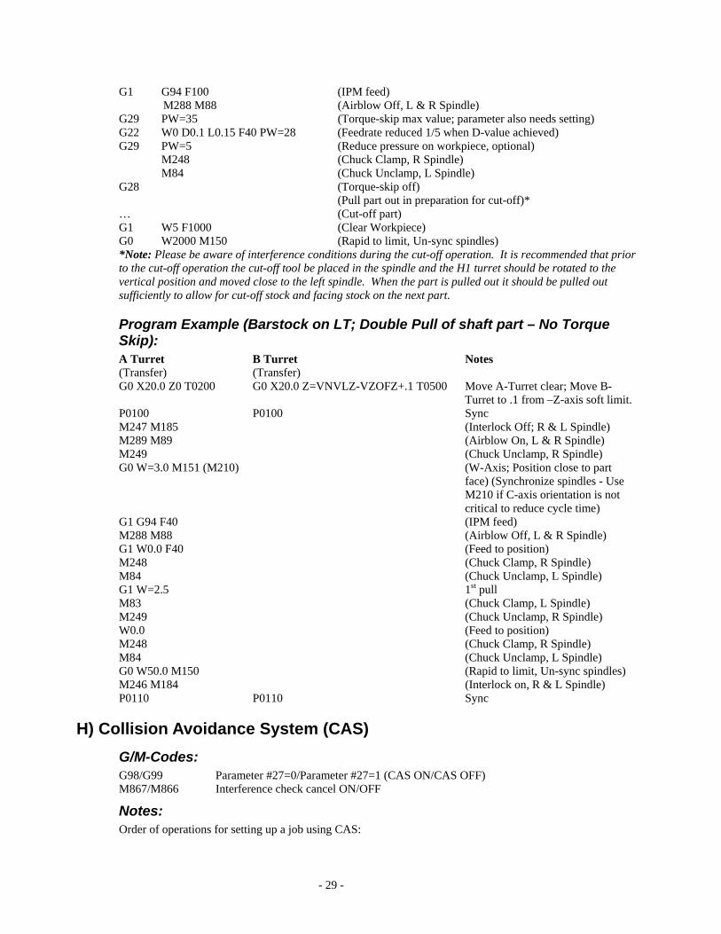
I) NC Tailstock (Multus B-300/400) The NC tailstock is a ballscrew driven, dead quill unit (Live quill optional) with a spring pack for thrust load. There is no quill travel similar to a hydraulic tailstock. Instead, the entire tailstock body moves. The tailstock is the W-Axis. W-Zero is used and it is recommended that it be set to where the tailstock engages the part. There are 10 sizing positions and the tailstock has tailstock confirmation built in.
Position Descriptions (see Figure 1): • Work Position: The position where the tailstock engages the part (M56). This should be the lowest of the
position settings. This position is in reference to the W-Axis Zero. • +/-OK: Tolerance for the Work Position. • Approach Position: When engaging the part the tailstock will rapid to this position and then feed to the
Work Position. When retracting from the part the tailstock will feed out to this position and then rapid the rest of the way. This position should be set to clear the part. This value must be greater than the Work Position. This position is used with both the foot pedal and M55/M56.
• Retract Position: The clearance position for loading/unloading parts (M55). This value must be greater than the Approach Position.
• Thrust: Amount of thrust at the Work Position. High/Low thrust values are standard (M98/M99).
Figure 2
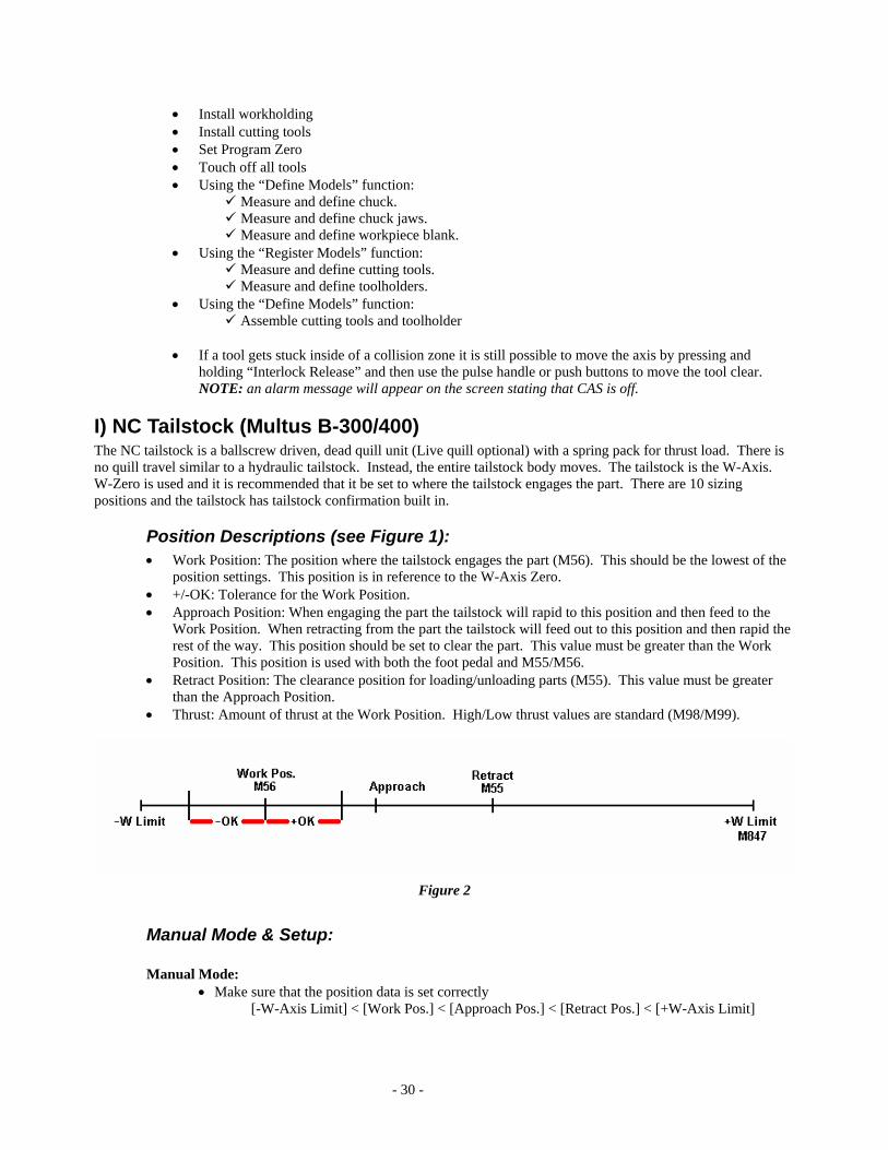
Manual Mode & Setup:
Manual Mode: • Make sure that the position data is set correctly
[-W-Axis Limit] < [Work Pos.] < [Approach Pos.] < [Retract Pos.] < [+W-Axis Limit]
- 31 -
• For Manual Advance the pedal has two trigger points. Slightly pressed will inch the tailstock forward. Press down fully and release will advance the tailstock to the Work Position.
• For Manual Retract press and hold retract pedal and the tailstock will move to the Retract Position or to the positive W-Axis soft limit. Tailstock motion will stop when the pedal is released.
Setup:
In MDI Mode: • Select the Sizing position desired. (Ex. G195 SP=1) • Set the thrust level (High M99/Low M98).
In Manual Mode: • Activate NC Tailstock data page using the black panel button. • Turn Teaching Mode on. • Press and release the Advance pedal (Reset button will stop tailstock advance)
Tailstock will engage the part at the thrust level set. • Go to W-Axis Zero Set and CAL 0. (It is recommended that W-Axis zero and Work Position
be set at the same point.) • Go to the tailstock Work Position and Cal 0. • Set Approach Position (> Work Position). • Set Retract Position (> Approach Position). • Retract tailstock • Turn off Teaching Mode.
Tailstock is set. Add notes about center hole parameter. Must be greater than Work Position + +OK + Center Hole + 5mm.
G/M-Codes: G195 Multiple sizing position command G195 SP=@@ M55 Tailstock retract position command ( disengage from part) M56 Tailstock sizing position command (engage in part) M98 Tailstock low pressure command M99 Tailstock high pressure command M167 Tailstock interlock release ON M168 Tailstock interlock release OFF M847 Tailstock retraction end position command ( move to W+ soft limit)
Conditions: • Tailstock parameter set to Center Work. • Turret at X-plus limit
Parameters: Position data is set in values relative to a W-Zero position. On a tailstock machine the W-axis is only used for the tailstock and has no reference to the program zero. Therefore, we recommend that W-Zero be set to the Work Position.
Work position - Where the center is engaged in part, smallest value and it is recommended that this should match the W-Axis zero. Approach position - rapid to position, then slow feed to work position Retract position - clearance position to be able to remove the part, less than plus soft limit
Note: if there is a miss-match of data it will create alarm 2371 Error in TS move command.
- 32 -
Address Characters:
SP=@@ @@= Multiple Sizing position No. (1-10)
Notes: • A maximum of 10 tailstock positions (Sizing Positions) can be set. • The pressure on the workpiece is controlled by spring pressure in the tailstock body (there is no quill). • Taper adjustment is standard. • Make sure that the position data is set correctly
[-W-Axis Limit] < [Work Pos.] < [Approach Pos.] < [Retract Pos.] < [+W-Axis Limit] • For Manual Advance the pedal has two trigger points. Slightly pressed will inch the tailstock forward.
Press down fully and release will advance the tailstock to the Work Position. • For Manual Retract press and hold retract pedal and the tailstock will move to the Retract Position or to the
positive W-Axis soft limit.
Program Example: (Multiple sizing command) N001 G00 X1000 Moves the X-axis to the + limit. N002 G195 SP=1 Multiple Sizing position command (Position #1 commanded) N003 M56 Sizing position command (moving to the #1 sizing position) N004 M3 S1000 : Cutting Program N100 M5 Spindle stop N101 M55 Retract position command (moving to the #1 retract position)
- 33 -
Appendix I
General Notes: E-control and newer 1. Always be sure to turn off commands or give priority to the opposing turret when leaving one spindle
to go to the other. (M110, G96, G110/G111, G94…) 2. Remember that when the turrets are not working together (not 4-axis) that the commands to the
spindle (M83/84, M88/89…) are the same as any two axis machine. Only when in 2-spindle mode would you need to use (M248/249, M288/289…)
3. Note that when making a Z-Zero Offset to the A or B-turret in G141 mode the direction of offset is reversed. Towards the spindle is a positive direction. This is because the ZA/ZB axis is on the same ballscrew for both L/R spindles and is setup +/- to the left spindle. Also note that programming is not affected by this. Programming towards the chuck is always a negative direction.
4. Always put the T0?0?0? (or TL=) command on a line with X- & Z-Axis commands. This holds true for all Okuma lathes. Correct programming procedure.
5. When using C-Axis in 4-axis mode. Only one of the turrets can command M110 and the following C-axis movements. The other turret may start up and use its M-Tools but only the one that commanded M110 can command C-positions. Then in turn only the turret that commanded M110 can command the M109.
6. Note that sometimes you will see differences when running the program in Dry Run, Machine Lock, Individual Mode, and Single Block or any combination of these. This is because with each one of these conditions different Confirmations/Interlocks may be required and also, as in individual mode, only applicable parts of the program will be read.
7. Note that when using Lower turret M-Tools on the right spindle it may be required to set Turret Parameter Bits in order to get the proper rotation of the M-Tool. (Please see manuals)
8. Note the following about P-Codes: • P-Codes must consecutively count up from 1. (Ex. P1, P2…or P10, P25…) • Usually you synchronize P-Codes (Both A/B have P10’S ). You don't have to synchronize (A-
Turret has P1, B has P2, A has P3…) • P-? (P minus value) can be used. This will reset the P-Code count up. • Don't overuse P-Codes. It could slow your program.
9. Note the following about M100: • There must be equal number of M100's for both G13/G14. • These codes act like P-Codes by holding up one turret for the other. • One unique feature of M100 is that it holds the read ahead character. • Could cause restart problems if over-used.
10. It is recommended that you create restart points in the program to make it easier for both setup and in reworking or saving parts. These would typically be located before and after processes such as transfer, C-Axis work, and other complex processes. In these cases you would restart just prior to M151, M110, M201…or just after M150, M109, M200…
11. Note that when performing a transfer at RPM you will need to use the M-Codes M185 and M247. M185 allows the main chuck to rotate at RPM while in the unclamp state. M247 does the same for the opposing chuck. M184 and M246 will return them to interlock status.
12. Note that the offsets for the lower turret are common for both left and right spindles. The number in the offset page is just added to the Z-Zero offset of the spindle mode commanded (G140/141).
13. It is recommended to establish the same spindle orientation for M19, M151 and M110. Do this for both spindles. This will ensure that features being processed on the left spindle can easily be identified on the right. You will need to set both parameters (LONG WORDS #40, 43,44) and CA/CB-ZERO offsets in order to do this.
- 34 -
Appendix II
Machine Set-up Machine Checks 1. Verify service has checked ALL alignments and Zero-sets:
a. Spindles individually, then to each other b. Lower turret alignment, then X-zero sets c. Upper turret alignment, will include B-axis checks as well, then X-Y zero sets
2. Check Machine Data management card to zero-sets and related parameters. 3. Calibrate touch setter 4. Set Soft Limits:
a. Set lower turret G140 z-minus, G141 z-plus in front of main spindle chuck. b. Set Upper turret G140 z-plus, G141 z-minus so rear of turret is clear of opposing chuck/part. c. Set Right spindle chuck/jaws plus limit to clear Left spindle chuck jaws d. Opt. Parameter: 1st-2nd Spindle: (9) B-turret to Sub interference
5. Set Parameters: a. Opt. Par., Other Function
i. 16- Torque delay time: 5 ii. 17- Torque limit command- 50
iii. 25- Program start mode- nothing b. Machine User Par., Turret/Door
i. Shortest path B-side: check on c. Machine User Par., Axis Control (When equipped with rapid over-ride switch this does not function.)
i. Rapid feed override: check on d. Machine System Par., Turret/Door, Page 3
i. One directional positioning enable – Un-check to eliminate extra turret move. NOTE: B-Axis positioning accuracy is not guaranteed when this parameter is turned off.
e. Mach. System Par., Airblow/Coolant, Page 2 i. M08/09 selection: 2
ii. M175/M174 selection: 2 f. Mach. Optional Par., B-Axis, Page 1
Note: Some of these settings are for clearance or collision avoidance reasons. Actual usage may require different settings, use extreme caution if there are interference zones because of the application.
Macturn Parameters B-axis User Parameter:
Slant mode angle value Tool edge offsets: ability to use a tool edge to set ‘Z’ zero and not spindle nose, like a standard turret.
Optional Par., MG Panel: Communication data for magazine input panel. Optional Par., B-axis: Tool offset functionality. B-axis System Parameter: One of alignment checks data. ‘X’ offset: distance of spindle centerline from turret rotation point, ideally should be zero ‘Z’ offset: distance of spindle nose from turret rotation point. M-axis Orientation: ATC system setting B-axis Angle: System data for turret angle positions ATC Home Position: Machine coordinates for tool changing and a return position, G21 HP=N. HP1: X, Y, Z- tool change position, Z- not specific on 250/350

- 35 -
HP4: X- positive soft limit, Y- turning position, Z- usually same as HP1 HP6: X, Y, Z- tool change position for sub-magazine, X, Y should be same as HP1 ATC Home Position Move: Ability to turn on/off particular axis movement for the G21 command. ATC Parameter: System data for ATC Machine User Par., ATC Tool Parameter: Allows control of specified functions by tool number. Machine System Par., Machine Position Point: System data for exchange arm Machine System Par., System Checkmode: Various items to allow manual control of ATC functions Machine System Par., ATC: System data of ATC functions Machine System Par., ATC Exchange Arm: System data for exchange arm.
- 36 -
Appendix III
Coolant
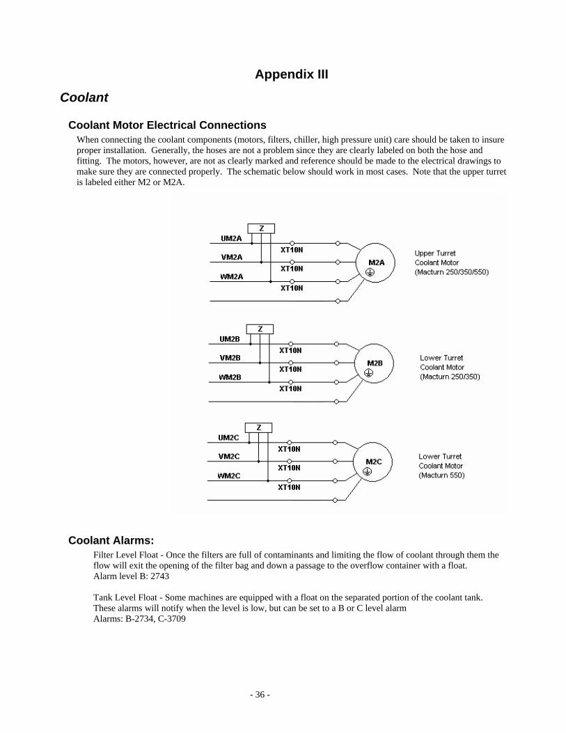
Coolant Motor Electrical Connections When connecting the coolant components (motors, filters, chiller, high pressure unit) care should be taken to insure proper installation. Generally, the hoses are not a problem since they are clearly labeled on both the hose and fitting. The motors, however, are not as clearly marked and reference should be made to the electrical drawings to make sure they are connected properly. The schematic below should work in most cases. Note that the upper turret is labeled either M2 or M2A.
Coolant Alarms: Filter Level Float - Once the filters are full of contaminants and limiting the flow of coolant through them the flow will exit the opening of the filter bag and down a passage to the overflow container with a float. Alarm level B: 2743 Tank Level Float - Some machines are equipped with a float on the separated portion of the coolant tank. These alarms will notify when the level is low, but can be set to a B or C level alarm Alarms: B-2734, C-3709
- 37 -
Appendix IV
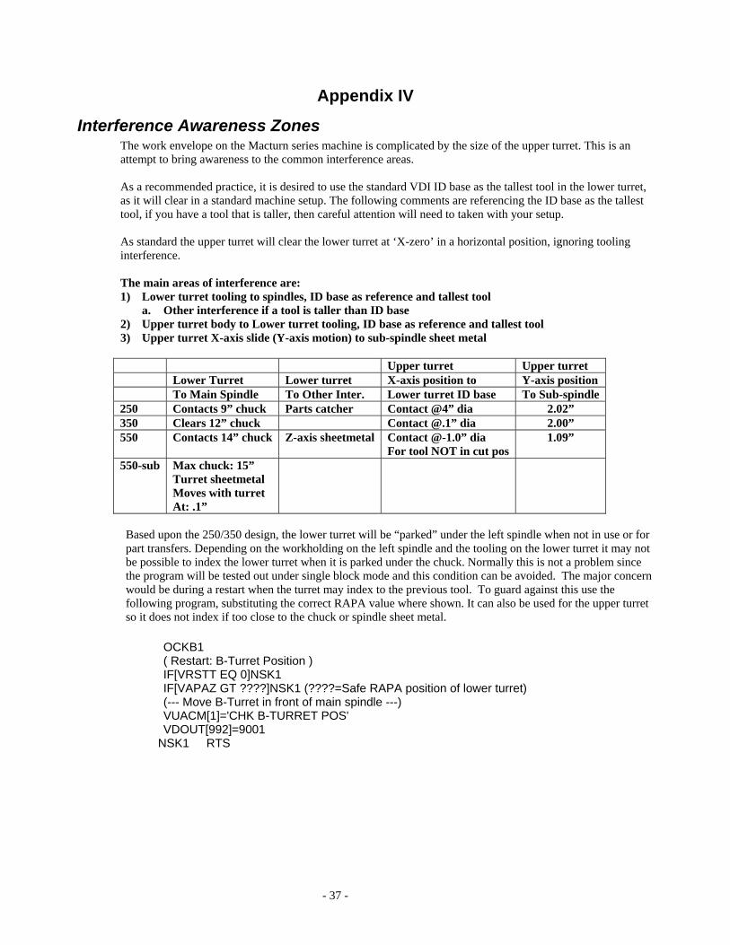
Interference Awareness Zones The work envelope on the Macturn series machine is complicated by the size of the upper turret. This is an attempt to bring awareness to the common interference areas. As a recommended practice, it is desired to use the standard VDI ID base as the tallest tool in the lower turret, as it will clear in a standard machine setup. The following comments are referencing the ID base as the tallest tool, if you have a tool that is taller, then careful attention will need to taken with your setup. As standard the upper turret will clear the lower turret at ‘X-zero’ in a horizontal position, ignoring tooling interference.
The main areas of interference are: 1) Lower turret tooling to spindles, ID base as reference and tallest tool
a. Other interference if a tool is taller than ID base 2) Upper turret body to Lower turret tooling, ID base as reference and tallest tool 3) Upper turret X-axis slide (Y-axis motion) to sub-spindle sheet metal Upper turret Upper turret Lower Turret Lower turret X-axis position to Y-axis position To Main Spindle To Other Inter. Lower turret ID base To Sub-spindle 250 Contacts 9” chuck Parts catcher Contact @4” dia 2.02” 350 Clears 12” chuck Contact @.1” dia 2.00” 550 Contacts 14” chuck Z-axis sheetmetal Contact @-1.0” dia
For tool NOT in cut pos 1.09”
550-sub Max chuck: 15” Turret sheetmetal Moves with turret At: .1”
Based upon the 250/350 design, the lower turret will be “parked” under the left spindle when not in use or for part transfers. Depending on the workholding on the left spindle and the tooling on the lower turret it may not be possible to index the lower turret when it is parked under the chuck. Normally this is not a problem since the program will be tested out under single block mode and this condition can be avoided. The major concern would be during a restart when the turret may index to the previous tool. To guard against this use the following program, substituting the correct RAPA value where shown. It can also be used for the upper turret so it does not index if too close to the chuck or spindle sheet metal.
OCKB1 ( Restart: B-Turret Position ) IF[VRSTT EQ 0]NSK1 IF[VAPAZ GT ????]NSK1 (????=Safe RAPA position of lower turret) (--- Move B-Turret in front of main spindle ---) VUACM[1]='CHK B-TURRET POS' VDOUT[992]=9001
NSK1 RTS
- 38 -
Appendix V
Cycle Time Reduction Track the time To check to see how long individual machine operations take save the splits to common variables as shown in the program below. This program times how long it takes to stop and orient the spindle.
G50 S1500 M3 S1500 M42 TIME=VDIN[1000] V32=[VDIN[1000]-TIME]/1000 TIME=VDIN[1000] M5 M19 V31=[VDIN[1000]-TIME]/1000 TIME=VDIN[1000] M2
Turret one direction enable From the factory all Macturns are set to position the turret in the same direction every time and in 2 steps. The first step swings the turret close to the target point but slightly to the clockwise side of the target. The second step moves the turret counter-clockwise to the final position. This is done to maximize accuracy. To eliminate some cycle time this extra move can be turned off however accuracy will suffer. A possible compromise is to turn the extra move off for roughing and non-critical finishing and then turn it on for critical finishing. To do this: un-check the parameter and use M604/M605 in the program to turn it off/on. These commands are modal but are cancelled by reset, M2, and power-off. Note: The operator must confirm that, where this parameter is turned off, the customer’s required tolerances are being maintained. B-Axis positioning accuracy is not guaranteed when this parameter is turned off. Refer to turret parameter section for more information.
High speed M110 command Optional Parameter (Multiple Machining): C-Axis Return to Origin - Eliminate the Zero-Positioning of the C-Axis when shifting to C-Axis mode (M110). Selected by Optional Parameter (Multiple Machining); C-Axis Return to Origin.
Enable = Position to zero Disable = Position cancel
M153: M-tool Spindle Interlock Off Simultaneous motion of C-axis, M-spindle rotation and Feed-axis motion - C-axis connection, M-Axis rotation and feed axis motion can be executed at the same time.
<Reference program> Standard Programming Method N000 M110 N001 G00 X250 Z200 C180 T0101 SB=2000 M13 M63 N002 X100 Z10 N003 G01 Z-10 F100
Cycle Time Reduction Programming Method N000 M110 G00 X250 Z200 T0101 SB=2000 M13 M63 M153 N001 X100 Z10 C180 N003 G01 Z-10 F100

- 39 -
Home Position instead of Limits. Instead of sending the turret to the X limit at the end of an operation send it to the tool change home position: G21 HP=4. With the P200 control this command requires Y-mode (G138) to be turned on.

- 40 -
Appendix VI
Program Examples Reference Drawing This drawing & tool list is used for several of the programming examples. This drawing is from ADMAC tutorial, #4.
- 41 -
Appendix VII Macturn Publications
Okuma Manuals Publication # Control Machine Title
5262 5238 5240 5232 5342 5264 5323 5322
OSP-P200L Macturn/Multus Operation manual Programming Manual Special Functions Manual Alarm & Error List Super-Nurbs CAS Instruction- Basic CAS Instruction- Application CAS Instruction- Additional functions
5097 4802 5287
OSP-P100L Macturn series All lathes
Operation Manual Gauging Systems Y-axis Gauging
4696 5005 5029 5277 4466 4420
OSP-E100L Macturn 250 Operation Manual Sub-Magazine spec L-Tool 45º Index Function B-axis Control function (full B) IT Plaza Set/DNC-DT/DNC-RT DNC-B/C
4436 OSPU100L Macturn series Operation manual 4108 OSP7000L Macturn 30/50 Operation manual
Service Publications
Applications Engineering Publications Publication # Control Title AB-0176 E100L Effective Rapid Override parameter AB-0179 E100L Heavy Tool parameter AB-0180 E100L Master G & M-code list for lathes AB-0195 Macturn B-axis contouring accuracy AB-0196 Macturn 550 Tool change times AB-0199 Cycle time reduction for multi-function lathes AB-0200 Macturn tool offset variation AB-0203 Quick Edit Function AB-0213 Macturn Touch-Sensor Gauging W/Tool Compensation Multi-
function System. AB-0215 Common Variables; Macturn Global Software update
Ref: Distributor Bulletin OSP-0003 AB-0216 System Variables; Macturn Global Software update
Ref: Distributor Bulletin OSP-0003 AB-0219 Macturn H1 CAT-spec turrets and Lathe Tool Index Function AB-0225 Multus/Macturn Chip Removal Cycle: OM450/OM451/OM452 AB-0230 Setting M-axis Orientation

- 42 -
Appendix VIII
ATC Operation Sequence: Multus B-300/400
S1 Waiting for next tool command S16 EA RS position/Shutter close S2 Magazine (MG) indexing S17 MG return pot indexing (EA) S3 Ready station (RS) tool extraction S18 RS change position S4 RS change position S19 RS tool insertion S5 RS tool extraction S20 RS MG position S6 RS MG position S21 RS tool extraction S7 Waiting for machine cycle end S8 Tool change arm (EA) tool
insertion/Shutter close
S9 EA Rotation (90°) EA M Tool change arm S10 Turret Tool clamp RS Ready station S11 EA tool extraction MG Magazine S12 EA Rotation (180°) S13 EA tool insertion MT command : S1 to S7 S14 Turret Tool clamp M6 command : S8 to S21 S15 EA Rotation 90° M228 command : S7 to S1
Macturn 250/350 standard magazine specification
S1 Waiting for tool selection command (MT) S10 Shutter close S2 Magazine indexing S11 MG indexing tool return pot (RS) S3 RS tool insertion S12 RS tool insertion S4 RS tool change position Shutter 2 open S5 RS tool extraction S13 RS magazine possible Shutter 2 close S14 RS tool extraction S6 Waiting for tool change command (M6) S7 MG start indexing tool return pot S8 Shutter open S9 EA gripping EA M Tool change arm Turret tool unclamp RS Ready station EA tool extraction MG Magazine EA 180° rotation EA tool insertion Turret clamp tool MT command : S1 to S6 EA retract possible M6 command : S7 to S14 M228 command : S6 to S1
Macturn 550 standard magazine specification
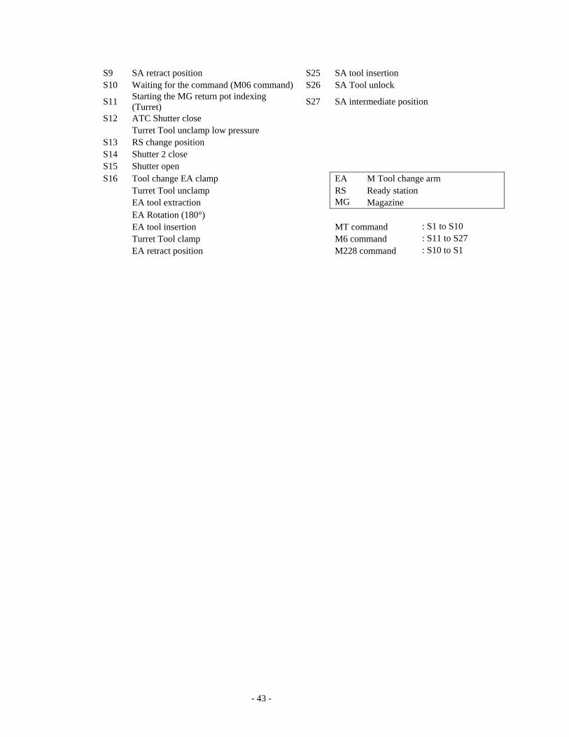
S1 Waiting for next tool command S17 Shutter close S2 Magazine (MG) indexing S18 Shutter 2 close S3 Sub-arm (SA) MG position S12 RS MG position S4 SA Tool lock S20 MG return pot indexing (RS) S5 SA tool extraction S21 SA RS position S6 SA RS position S22 SA Tool lock S7 SA tool insertion S23 SA tool extraction S8 SA Tool unlock S24 SA MG position
- 43 -
S9 SA retract position S25 SA tool insertion S10 Waiting for the command (M06 command) S26 SA Tool unlock
S11 Starting the MG return pot indexing (Turret) S27 SA intermediate position
S12 ATC Shutter close Turret Tool unclamp low pressure S13 RS change position S14 Shutter 2 close S15 Shutter open S16 Tool change EA clamp EA M Tool change arm Turret Tool unclamp RS Ready station EA tool extraction MG Magazine EA Rotation (180°) EA tool insertion MT command : S1 to S10 Turret Tool clamp M6 command : S11 to S27 EA retract position M228 command : S10 to S1
- 44 -
Index
5
5262 LE · 41
5264 LE32-116 · 41
A
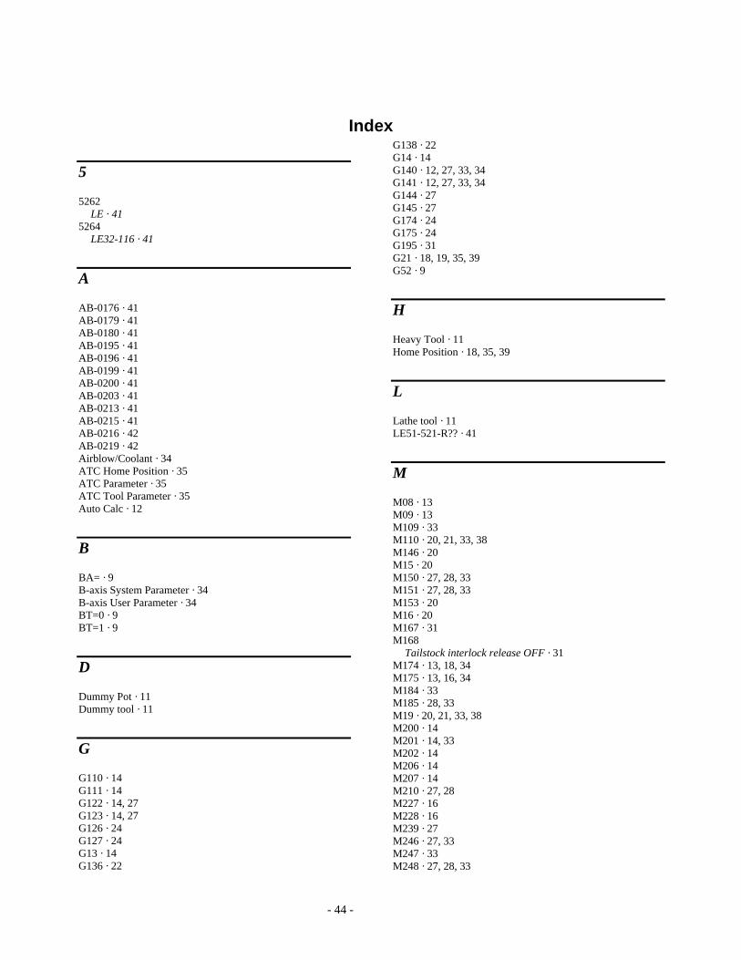
AB-0176 · 41 AB-0179 · 41 AB-0180 · 41 AB-0195 · 41 AB-0196 · 41 AB-0199 · 41 AB-0200 · 41 AB-0203 · 41 AB-0213 · 41 AB-0215 · 41 AB-0216 · 42 AB-0219 · 42 Airblow/Coolant · 34 ATC Home Position · 35 ATC Parameter · 35 ATC Tool Parameter · 35 Auto Calc · 12
B
BA= · 9 B-axis System Parameter · 34 B-axis User Parameter · 34 BT=0 · 9 BT=1 · 9
D
Dummy Pot · 11 Dummy tool · 11
G
G110 · 14 G111 · 14 G122 · 14, 27 G123 · 14, 27 G126 · 24 G127 · 24 G13 · 14 G136 · 22
G138 · 22 G14 · 14 G140 · 12, 27, 33, 34 G141 · 12, 27, 33, 34 G144 · 27 G145 · 27 G174 · 24 G175 · 24 G195 · 31 G21 · 18, 19, 35, 39 G52 · 9
H
Heavy Tool · 11 Home Position · 18, 35, 39
L
Lathe tool · 11 LE51-521-R?? · 41
M
M08 · 13 M09 · 13 M109 · 33 M110 · 20, 21, 33, 38 M146 · 20 M15 · 20 M150 · 27, 28, 33 M151 · 27, 28, 33 M153 · 20 M16 · 20 M167 · 31 M168
Tailstock interlock release OFF · 31 M174 · 13, 18, 34 M175 · 13, 16, 34 M184 · 33 M185 · 28, 33 M19 · 20, 21, 33, 38 M200 · 14 M201 · 14, 33 M202 · 14 M206 · 14 M207 · 14 M210 · 27, 28 M227 · 16 M228 · 16 M239 · 27 M246 · 27, 33 M247 · 33 M248 · 27, 28, 33
- 45 -
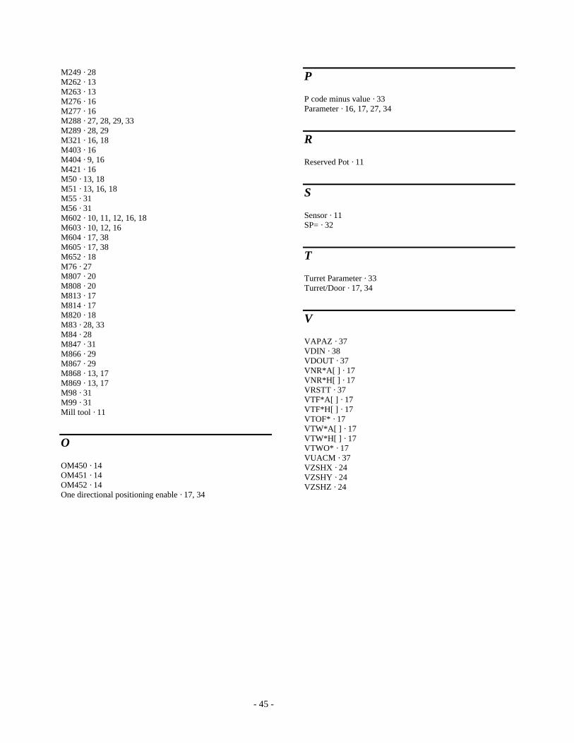
M249 · 28 M262 · 13 M263 · 13 M276 · 16 M277 · 16 M288 · 27, 28, 29, 33 M289 · 28, 29 M321 · 16, 18 M403 · 16 M404 · 9, 16 M421 · 16 M50 · 13, 18 M51 · 13, 16, 18 M55 · 31 M56 · 31 M602 · 10, 11, 12, 16, 18 M603 · 10, 12, 16 M604 · 17, 38 M605 · 17, 38 M652 · 18 M76 · 27 M807 · 20 M808 · 20 M813 · 17 M814 · 17 M820 · 18 M83 · 28, 33 M84 · 28 M847 · 31 M866 · 29 M867 · 29 M868 · 13, 17 M869 · 13, 17 M98 · 31 M99 · 31 Mill tool · 11
O
OM450 · 14 OM451 · 14 OM452 · 14 One directional positioning enable · 17, 34
P
P code minus value · 33 Parameter · 16, 17, 27, 34
R
Reserved Pot · 11
S
Sensor · 11 SP= · 32
T
Turret Parameter · 33 Turret/Door · 17, 34
V
VAPAZ · 37 VDIN · 38 VDOUT · 37 VNR*A[ ] · 17 VNR*H[ ] · 17 VRSTT · 37 VTF*A[ ] · 17 VTF*H[ ] · 17 VTOF* · 17 VTW*A[ ] · 17 VTW*H[ ] · 17 VTWO* · 17 VUACM · 37 VZSHX · 24 VZSHY · 24 VZSHZ · 24


