• Warnings and legal information• Installation and terminals• Display description• Operation• Settings• Communication• I/O options• Alarming• Utility software• More information• Specifications
2
Warnings, legal information and safety
Legal information and disclaimerDEIF takes no responsibility for installation or opera-tion of the multi-instument. If there is any doubt about how to install or operate the multi-instrument, the company responsible for the installation or the operation of the set must be contacted.
The DEIF unit is not to be opened by unauthorised personnel. If opened anyway, the warranty will be lost.
DisclaimerDEIF A/S reserves the right to change any of the contents of this document without prior notice.
The English version of this document always contains the most recent and up-to-date information about the product. DEIF does not take responsibility for the accuracy of translations, and translations might not be updated at the same time as the English document. If there is any discrepancy, the English version prevails.
Safety issuesInstalling and operating the DEIF unit may imply work with dangerous currents and voltages. Therefore, the installation should only be carried out by authorised personnel who understand the risks involved in working with live electrical equipment.
Be aware of the hazardous live currents and volt-ages. Do not touch any AC measurement in- puts as this could lead to injury or death.
Electrostatic discharge awarenessSufficient care must be taken to protect the terminal against static discharges during the installation. Once the unit is installed and connected, these precautions are no longer necessary.
Factory settingsThe DEIF unit is delivered from factory with certain factory settings. These are based on average
values and are not necessarily the correct settings for matching the engine/generator set in question. Precautions must be taken to check the settings before running the engine/generator set.
About the quick start guide General purposeThis quick start guide mainly includes general product information, mounting instructions and wiring descriptions.
The general purpose of this document is to help the user with the first steps of installing and using the DEIF system.
Please make sure that you also read the installation instructions before starting to work with the DEIF unit and the genset to be controlled. Failure to do this could result in human injury or damage to the equipment.
Intended usersThis quick start guide is mainly intended for the panel builder in charge. On the basis of this docu-ment, the panel builder designer will give the electri-cian the information he needs in order to get started with the installation. For detailed electrical drawings, please see the installation instructions.
Contents and overall structureThis document is divided into chapters, and in order to make the structure simple and easy to use, each chapter will begin from the top of a new page.
According to the instrument model, the current input type is for 1/5 A CTs or Flexible Current Transformer. Check the instrument model and con-nect the voltage and current inputs according to the following wiring diagrams.
General information
3
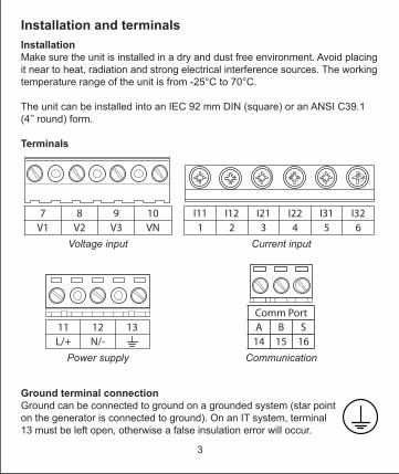
InstallationMake sure the unit is installed in a dry and dust free environment. Avoid placing it near to heat, radiation and strong electrical interference sources. The working temperature range of the unit is from -25°C to 70°C.
The unit can be installed into an IEC 92 mm DIN (square) or an ANSI C39.1 (4’’ round) form.
Terminals
7 8 9 10V1 V2 V3 VN
Voltage input
I11 I12 I21 I22 I31 I321 2 3 4 5 6
Current input
11 12 13L/+ N/-
Power supply
Comm PortA B S14 15 16
Communication
Ground terminal connectionGround can be connected to ground on a grounded system (star point on the generator is connected to ground). On an IT system, terminal 13 must be left open, otherwise a false insulation error will occur.
Installation and terminals
4
9
1112
13 14 15 16
17
1
4
5
6
7
8
2
3
10
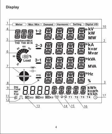
Display
5
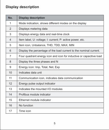
No. Display description
1 Mode indication, shows different modes on the display
2 Displays metering data
3 Displays energy data and real-time clock
4 Item label, U: voltage; I: current; P: active power, etc.
5 Item icon, Unbalance, THD, TDD, MAX, MIN
6 Display the percentage of the load current to the nominal current.
7 Four quadrant energy icon and icon for inductive or capacitive load
8 Display the three phases and N
9 Energy icon: Imp, Total, Net, Exp
10 Indicates data unit
11 Communication icon, indicates data communication
12 Energy pulse output indicator
13 Indicates the mounted I/O modules
14 Profibus module indicator
15 Ethernet module indicator
16 No function
17 Time icon
Display description
6
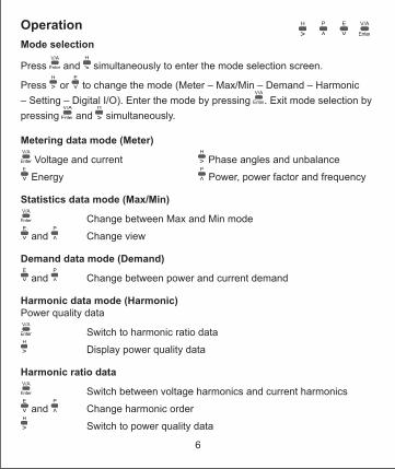
Mode selection
Press and simultaneously to enter the mode selection screen.
Press or to change the mode (Meter – Max/Min – Demand – Harmonic – Setting – Digital I/O). Enter the mode by pressing . Exit mode selection by pressing and simultaneously.
Metering data mode (Meter)
Voltage and current Phase angles and unbalance Energy Power, power factor and frequency
Statistics data mode (Max/Min)
Change between Max and Min mode and Change view
Demand data mode (Demand)
and Change between power and current demand
Harmonic data mode (Harmonic)Power quality data
Switch to harmonic ratio dataDisplay power quality data
Harmonic ratio data
Switch between voltage harmonics and current harmonics and Change harmonic order
Switch to power quality data
Operation
7
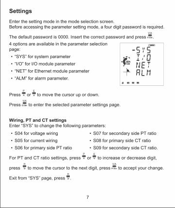
Enter the setting mode in the mode selection screen.Before accessing the parameter setting mode, a four digit password is required.
The default password is 0000. Insert the correct password and press .4 options are available in the parameter selection page:• “SYS” for system parameter• “I/O” for I/O module parameter • “NET” for Ethernet module parameter• “ALM” for alarm parameter.
Press or to move the cursor up or down.
Press to enter the selected parameter settings page.
Wiring, PT and CT settingsEnter “SYS” to change the following parameters:• S04 for voltage wiring• S05 for current wiring• S06 for primary side PT ratio
• S07 for secondary side PT ratio• S08 for primary side CT ratio• S09 for secondary side CT ratio.
For PT and CT ratio settings, press or to increase or decrease digit,
press to move the cursor to the next digit, press to accept your change.
Exit from “SYS” page, press .
Settings
8
The unit has a standard RS485 communication port and optional Ethernet or Profibus communication modules. The unit supports dual communication which means the RS485 serial communication can be used together with either an Ethernet or a Profibus connection.
Modbus communication settingsThe communication terminals are A, B, S (14, 15, 16). A is the differential signal +, B is the differential signal –, and S is the shield. Up to 32 devices can be connected on an RS485 Modbus. The overall length of the Modbus cable cannot exceed 1000 m. The communication terminals are A, B, S (14, 15, 16). A is the differential signal +, B is the differential signal –, and S is the shield. Up to 32 devices can be connected on an RS485 Modbus. The overall length of the Modbus cable cannot exceed 1000 m. Enter “SYS” page and scroll to page S01 to set the device address and S02 to change baud rate. Default settings are: Device address: 1 Baud rate: 19200 bps. Enter “SYS” page and scroll to page S01 to set the device address.
Ethernet communication settings (optional)AXM-WEB-PUSH default settings are:• IP Address (192.168.1.254)• Gateway (192.168.1.1)
• Subnet Mask (255.255.255.0)• Primary DNS Server (202.106.0.20)
Change the settings in the setting mode and enter the “NET” page.
Exit “NET” page by pressing .To enter the settings webpage, the default password is: 12345678
Profibus parameters can be set or viewed either from the unit front or through communication using utility software. Please refer to the Profibus module user’s manual chapter 3 “Application of Profibus DP Protocol” for operation details.
Communication
9
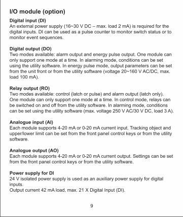
Digital input (DI)An external power supply (16~30 V DC – max. load 2 mA) is required for the digital inputs. DI can be used as a pulse counter to monitor switch status or to monitor event sequences.
Digital output (DO)Two modes available: alarm output and energy pulse output. One module can only support one mode at a time. In alarming mode, conditions can be set using the utility software. In energy pulse mode, output parameters can be set from the unit front or from the utility software (voltage 20~160 V AC/DC, max. load 100 mA).
Relay output (RO)Two modes available: control (latch or pulse) and alarm output (latch only).One module can only support one mode at a time. In control mode, relays can be switched on and off from the utility software. In alarming mode, conditions can be set using the utility software (max. voltage 250 V AC/30 V DC, load 3 A).
Analogue input (AI)Each module supports 4-20 mA or 0-20 mA current input. Tracking object and upper/lower limit can be set from the front panel control keys or from the utility software.
Analogue output (AO)Each module supports 4-20 mA or 0-20 mA current output. Settings can be set from the front panel control keys or from the utility software.
Power supply for DI24 V isolated power supply is used as an auxiliary power supply for digital inputs. Output current 42 mA load, max. 21 X Digital Input (DI).
I/O module (option)
10
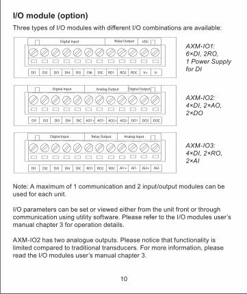
Three types of I/O modules with different I/O combinations are available:
Note: A maximum of 1 communication and 2 input/output modules can be used for each unit.
I/O parameters can be set or viewed either from the unit front or through communication using utility software. Please refer to the I/O modules user’s manual chapter 3 for operation details.
AXM-IO2 has two analogue outputs. Please notice that functionality is limited compared to traditional transducers. For more information, please read the I/O modules user’s manual chapter 3.
I/O module (option)
11
Up to 16 alarming channels can be selected from 48 available parameters.Alarming channels and conditions can be set from the utility software.Please refer to MIC-2 MKII user’s manual section 4.4 for details.
Utility software
The free utility software DEIF View is a user-friendly real time monitoring and data logging for energy saving and power quality analysis. This software is intended for users to monitor multiple parameters continuously. It allows for real-time monitoring and maintenance. Download DEIF View: www.deif.com/software/software-download
More information
The following can be downloaded from www.deif.com:• MIC-2 MKII user manual• Ethernet TCP/IP - AXM-WEB-PUSH manual• AXM-Profibus – AXM-PROFI manual• I/O modules - AXM manual• MIC-2 MKII utility software• GSD file for Profibus
Alarming
12
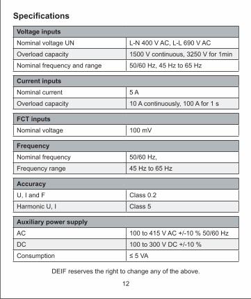
Voltage inputsNominal voltage UN L-N 400 V AC, L-L 690 V AC
Overload capacity 1500 V continuous, 3250 V for 1min
Nominal frequency and range 50/60 Hz, 45 Hz to 65 Hz
Current inputsNominal current 5 A
Overload capacity 10 A continuously, 100 A for 1 s
FCT inputsNominal voltage 100 mV
FrequencyNominal frequency 50/60 Hz,
Frequency range 45 Hz to 65 Hz
AccuracyU, I and F Class 0.2
Harmonic U, I Class 5
Auxiliary power supplyAC 100 to 415 V AC +/-10 % 50/60 Hz
DC 100 to 300 V DC +/-10 %
Consumption ≤ 5 VA
DEIF reserves the right to change any of the above.