41
Multi-Mode Continuous Wave Fiber Laser User Guide 1000W/1200W/1500W Wuhan Raycus Fiber Laser Technologies Co., Ltd

Multi-Mode
Continuous Wave Fiber Laser
User Guide
1000W/1200W/1500W
Wuhan Raycus Fiber Laser Technologies Co., Ltd

Wuhan Raycus Fiber Laser Technologies Co., Ltd. User Guide 1000W/1200W/1500W Ver: 1.0
TABLE OF CONTENTS
1 Safety Information ..................................................................................................................... 1
1.1 Symbols Used in this User Guide ..................................................................................... 1
1.2 Laser Classification ........................................................................................................... 1
1.3 Optical Safety .................................................................................................................... 2
1.4 Electrical Safety ................................................................................................................ 2
1.5 Other Safety Rules ............................................................................................................ 3
2 Product Description ................................................................................................................... 4
2.1 Features ............................................................................................................................. 4
2.2 Package Contents .............................................................................................................. 5
2.3 Unpacking and Inspection ................................................................................................. 5
2.4 Operation Environment ..................................................................................................... 6
2.5 Announcements: ................................................................................................................ 6
2.6 Specifications .................................................................................................................... 7 3 Installation .................................................................................................................................. 9
3.1 Dimensions ........................................................................................................................ 9
3.2 Installation Procedure...................................................................................................... 11
3.3 Cooling Requirements..................................................................................................... 13
4 Using the Product ..................................................................................................................... 15
4.1 Front Panel ...................................................................................................................... 15
4.2 Rear Panel ....................................................................................................................... 16
4.3 Power Connection ........................................................................................................... 17
4.4 Control Wire Definitions................................................................................................. 19
4.5 Control Modes................................................................................................................. 23
4.6 Entering a Control Mode................................................................................................. 24
4.7 Hyper Terminal Mode ..................................................................................................... 24
4.8 RS-232 Mode .................................................................................................................. 32
4.9 AD Mode ......................................................................................................................... 35 5 Warranty, Return and Maintenance ...................................................................................... 38
5.1 General Warranty ............................................................................................................ 38
5.2 Limitations of Warranty .................................................................................................. 38
5.3 Service and Repair .......................................................................................................... 38

Wuhan Raycus Fiber Laser Technologies Co., Ltd. User Guide 1000W/1200W/1500W Ver: 1.0
1
1 Safety Information
Thank you for choosing Raycus fiber laser. This User Guide provides important safety, operation,
warranty and other information. Please read it carefully before you use this product. In order to
ensure safe operation and optimal performance of the product, please follow the warnings,
cautions, operating procedures and other instructions accordingly.
1.1 Symbols Used in this User Guide
WARNING: Describes a hazard that lead to a personal injury or
death.
CAUTION: Describes a hazard that lead to a minor personal injury or
product damage.
1.2 Laser Classification
This series of lasers are classified as a high power Class 4 laser instrument according to the
European Community standards EN 60825-1, clause 9. This product emits invisible laser
radiation at or around a wavelength of 1080 nm, and the total light power radiated from the
optical output is greater than 1000W/1200W/1500W (depending on model). Direct or indirect
exposure of this level of light intensity may cause damage to the eye or skin. Despite the
radiation being invisible, the beam may cause irreversible damage to the retina and/or cornea.
Appropriate and approved laser safety eyewear must be worn all the time while the laser is
operational.

Wuhan Raycus Fiber Laser Technologies Co., Ltd. User Guide 1000W/1200W/1500W Ver: 1.0
2
WARNING: You must use appropriate laser safety eyewear when
operating this device. The laser safety eyewear is selected according to
the range of wavelengths emitted from this product. The end user must
ensure that the laser safety eyewear used protects against light emitted
by the device over its entire range of wavelengths-900nm~1100nm.
Please verify that the personal protective equipment (e.g. enclosures,
viewing windows or viewports, eyewear, etc.) being utilized is adequate
for the output power and wavelength range.
1.3 Optical Safety
Any dust on the end of the collimator assembly can burn the lens and damage the laser.
CAUTION: If the output of the device is delivered through a lens with
an anti-reflection coating, make sure that the lens is of good quality and
clean.
1.4 Electrical Safety
(1) Make sure your product is grounded through the PE line of the AC power cord. The
grounding must be firm and reliable.
WARNING: Any interruption from the protective earth can result in
personal injury.
(2) Make sure that the correct voltage of the AC power source is used.

Wuhan Raycus Fiber Laser Technologies Co., Ltd. User Guide 1000W/1200W/1500W Ver: 1.0
3
CAUTION: Failure to use the correct voltage could damage the
product.
(3) There are no operator serviceable parts inside, so do not try to remove covers, or electrical
shock may be caused, and warranty will be void.
1.5 Other Safety Rules
(1) Never look into the laser output port when power is supplied to the laser.
(2) Avoid using the laser in a dim or darkened environment.
(3) If this device is used in a manner not specified in this document, the protection provided by
the device may be impaired and the warranty will be voided.
(4) Do not remove the covers of the laser, or the warranty will be void. All maintenance must be
performed in Raycus or by qualified Raycus personnel.
Wuhan Raycus Fiber Laser Technologies Co., Ltd. User Guide 1000W/1200W/1500W Ver: 1.0
4
2 Product Description
2.1 Features
Your Raycus CW fiber laser is designed for industrial and scientific research applications with
high pump conversion efficiency, low power consumption and excellent beam quality. It is
compact and ready to use. It can be used as a stand-alone unit or easily inserted into user‟s
apparatus.
Main Features:
High beam quality
Fiber delivery
Reliable, long lifetime
Maintenance free operation
High wall-plug efficiency
Convenient control interface
Fast modulation
Applications:
Cutting
Welding
Scientific research
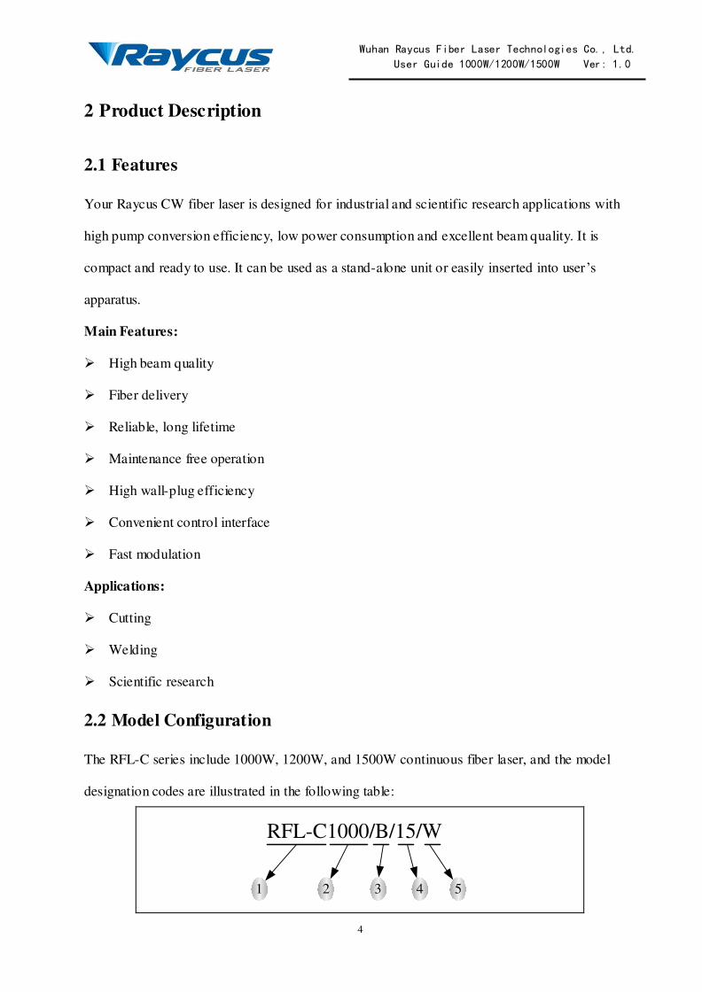
2.2 Model Configuration
The RFL-C series include 1000W, 1200W, and 1500W continuous fiber laser, and the model
designation codes are illustrated in the following table:
RFL-C1000/B/15/W
1 2 3 4 5

Wuhan Raycus Fiber Laser Technologies Co., Ltd. User Guide 1000W/1200W/1500W Ver: 1.0
5
1 RFL-C series, continuous wave fiber laser
2 Power in W, there are 1000W, 1200W and 1500W in this laser
series
3 Wavelength, „B‟ indicates the wavelength is 1080nm, and the
wavelength of all the models in the series is 1080nm
4 Length of delivery cable in meter, 10m and 15m optional
5 Cooling method, „W‟ indicates water cooling, „A‟ indicates air
cooling
Table 1: Model Names and Designation Codes
Usually we omit the suffix and present the model name as RFL-C1000, RFL-C1200, etc.
However, you can find the complete model name on the identification plate.
2.3 Package Contents
Please refer to the packing list accompanying the shipment to check the items included.
2.4 Unpacking and Inspection
Your Raycus CW fiber laser is shipped in a package designed to provide maximum protection.
Upon delivery, please inspect all packaging for evidence of mishandling or damage. If you find
any evidence of mishandling, please save the damaged material and contact the shipping agent
and Raycus immediately.
Remove all the contents from the packing case. Take extra care when removing the unit from the
packing case to ensure that the fiber optic cable is not snagged and damaged. A comprehensive
packing list is included with the system documentation. Check all items against the list and
contact Raycus immediately if there is any missing item or evident damage to the unit. DO NOT
attempt to install or operate the laser, if there is any evidence or suspected damage to the unit.

Wuhan Raycus Fiber Laser Technologies Co., Ltd. User Guide 1000W/1200W/1500W Ver: 1.0
6
It is recommended to retain the packing materials, as they will be necessary if you ever need to
ship the unit back for service at a later date.
CAUTION: The fiber optic cable and output head are precise optic
instrument, ANY vibration, twist or excessive bend will damage the
instrument.
2.5 Operation Environment
The operation voltage for the product: 380VAC±10%, 50/60Hz, three phase with neutral line.
Warning:
(1) Make sure the instrument is properly grounded before you use it.
(2) There are no user serviceable parts, equipment or assemblies inside the product. All service
and maintenance shall be performed by qualified Raycus personnel. In order to prevent
electric shock, please do not break the seal or uncover the cap. Failure to comply with this
instruction will void the warranty.
(3) The output terminal of the laser is connected to an optic delivery cable. Please inspect the
output head carefully for dust or other contaminations. Use appropriate lens paper to clean it
if necessary.
(4) Failure to follow the instructions may cause malfunction and damage to the device.
(5) It is not allowed to install the output terminal when the laser is in operation.
(6) Do not look into the output terminal directly. Wear appropriate protective eye glasses all the
time when operating the laser.
2.6 Announcements:
Please make sure that the correct voltage of AC power source is used. Failure to connect power
source correctly will damage the device. Use of controls or adjustments other than those
specified herein may result in hazardous radiation and damage to the laser. It is critical to keep
Wuhan Raycus Fiber Laser Technologies Co., Ltd. User Guide 1000W/1200W/1500W Ver: 1.0
7
the lens clean. Please cap the output terminal when it is not in use. Do not touch the output lens.
If necessary, you can use appropriate lens paper and alcohol to clean the lens. Failure to follow
the specified instuctions may result in the loss of laser power. Such loss is not covered under
warranty.
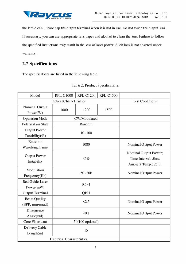
2.7 Specifications
The specifications are listed in the following table.
Table 2: Product Specifications
Model RFL-C1000 RFL-C1200 RFL-C1500
Optical Characteristics Test Conditions
Nominal Output
Power(W) 1000 1200 1500
Operation Mode CW/Modulated
Polarization State Random
Output Power
Tunability(%) 10~100
Emission
Wavelength(nm) 1080 Nominal Output Power
Output Power
Instability <5%
Nominal Output Power;
Time Interval: 5hrs;
Ambient Temp.: 25℃
Modulation
Frequency(Hz) 50~20k Nominal Output Power
Red Guide Laser
Power(mW) 0.5~1
Output Terminal QBH
Beam Quality
(BPP, mm•mrad) <2.5 Nominal Output Power
Divergence
Angle(rad) <0.1 Nominal Output Power
Core Fiber(μm) 50(100 optional)
Delivery Cable
Length(m) 15
Electrical Characteristics

Wuhan Raycus Fiber Laser Technologies Co., Ltd. User Guide 1000W/1200W/1500W Ver: 1.0
8
Power Supply AC 380V±10%, 50/60Hz, Three Phase
with Neutral Line
Max. Power
Consumption(W) 5000 6000 7500
Control Mode Hyper Terminal/RS-232/AD
Other Characteristics
Dimensions(W×D×
H) 620×740×932(inc. handles)
Weight(kg) <150
Operating Ambient
Temperature(℃) 10~40
Humidity (%) <70
Storage
Temperature(℃) -10~60
Cooling Method Water Cooling
Wuhan Raycus Fiber Laser Technologies Co., Ltd. User Guide 1000W/1200W/1500W Ver: 1.0
9
3 Installation
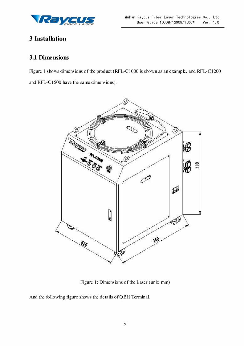
3.1 Dimensions
Figure 1 shows dimensions of the product (RFL-C1000 is shown as an example, and RFL-C1200
and RFL-C1500 have the same dimensions).
Figure 1: Dimensions of the Laser (unit: mm)
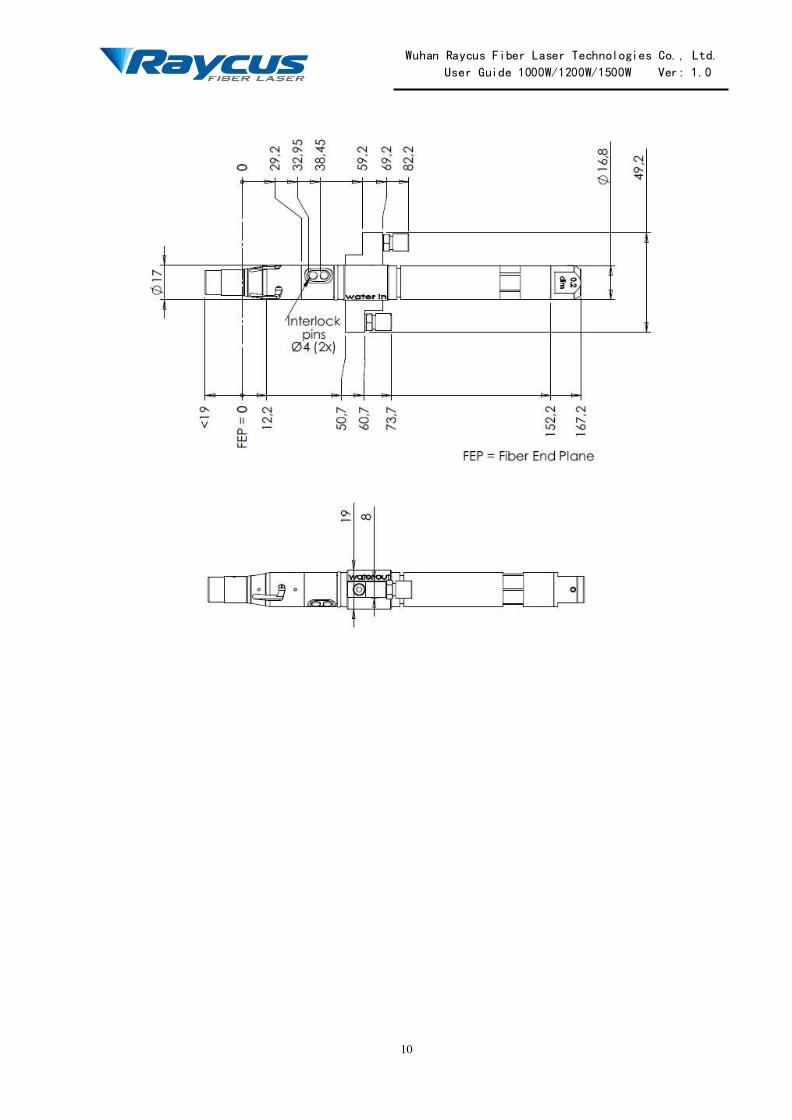
And the following figure shows the details of QBH Terminal.
Wuhan Raycus Fiber Laser Technologies Co., Ltd. User Guide 1000W/1200W/1500W Ver: 1.0
10

Wuhan Raycus Fiber Laser Technologies Co., Ltd. User Guide 1000W/1200W/1500W Ver: 1.0
11
Figure 2: QBH Output Terminal (unit: mm)
Note: The two interlock pins on the output terminal must be shorted before the laser is turned on.
Usually there is shorted contacts in the processing head, please check the head to ensure that.
3.2 Installation Procedure
(1) Check if the power supply has the correct voltage (380VAC±10%,50/60Hz), and the earth
line is connected reliably.
(2) Place the Fiber Laser Module firmly on the desirable position.
(3) Check the output terminal and clean it if necessary.This procedure must be performed by
Raycus personnel or person authorized by Raycus.
(4) Connect the power cable and control cable to the Fiber Laser when power supply is OFF.
(5) Insert the water tube into the inlet and outlet.

Wuhan Raycus Fiber Laser Technologies Co., Ltd. User Guide 1000W/1200W/1500W Ver: 1.0
12
(6) The optic fiber cable must not be bent with the radius less than 30 cm during transportation,
storage and when in use.
There are four swinging rings on the top of the product and four wheels on the bottom, with
which you can lift or move the product. The rings and wheels are shown in Figure 3
1. Swinging rings; 2. Wheels
Figure 3: The Swinging Rings and Wheels on the Product
CAUTION: All the cables can only be connected when power supply is
off. Hot plug may damage the laser.
CAUTION: Ensure that there are no fiber bends with radius less than 30
cm. Avoid excessive twisting and tight bends during the robotic arm
movements. Tight bends will damage the Laser system.

Wuhan Raycus Fiber Laser Technologies Co., Ltd. User Guide 1000W/1200W/1500W Ver: 1.0
13
3.3 Cooling Requirements
Table 3: Cooling Requirements
Parameter Unit 1000W 1200W 1500W
Cooling Capability W >4000
>800
>4800 >6000
Minimum Flow L/min 8
Maximum Pressure Bar 7
Pipe Outside Diameter mm 12
There are additional cooling requirements for the QBH head. The head should be cooled with an
independent water circuit. A chiller with double temperature outputs is a good option, and an
individual chiller is also a proper choice. The cooling capability should be higher than 600W,
minimum flow should be 2L/min, outside diameter of the pipe should be 6mm, and the most
important, the maximum pressure is 2bar, and de- ionized water must be used.
CAUTION:
The water pressure to the QBH output head must be less than 2bar, or the
head will be damaged. Such damage is not covered by guarantee.
Water temperature setting:
Summer (ambient temperature higher than 30℃) 29±0.5℃;
Winter (ambient temperature lower than 30℃) 25±0.5℃
Requirements on Cooling Water:
Purified water should be used. In order to prevent mould growing that may lead to pipe blockage,
we recommend to add alcohol about 10% of total volume. The cooling system should equip with
filter. Check and clean the filter every six months.
If the product is used in an environment that ambient temperature is between -10℃ and 0℃, we
recommend to use 30% alcohol, and replace it every 2 months.
If the product is used in an environment that ambient temperature is below -10℃, you must use
chiller with both heating and cooling functions, and keep it in full-time operation.

Wuhan Raycus Fiber Laser Technologies Co., Ltd. User Guide 1000W/1200W/1500W Ver: 1.0
14
When connecting to the laser for the first time, ensure that the flow and return connections are
correct.
Other require ments:
Ensure that the supply and return connections are correct.
If you will not use the laser for a long time, water should be emptied from the pipe, and then
block inlet and outlet. Failure to do so may lead to permanent equipment damage.
CAUTION: Please set the water temperature in strict accordance with the
requirements above. Too low temperature may lead to condensation in the
Laser module and the output head. This can cause serious damage to the
equipment.
CAUTION: The cooling system should be turned on first.Check any water
leakage and make sure that the water temperature reach the set point before
you start the laser.

Wuhan Raycus Fiber Laser Technologies Co., Ltd. User Guide 1000W/1200W/1500W Ver: 1.0
15
4 Using the Product
4.1 Front Panel
Figure 4 shows the front panel(RFL-C1000 is shown as an example, and RFL-C1200 and
RFL-C1500 have the same dimensions).
Figure 4: Front Panel View
1. REM/OFF/ON: Key switch, the power switch of the laser. Insert the key (Item 6 in Figure 4);
either turn the key clockwise to the “ON” position or counterclockwise to “REM” position
will power on the laser. Then the laser will enter a control mode depending on your previous
setup in the „CONTROL‟ cable. You can refer to 4.6 Entering a Control Mode for more
details.
2. POWER: Power Indicator, indicates that the power is switched on, when the green LED
illumines.

Wuhan Raycus Fiber Laser Technologies Co., Ltd. User Guide 1000W/1200W/1500W Ver: 1.0
16
3. LASER: Laser emission button, it‟s a button with a red indicator. In hyper terminal mode and
AD mode, when this button is pressed down, the product is ready to emit laser, and the LED
illumines. Press again will release the button, and disable the laser emission. It is also for
shifting the laser and red guide laser. When laser emission is enabled, the red guide laser is off;
when the laser emission is disabled, the red guide laser is on.
4. ALARM: Alarm indicator, indicates a fault condition, when the yellow LED illumines.
5. EMERGENCY STOP: Press it down to stop the laser immediately, turn it clockwise to
release. But the laser cannot start before it‟s powered on (use the key switch) for a second
time.
4.2 Rear Panel
Figure 5 shows the rear panel.
Figure 5: Rear Panel View

Wuhan Raycus Fiber Laser Technologies Co., Ltd. User Guide 1000W/1200W/1500W Ver: 1.0
17
1. AC INPUT: The socket for supply input that can be only mated with the plug on the power
cord we provided. The socket has a housing with a cover and a lever. You can cap the socket
with the cover, and then lock the cover with the lever.
2. INTERFACE: This interface is for all the control signals, including remote laser control,
remote control mode setting, ready, analog control, modulation, interlock, RS-232, etc. The
interface also has a housing with a cover and a lever to protect it.
3. WATER: Pipe connectors, the inlet and outlet for cooling water flow in and return, suitable
for 12 mm PU pipes.
A circuit breaker is on the side near the rear panel, shown in Figure 6 (Item 4). It is the main
switch of the laser.
Figure 6: The Circuit Breaker
4.3 Power Connection
CAUTION: Before connect the product to AC power, you must check up
that the AC supply you will apply is in accordance with the specifications
provided in Table 2.
Wuhan Raycus Fiber Laser Technologies Co., Ltd. User Guide 1000W/1200W/1500W Ver: 1.0
18
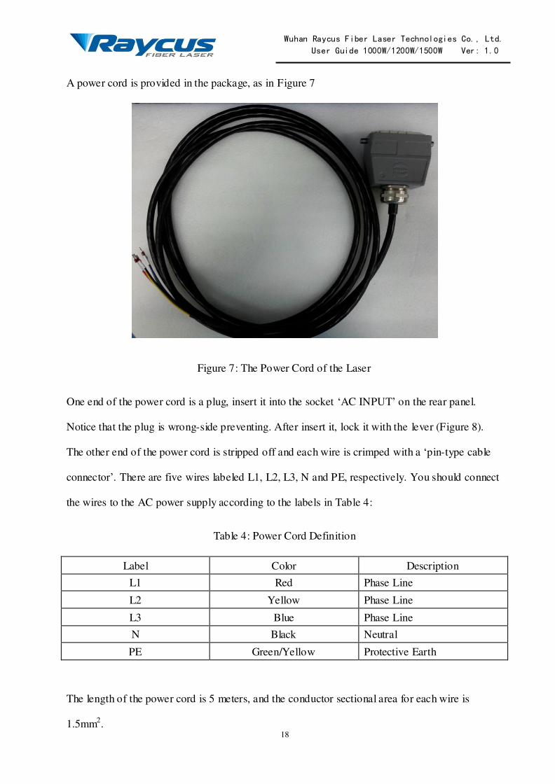
A power cord is provided in the package, as in Figure 7
Figure 7: The Power Cord of the Laser
One end of the power cord is a plug, insert it into the socket „AC INPUT‟ on the rear panel.
Notice that the plug is wrong-side preventing. After insert it, lock it with the lever (Figure 8).
The other end of the power cord is stripped off and each wire is crimped with a „pin-type cable
connector‟. There are five wires labeled L1, L2, L3, N and PE, respectively. You should connect
the wires to the AC power supply according to the labels in Table 4:
Table 4: Power Cord Definition
Label Color Description
L1 Red Phase Line
L2 Yellow Phase Line
L3 Blue Phase Line
N Black Neutral
PE Green/Yellow Protective Earth
The length of the power cord is 5 meters, and the conductor sectional area for each wire is
1.5mm2.

Wuhan Raycus Fiber Laser Technologies Co., Ltd. User Guide 1000W/1200W/1500W Ver: 1.0
19
1. Protective cap; 2. Lever; 3. Plug; 4. Socket
Figure 8: Lock the Plug of the Power Cord with the Lever
4.4 Control Wire Definitions
All the control signals are integrated in the „INTERFACE‟ on the rear panel (Figure 5).
We provide a cable for the „INTERFACE‟, as shown in Figure 9

Wuhan Raycus Fiber Laser Technologies Co., Ltd. User Guide 1000W/1200W/1500W Ver: 1.0
20
Figure 9: The Cable for the INTERFACE
Insert the plug into the „INTERFACE‟, and lock it with the lever, as shown in Figure 10, when
you are ready to use the product.

Wuhan Raycus Fiber Laser Technologies Co., Ltd. User Guide 1000W/1200W/1500W Ver: 1.0
21
1. Protective cap; 2. Lever; 3. Plug; 4. Socket
Figure 10: Lock the Plug of the Cable for „INTERFACE‟ with the lever
The control cable for the „INTERFACE‟ is actually 6 cables, they are for different purpose.
The control wire definitions are in the following table.
Wuhan Raycus Fiber Laser Technologies Co., Ltd. User Guide 1000W/1200W/1500W Ver: 1.0
22
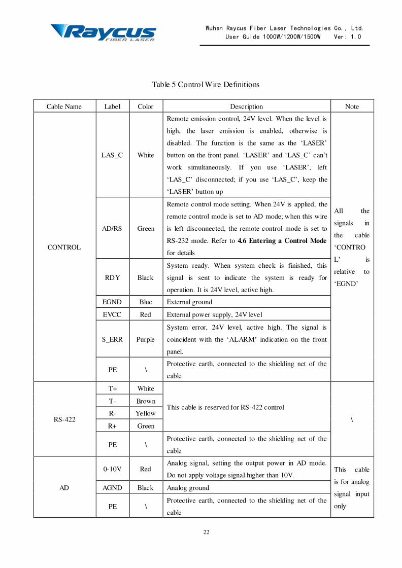
Table 5 Control Wire Definitions
Cable Name Label Color Description Note
CONTROL
LAS_C White
Remote emission control, 24V level. When the level is
high, the laser emission is enabled, otherwise is
disabled. The function is the same as the „LASER‟
button on the front panel. „LASER‟ and „LAS_C‟ can‟t
work simultaneously. If you use „LASER‟, left
„LAS_C‟ disconnected; if you use „LAS_C‟, keep the
„LASER‟ button up
All the
signals in
the cable
„CONTRO
L‟ is
relative to
„EGND‟
AD/RS Green
Remote control mode setting. When 24V is applied, the
remote control mode is set to AD mode; when this wire
is left disconnected, the remote control mode is set to
RS-232 mode. Refer to 4.6 Entering a Control Mode
for details
RDY Black
System ready. When system check is finished, this
signal is sent to indicate the system is ready for
operation. It is 24V level, active high.
EGND Blue External ground
EVCC Red External power supply, 24V level
S_ERR Purple
System error, 24V level, active high. The signal is
coincident with the „ALARM‟ indication on the front
panel.
PE \ Protective earth, connected to the shielding net of the
cable
RS-422
T+ White
This cable is reserved for RS-422 control
\
T- Brown
R- Yellow
R+ Green
PE \ Protective earth, connected to the shielding net of the
cable
AD
0-10V Red Analog signal, setting the output power in AD mode.
Do not apply voltage signal higher than 10V. This cable
is for analog
signal input
only
AGND Black Analog ground
PE \ Protective earth, connected to the shielding net of the
cable
Wuhan Raycus Fiber Laser Technologies Co., Ltd. User Guide 1000W/1200W/1500W Ver: 1.0
23
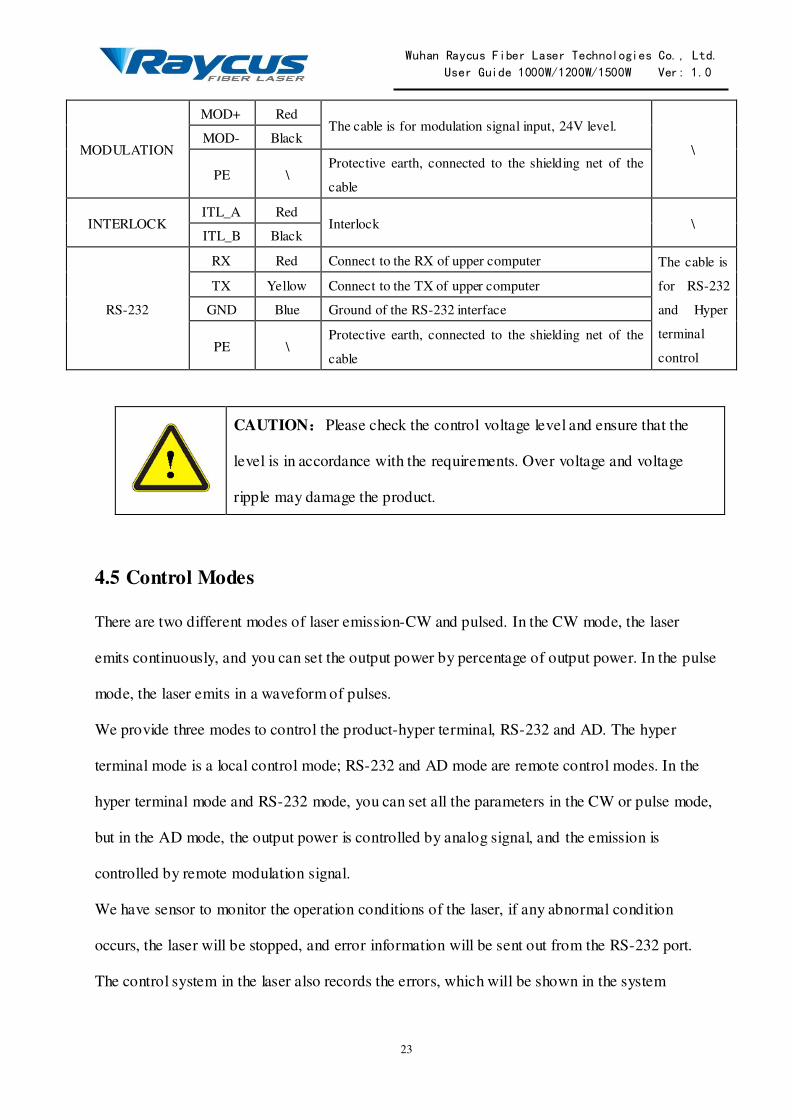
MODULATION
MOD+ Red The cable is for modulation signal input, 24V level.
\ MOD- Black
PE \ Protective earth, connected to the shielding net of the
cable
INTERLOCK ITL_A Red
Interlock \ ITL_B Black
RS-232
RX Red Connect to the RX of upper computer The cable is
for RS-232
and Hyper
terminal
control
TX Yellow Connect to the TX of upper computer
GND Blue Ground of the RS-232 interface
PE \ Protective earth, connected to the shielding net of the
cable
CAUTION:Please check the control voltage level and ensure that the
level is in accordance with the requirements. Over voltage and voltage
ripple may damage the product.
4.5 Control Modes
There are two different modes of laser emission-CW and pulsed. In the CW mode, the laser
emits continuously, and you can set the output power by percentage of output power. In the pulse
mode, the laser emits in a waveform of pulses.
We provide three modes to control the product-hyper terminal, RS-232 and AD. The hyper
terminal mode is a local control mode; RS-232 and AD mode are remote control modes. In the
hyper terminal mode and RS-232 mode, you can set all the parameters in the CW or pulse mode,
but in the AD mode, the output power is controlled by analog signal, and the emission is
controlled by remote modulation signal.
We have sensor to monitor the operation conditions of the laser, if any abnormal condition
occurs, the laser will be stopped, and error information will be sent out from the RS-232 port.
The control system in the laser also records the errors, which will be shown in the system

Wuhan Raycus Fiber Laser Technologies Co., Ltd. User Guide 1000W/1200W/1500W Ver: 1.0
24
self-check in hyper terminal mode. Refer to 4.7.3 Operation in Hyper Terminal Mode for
details.
4.6 Entering a Control Mode
The following diagram shows the process of entering a certain control mode.
Figure 11: The Process of Entering Different Control Modes
You can see that, if you want to enter hyper terminal mode, you must turn the key to the „ON‟
position; if you want to enter a remote control mode, you must turn the key to the „REM‟
position. Whether you enter AD mode or RS-232 mode depends on 24V is applied to PIN7 and
PIN9 of the „CTRL-INTERFACE‟ or not.
4.7 Hyper Terminal Mode
Hyper terminal mode is a local control mode. Hyper terminal is a communication tool in
Windows system, so make sure your PC operation system is Windows. In hyper terminal mode,
operation parameters can be set, and errors can be displayed and cleared.
Connect power
supply and interfaces
Switch on the
laser
Switch on the
laser
24V is applied between
AD/RS and EGND of the
‘CONRTOL’ cable
AD/RS of the
‘CONRTOL’ cable
is left disconnected
Turn the switch to the
‘REM’ position
Turn the switch to the
‘ON’ position
Turn the switch to the
‘REM’ position
Turn the switch to the
‘ON’ position
AD mode Hyper
terminal
mode
Hyper
terminal
mode
RS-232
mode

Wuhan Raycus Fiber Laser Technologies Co., Ltd. User Guide 1000W/1200W/1500W Ver: 1.0
25
4.7.1 Wiring in Hyper Terminal Mode
Figure 12: Wiring in Hyper Terminal Mode
The wiring in hyper terminal mode is in Figure 12. The „CONTROL‟ cable is for different
purposes. „LAS_C‟ is for remote emission control, „AD/RS‟ is for control mode setting, „RDY‟
is a flag for system self-check accomplishment. „S_ERR‟ is for system error report. „EVCC‟ is
24V external power supply. All the signals in the „CONTROL‟ cable are 24V level, and are
relative to „EGND‟. If you don‟t use remote emission control, left „LAS_C‟ disconnected. The
„MODULATION‟ cable need to be connected when the laser emission is controlled by remote
modulation signal, otherwise can be left disconnected. The „RX‟ and „TX‟ of the „RS-232‟ cable
should be connected to the „RX‟ and „TX‟ of the PC, respectively. „AD‟ and „RS-422‟ should be
INTERFACE
AC INPUT
ADLeft Disconnected
MODULATIONModulation Signal
INTERLOCKITL_A
ITL_B Shorted
COM of PCRS-232
RS-422Left Disconnected
L1
L2
L3
N
PE
Three Phase
AC Power
Supply(With
Neutral)
RX
TX
GND
Left DisconnectedCONTROL
LAS_C
AD/RS
RDY
EGND
EVCC
Emission Control Signal
System Ready
External Ground
External Power Supply
S_ERRSystem Error

Wuhan Raycus Fiber Laser Technologies Co., Ltd. User Guide 1000W/1200W/1500W Ver: 1.0
26
left disconnected. The PE of the cable for „INTERFACE‟ is not shown in Figure 12, but we
recommend you to connect all the PE wires to the protective earth.
4.7.2 Hyper Terminal Setup
Follow the instructions to setup hyper terminal:
(1) In Windows system, click as follows: START→Accessories→Communication→ Hyper
Terminal;
(2) A dialog will pop up, to recommend Hyper Terminal as the default telnet program, choose
„Yes‟;
(3) Hyper terminal will start, type in any name for „New Connection‟, then click „OK‟;
(4) Choose the COM you connected with the RS-232 cable, then click „OK‟;
(5) Set up communication protocol: Baud rate-9600, Data Bits-8, Parity-None, Stop bits-1, Flow
Control-None. Then click „OK‟;
Now the hyper terminal setup is finished.
4.7.3 Operation in Hyper Terminal Mode
Before you start the laser, check the wiring, cooling connection and the most important, the
delivery cable and optic output terminal are OK. Make sure that the interlock is shorted, and the
laser emission button is up (emission disabled). Then start the chiller.
Turn the key to the „ON‟ position to start the laser, and the system start self-check. If the process
of system self-check is normal, the following information will be displayed in the hyper
terminal:
Welcome to use Raycus fiber laser
The Model is RFL-CXXX/X/X/X(the model name of the laser)
Checking RS-232 connection............................
RS-232 connected..........................................
System is doing self-check, please wait........
Wuhan Raycus Fiber Laser Technologies Co., Ltd. User Guide 1000W/1200W/1500W Ver: 1.0
27
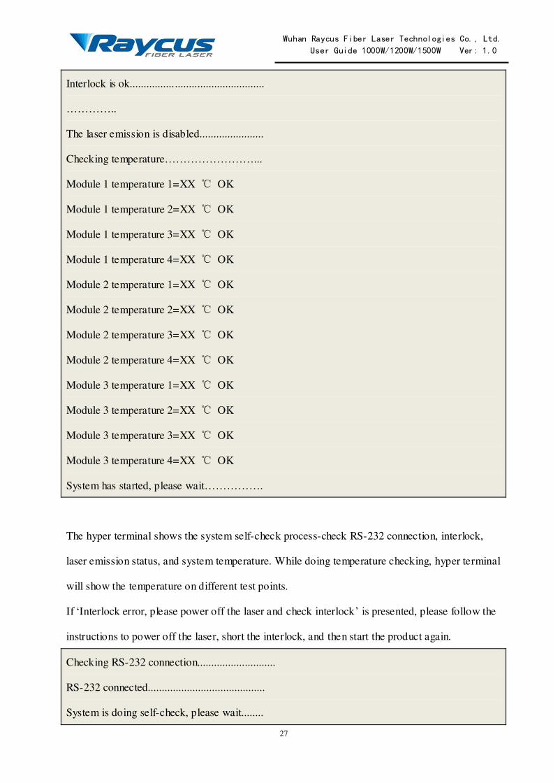
Interlock is ok................................................
…………..
The laser emission is disabled.......................
Checking temperature……………………...
Module 1 temperature 1=XX ℃ OK
Module 1 temperature 2=XX ℃ OK
Module 1 temperature 3=XX ℃ OK
Module 1 temperature 4=XX ℃ OK
Module 2 temperature 1=XX ℃ OK
Module 2 temperature 2=XX ℃ OK
Module 2 temperature 3=XX ℃ OK
Module 2 temperature 4=XX ℃ OK
Module 3 temperature 1=XX ℃ OK
Module 3 temperature 2=XX ℃ OK
Module 3 temperature 3=XX ℃ OK
Module 3 temperature 4=XX ℃ OK
System has started, please wait…………….
The hyper terminal shows the system self-check process-check RS-232 connection, interlock,
laser emission status, and system temperature. While doing temperature checking, hyper terminal
will show the temperature on different test points.
If „Interlock error, please power off the laser and check interlock‟ is presented, please follow the
instructions to power off the laser, short the interlock, and then start the product again.
Checking RS-232 connection............................
RS-232 connected..........................................
System is doing self-check, please wait........

Wuhan Raycus Fiber Laser Technologies Co., Ltd. User Guide 1000W/1200W/1500W Ver: 1.0
28
Interlock error, please power off the laser and check interlock
If „Laser emission is not disabled, please power off the laser and check if LASER button on the
front panel is pressed down‟ is present in the self-check process, please follow the instructions to
check the laser emission button on the front panel, press it to release, and then restart the product
with the key. Laser emission must be disabled on system start-up.
Checking RS-232 connection............................
RS-232 connected..........................................
System is doing self-check, please wait........
Interlock is ok................................................
Laser emission is not disabled, please power off the laser and check if LASER button on the
front panel is pressed down….......................
When „System has started, please wait…………..‟ is presented, self-check is passed, „RDY‟
signal is sent, and error records will be presented, followed by an instruction to press „U‟ on the
keyboard in 3 seconds.
Err1 record: 0
->Module 1 T1 High temperature record: 0
->Module 1 T1 Low temperature record: 0
->Module 1 T2 High temperature record: 0
->Module 1 T2 Low temperature record: 0
->Module 1 T3 High temperature record: 0
->Module 1 T3 Low temperature record: 0
->Module 1 T4 High temperature record: 0
->Module 1 T4 Low temperature record: 0
->Module 2 T1 High temperature record: 0

Wuhan Raycus Fiber Laser Technologies Co., Ltd. User Guide 1000W/1200W/1500W Ver: 1.0
29
->Module 2 T1 Low temperature record: 0
->Module 2 T2 High temperature record: 0
->Module 2 T2 Low temperature record: 0
->Module 2 T3 High temperature record: 0
->Module 2 T3 Low temperature record: 0
->Module 2 T4 High temperature record: 0
->Module 2 T4 Low temperature record: 0
->Module 3 T1 High temperature record: 0
->Module 3 T1 Low temperature record: 0
->Module 3 T2 High temperature record: 0
->Module 3 T2 Low temperature record: 0
->Module 3 T3 High temperature record: 0
->Module 3 T3 Low temperature record: 0
->Module 3 T4 High temperature record: 0
->Module 1 T4 Low temperature record: 0
Err2 record: 0
Err3 record: 0
Err4 record: 0
->Module 1 Err4 record: 0
->Module 2 Err4 record: 0
->Module 3 Err4 record: 0
Err5 record: 0
Err6 record: 0
-> Module 1 Err6 record: 0
-> Module 2 Err6 record: 0
-> Module 3 Err6 record: 0
Wuhan Raycus Fiber Laser Technologies Co., Ltd. User Guide 1000W/1200W/1500W Ver: 1.0
30
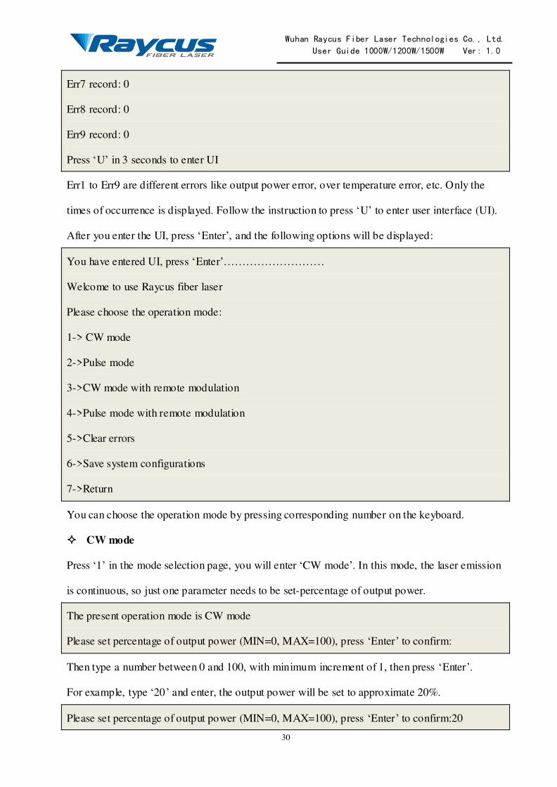
Err7 record: 0
Err8 record: 0
Err9 record: 0
Press „U‟ in 3 seconds to enter UI
Err1 to Err9 are different errors like output power error, over temperature error, etc. Only the
times of occurrence is displayed. Follow the instruction to press „U‟ to enter user interface (UI).
After you enter the UI, press „Enter‟, and the following options will be displayed:
You have entered UI, press „Enter‟………………………
Welcome to use Raycus fiber laser
Please choose the operation mode:
1-> CW mode
2->Pulse mode
3->CW mode with remote modulation
4->Pulse mode with remote modulation
5->Clear errors
6->Save system configurations
7->Return
You can choose the operation mode by pressing corresponding number on the keyboard.
CW mode
Press „1‟ in the mode selection page, you will enter „CW mode‟. In this mode, the laser emission
is continuous, so just one parameter needs to be set-percentage of output power.
The present operation mode is CW mode
Please set percentage of output power (MIN=0, MAX=100), press „Enter‟ to confirm:
Then type a number between 0 and 100, with minimum increment of 1, then press „Enter‟.
For example, type „20‟ and enter, the output power will be set to approximate 20%.
Please set percentage of output power (MIN=0, MAX=100), press „Enter‟ to confirm:20
Wuhan Raycus Fiber Laser Technologies Co., Ltd. User Guide 1000W/1200W/1500W Ver: 1.0
31
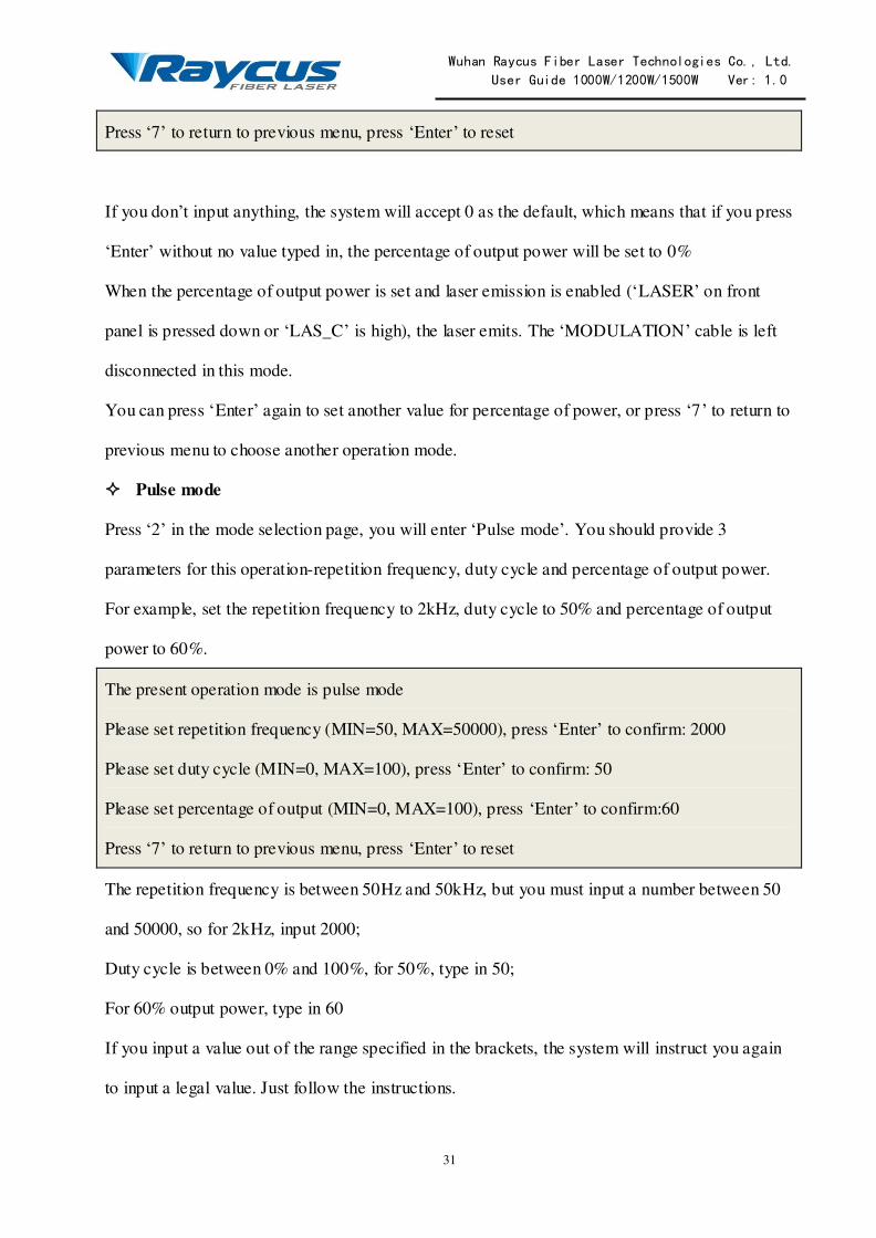
Press „7‟ to return to previous menu, press „Enter‟ to reset
If you don‟t input anything, the system will accept 0 as the default, which means that if you press
„Enter‟ without no value typed in, the percentage of output power will be set to 0%
When the percentage of output power is set and laser emission is enabled („LASER‟ on front
panel is pressed down or „LAS_C‟ is high), the laser emits. The „MODULATION‟ cable is left
disconnected in this mode.
You can press „Enter‟ again to set another value for percentage of power, or press „7‟ to return to
previous menu to choose another operation mode.
Pulse mode
Press „2‟ in the mode selection page, you will enter „Pulse mode‟. You should provide 3
parameters for this operation-repetition frequency, duty cycle and percentage of output power.
For example, set the repetition frequency to 2kHz, duty cycle to 50% and percentage of output
power to 60%.
The present operation mode is pulse mode
Please set repetition frequency (MIN=50, MAX=50000), press „Enter‟ to confirm: 2000
Please set duty cycle (MIN=0, MAX=100), press „Enter‟ to confirm: 50
Please set percentage of output (MIN=0, MAX=100), press „Enter‟ to confirm:60
Press „7‟ to return to previous menu, press „Enter‟ to reset
The repetition frequency is between 50Hz and 50kHz, but you must input a number between 50
and 50000, so for 2kHz, input 2000;
Duty cycle is between 0% and 100%, for 50%, type in 50;
For 60% output power, type in 60
If you input a value out of the range specified in the brackets, the system will instruct you again
to input a legal value. Just follow the instructions.

Wuhan Raycus Fiber Laser Technologies Co., Ltd. User Guide 1000W/1200W/1500W Ver: 1.0
32
When the parameters are set and laser emission is enabled („LASER‟ on front panel is pressed
down or „LAS_C‟ is high), the laser emits sequence of pulses you have customized. The
„MODULATION‟ cable is also left disconnected in this mode.
CW mode with remote modulation and Pulse mode with remote modulation
Press „3‟ in the mode selection page to enter „CW mode with remote modulation‟, and press „4‟
to enter „Pulse mode with remote modulation‟. In these 2 operation modes, the parameter
settings are no different from „CW mode‟ and „Pulse mode‟. Only one more emission condition
is added-remote modulation signal. So you must connect the „MODULATION‟ cable to remote
modulation signal. Notice that the modulation signal is 24V level, and active high.
When the parameters are set, laser emission is enabled („LASER‟ on front panel is pressed down
or remote emission control is sent from „LAS_C‟), and the remote modulation signal inputs from
„MODULATION‟, the laser emits.
Clear errors
Press „5‟ in the mode selection page will clear error records. Then press „7‟ to return.
Error records are cleared
Press „7‟ to return to previous menu
Save system configurations
This operation is for Raycus personnel only.
4.8 RS-232 Mode
RS-232 mode is a remote control mode. In this mode, we have a protocol for communication
between the laser and the upper computer, and you can set emission parameters and return errors.
Notice that the „LASER‟ button or „LAS_C‟ is of no use in this mode, but make sure to keep the
button up and left „LAS_C‟ disconnected.

Wuhan Raycus Fiber Laser Technologies Co., Ltd. User Guide 1000W/1200W/1500W Ver: 1.0
33
4.8.1 Wiring in RS-232 Mode
Figure 13: Wiring in RS-232 Mode
The wiring in RS-232 mode is similar to the wiring in hyper terminal mode. The differences are:
you have to connect the „MODULATION‟ cable, and „LAS_C‟ must be left disconnected.
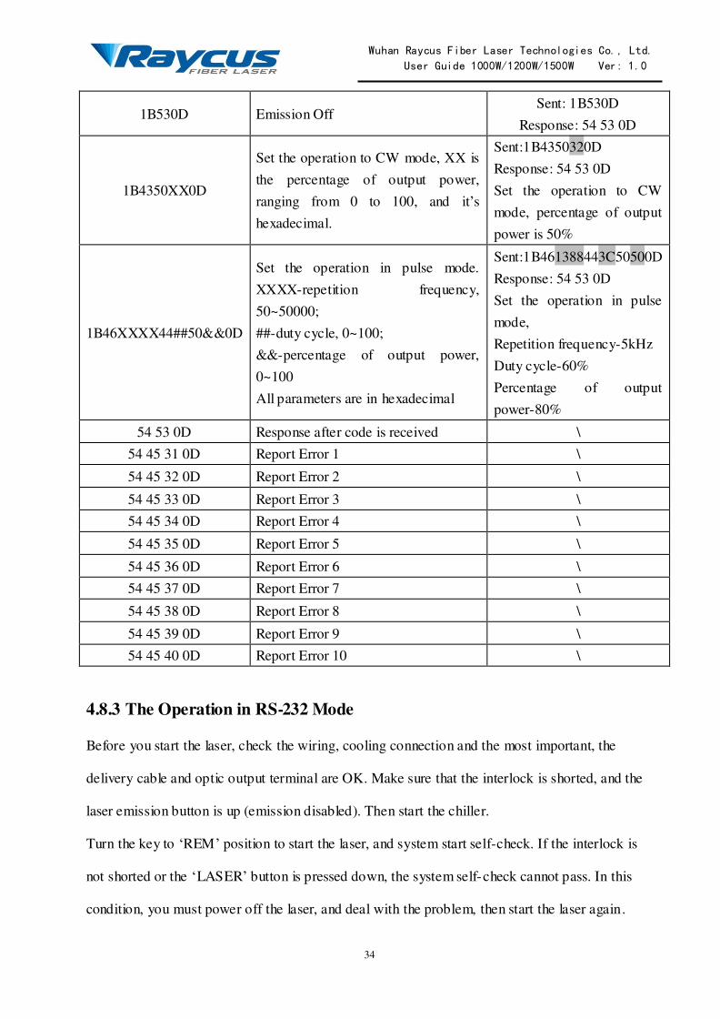
4.8.2 The Communication Protocol
The protocol is presented in the table below:
Table 6: The Communication Protocol for RS-232 Mode
Code Description Example
1B4F0D Emission On Sent: 1B4F0D
Response: 54 53 0D
INTERFACE
AC INPUT
Left Disconnected
ADLeft Disconnected
MODULATIONModulation Signal
INTERLOCKITL_A
ITL_B Shorted
COM of PCRS-232
RS-422Left Disconnected
L1
L2
L3
N
PE
Three Phase
AC Power
Supply(With
Neutral)
RX
TX
GND
CONTROL
LAS_C
AD/RS
RDY
EGND
EVCC
System Ready
External Ground
External Power Supply
S_ERRSystem Error
Left Disconnected
Wuhan Raycus Fiber Laser Technologies Co., Ltd. User Guide 1000W/1200W/1500W Ver: 1.0
34
1B530D Emission Off Sent: 1B530D
Response: 54 53 0D
1B4350XX0D
Set the operation to CW mode, XX is
the percentage of output power,
ranging from 0 to 100, and it‟s
hexadecimal.
Sent:1B4350320D
Response: 54 53 0D
Set the operation to CW
mode, percentage of output
power is 50%
1B46XXXX44##50&&0D
Set the operation in pulse mode.
XXXX-repetition frequency,
50~50000;
##-duty cycle, 0~100;
&&-percentage of output power,
0~100
All parameters are in hexadecimal
Sent:1B461388443C50500D
Response: 54 53 0D
Set the operation in pulse
mode,
Repetition frequency-5kHz
Duty cycle-60%
Percentage of output
power-80%
54 53 0D Response after code is received \
54 45 31 0D Report Error 1 \
54 45 32 0D Report Error 2 \
54 45 33 0D Report Error 3 \
54 45 34 0D Report Error 4 \
54 45 35 0D Report Error 5 \
54 45 36 0D Report Error 6 \
54 45 37 0D Report Error 7 \
54 45 38 0D Report Error 8 \
54 45 39 0D Report Error 9 \
54 45 40 0D Report Error 10 \
4.8.3 The Operation in RS-232 Mode
Before you start the laser, check the wiring, cooling connection and the most important, the
delivery cable and optic output terminal are OK. Make sure that the interlock is shorted, and the
laser emission button is up (emission disabled). Then start the chiller.
Turn the key to „REM‟ position to start the laser, and system start self-check. If the interlock is
not shorted or the „LASER‟ button is pressed down, the system self-check cannot pass. In this
condition, you must power off the laser, and deal with the problem, then start the laser again.

Wuhan Raycus Fiber Laser Technologies Co., Ltd. User Guide 1000W/1200W/1500W Ver: 1.0
35
The system self-check will pass in about 30 seconds, then „RDY‟ signal will be sent. After that,
you can send codes from the upper computer. In RS-232 mode, the laser emits on conditions that
the „Emission On‟ code (1B4F0D) is received, operation parameters are set and remote
modulation signal inputs from the „MODULATION‟ cable.
In RS-232 mode, you can still use hyper terminal to monitor the status of the laser. All you have
to do is to start windows hyper terminal, and configure it as stated in 4.7.2 Hyper Terminal Setup.
But you can‟t set operation parameters from hyper terminal when the control mode is RS-232.
4.9 AD Mode
AD mode is also remote control mode. In AD mode, the output power is set by analog signal,
and pulse mode is not available in this control mode.
4.9.1 Wiring in AD Mode
INTERFACE
AC INPUT
CONTROL
LAS_C
AD/RS
RDY
EGND
EVCC
Emission Control Signal
System Ready
External Ground
External Power Supply
AD
MODULATIONModulation Signal
INTERLOCKITL_A
ITL_B Shorted
COM of PCRS-232
RS-422Left Disconnected
L1
L2
L3
N
PE
Three Phase
AC Power
Supply(With
Neutral)
RX
TX
GND
24V
0-10V
AGND
Analog
Signal
S_ERRSystem Error

Wuhan Raycus Fiber Laser Technologies Co., Ltd. User Guide 1000W/1200W/1500W Ver: 1.0
36
Figure 14: Wiring in AD Mode
The wiring in AD mode is shown in Figure 14. There is an important difference in the
„CONTROL‟ cable connection - 24V must be applied between „AD/RS‟ and „EGND‟. If you
don‟t use remote emission control, left „LAS_C‟ disconnected. The „MODULATION‟ and
„INTERLOCK‟ cable connection are same as wiring in hyper terminal and RS-232 mode. If you
want to monitor the system status in hyper terminal, you can still connect the „RS-232‟ cable to
PC. The analog signal is input from „AD‟ cable.
4.9.2 The Operation in AD Mode
Before you start the laser, check the wiring, cooling connection and the most important, the
delivery cable and optic output terminal are OK. Make sure that the interlock is shorted, and the
laser emission button is up (emission disabled). Then start the chiller.
Turn the key to „REM‟ position to start the laser, and system start self-check. If the interlock is
not shorted or the „LASER‟ button is pressed down, the system self-check cannot pass. In this
condition, you must power off the laser, and deal with the problem, then start the laser again.
The system self-check will pass in about 30 seconds, then „RDY‟ signal will be sent. After that,
the laser is ready to receive analog signal, and you can press down „LASER‟ button to enable the
laser emission.
In AD mode, the laser emits on conditions that „LASER‟ button is pressed down or „LAS_C‟ is
high, analog signal is received and remote modulation signal inputs from the „MODULATION‟
cable.
You can still use hyper terminal to monitor the status of the laser. All you have to do is to
connect the „RS-232‟ cable to your PC, then start windows hyper terminal, and configure it as
stated in 4.7.2 Hyper Terminal Setup. But you can‟t set operation parameters from hyper
terminal when the control mode is AD.

Wuhan Raycus Fiber Laser Technologies Co., Ltd. User Guide 1000W/1200W/1500W Ver: 1.0
37
CAUTION:Please ensure that the analog signal DO NOT exceed 10V, or
product may be damaged.

Wuhan Raycus Fiber Laser Technologies Co., Ltd. User Guide 1000W/1200W/1500W Ver: 1.0
38
5 Warranty, Return and Maintenance
5.1 General Warranty
Raycus warrants that all Raycus fiber laser products are comformed to applicable product
specifications under normal use and are free from defects in materials and workmanship. The
warranties start on the date of shipment from Raycus for a period of time as set forth in the
applicable purchase contracts or product specifications. Raycus has the right to choose to repair
or replace any product that proves to be defective in materials and workmanship selectively
during the warranty period. Only products with particular defects are under warranty. Raycus
reserves the right to issue a credit note for any defective products produced in normal conditions.
5.2 Limitations of Warranty
The warranty does not cover the maintenance or reimbursement of our product of which the
problem results from tampering, disassembling, misuse, accident, modification, unsuitable
physical or operating environment, improper maintenance, damages due to excessive use or not
following the instructions caused by those who are not from Raycus. Customer has the
responsibility to understand and follow this instruction to use the device. Any damage caused by
fault operating is not warranted. Accessories and fiber connectors are excluded from this
warranty.
According to the warranty, client should write to us within 31days after the defect is d iscovered.
This warranty does not involve any other party, including specified buyer, end-user or customer
and any parts, equipment or other products produced by other companies.
WARNING: It is the customer‟s responsibility to understand and follow operating instructions in this User Guide and specifications prior to
operation-failure to do so may void this warranty. Accessories and fiber
connectors are not covered by this warranty.
5.3 Service and Repair
Do not open the device. There are no user serviceable parts, equipment or assemblies for
user in this product. All service and maintenance shall be performed by qualified Raycus
personnel.

Wuhan Raycus Fiber Laser Technologies Co., Ltd. User Guide 1000W/1200W/1500W Ver: 1.0
39
Please contact Raycus as soon as possible when problems under warranty about maintenance
happened to the product.
The product returned with permission should be placed in a suitable container.
If any damage happened to the product, please notify the carrier in document immediately.
We reserve the right to make changes in design or constructions of any of our products at
any time without incurring any obligation to make changes or install the same on units
previously purchased.
All the items about warranty and service above provided by Raycus are for uses ’ reference;
formal contents about warranty and service are subject to the contract.
© 2014 Wuhan Raycus Fiber Laser technologies Co. Ltd, All Rights Reserved.


