8
Multi-stage steam jet vacuum systems operating in Alkaline Closed Loop (ACL)
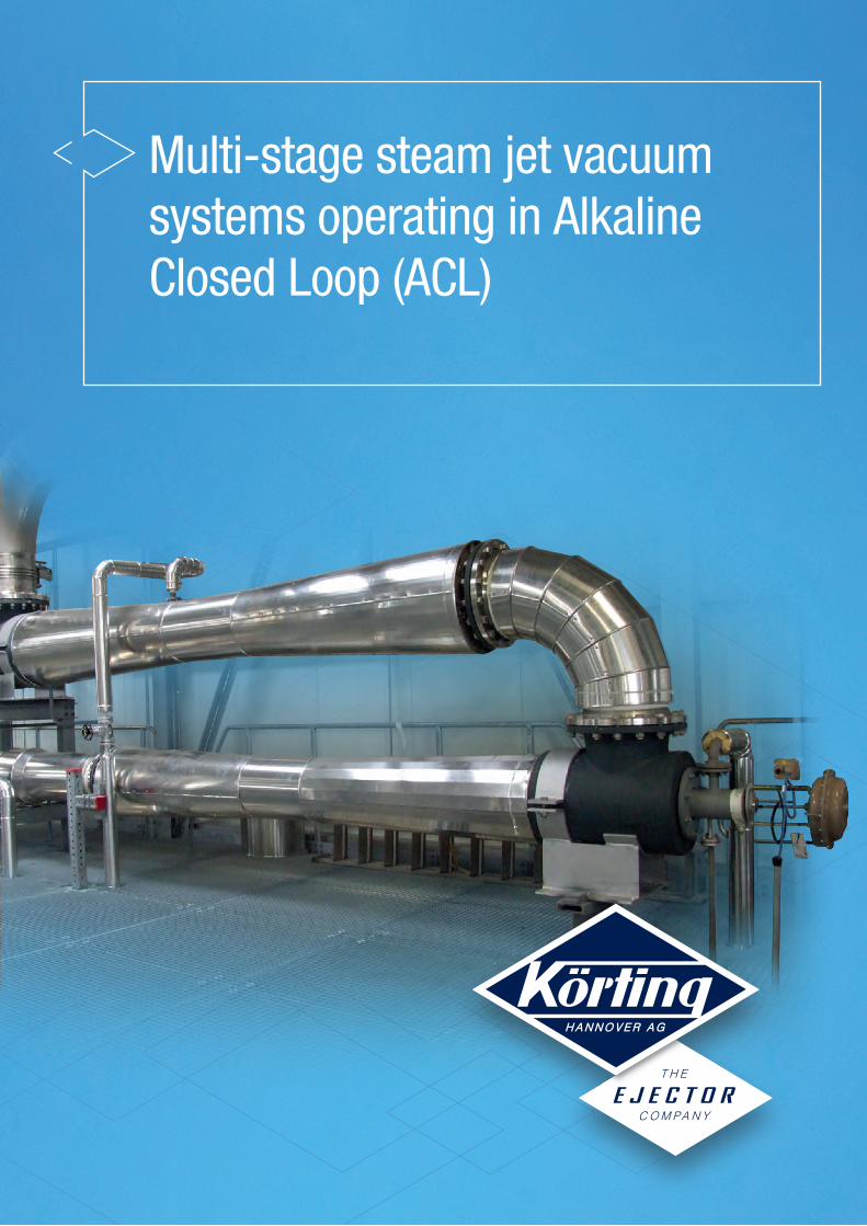
Multi-stage steam jet vacuum systems operating in Alkaline Closed Loop (ACL)
p H
5
1
23
4
17
11
16
8
14
12
10
13
9
15
16
7
6
16
11m
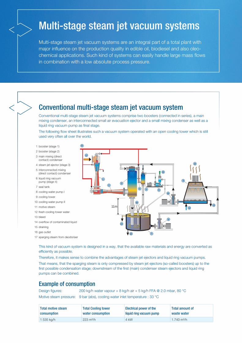
Multi-stage steam jet vacuum systemsMulti-stage steam jet vacuum systems are an integral part of a total plant with major influence on the production quality in edible oil, biodiesel and also oleo-chemical applications. Such kind of systems can easily handle large mass flows in combination with a low absolute process pressure.
1 booster (stage 1)
2 booster (stage 2)
3 main mixing (direct contact) condenser
4 steam jet ejector (stage 3)
5 interconnected mixing (direct contact) condenser
6 liquid ring vacuum pump (stage 4)
7 seal tank
8 cooling water pump I
9 cooling tower
10 cooling water pump II
11 motive steam
12 fresh cooling tower water
13 bleed
14 overflow of contaminated liquid
15 draining
16 gas outlet
17 sparging steam from deodoriser
Conventional multi-stage steam jet vacuum systemConventional multi-stage steam jet vacuum systems comprise two boosters (connected in series), a main mixing condenser, an interconnected small air evacuation ejector and a small mixing condenser as well as a liquid ring vacuum pump as final stage.
The following flow sheet illustrates such a vacuum system operated with an open cooling tower which is still used very often all over the world.
This kind of vacuum system is designed in a way, that the available raw materials and energy are converted as efficiently as possible.
Therefore, it makes sense to combine the advantages of steam jet ejectors and liquid ring vacuum pumps.
That means, that the sparging steam is only compressed by steam jet ejectors (so-called boosters) up to the first possible condensation stage; downstream of the first (main) condenser steam ejectors and liquid ring pumps can be combined.
Example of consumption Design figures: 200 kg/h water vapour + 8 kg/h air + 5 kg/h FFA @ 2.0 mbar, 80 °C
Motive steam pressure: 9 bar (abs), cooling water inlet temperature : 33 °C
Total motive steam consumption
Total Cooling tower water consumption
Electrical power of the liquid ring vacuum pump
Total amount of waste water
1 535 kg/h 223 m³/h 4 kW 1.740 m³/h
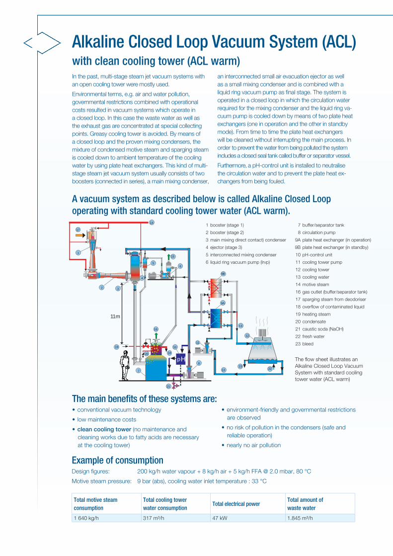
with clean cooling tower (ACL warm)
A vacuum system as described below is called Alkaline Closed Loop operating with standard cooling tower water (ACL warm).
In the past, multi-stage steam jet vacuum systems with an open cooling tower were mostly used.
Environmental terms, e.g. air and water pollution, governmental restrictions combined with operational costs resulted in vacuum systems which operate in a closed loop. In this case the waste water as well as the exhaust gas are concentrated at special collecting points. Greasy cooling tower is avoided. By means of a closed loop and the proven mixing condensers, the mixture of condensed motive steam and sparging steam is cooled down to ambient temperature of the cooling water by using plate heat exchangers. This kind of multi-stage steam jet vacuum system usually consists of two boosters (connected in series), a main mixing condenser,
an interconnected small air evacuation ejector as well as a small mixing condenser and is combined with a liquid ring vacuum pump as final stage. The system is operated in a closed loop in which the circulation water required for the mixing condenser and the liquid ring va-cuum pump is cooled down by means of two plate heat exchangers (one in operation and the other in standby mode). From time to time the plate heat exchangers will be cleaned without interrupting the main process. In order to prevent the water from being polluted the system includes a closed seal tank called buffer or separator vessel.
Furthermore, a pH-control unit is installed to neutralise the circulation water and to prevent the plate heat ex-changers from being fouled.
Example of consumption Design figures: 200 kg/h water vapour + 8 kg/h air + 5 kg/h FFA @ 2.0 mbar, 80 °C
Motive steam pressure: 9 bar (abs), cooling water inlet temperature : 33 °C
Total motive steam consumption
Total cooling tower water consumption
Total electrical power Total amount of waste water
1 640 kg/h 317 m³/h 47 kW 1.845 m³/h
pH
1
3
4
17
14
6 5
9B
9A
10
8
18
19
16
7
21
12
11
15
13 22
20
23
2
13
11m
Alkaline Closed Loop Vacuum System (ACL)
1 booster (stage 1)
2 booster (stage 2)
3 main mixing direct contact) condenser
4 ejector (stage 3)
5 interconnected mixing condenser
6 liquid ring vacuum pump (lrvp)
7 buffer/separator tank
8 circulation pump
9A plate heat exchanger (in operation)
9B plate heat exchanger (in standby)
10 pH-control unit
11 cooling tower pump
12 cooling tower
13 cooling water
14 motive steam
16 gas outlet (buffer/separator tank)
17 sparging steam from deodoriser
18 overflow of contaminated liquid
19 heating steam
20 condensate
21 caustic soda (NaOH)
22 fresh water
23 bleed
The flow sheet illustrates an Alkaline Closed Loop Vacuum System with standard cooling tower water (ACL warm)
The main benefits of these systems are:• conventional vacuum technology
• low maintenance costs
• clean cooling tower (no maintenance and cleaning works due to fatty acids are necessary at the cooling tower)
• environment-friendly and governmental restrictions are observed
• no risk of pollution in the condensers (safe and reliable operation)
• nearly no air pollution
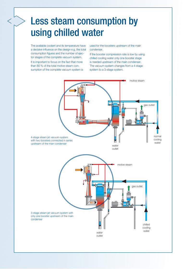
The available coolant and its temperature have a de cisive influence on the design e.g. the total consumption figures and the number of ejec-tor stages of the com plete vacuum system.
It is important to focus on the fact that more than 80 % of the total motive steam con-sumption of the complete vacuum system is
used for the boosters upstream of the main condenser.
If the booster compression rate is low by using chilled cooling water only one booster stage is needed upstream of the main condenser. The vacuum system changes from a 4-stage system to a 3-stage system.
Less steam consumption by using chilled water
4-stage steam jet vacuum system with two boosters connected in series upstream of the main condenser
motive steam
motive steam
gas outlet
gas outlet
normalcooling water
chilledcooling water
water outlet
water outlet
3-stage steam jet vacuum system with only one booster upstream of the main condenser

with clean cooling tower using chilled water (ACL cold)
The vacuum system illustrated below is called vacuum system in Alkaline Closed Loop operating with chilled water (ACL cold).
Environmental terms combined with economical factors were the main reasons for developing such multi-stage steam jet vacuum systems in order to meet future requi-rements such as sustainable and environment–friendly operation.
Such vacuum system usually consists of a 3-stage steam jet ejector group e.g. one booster (stage 1), a main mixing condenser, an interconnected small air evacuation ejector (stage 2) as well as a small mixing
condenser and is combined with a liquid ring vacuum pump (stage 3) as final stage.
The system comprises a closed seal tank called buffer or separator vessel, two plate heat exchangers (one in operation, another in standby mode) and a chilling circuit. As neutraliser caustic soda solution (NaOH) is added to the circulating water flow, which avoids too quick fouling of the heat exchangers.
By means of a refrigeration system (chilling unit), the circulating water is cooled to a temperature in the range of 5 °C to 10 °C. Therefore, the main mixing conden-ser can be operated between 13 mbar and 20 mbar instead of 50 mbar to 70 mbar in case of normal cooling water temperatures.
Due to the reduced compression ratio the system can easily operate with only one single booster as men-tioned before.
The closed loop water is cooled in plate heat ex-changers by using a suitable chiller unit. This chiller can
be cooled by means of cooling tower water or ambient air. According to the degree of fouling the plate heat exchangers are cleaned from time to time without interrupting the main process. The buffer/separator tank separates fatty material from the circulating chilled water. A pH-control unit keeps the circulation water neutralised.
Due to the higher costs of the chilling unit, the whole vacuum system is slightly more expensive compared to the systems described before.
Alkaline Closed Loop Vacuum System (ACL)
p H21
11m
1
2
17 14
8
7
19
20
6
22
10
11
1816
3
54
9B
9A
12A
24
15
1327
27
12B
13 25 26
23
5 liquid ring vacuum pump (lrvp)
6 buffer/separator tank
7 circulation pump
8 pH-control unit
9A plate heat exchanger (in operation)
9B plate heat exchanger (in standby)
10 brine pump
11 compensation vessel
12A coolant compressor (chiller) water cooled
12B coolant compressor (chiller) air cooled
1 booster (stage 1)
2 main mixing condenser
3 ejector (stage 2)
4 interconnected condenser
13 cooling water
14 motive steam
15 gas outlet (lrvp)
16 gas outlet (fat separator)
17 sparging steam from deodoriser
18 brine cycle
19 overflow of contaminated liquid
20 heating steam
21 condensate
22 caustic soda (NaOH)
23 cooling tower pump
24 cooling tower
25 fresh water
26 bleed
27 air in/out
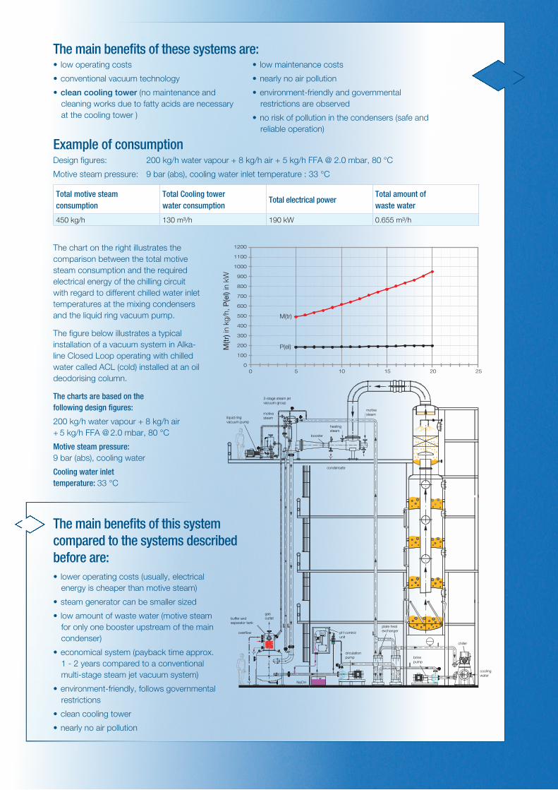
The chart on the right illustrates the comparison between the total motive steam consumption and the required electrical energy of the chilling circuit with regard to different chilled water inlet temperatures at the mixing condensers and the liquid ring vacuum pump.
Example of consumption Design figures: 200 kg/h water vapour + 8 kg/h air + 5 kg/h FFA @ 2.0 mbar, 80 °C
Motive steam pressure: 9 bar (abs), cooling water inlet temperature : 33 °C
Total motive steam consumption
Total Cooling tower water consumption
Total electrical power Total amount of waste water
450 kg/h 130 m³/h 190 kW 0.655 m³/h
The main benefits of these systems are:• low operating costs
• conventional vacuum technology
• clean cooling tower (no maintenance and cleaning works due to fatty acids are necessary at the cooling tower )
• low maintenance costs
• nearly no air pollution
• environment-friendly and governmental restrictions are observed
• no risk of pollution in the condensers (safe and reliable operation)
The main benefits of this system compared to the systems described before are:• lower operating costs (usually, electrical
energy is cheaper than motive steam)
• steam generator can be smaller sized
• low amount of waste water (motive steam for only one booster upstream of the main condenser)
• economical system (payback time approx. 1 - 2 years compared to a conventional multi-stage steam jet vacuum system)
• environment-friendly, follows governmental restrictions
• clean cooling tower
• nearly no air pollution
M(tr
) in
kg/h
, P(e
l) in
kW
P(el)
M(tr)
0
100
200
300
400
500
600
700
800
900
1000
1100
1200
0 5 10 15 20 25
8.0
cooling water
motivesteamliquid ring
vacuum pump
3-stage steam jet vacuum group
booster
heatingsteam
condensate
motivesteam
buffer and separator tank
overflow
gas outlet
NaOH
pH control unit
circulation pump
plate heat exchanger
brine pump
chiller
The figure below illustrates a typical installation of a vacuum system in Alka-line Closed Loop operating with chilled water called ACL (cold) installed at an oil deodorising column.
The charts are based on the following design figures:
200 kg/h water vapour + 8 kg/h air + 5 kg/h FFA @ 2.0 mbar, 80 °C
Motive steam pressure: 9 bar (abs), cooling water
Cooling water inlet temperature: 33 °C
Find more information about ACL and conventional vacuum systems in the Körting brochure Alkaline Closed Loop Vacuum System - Comparison with conventional vacuum systems.
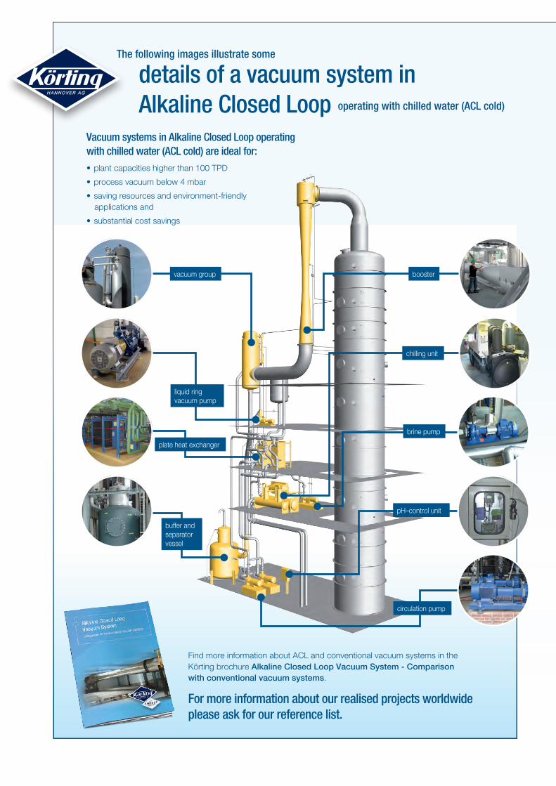
Vacuum systems in Alkaline Closed Loop operating with chilled water (ACL cold) are ideal for:• plant capacities higher than 100 TPD
• process vacuum below 4 mbar
• saving resources and environment-friendly applications and
• substantial cost savings
booster
liquid ring vacuum pump
buffer and separatorvessel
plate heat exchanger
pH–control unit
circulation pump
chilling unit
brine pump
operating with chilled water (ACL cold)
The following images illustrate some
details of a vacuum system in Alkaline Closed Loop
vacuum group
For more information about our realised projects worldwide please ask for our reference list.
sund
erdi
ek.d
e
Körting Hannover AG Badenstedter Straße 56
30453 Hannover
Germany
Tel.: +49 511 2129-253
Fax: +49 511 2129-223
www.koerting.de
221-
AC
L-E
N-1
5050
6


