+ All Categories
Home > Documents > Multi-static Active Target Tracking using an...

Multi-static Active Target Tracking using an...

Date post: 09-Jun-2018
Category:
Upload: doquynh
View: 221 times
Download: 0 times
Share this document with a friend
19
NEAR-Lab - 1 040123, lmz NEAR-Lab Northwest Electromagnetics & Acoustics Research Multi-static Active Target Tracking using an Invariance Constraint Northwest Electromagnetics & Acoustics Research Lab Electrical & Comp. Eng. Dept, Portland State Univ. Chensong He, Jorge Quijano, Lisa M. Zurk Funded by Office of Naval Research (ONR)
Transcript

NEAR-Lab - 1040123, lmz

NEAR-Lab Northwest Electromagnetics &

Acoustics Research

Multi-static Active Target Tracking using an Invariance Constraint

Northwest Electromagnetics & Acoustics Research Lab Electrical & Comp. Eng. Dept, Portland State Univ.

Chensong He, Jorge Quijano, Lisa M. Zurk

Funded by

Office of Naval Research (ONR)

NEAR-Lab - 2040123, lmz

NEAR-Lab Northwest Electromagnetics &

Acoustics Research

A significant challenge in tracking targets in multi-static active geometries is the large dimensionality and inherent uncertainty of the track hypothesis space. Traditional tracking approaches (such as Bayesian state estimators) rely on prescribed target kinematics to describe track evolution, but cannot easily incorporate the effects of shallow water multipath. The objective of the proposed research is to improve the capability and robustness of tracking algorithms for Navy multi-static active sonar systems with a physics-based processing technique that relies on the invariance principle and is incorporated into the tracker framework.

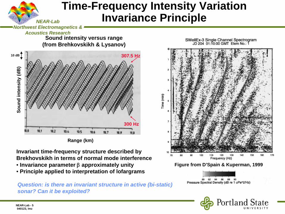
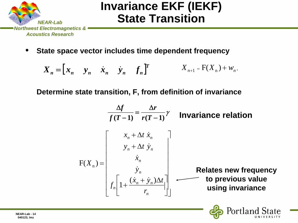
Although the invariance principle is approximately invariant to details of the ocean environment, it still provides a useful relationship between source frequency, frequency offset, target range, and target range rate. For a broadband waveform, the invariance principle suggests a method to constrain the track- hypothesis space by relating the frequency dependent signal characteristics to physically realizable target range rates. This effort is a three year effort (2005- 2008).

NEAR-Lab - 3040123, lmz

NEAR-Lab Northwest Electromagnetics &

Acoustics Research

Multi-static Sonar Systems

• Sensor network of underwater acoustic sources and receivers– Acoustic pulses illuminate and scatter from underwater targets– Received pulses provide information on time dependent range and Doppler

• Objective: Determine target track (location vs. time) from observations

• Challenges– Underwater propagation physics and bottom reverberation– Multi-dimensional solution space

)( 0tRij )( 1tRij)( 2tRkj

ith rcvr

jth src = pulse from t0

= pulse from t1= pulse from t2

= receiver

= source

= target

NEAR-Lab - 4040123, lmz

NEAR-Lab Northwest Electromagnetics &

Acoustics Research

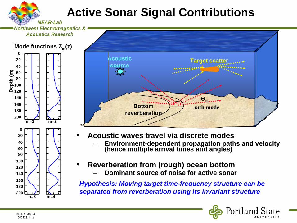
Active Sonar Signal Contributions

• Acoustic waves travel via discrete modes – Environment-dependent propagation paths and velocity

(hence multiple arrival times and angles)

• Reverberation from (rough) ocean bottom– Dominant source of noise for active sonar

Acoustic source

Target scatter

Bottom reverberation

Θm

mth mode

Mode functions Ζm (z)

Dep

th (m

)

020406080

100120140160180200

m=2m=1

m=3 m=4

020406080

100120140160180200

Hypothesis: Moving target time-frequency structure can be separated from reverberation using its invariant structure

NEAR-Lab - 5040123, lmz

NEAR-Lab Northwest Electromagnetics &

Acoustics Research

Time-Frequency Intensity Variation Invariance Principle

10 dB

Range (km)

Soun

d in

tens

ity (d

B)

Sound intensity versus range(from Brehkovskikh & Lysanov)

300 Hz

307.5 Hz

Invariant time-frequency structure described by Brekhovskikh in terms of normal mode interference• Invariance parameter β

approximately unity• Principle applied to interpretation of lofargrams

Question: is there an invariant structure in active (bi-static) sonar? Can it be exploited?

Figure from D’Spain & Kuperman, 1999

NEAR-Lab - 6040123, lmz

NEAR-Lab Northwest Electromagnetics &

Acoustics Research

Contacts2=Oil rig3=Moored tanker4=Wreck 18=Wreck 29=Wreck 3

TracksRed=East/WestBlue=DiagonalGreen=Ridge geometry

Geographic Details

Shallow Water Active Classification (SWAC) Characterization & Reduction of Active False Tracks*

Variable ValueSignal processing

Sampling rate 222 to 666 S/sPulse length 1.2 to 2 s

Broadband source

Bandwidth 70 to 400 HzCenter frequency

495 to 600 Hz

Kinematics Receiver depth 66.5 mShip’s speed 4.9 knots

Experiment specifications

*NUWC-NPT Tech Memo 04-054, 2004; Comeau & Petersen

1515 1520 1525 1530 1535

0

50

100

Sound speed profile of the channel

Dep

th(m

)

Sound Speed(m/s)

Channel specifications(135 m depth)

NEAR-Lab - 7040123, lmz

NEAR-Lab Northwest Electromagnetics &

Acoustics Research

Active Spectrograms from Malta Plateau

Note appearance of striation patterns indicative of target track

Linear

Contact 03/track 56: moored tank

Bathtub

Contact 09/track 03:Wreck=missing data

dB

from GPS

from GPS

NEAR-Lab - 8040123, lmz

NEAR-Lab Northwest Electromagnetics &

Acoustics Research

Active Sonar Simulation

• Received (bi-static) pressure:

• Environment values (bathymetry, sound speed, etc.) from NUWC– Mode functions computed with KRAKEN

• Scattering matrix: assume no mode coupling (diagonal matrix)

∑∑⎪⎭

⎪⎬⎫

⎪⎩

⎪⎨⎧

=m n

rik

rntnmnm

rik

tmsmn rk

ewzwzGrk

ewzwzCwzrpnm

21

21

),(),(),(),(),,( ψψψψ

=mnG

=),( wzmψwhere: mth mode function in the water column.=mk

=21 , rrhorizontal wavenumber of mth mode

Scattering matrix defined by the targetNormalizing constant

Source/target and target/receiver ranges

=C=),,( wzrp Pressure due to a point source of frequency ω

Source to target Target to receiver

NEAR-Lab - 9040123, lmz

NEAR-Lab Northwest Electromagnetics &

Acoustics Research

Measured versus Simulated Spectrograms for Contact 3 (Moored Tank )

Contact 03/track 56: moored tank

Spectrogram(Data)

Tim

e(m

in)

Frequency(Hz)

450 500 550

20

40

60

80

100

120

140

160

dB

-25

-20

-15

-10Spectrogram(Simulation)

Frequency(Hz)

450 500 550

20

40

60

80

100

120

140

160

-25

-20

-15

-10

-5

16 18 20 22 24 26

20

40

60

80

100

120

140

160

Range vs time

Range(km)

Simple scattering matrix: no inter- mode coupling

from GPS

NEAR-Lab - 10040123, lmz

NEAR-Lab Northwest Electromagnetics &

Acoustics Research

Contact 08/track 23:wreck

Measured versus Simulated Spectrograms for Contact 8 (Wreck )

Spectrogram(Data)

Tim

e(m

in)

Frequency(Hz)

500 600 700

10

20

30

40

50

60

70

80

90

100

dB

-25

-20

-15

-10Spectrogram(Simulation)

Frequency(Hz)

500 600 700

10

20

30

40

50

60

70

80

90

100 -25

-20

-15

-10

-5

10 12 14

10

20

30

40

50

60

70

80

90

100

Range vs time

Range(km)

Simple scattering matrix: no inter- mode coupling

from GPS

NEAR-Lab - 11040123, lmz

NEAR-Lab Northwest Electromagnetics &

Acoustics Research

Tracking using the Invariance Features

⎥⎦

⎤⎢⎣

⎡=

t

t

state vx

X

γ11

][−−

Δ=

Δtt rr

ff

= detectionTarget track

=)(tf m Frequency of striationttt rrr 21 +=

Bistatic range

⎥⎦

⎤⎢⎣

⎡+⎥

⎤⎢⎣

⎡=

bt

rt

t

t

nn

bearingrange

V

Standard Kalman Filter (SKF): Tracking based only on kinetics

Physics-based Invariance with KF: Additional time- frequency constraint imposed to decrease allowable detections

State vector Observations vector

Def.

Invariant: 1)1()( 1

1+

−=

t

tmm r

TvTfTf γ

⎥⎥⎥

⎢⎢⎢

⎡=

)(Tfvx

X

m

t

t

inv⎥⎥⎥

⎢⎢⎢

+⎥⎥⎥

⎢⎢⎢

⎡=

ft

bt

rt

m

t

t

inv

nnn

Tfbearingrange

V)(

New set of equations:

NEAR-Lab - 12040123, lmz

NEAR-Lab Northwest Electromagnetics &

Acoustics Research

Conventional Extended Kalman Filter (CEKF) for Bistatic Geometries

• State vector (position & velocity)

• Nearly constant velocity (NCV) dynamics model

[ ]Tnnnnn yxyxX =

Bistatic geometry:

r1

r2

xs ,ys

xr ,yr

xn =x(tn ), yn =y(tn )

nn tttt

t

wXX nn

−=Δ

⎥⎥⎥⎥

⎢⎢⎢⎢

⎡Δ

Δ

=

+

+

=+

1,

10000100

010001

F

F ,n1

F = state transition matrix; wn = zero mean, white Gaussian noise

NEAR-Lab - 13040123, lmz

NEAR-Lab Northwest Electromagnetics &

Acoustics Research

CEKF Observations and Measurement Model

• System measures bistatic range, r, and bearing angle w.r.t. receiver:

• Measurement model:

,)()()()(

)(2222

)( 21

rnrnsns

n

yyxxyyxx

trrr

n

ntn

−+−+−+−=

+=

[ ] ,)(),( Tnnn tmtmm r φ=, tan)( 1 ⎥

⎢⎢

⎡=

−−

rn

rnn

xxyy

rXh

n

[ ]Tnnn rZ φ=

nnn mXhZ += )(

Bistatic geometry:

r1

r2

xs ,ys

xr ,yr

xn , yn

Measurement:

Measurement noise:

NEAR-Lab - 14040123, lmz

NEAR-Lab Northwest Electromagnetics &

Acoustics Research

Invariance EKF (IEKF) State Transition

• State space vector includes time dependent frequency

Determine state transition, F, from definition of invariance

[ ]Tnnnnnn fyxyxX =

γ)1()1( −

Δ=

−Δ

Trr

Tff

,n1 )F( nn wXX +=+

⎥⎥⎥⎥⎥⎥⎥

⎢⎢⎢⎢⎢⎢⎢

⎥⎦

⎤⎢⎣

⎡ Δ++

Δ+Δ+

=

n

nnn

n

n

nn

nn

rtyxf

yx

ytyxtx

X

)(1

)F( n

Invariance relation

Relates new frequency to previous value using invariance

NEAR-Lab - 15040123, lmz

NEAR-Lab Northwest Electromagnetics &

Acoustics Research

IEKF Observations & Measurements

• System measures frequency for each pulse – For now, assume single value representing the maximum frequency– Add to measurement vector

• Measurement model becomes:

• Proceed with Kalman prediction and update as before

[ ]Tnnnn frZ φ=

⎥⎥⎥⎥

⎢⎢⎢⎢

=−

−−

n

rf

xxyy

r

Xhn

rn

n

n

1tan)(

[ ] ,)(),(),( Tnfnnn tmtmtmm r φ=

Measurement noise:

NEAR-Lab - 16040123, lmz

NEAR-Lab Northwest Electromagnetics &

Acoustics Research

Tracker Logic

• Confirm: If M contacts are associated

• Discarded: If less than M contacts are associated with N scans

• Terminated: If it’s confirmed and after K consecutive missed detections

• Validated contacts are those that satisfy the following threshold condition

( ) ( ) ( ) 21'' )1()()()1()()1()( χ<−−+−−−− iiXiCZRiCiiPiCiiXicZ ijiij

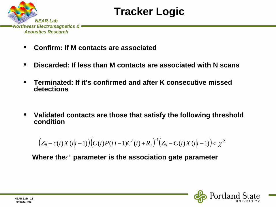
Where the parameter is the association gate parameter2χ

NEAR-Lab - 17040123, lmz

NEAR-Lab Northwest Electromagnetics &

Acoustics Research

Tracker Performance

• Addition of invariance constraint improves tracker performance– Eliminates false detections using frequency (in addition to

kinetics)– Average range error decreases 34% to 117 m (averaged over 100

realizations)

NEAR-Lab - 18040123, lmz

NEAR-Lab Northwest Electromagnetics &

Acoustics Research

Future Work

• Extend frequency measurement to spectral information– Use family of frequencies representing striations– Need transition relationship and estimation (Hough? Radon?)– Add uncertainty due to gamma

• Improve tracker formulation– Multiple tracks, increased tracker logic (track initiation,

confirmation, and elimination– More realistic reverberation environment

• Apply to real data

NEAR-Lab - 19040123, lmz

NEAR-Lab Northwest Electromagnetics &

Acoustics Research

Publications

• J. Quijano, L. M. Zurk, D. Rouseff, Demonstration of the invariance principle for monostatic active sonar, Journal of the Acoustical Society of America, May 2007, submitted for publication

• L.M. Zurk and C. He, Active target tracking using the bistatic invariance principle, invited for presentation Acoustical Society of America, Salt Lake City, Utah, June 2007

• L. M. Zurk, J. Quijano, and M. Velankar, D. Rouseff, Bistatic invariance for active sonar systems, Acoustical Society of America, Vol. 120, No. 5, p. 3221. November 2006

• J. Quijano, L. M. Zurk, D. Rouseff, Use of the invariance principle for target tracking in active sonar geometries, IEEE Oceans Conference, Boston, MA, September 2006

• L.M. Zurk, J. Quijano, D. Rouseff, Bistatic Invariance Principle for Multi- Static Active Geometries, Acoustical Society of America, Providence, RI, June 2006

• L. M. Zurk, D.Rouseff, J. Quijano, G. Greenwood, Bistatic Invariance Principle for Active Sonar Geometries, European Conference on Underwater Acousics (ECUA), Carvoviero, Portugal, June 2006


Recommended