• Engineering and technical graphics are dependent on projection methods. The two projection methods primarily used in engineering graphics are: perspective, and parallel.
• Projection theory comprises the principles used to represent graphically 3-D objects and structures on 2-D media.
• All projection theory is based on two variables: line of sight, and plane of projection.
Line of Sight
• A line of Sight (LOS) is an imaginary ray of light between the observer’s eye and an object.
• If the viewer is relatively close to the object, the LOS are not parallel.
• If the viewer is an infinite distance from the object, the LOS are parallel.
Plane of Projection
• A plane of projection (i.e. an image or picture plane) is an imaginary flat plane upon which the image is created by the lines of sight projected.
• The 3-D object is transformed into a 2-D representation (also called a projection).
Perspective Projection
Parallel Projection
Orthographic projection
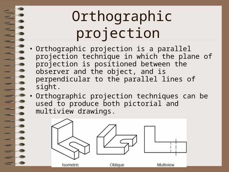
• Orthographic projection is a parallel projection technique in which the plane of projection is positioned between the observer and the object, and is perpendicular to the parallel lines of sight.
• Orthographic projection techniques can be used to produce both pictorial and multiview drawings.
Multi-view Projection
• Multiview projection is an orthographic projection for which the object is behind the plane of projection, and is oriented so only two of its dimensions are shown.
• Generally three views of an object are drawn, and the features and dimensions in each view accurately represent those of the object.
• Multiview drawings provide the most accurate description of 3D objects and structures for engineering, manufacturing, and construction requirements.
Standard Views
• The front view of an object shows the width and height dimensions. The frontal plane of projection is the plane onto which the front view of a multiview drawing is projected.
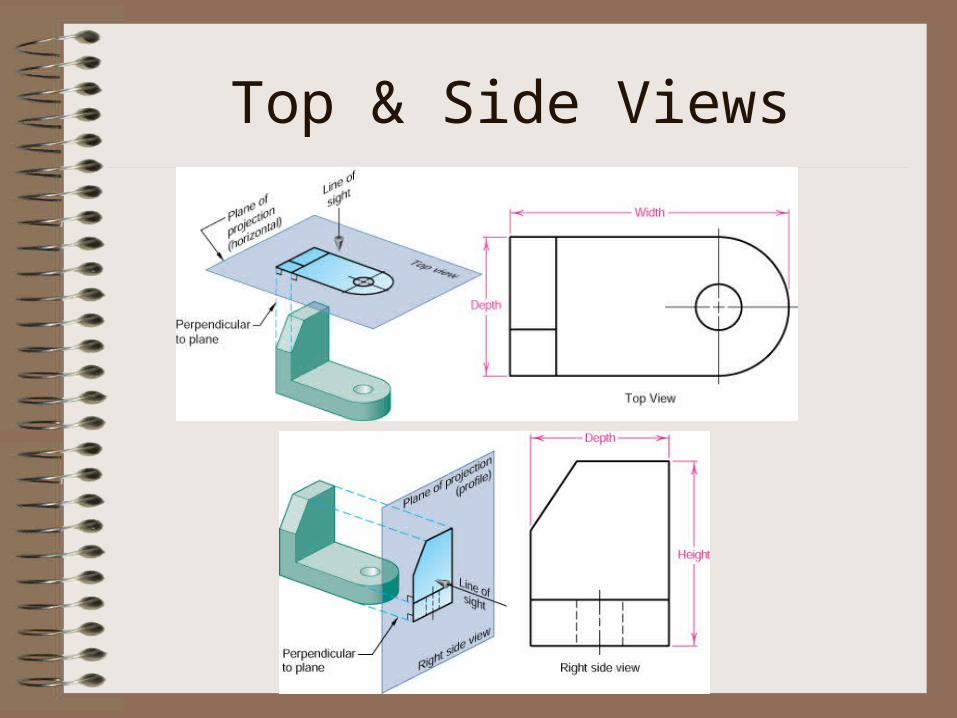
• The top view of an object shows the width and depth dimensions. The top view is projected onto the horizontal plane of projection.
• The side view of an object shows the height and depth dimensions. The side view is projected onto the profile plane of projection. The right side view is the standard side view normally used.
• The top view is always positioned above and aligned with the front view, and the right side view is always positioned to the right of and also aligned with the front view.
Front View
Top & Side Views
The Six Principle Views
• There are six principal mutually perpendicular views projected onto three mutually perpendicular projection planes.
• These views are the top, front, right, left, bottom and back.
• The width dimension is common to the front and top views. The height dimension is common to the front and side views. The depth dimension is common to the top and side views.
• The arrangement of views may vary as long as the dimension alignment is correct.
Unfolding of Glass Box
• See text figure 8.18.• Note the arrangement of views• Views are aligned• Faces are equidistance from fold lines• Dimensions can be transferred from
adjacent views via projection through miter lines.
• See figure on text page 394 and figure 8.19.
Projection Standards
• Third angle projection is the standard projection for the United States and Canada. The ANSI third angle icon is shown in text figure 8.22.
• First angle projection is the standard in Europe and Asia. The ANSI first angle icon is shown in text figure 8.22.
Alignment of Views
• Adjacent Views are two views separated by 90 degrees of viewing rotation.– The distance between views is not fixed, but may be
the same if practical.
• Related Views. Two views that are adjacent to the same view.– Distance between common features are equal.
– The two views are separated by two 90 degree rotations.
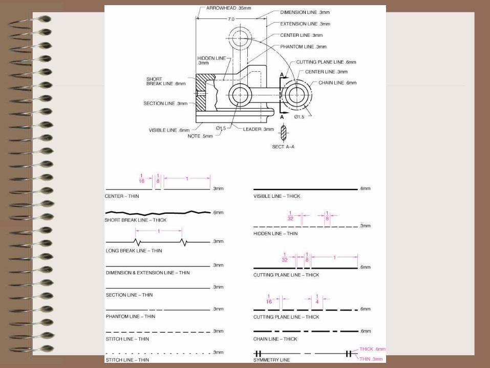
The Alphabet of Lines
• A standard produced by ASME
• Line Types– Center lines
– Break lines
– Dimension and extension lines
– Section lines
– Cutting plane lines
– Visible lines
– Hidden lines
– Phantom lines
– Stitch lines
– Chain lines
– Symmetry lines
• See definitions in the text and the examples in text figure 8.27
View Selection
• Before a multiview drawing can be created four basic decisions must be made. – Determine the best position of the object.
– Select the views that will show the least amount of hidden features.
– Determine the front view which should show the object in its natural view or assembled state, such as the front view of a car.
– Determine the minimum number of views needed to describe the object.
• Once the front view is selected, determine the other views needed to describe the object with the fewest number of lines.
Example
More Examples
Fundamental Views of Edges
• An edge, or corner, is the intersection of two planes, and is represented as a line on a multiview drawing.
• A normal edge or line, or true-length line, is an edge that is parallel to a plane of projection and thus perpendicular to the line of sight.
• An inclined edge, or line, is parallel to a plane of projection, but inclined to the adjacent planes and appears foreshortened in the adjacent views.
• Features are foreshortened when the lines of sight are not perpendicular to the feature.
• An oblique line is not parallel to any principal plane of projection, therefore, never appears in its true length or point in any of the six principal views.
Fundamental Views of Planes
• A normal or principal plane is parallel to one of the principal planes of projection, and therefore is perpendicular to the line of sight.
• A frontal plane is parallel to the front plane of projection and is true shape and size in the front and back views. (plane A)
• A horizontal plane is parallel to the horizontal plane of projection and is true shape and size in the top and bottom views. (plane B)
• A profile plane is parallel to the profile plane of projection and is true shape and size in the right and left views. (plane C)
• A inclined plane is perpendicular to one plane of projection (edge) and inclined to adjacent planes (foreshortened), and cannot be viewed in true size and shape in any of the principal views. (plane D)
• An oblique plane is oblique to all principal planes of projection. An oblique surface does not appear in its true shape or size, or as a line in any of the principal views: instead, an oblique plane always appears foreshortened in any principal view.
Multiview Representations
• A point represents a specific position in space and has no width, height, or depth. A point can represent:– The end view of a line.– The intersection of two lines.– A specific position in space.
• A plane surface will always be represented by as an edge (line) or an area (surface). Areas that are the same feature will always be similar in configuration from one view to the next, unless viewed on edge. Parallel features will be parallel in all views. Surfaces that are parallel to the lines of sight will appear as edges (lines)
• Angles are true size when they are in a normal plane.
Multiview Representations
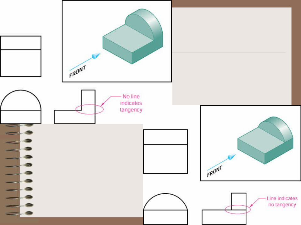
• Curved surfaces are used to round the ends of parts and to show drilled holes and cylindrical features. Only the far outside boundary, or limiting element, of a curved surface is represented in multiview drawings.
• Rounded ends or partial cylinders are represented in the circular view by arcs and by rectangles in the adjacent views. If the cylinder is tangent no change of plane is shown, but if tangency does not exist then a line is used to represent the change of plane between the partial cylinder and the prism.
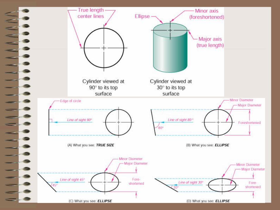
• An ellipse is used to represent a hole or circular feature that is viewed at an angle other than perpendicular or parallel.
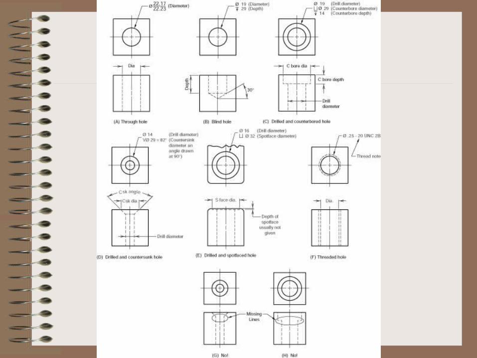
Representing Holes• A through hole is a hole that goes all the way through an
object, is represented in one view as two parallel hidden lines for the limiting elements, and is shown as a circle in the adjacent view.
• A blind hole is a hole that is not drilled all the way through the object.
• Counterbored holes are used to allow the heads of bolts to be flush or below the surface of the part.
• Countersunk holes are commonly used for flathead screws, and are represented by 45 degree lines.
• A spotface hole provides a place for heads of fasteners to rest by creating a smooth surface on cast parts.
• The representation of a threaded hole is shown. In all hole representations a line must be drawn to represent the change that occurs between the large and small diameter.
Projection Methods of Creating Ellipses and General Curves
• Identify a point on the curve in one adjacent view.
• Identify the same point in the view that is related the one used to identify the point– This can be done by projecting via a miter line if the
views are not adjacent.
• Project lines from the related views. The point is located where the projection lines intersect.
Principles of Orthographic Projection Rules
1. Alignment of Features. Every point or feature in one view must be aligned with a parallel projector in any adjacent view
2. Distances in Related Views. Distances between any two points of a feature in related views must be equal.
3. True Length & Size. Features are true length or true size when the lines of sight are perpendicular to the feature.
4. Foreshortening. Features are foreshortened when the lines of sight are not perpendicular to the feature.
Principles
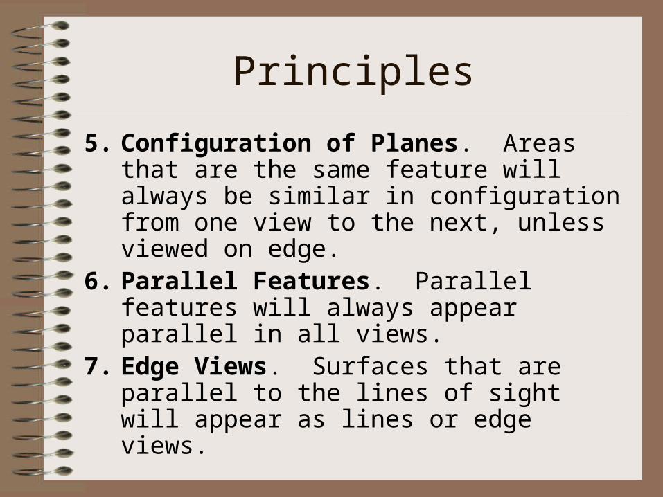
5. Configuration of Planes. Areas that are the same feature will always be similar in configuration from one view to the next, unless viewed on edge.
6. Parallel Features. Parallel features will always appear parallel in all views.
7. Edge Views. Surfaces that are parallel to the lines of sight will appear as lines or edge views.
Fillets, Rounds, and Runouts
• See text for details on how to represent fillets and rounds.
• Runouts are special method of representing filleted surfaces that are tangent to cylinders.– Drawn from point of tangency.– See text for details.
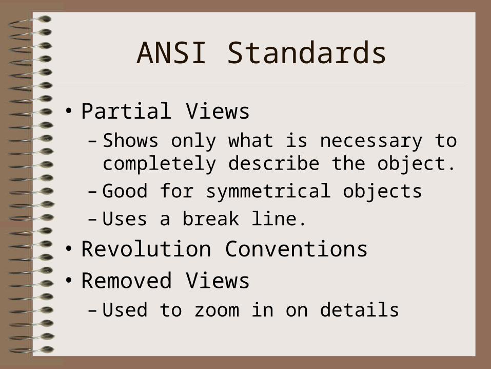
ANSI Standards
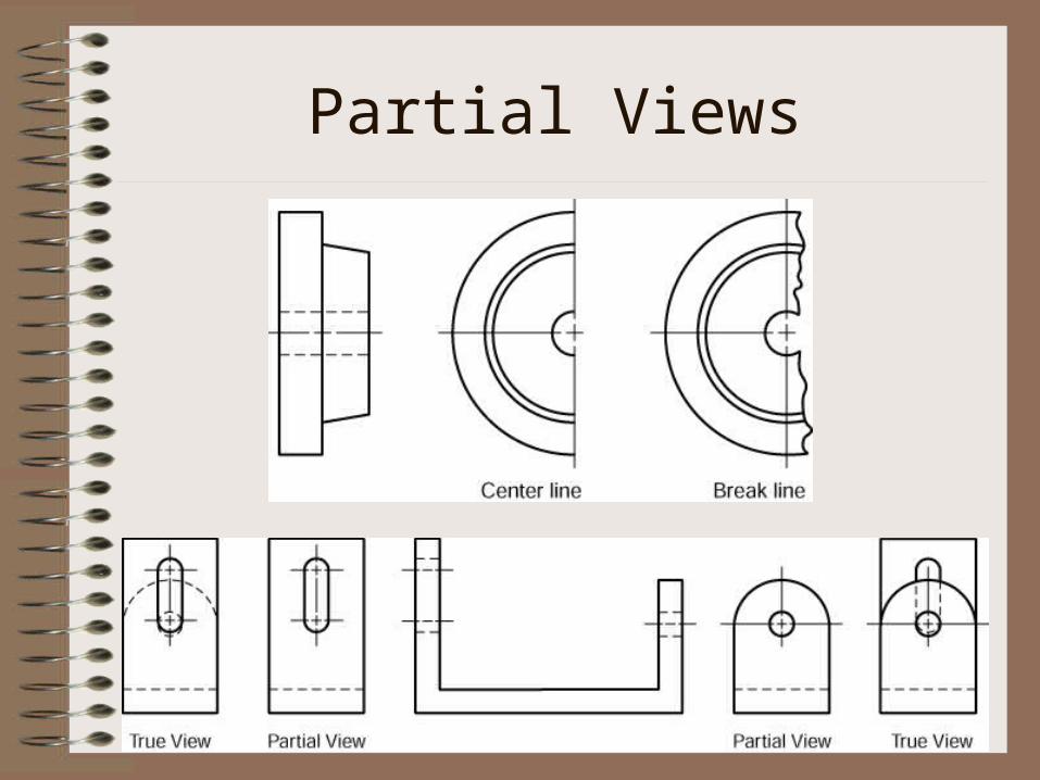
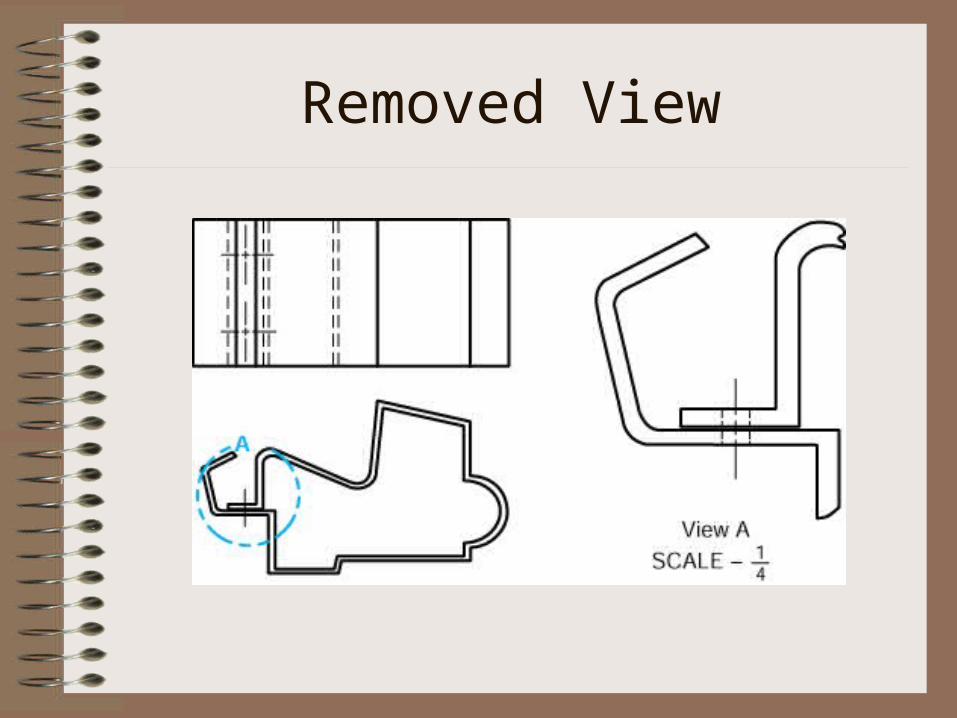
• Partial Views– Shows only what is necessary to completely
describe the object.– Good for symmetrical objects– Uses a break line.