LBL-3 6 645 UC-406 Multicusp Sources for Ion Beam Lithography Applications K.N. Leung, P. Hen, W.B. Kunkel, Y. Lee, L. Perkins, D. Pickard, M. Sarstedt, M. Weber, and M.D. Williams Accelerator and Fusion Research Division Lawrence Berkeley Laboratory University of California Berkeley, California 94720 May 1995 This work was supported in part by the Advanced Lithography Group under CRADA BG94-212(00) with Lawrence Berkeley Laboratory and the U.S. Department of Energy under Contract No. DE-AC03-76SF00098.
Transcript
LBL-3 6 645 UC-406
Multicusp Sources for Ion Beam Lithography Applications
K.N. Leung, P. Hen, W.B. Kunkel, Y. Lee, L. Perkins, D. Pickard, M. Sarstedt, M. Weber, and M.D. Williams
Accelerator and Fusion Research Division Lawrence Berkeley Laboratory
University of California Berkeley, California 94720
May 1995
This work was supported in part by the Advanced Lithography Group under CRADA BG94-212(00) with Lawrence Berkeley Laboratory and the U.S. Department of Energy under Contract No. DE-AC03-76SF00098.
.- -
DISCLAIMER
This report was prepared as an account of work sponsored by an agency of the United States Government. Neither the United States Government nor any agency thereof, nor any of their employees, make any warranty, express or implied, or assumes any legal liability or responsibility for the accuracy, completeness, or usefulness of any information, apparatus, product, or process disclosed, or represents that its use would not infringe privately owned rights. Reference herein to any specific commercial product, process, or service by trade name, trademark, manufacturer, or otherwise does not necessarily constitute or imply its endorsement, recommendation, or favoring by the United States Government or any agency thereof. The views and opinions of authors expressed herein do not necessarily state or reflect those of the United States Government or any agency thereof.
.
LBL-36645 UC-406
Mult icusp Sources for Ion B e a m Lithography Appl ica t ions*
K. N. Leung, P. Herz, W. 8. Kunkel, Y. Lee, L. Perkins, D. Plckard, M. Sarstedt, M. Weber, and M. D. Williams
Lawrence Berkeley Laboratory University of California
Berkeley, CA 94720 U S A
Abstract
Application of the multicusp source for Ion Projection Lithography is described. It is shown that the longitudinal energy spread of the positive ions at the extraction aperture can be reduced by employing a magnetic filter. The advantages of using volume-produced H- ions for ion beam lithography is also discussed.
* This work was supported by the Advanced Lithography Group under CRADA BG94-212(00) with Lawrence Berkeley Laboratory and the US. Department of Energy Contract No. DE-AC03-76SF00098.
INTRODUCTION
Ion Projection Lithography (IPL) aims at the possibilities of projecting sub-0.20 pm patterns of a stencil mask onto a wafer substrate. In order to keep the chromatic aberrations below 25 nm, an ion source which delivers a beam with an energy spread of less than 3 eV is required. For this application, permanent-magnet multicusp plasma
generators are being considered.’ These types of plasma sources are capable of producing large volumes of uniform, quiescent and high-density plasmas with high gas and electrical efficiencies. They are now being used in neutral beam injection systems for fusion reactors, particle accelerators, ion implantation systems, neutron tubes for oil-well logging and proton therapy machines. In this paper, schemes for reducing the longitudinal energy spread of the accelerated ions are described. It has been demonstrated that the use of a magnetic filter can improve both the concentration of atomic hydrogen ion species in the extracted beam and the longitudinal energy spread of the accelerated ions.
EXPERIMENTAL SETUP
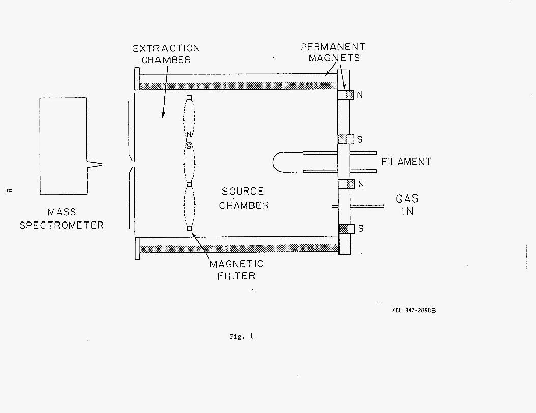
Figure 1 is a schematic diagram of a typical multicusp ion source. The external surface of the source chamber is surrounded by rows of permanent-magnets which generate longitudinal line-cusp magnetic fields that can confine the primary ionizing electrons very efficiently. One end of the chamber is terminated by an end flange which is covered with rows of permanent magnets to complete the line-cusp arrangement. The open end of the chamber is enclosed by a three-electrode extraction system. The first or plasma electrode is maintained either at the anode potential or at the floating potential. A steady-state helium plasma was produced by primary electrons emitted from a set of tungsten filaments, and the entire chamber wall served as the anode for the discharge.
Plasma density and potenital distributions were obtained with a moveable
2
.
Langmuir probe. The transverse ion temperature can be measured from the emittance of the accelerated beam. A two-grid retarding field energy analyzer was used to study the longitudinal energy spread of the positive ion species at the exit aperture of the ion source. The ion species and the current of the extracted beam were measured by a magnetic mass spectrometer and a Faraday cup respectively.
EXPERIMENTAL RESULTS
Figure 2 shows the radial plasma density profile for a 30-cm-diam source chamber surrounded by 12 columns of permanent magnets. The plasma potential has a similar radial distribution. Within the central uniform region, one can expect that the transverse ion temperature is dominated by the thermal temperature of the ion species. For a hydrogen discharge, the atomic hydrogen ion species has a transverse
temperature of about 1 eV while the molecular ions have a lower value.*
The axial or longitudinal plasma density and potential distributions have been
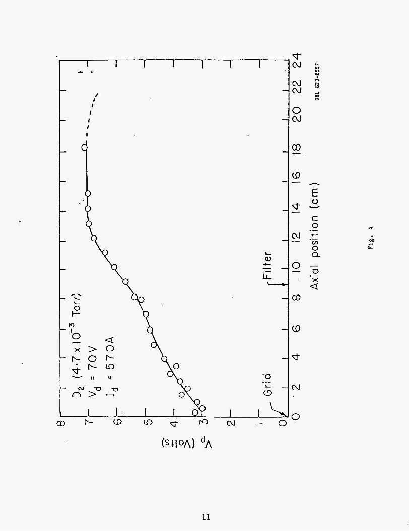
investigated in previous experiment^.^ Figures 3 and 4 show the axial plasma
potential (V,) distribution when the ion source is operated without and with a magnetic
filter4 The filter provides a limited region of transverse magnetic field, which is made
strong enough to prevent the energetic electrons in the “source” chamber from crossing over into the “extraction” chamber, but is weak enough for some plasma to diffuse into the extraction region.
Figure 3 is a plot of Vp as a function of the axial position when the source was operated .‘without the filter. The profile shows that Vp decreases monotonically towards the plasma electrode. Positive ions formed on the left side of the maximum can roll down and reach the extractor. Since the ions are generated at positions with different plasma potential, they will have a spread on the axial energy when they arrive at the extraction aperture. In the presence of a filter, the potential distribution is very uniform in the discharge chamber region (Fig. 4). Since the majority of the positive ions are generated in the source chamber region, they arrive at the plasma electrode
3
with about the same energy. One therefore expects that the longitudinal energy spread of the ions should be reduczd.
A .two-grid electrostatic energy analyzer was used to measured the longitudinal energy spread of the ions at the exit aperture: The experimental arrangement is shown in Fig. 5. The energy analyzer is positioned at the exit aperture. The first screen is biased at a very negative potential (- -90 V) to repell all the incoming electrons. A voltage ramp is applied on t h e second screen to discriminate ions with various energies. The last electrode collects all the incoming ions.
Figure 6 shows the results of the longitudinal energy spread measurement. The total energy variation (spread of the longitudinal energy) is found to be about 7.5 eV for the case without the filter and is reduced to approximately 4.5 eV when the filter is installed. The reduction in the longitudinal energy spread by employing the magnetic filter has also been observed in an external retarding energy analyzer after the beam
is accelerated to -5 keV5
The filter offers several advantages for the multicusp ion source operation. In addition to reducing the longitudinal energy spread of the positive ions, it can also enhance the atomic ion species in the extracted beam when diatomic gases such as
H2 and N2 are used for the di~charge.~ When t h e filter and discharge conditions are optimized, an atomic hydrcgen ion fraction higher than 90% has been achieved. For ion projection lithography applications, the axial position of the magnetic filter should be properly adjusted so that the B-field of the filter will not interfere with the ion extraction optics. Work is now in progress to measure the emittance, and therefore the transverse energy of the extracted ions when t h e multicusp source is operated with and without the filter. Results of these measurements will be reported in the near future.
DISCUSSION
Apart from the filter arrangement, one can also reduce the longitudinal energy
4
spread by operating the multicusp source for volume H' ion production. In a volume
production source, the H" ions are formed by the dissociative attachment process.6 In
order to enhance the H' yield by this process, a water-cooled permanent-magnet filter
is installed in the source chamber. The hydrogen molecules are excited to high vibrational levels H*(t') by the energetic primary electrons in the source chamber region. As they migrate into the extraction chamber region,' low energy (-1 eV)
electrons are attached to them and H' ions are formed according to the following
interaction:
e+H2(v'') -> H**- -> H-+H
The filter-equipped multicusp generator arrangement provides the ideal source
configuration for the formation and extraction of volume-produced H' ions. Since these
H' ions are mainly formed near the extraction aperture, they should have a much
smaller longitudinal energy spread than the positive ions. In addition, negative ions impinging on the target will not generate high charging potentials. The accompanying electrons in the extracted beam are easily removed by an E x B filter. We plan to
measure the longitudinal energy spread of the H- ions by using the IMS (Ion
Microfabrication Systems GmbH)-type energy analyzer. Results of the findings will be reported.
ACKNOWLEDGMENT
We.would like to thank S. Wilde and T. McVeigh for technical assistance. This work is supported by the Advanced Lithography Group and the US. Department of Energy under contract No. DE-AC03-76SF00098.
5
Figure CaDtions
Fig. 1 Schematic diagram of the multicusp ion source. Fig. 2 Radial plasma density profiles (for three different dischage currents) for a
Fig. 3 Axial plasma potential profile of the multicusp source with no filter installed. Fig. 4 Axial plasma potential profile of the multicusp source in the presence of a filter. Fig. 5 Experimental setup for the longitudinal ion energy spread measurement. Fig. 6 The energy analyzer output signal versus the applied ramp voltage when the
30-cm-diam multicusp generator.
source is operated with and without the magnetic filter.
6
References
1. A. Chalupka et al., Proc. of the 38th Intl. Symposium on Electron, Ion and Photon Beams, New Orleans, Louisiana, May (1 994).
2. William S. Cooper, Klaus Halbach, and Steven B. Magyary, Proc. of the Second Symposium on Ion Sources and Formation of Ion Beams, Berkeley, CA (Oct 1974).
3. K. W. Ehlers, K. N. Leung, P1 A. Pincosy, and M. C. Vella, Appl. Phys. Lett.41, 517 (1 982).
4. K. W. Ehlers and K. N. Leung, Rev. Sci. Instrum., 52, 1452 (1981). 5. M. Sarstedt et al., Proc. of t h e 1995 Particle Accelerator Conference, Dallas, Texas
(May 1995). 6. K. N. Leung and W. B. Kunkel, Phys. Rev. Lett.,s, 787, 1987.
7
EXTRACTION CHAMBER
PERMANENT MAGNETS
1 .
D S :.>>>
F
MAGNETIC
SOURCE CHAMBER
MASS SPECTROMETER
ILAMENT
G A S I N
F ILTER ,
XBL 847-28988
Fig. 1
,
Radial Plasma Density Profile for a 30-cm-diam Chamber
Fig. 2
9
- t - I I I I I
b
’ 0 c >” L!J
1
73
(3
.- 1
d- -
N -
3 -
c 0
cn 0 Q
.- c .-
- 0 x .-
d
m
10
11
Multicusps Ion Source
F i g . 5
._._._._ ,. ....
_._ . ........ ._.-._. . - . .. . .
- c . - ' " . ; - . . , _ _ - I . - . - - . - -.- - - - i . - - i - - . - . .