1 Abstract Conventional transport aircrafts are becoming more flexible in order to achieve lower fuel consumption. Most part of the additional flexibility comes from the increased wing aspect ratio. This line of studies is composed by sequential phases which come from Aerodynamics to Structures passing through Loads and Aeroelasticity technologies. This work proposes the integration of Aerodynamics and Structures through a multidisciplinary analysis, focusing on the high flexibility aspects of the wing in-flight shape for a recent, high aspect ratio aircraft. This work aims to understand the changes in the loads and structural sizing processes due to the increased flexibility of the wing. It uses a recent and high aspect ratio aircraft as a study case. Potential Computational Fluid Dynamics and nonlinear Finite Elements Method analyses are integrated employed in this study. Large displacements was included in the process, showing impacts for future development methodologies. 1 Introduction There are effects of the wing high aspect ratio in different technologies. These unknown effects became real when Helios prototype (ultra-high aspect ratio: 31) fell in the sea. In June 2003, it went through excessive oscillation, loss of control and then the structure failed. The flying wing structure high flexibility effects, underestimated in the development, were pointed as one of the reasons for the accident [10]. A glider classified as HALE (high altitude and long-endurance, aspect ratio: 17), in 2005, used nonlinear strain-based structural methods to consider high flexibility in the flight dynamics, showing differences in maneuvering responses [5]. Later on [6], reduced order structural geometric nonlinear effects were used to show differences in the expected trajectory of the flying wing X-HALE prototype (aspect ratio: 40). Looking to the future in commercial transport aviation, from October 2008 to March 2010, the Ultra Green Aircraft Research [4] described in more details the whole scenarios of technology developments expected for the next twenty years. The aspect ratios proposed to be investigated range from current 10 up to 16, when the configuration is conventional, and almost 27 for flying wings and strut-braced wing configurations. Aeroelastic tunnel test results and aeroelastic modeling procedures were presented in 2014 and 2015 for Green Aircraft Research [2] [3] considering a Truss-Braced wing configuration (aspect ratio: ~20). Tools for static aeroelastic solution considering reduced order nonlinear structure were used. Beam model structure with geometric nonlinearity and a combination of Doublet Lattice and Navier- MULTIDISCIPLINARY METHODS FOR WING FLIGHT SHAPE ANALYSIS - EFFECT OF THE GEOMETRIC NONLINEAR STRUCTURE FOR STATIC PULL-UP Angelo A. Verri 1 2 , Cesar Turcato Jorge 1 , Antônio F. Bizarro 1 , Flávio Luiz S. Bussamra 2 , Hermínio N. Silveira Júnior 1 , Carlos E. S. Cesnik 3 1 Brazilian Aeronautic Company - EMBRAER 2 Technological Institute of Aeronautics – ITA 3 University of Michigan - UniMich Keywords: Structural Analysis and Design, Structural Dynamics, Aeroelasticity
Transcript
1
Abstract Conventional transport aircrafts are becoming more flexible in order to achieve lower fuel consumption. Most part of the additional flexibility comes from the increased wing aspect ratio. This line of studies is composed by sequential phases which come from Aerodynamics to Structures passing through Loads and Aeroelasticity technologies. This work proposes the integration of Aerodynamics and Structures through a multidisciplinary analysis, focusing on the high flexibility aspects of the wing in-flight shape for a recent, high aspect ratio aircraft. This work aims to understand the changes in the loads and structural sizing processes due to the increased flexibility of the wing. It uses a recent and high aspect ratio aircraft as a study case. Potential Computational Fluid Dynamics and nonlinear Finite Elements Method analyses are integrated employed in this study. Large displacements was included in the process, showing impacts for future development methodologies.
1 Introduction
There are effects of the wing high aspect ratio in different technologies. These unknown effects became real when Helios prototype (ultra-high aspect ratio: 31) fell in the sea. In June 2003, it went through excessive oscillation, loss of control and then the structure failed. The
flying wing structure high flexibility effects, underestimated in the development, were pointed as one of the reasons for the accident [10].
A glider classified as HALE (high altitude and long-endurance, aspect ratio: 17), in 2005, used nonlinear strain-based structural methods to consider high flexibility in the flight dynamics, showing differences in maneuvering responses [5]. Later on [6], reduced order structural geometric nonlinear effects were used to show differences in the expected trajectory of the flying wing X-HALE prototype (aspect ratio: 40). Looking to the future in commercial transport aviation, from October 2008 to March 2010, the Ultra Green Aircraft Research [4] described in more details the whole scenarios of technology developments expected for the next twenty years. The aspect ratios proposed to be investigated range from current 10 up to 16, when the configuration is conventional, and almost 27 for flying wings and strut-braced wing configurations. Aeroelastic tunnel test results and aeroelastic modeling procedures were presented in 2014 and 2015 for Green Aircraft Research [2] [3] considering a Truss-Braced wing configuration (aspect ratio: ~20). Tools for static aeroelastic solution considering reduced order nonlinear structure were used. Beam model structure with geometric nonlinearity and a combination of Doublet Lattice and Navier-
MULTIDISCIPLINARY METHODS FOR WING FLIGHT SHAPE ANALYSIS - EFFECT OF THE GEOMETRIC NONLINEAR STRUCTURE FOR STATIC PULL-UP
Angelo A. Verri 1 2, Cesar Turcato Jorge 1, Antônio F. Bizarro 1, Flávio Luiz S. Bussamra 2,
Hermínio N. Silveira Júnior 1, Carlos E. S. Cesnik 3
1 Brazilian Aeronautic Company - EMBRAER 2 Technological Institute of Aeronautics – ITA
3 University of Michigan - UniMich
Keywords: Structural Analysis and Design, Structural Dynamics, Aeroelasticity
Angelo A. Verri, Cesar Turcato Jorge, Antônio F. Bizarro, Flávio Luiz S. Bussamra, Hermínio N. Silveira Júnior, Carlos E. S. Cesnik
2
Stokes aerodynamics with geometry deflection updating were used. The aeroelastic stability nonlinear analysis presented more accurate results than the linear one when compared to test results. Current commercial transport aircrafts are becoming more flexible in order to achieve lower fuel consumption. Most of the additional flexibility comes from the increased wing aspect ratio. This study aims to investigate impacts on the structural sizing process due to the increased flexibility of the wing. The goal is to evaluate the effects of high flexibility for a recent aircraft, with aspect ratio of 12, on the structural sizing process.
This line of studies is composed by sequential phases, from Aerodynamics to Structures passing through Loads and Aeroelasticity technologies, resulting in a multidisciplinary analysis (MDA). The goal of the work is to integrate the process, in addition to including large-displacements nonlinear effects. This article includes nonlinear effects of the wing structure, whose deformations affect, of course, the aerodynamic loads distribution. Nonlinear FEM (Finite Elements Method) static analyses may include:
• large displacements; • nonlinear boundary conditions and/or
loads (like gaps and follower forces); • material nonlinear effects (like
plasticity). Follower forces are considered in this study in order to update the load direction and magnitude while the structure is deforming. Large displacements effects are also considered [1]. The implementation of an integrated multi-disciplinary static aeroelasticity process for the wing in-flight shape problem considering large-displacement effects leads to improvements for:
• the determination of the wing optimal geometrical torsion (jig shape),
• wing loads calculation, • calculation of the aeroelastic static
effects on aerodynamic coefficients,
• optimization of wing airfoils.
2 Aircraft
Similar model of recent conventional transport aircraft was used as a study case for this investigation, see Fig. 1(a). The aircraft model has wing aspect ratio of 12 and dimensions of a regional transport aircraft.
3 Aerodynamics
Wing-Body geometry was used for the computational fluid dynamics analysis. Viscous potential flow solver was employed in a steady-state simulation for a given flight condition, see Fig. 1(a). The pressure distribution result is the main output of the analysis and, for instance, the drag variation may be followed-up. The pressure distribution is post-processed to transform it into follower structural loads, which take into account the wing deformed shape.
4 Structures A half-wing FEM model clamped at the
root was used, see Fig. 1(b). The FEM model uses plates (for skin, spars and ribs) and bars (for stringers) to represent the structure in details. The inertial loads were not considered for this study in order to quantify only the aerodynamic effect. The solver used was Nastran® [7] [8] in both static linear analysis and static geometric nonlinear analysis. The deflections and rotations (three deflection and three rotations) along span are post-processed to transform them into wing geometric deformations.
Large displacements consideration is detailed by Bauchau and Hong [1]. Finite elements method considerations are available in MSC user manual [8] [9].
5 Integration The integrated process manages the
aerodynamic and structural processes in a closed-loop series of analyses. Fig. 2 shows the integrated process map illustration.
3
MULTIDISCIPLINARY METHODS FOR WING FLIGHT SHAPE ANALYSIS - EFFECT OF THE GEOMETRIC NONLINEAR STRUCTURE FOR STATIC PULL-UP
The initial pressure distribution for an undeformed wing (jig shape), at a given flight condition (altitude, Mach, weight and load factor), is the starting point for the analyses. This initial pressure distribution coming from an aerodynamic analysis is transformed into structural loads. The loads are applied to the structure, resulting in a deflected wing geometry. The same structural deflection is imposed to the wing-body geometry of the aerodynamic solver.
The integrated loop iterates along this process of deforming the wing and evaluating the corresponding aerodynamic loads on the deformed wing structure. It loops until convergence, when stable flight shape and flight static loads conditions are obtained. As a starting point, 10 iterations are analyzed for this phase. In Fig. 2, green boxes are processes and post-processes and red texts are output information transiting from one green box to the other.
6 Results
A pull-up maneuver was evaluated with linear and nonlinear structural analyses. Mach 0.78 was combined with aircraft maximum landing weight. Nine minutes is the total cluster CPU time needed for one iteration, which is mostly composed of the structural analysis. The process time for all other parts of the MDA takes only seconds. MDA process convergence occurs after four iterations for linear and nonlinear structures.
In the pull-up maneuver of 1.5g load factor, the magnitudes are sufficient to be considered important. Fig. 3(a) and 3(b) show, respectively, the vertical deflection and airfoil stream-wise torsion after convergence. The difference reaches 8.4% at the tip rotation when linear and nonlinear torsion results are compared. Significant differences in airfoil torsion occur from 60% to 100% of the semi-span.
Differences equal to or greater than 8% degrees on the tip of the wing are considered significant because this magnitude is comparable to the difference in flight shape for different aircraft design weights (for instance
Maximum Landing Weight to Maximum Take-off Weight). It also starts to become feasible to be measured during flight.
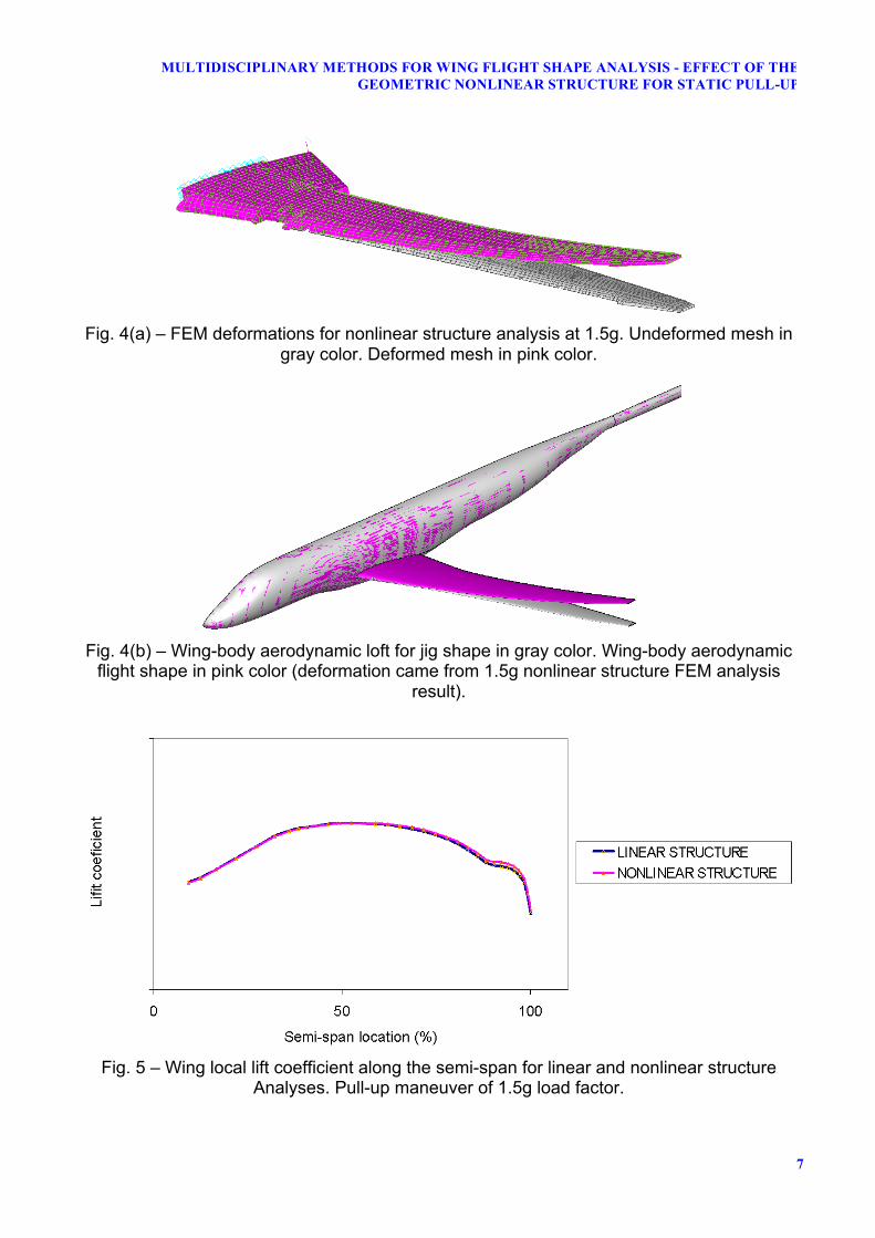
Fig. 4(a) shows the undeformed and deformed FEM model mesh for nonlinear structure at 1.5g. Fig. 4(b) shows the aerodynamic loft at jig shape and flight shape at 1.5g.
In terms of lift and loads distributions, Fig. 5 shows the local lift coefficient along the span for 1.5g load factor. The figure units and numbers are not in focus, but the difference between the linear structure analysis distribution along the semi-span compared to the nonlinear structure analysis distribution.
The total bending moment at wing root (at 9.2% of the semi-span) was in module 0.7% higher for nonlinear structure. Nonlinear structure shows a more loaded wing tip, as presented in Fig. 5, resulting in a higher bending moment at the root of the wing.
7 Conclusions The effect of geometric nonlinearity was
considered in the MDA, allowing for important comparison results against the current aircraft development methods. High flexibility effects have been quantified for an aspect ratio of ~12, based on viscous potential aerodynamics and nonlinear FEM analyses.
The pull-up 1.5g loads distribution for a geometric nonlinear structure analysis shifts outboard when compared to linear results, causing a small increase in bending moment (0.7%) at the wing root. This effect is not enough to impact the current dimensioning process of the wing, given the small magnitude of the change.
The presented MDA calculated the deformed flight shape for the investigated flight condition using a detailed structure and potential viscous flow aerodynamics. It permits future optimization both in structure and in aerodynamics considering the high flexibility effects.
Nine minutes cluster CPU time for one iteration is still a lot considering that millions of flight cases are evaluated in a typical loads loop.
Angelo A. Verri, Cesar Turcato Jorge, Antônio F. Bizarro, Flávio Luiz S. Bussamra, Hermínio N. Silveira Júnior, Carlos E. S. Cesnik
4
Potential viscous flow aerodynamics does not converge for high values of CL (lift coefficient), when nonlinear aerodynamic effects become significant, which is the case for flight conditions that are critical for wing loads.
In the future, if flexibility effects become even more significant, the methodology presented may be used to assess whether traditional methods remain adequate.
The stress analyses methods used must be consistent with the methodology employed in the loads analyses.
References
[1] Bauchau, O. A. and Hong, C. H. Nonlinear
composite beam theory. Journal of Applied Mechanics - Transactions of the ASME. Vol. 55, No. 1, 1988, pp. 156-163.
[2] Bartels, Robert E., Scott Robert C., Allen, Timothy J., Sexton, Bradley W.. Aeroelastic analysis of SUGAR truss-braced wing wind-tunnel model using FUN3D and a nonlinear structural model. 56th AIAA, 2015.
[3] Bartels, R. E., Scott, R. C., Funk, C. J., Allen, T. J., and Sexton, B. W.. Computed and experimental flutter/LCO onset for the Boeing truss-braced wing wind-tunnel model. 32st AIAA. 2014.
[4] Bradley, Marty K. and Droney, Christopher K. Subsonic Ultra Green Aircraft Research: Phase I Final Report. NASA. 2011.
[5] Cesnik, Carlos E. S., and Su, W.. Nonlinear aeroelastic modeling and analysis of fully flexible aircraft. 46th AIAA/ASME/ASCE/AHS/ASC Structures, Structural Dynamics and Materials Conference, AIAA 2005. 2005.
[6] Cesnik, Carlos E. S., Senatore, Patrick J., Su,Weihua, Atkins, Ella M., Shearer, Christopher M., Pitcher, Nathan A.. X-HALE: A very flexible UAV for nonlinear aeroelastic tests. 51st AIAA. 2010.
[7] MSC. Official website for MSC Nastran software version 2016R1. Available at: <http://www.msc software.com/product/msc-nastran>. Accessed on: 18/Jan/2017 at 7:00h.
[10] Noll, T. E., Brown, J. M., Perez-Davis, M. E., Ishmael, S. D., Tiffany, G. C., and Gaier, M.. Investigation of the Helios Prototype Aircraft Mishap. NASA Technical Report. 2004.
Copyright Statement The authors confirm that they, and/or their company or organization, hold copyright on all of the original material included in this paper. The authors also confirm that they have obtained permission, from the copyright holder of any third party material included in this paper, to publish it as part of their paper. The authors confirm that they give permission, or have obtained permission from the copyright holder of this paper, for the publication and distribution of this paper as part of the ICAS proceedings or as individual off-prints from the proceedings.
5
MULTIDISCIPLINARY METHODS FOR WING FLIGHT SHAPE ANALYSIS - EFFECT OF THE GEOMETRIC NONLINEAR STRUCTURE FOR STATIC PULL-UP
Figures
(a) (b)
Fig. 1 - Models.
a) Wing-Body geometry for fluid dynamics simulation. b) Wing clamped at the root.
Fig. 2 – Integrated process map illustration
Angelo A. Verri, Cesar Turcato Jorge, Antônio F. Bizarro, Flávio Luiz S. Bussamra, Hermínio N. Silveira Júnior, Carlos E. S. Cesnik
6
Fig. 3(a) – Wing vertical deflection along the semi-span for linear and nonlinear structure analyses. Pull-up maneuver of 1.5g load factor.
Fig. 3(b) – Wing local incidence change along the semi-span for linear and nonlinear structure analyses. Pull-up maneuver of 1.5g load factor.
7
MULTIDISCIPLINARY METHODS FOR WING FLIGHT SHAPE ANALYSIS - EFFECT OF THE GEOMETRIC NONLINEAR STRUCTURE FOR STATIC PULL-UP
Fig. 4(a) – FEM deformations for nonlinear structure analysis at 1.5g. Undeformed mesh in
gray color. Deformed mesh in pink color.
Fig. 4(b) – Wing-body aerodynamic loft for jig shape in gray color. Wing-body aerodynamic
flight shape in pink color (deformation came from 1.5g nonlinear structure FEM analysis result).
Fig. 5 – Wing local lift coefficient along the semi-span for linear and nonlinear structure