38
Marcos Esterman, Associate Professor Industrial and Systems Engineering Department Rochester Institute of Technology [email protected] Multidisciplinary Senior Design I System Design

Marcos Esterman, Associate ProfessorIndustrial and Systems Engineering DepartmentRochester Institute of [email protected]
Multidisciplinary Senior Design I
System Design

Agenda
Tuesday End-State Deliverables Functional Analysis
Example Team Project Work
Concept Generation Morphological Analysis
Thursday Concept Generation
Develop Alternatives Engineering Analysis Concept Selection

END-STATE DELIVERABLES – WEEK 6

Functional DecompositionVentilate
UnresponsivePerson (UP)
Access UP’s Airway Circulate Air
Intake Air Transport Air Control Air
Control Air Pressure
Sense Pressure
Change Pressure
Control Air Volume
Sense Air Volume
Change Air Volume
Control Breathing Rate
Sense Breathing rate
Change Breathing rate
Purify Air
Monitor Physiological Data
Sense Physiological Data
Transmit Physiological Data

Alternatives ConsideredCriteria
Have a modern look and feel - + + + + + +
Is Light weight + S - + - + -Is Small - + + S + - +
Is Easy to Use S + + + - S SHas Long-Lasting Portable Power S - - + S + -
Low Cost Functional Prototype S + S + - + -
Low UMC for Final Design + - + - S + SAlert user of the
following data: XXX - - + + + + +Measure Oxygen Levels - + S + + + -
Measure CO2 Levels + - + S + S +Transfer Data Wirelessly S - - S S - +Assist Human to Breathe + - S + S S S
Integrates into CPR Process + - + + + - -
Does not interfere with the following life-saving
measures: XXX+ S + + - S S
Improves air quality delivered to patient S - - S S - +
Is safe - + S S - + SIs reliable S - + + - + -
Needs to use principles in patents #5,211,170 and
# 5,398,676 S - S S + + S
Needs to be consistent with FDA 510K Approval + + - S + S -
+ 7 7 9 11 8 10 6- 5 10 5 1 6 4 7
DATU
M

Selected Concept Updates: Electronic controls
(decrease size/more options)
Smaller pump Reliable and smaller
battery Additions:
Ability to monitor and record vitals
Pulse oximeter feedback Voice alerts/instructions Carbon dioxide sensor

Architecture

Risk Assessment
Risk Item Effect Cause
Likelihood
Severity
Importance Action to Minimize Risk Owner
Date of Completion
1over heating
damaged components; total system failure
electronic components; environment; mis-use; upkeep
2 3 6 basic thermal analysis; provide safety cautions Dan week 9- MSD1
2Integration of hardware and software together
non-workable prototype
using devices from different companies that don't function together
2 2 4
plan and read specs on all technical components; test components compatability Derek week 9- MSD1
3inputs do not match outputs
failing to meet FDA requirements
programing and calibration errors
2 1 2quality testing of design
Chris/ Kennedy MSD2
4battery integration in system
underperforming; fire hazard
battery failure; not meeting engineering specs
1 2 2check with experts on how to manage battery functionality Eric MSD2
5 Durability failure
components breaking; failure of system
components malfunctioning during usage
2 3 6perform vibration testing; perform environmental testing Ryan MSD2
Tech Concerns
There is no shame in this being a large list, especially at this stage.Demonstrates that you are being realistic.

Test Plan (First Cut)
Test Pump Test Verify Mass Flow Rate
Test Mass Flow Sensor Verify Readings Match Pump Test Results
Test Pressure Sensor Compare against Flow Characteristics chart of the
Pressure sensor. Test User Interface
Verify ease of use

SYSTEM DESIGN

Considerations
Physical Decomposition Subsystem Identification
Functional Decomposition Specification Decomposition
Need to flow-down specifications

FUNCTIONAL ANALYSIS

What is a function?
Function – active verb, noun A clear, reproducible relationship between the available
input and the desired out of the product, independent of any particular form
Examples: Make Copies, Chop Beans, Clip Nails
Otto, K., Wood, Kristin L., Product Design: Techniques in Reverse Engineering and New Product Development, Prentice Hall, Upper Saddle, NJ 2001, pp. 152 – 151. 13
Product Represented as a Functional System
Energy
Material
Information
Energy
Material
Information

Example

What is the function of this?
Product Represented as a Functional System
Energy
Material
Information
Energy
Material
Information
Open CanCan
Sealed Can
Can, Lid, Contents
Opened Can
Energy could be manual, electric, kinetic, potential, etc. depending on solution, so typically only worry about flows that will not change
What is the function? What flows will not change?
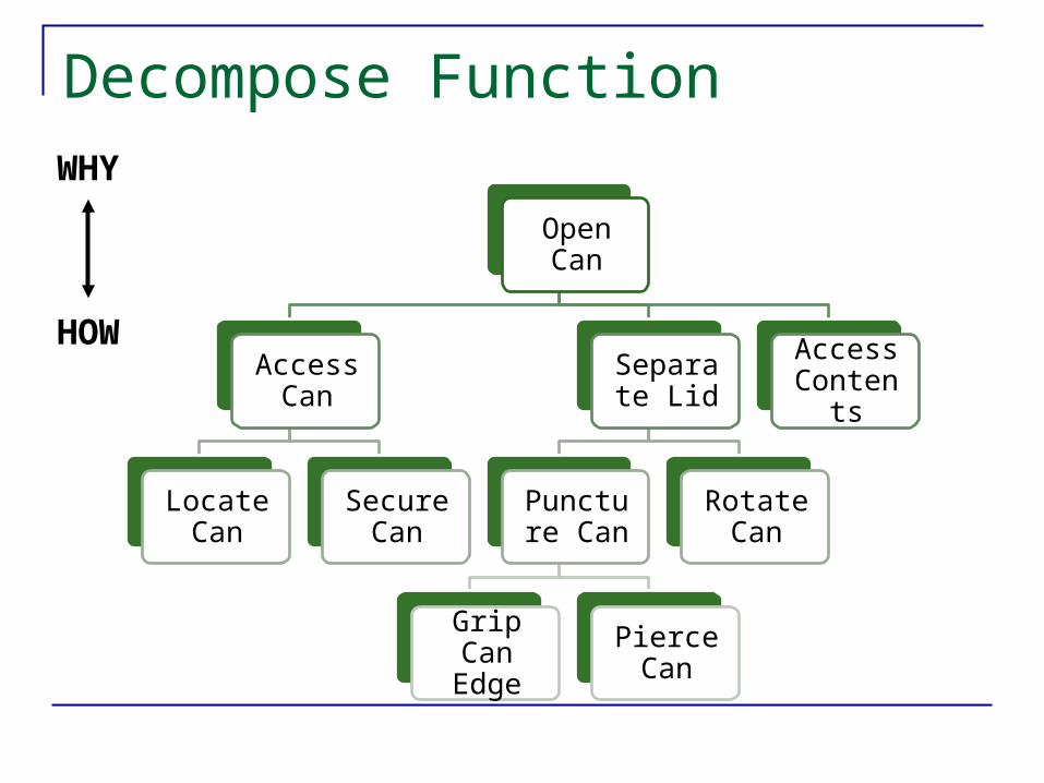
Decompose Function
Open Can
Access Can
Locate Can
Secure Can
Separate Lid
Puncture Can
Grip Can Edge
Pierce Can
Rotate Can
Access Contents
HOW
WHY
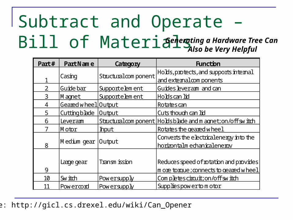
Subtract and Operate – Bill of Materials
Part # Part Name Category Function
1Casing Structural component
Holds, protects, and supports internal and external components
2 Guide bar Support element Guides lever arm and can3 Magnet Support element Holds can lid4 Geared wheel Output Rotates can5 Cutting blade Output Cuts though can lid6 Lever arm Structural component Holds blade and magnet; on/off switch7 Motor Input Rotates the geared wheel
8Medium gear Output
Converts the electrical energy into the horizontal mechanical energy
9Large gear Transmission Reduces speed of rotation and provides
more torque; connects to geared wheel10 Switch Power supply Completes circuit; on/off switch11 Power cord Power supply Supplies power to motor
Source: http://gicl.cs.drexel.edu/wiki/Can_Opener
Generating a Hardware Tree Can Also be Very Helpful

Subtract & Operate
Part # Part Name
1Casing
2 Guide bar3 Magnet4 Geared wheel5 Cutting blade6 Lever arm7 Motor
8Medium gear
9Large gear
10 Switch11 Power cord
Open Can
Access Can
Locate Can
Secure Can
Separate Lid
Puncture Can
Grip Can Edge
Pierce Can
Rotate Can
Access Contents
Protect Opener
Capture Lid
Added Functions
ActuateOpener

Subtract & Operate Method
Bottom-up approach Assumes product or product concept exists
Steps Remove one component of the assembly
Literally or Figuratively “Operate” system through its full range Analyze effect Deduce the sub-function of the missing component Repeat for all components Modify function tree
Otto, K., Wood, Kristin L., Product Design: Techniques in Reverse Engineering and New Product Development, Prentice Hall, Upper Saddle, NJ 2001, Chapter 5. 19

Modified Functional Decomposition
Open Can
Access Can
Locate Can Secure Can
Actuate Opener Separate Lid
Puncture Can
Grip Can Edge Pierce Can
Rotate Can
Transmit Electrical Energy
Covert Electrical Energy to Rotation
Covert Rotation to Torque
Capture Lid Access Contents Protect Opener

Process Flow Can Also be Helpful
Access Can
Secure Can
Actuate Opener
Separate Lid
Capture Lid
Access Contents
Grasp Can
Attach Opener
Apply Lever
PierceCan
RotateHandle
Transmit Torque
Capture Lid
Access Content
High-Level View
Low-Level View

FUNCTIONAL ANALYSIS WORKSHOP

Exercise - Define your project’s top level function (5 minutes) Remember that the top level function should
manipulate material, energy and/or information that is external to your system
23

Functional Decomposition Exercise – (20 minutes) Generate the 1st level (& 2nd Level, if possible)
of Decomposition for your top level-function Ensure that it is as solution independent as
possible
24
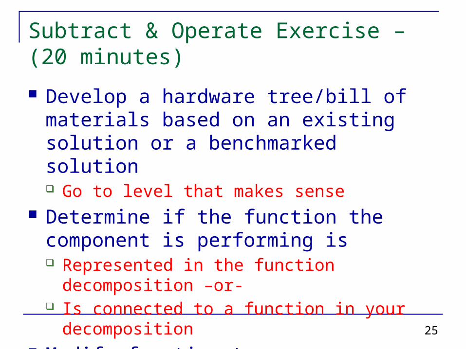
Subtract & Operate Exercise – (20 minutes) Develop a hardware tree/bill of materials
based on an existing solution or a benchmarked solution Go to level that makes sense
Determine if the function the component is performing is Represented in the function decomposition –or- Is connected to a function in your decomposition
Modify function tree
25

CONCEPT GENERATION
26

27
5-Step Process (Ulrich & Eppinger, pg. 100)
Clarify the Problem Start from Product Definition Decomposition Prioritize
Search Externally Lead users Experts Patents Benchmarking
Search Internally dfX Analysis Field Feedback Institutional Knowledge Supply Chain
Explore Systematically Classification Tree Combination Tree Morphological Analysis TRIZ
Reflect on Process & Solutions
1. Clarify the Problem
5. Reflect onSolutions
4. ExploreSystematically
3. SearchInternally
2. SearchExternally
Sub-problems
ExistingConcepts
NewConcepts
IntegratedSolutions

Secrets of Concept Generation Employ many techniques Focus on values / functions Avoid premature closure Generate several alternatives
“Sky High” “Challenging technology” “Low Risk”
Screen ideas systematically e.g., Pugh selection process
Ishii, 200428

Morphology Study of shape
and form Morph. Analysis
Systematic study to analyze the possible shape and form
Morphological Diagram Example: Potato
Harvesting Machine
Pahl and BeitzMorphological Analysis
29

Bathroom Scale Example Expand Functions to manageable sub-functions
MeasureWeight
SupportSubject
Conv.Mass to Signal
IndicateSignal
HoldPartsTogether
Start with Functional Diagram
Ishii, 200430

Bathroom Scale
MeasureWeight
SupportSubject
Conv.Mass to Signal
IndicateSignal
HoldPartsTogether
Spring StrainGauge
CountMolecules
CornFlakes
Dial Voice Sound DigitalDisplay
Plate Box Bubble
Screws Glue
Use the Function Diagram to Generate Concepts
Ishii, 200431

Feasible (Conventional) Bathroom Scale
MeasureWeight
SupportSubject
Conv.Mass to Signal
IndicateSignal
HoldPartsTogether
Spring StrainGauge
CountMolecules
CornFlakes
Dial Voice Sound DigitalDisplay
Plate Box Bubble
Screws Glue
Generate Feasible Solutions
Ishii, 200432

“Sharper Image” Bathroom Scale
MeasureWeight
SupportSubject
Conv.Mass to Signal
IndicateSignal
HoldPartsTogether
Screws
Spring StrainGauge
CountMolecules
CornFlakes
Dial Voice Sound DigitalDisplay
Plate Box Bubble
Glue
Generate “Sky high” Ideas too...
Ishii, 200433

MorphChart
34
Douglas Axtell, Don Moran,Jason Stanbro, Jim Vermeire, 0303-786 & 0303-788 Class Project, 2010

Can Opener Example

Can Opener ExampleAccess Can
Actuate Opener
Puncture Can
Rotate Can
Capture Lid
Access Contents
Protect Opener
grasp

Concept Generation Exercise – Morphological Table(30 minutes)
Start generating your morphological table and finish for homework
37

Desired Output
Function Tree 2-3 Layers of Decomposition
Subsystem Identification Should be based both on existing artifact and
functional analysis Specification Flow-down
If you identify functional modules and/or subsystems, need to understand how you will assess them
Conceptually no different than what you did at the system-level
This will set you up for developing good solution alternatives


