MULTIFUNCTIONAL HYBRID CARBON NANOTUBE/CARBON FIBER POLYMER COMPOSITES Jin Ho Kang 1 , Roberto J. Cano 2 , James G. Ratcliffe 2 , Hoa Luong 2 , Brian W. Grimsley 2 , and Emilie J. Siochi 2 1 National Institute of Aerospace, Hampton, VA 23666 2 NASA Langley Research Center, Hampton, VA 23681 ABSTRACT For aircraft primary structures, carbon fiber reinforced polymer (CFRP) composites possess many advantages over conventional aluminum alloys due to their light weight, higher strength- and stiffness-to-weight ratio, and low life-cycle maintenance costs. However, the relatively low electrical and thermal conductivities of CFRP composites fail to provide structural safety in certain operational conditions such as lightning strikes. Despite several attempts to solve these issues with the addition of carbon nanotubes (CNT) into polymer matrices, and/or by interleaving CNT sheets between conventional carbon fiber (CF) composite layers, there are still interfacial problems that exist between CNTs (or CF) and the resin. In this study, hybrid CNT/CF polymer composites were fabricated by interleaving layers of CNT sheets with Hexcel ® IM7/8852 prepreg. Resin concentrations from 1 wt% to 50 wt% were used to infuse the CNT sheets prior to composite fabrication. The interlaminar properties of the resulting hybrid composites were characterized by mode I and II fracture toughness testing (double cantilever beam and end-notched flexure test). Fractographical analysis was performed to study the effect of resin concentration. In addition, multi-directional physical properties like thermal conductivity of the orthotropic hybrid polymer composite were evaluated. Interleaving CNT sheets significantly improved the in-plane (axial and perpendicular direction of CF alignment) thermal conductivity of the hybrid composite laminates by 50 – 400%. 1. INTRODUCTION Over the past decade, aircraft redesigns have moved from metals to the use of carbon fiber reinforced polymer (CFRP) composites, because they provide light weight, increased fuel efficiency, reduced pollutant emission, higher strength- and stiffness-to-weight ratio, and lower life-cycle maintenance due to their superior fatigue and corrosion resistance [1-2]. The Boeing 787 dreamliner and the Airbus A350 XWB feature approximately 50% CFRP by structural weight [1-2]. However, CFRP airframes suffer from several problems in connection with lightning strike damage. Commercial airplanes experience one lightning strike for every 1,000 to 10,000 hours of flight or one or two strikes a year, leading to cosmetic or structural damage [2-3]. A typical lightning strike delivers an impact force of 16 kN, an electrical current of 10 - 200 kA, and a thermal flux of up to 28,000C [3-4]. Compared to traditional aluminum structures, CFRPs possess lower electrical and thermal conductivities and are unable to dissipate the electrical current and thermal energy as effectively. The result can be embrittlement, delamination and/or structural failure [2]. https://ntrs.nasa.gov/search.jsp?R=20160009129 2018-05-19T07:02:22+00:00Z
Jin Ho Kang1, Roberto J. Cano2, James G. Ratcliffe2, Hoa Luong2, Brian W. Grimsley2, and Emilie J. Siochi2
1National Institute of Aerospace, Hampton, VA 23666 2NASA Langley Research Center, Hampton, VA 23681
ABSTRACT
For aircraft primary structures, carbon fiber reinforced polymer (CFRP) composites possess many advantages over conventional aluminum alloys due to their light weight, higher strength- and stiffness-to-weight ratio, and low life-cycle maintenance costs. However, the relatively low electrical and thermal conductivities of CFRP composites fail to provide structural safety in certain operational conditions such as lightning strikes. Despite several attempts to solve these issues with the addition of carbon nanotubes (CNT) into polymer matrices, and/or by interleaving CNT sheets between conventional carbon fiber (CF) composite layers, there are still interfacial problems that exist between CNTs (or CF) and the resin. In this study, hybrid CNT/CF polymer composites were fabricated by interleaving layers of CNT sheets with Hexcel® IM7/8852 prepreg. Resin concentrations from 1 wt% to 50 wt% were used to infuse the CNT sheets prior to composite fabrication. The interlaminar properties of the resulting hybrid composites were characterized by mode I and II fracture toughness testing (double cantilever beam and end-notched flexure test). Fractographical analysis was performed to study the effect of resin concentration. In addition, multi-directional physical properties like thermal conductivity of the orthotropic hybrid polymer composite were evaluated. Interleaving CNT sheets significantly improved the in-plane (axial and perpendicular direction of CF alignment) thermal conductivity of the hybrid composite laminates by 50 – 400%.
1. INTRODUCTION
Over the past decade, aircraft redesigns have moved from metals to the use of carbon fiber reinforced polymer (CFRP) composites, because they provide light weight, increased fuel efficiency, reduced pollutant emission, higher strength- and stiffness-to-weight ratio, and lower life-cycle maintenance due to their superior fatigue and corrosion resistance [1-2]. The Boeing 787 dreamliner and the Airbus A350 XWB feature approximately 50% CFRP by structural weight [1-2]. However, CFRP airframes suffer from several problems in connection with lightning strike damage.
Commercial airplanes experience one lightning strike for every 1,000 to 10,000 hours of flight or one or two strikes a year, leading to cosmetic or structural damage [2-3]. A typical lightning strike delivers an impact force of 16 kN, an electrical current of 10 - 200 kA, and a thermal flux of up to 28,000C [3-4]. Compared to traditional aluminum structures, CFRPs possess lower electrical and thermal conductivities and are unable to dissipate the electrical current and thermal energy as effectively. The result can be embrittlement, delamination and/or structural failure [2].
For lightning strike protection (LSP), major aerospace companies utilize metallic woven mesh embedded beneath the paint scheme as a sacrificial layer which can dissipate the electrical and thermal energy by ablation during a lighting strike [3,5]. This provides excellent protection, but it can negate the cost and weight saving benefits from the use of CFRP composites [3].
An alternative method of LSP for CFRP is by incorporating carbon nanotubes (CNTs) to improve the electrical and thermal conductivity without degrading mechanical strength [1,3,6]. Charkravarthi et al. demonstrated that the addition of 4% nickel coated CNT to CF reinforced bismaleimide composite increased the electrical conductivity by 10 orders of magnitude and significantly enhanced the LSP [6]. Grimsley et al. reported that interleaving stretched CNT sheets between carbon fiber prepreg layers increased the electrical conductivity by over one order of magnitude and also significantly enhanced the interlaminar shear fracture toughness [1]. Nguyen et al. also reported increased interlaminar fracture toughness with interleaved aligned CNT sheets [7-8].
However, there are still interfacial problems that exist between CNTs (or CF) and the resin due to the manufacturing process not being fully optimized. In addition, it is important to understand the orthotropic properties along the three orthogonal directions of unidirectional hybrid CNT/CF composite (axial, perpendicular to axial/in-plane, and perpendicular to axial/out-of-plane). In this paper, mode I and II fracture toughness were measured in order to evaluate the effects of CNT and resin concentration on the interfacial strengths of hybrid CNT/CF polymer composites. In addition, the directional thermal conductivities were evaluated.
2. EXPERIMENTAL
2.1 Materials
Hexcel IM7/8552 prepreg (12,000 filaments per tow (12k), fiber areal weight (FAW) of 145 g/m2 with 35% resin content) was used for preparing hybrid CNT/CF polymer composites. The cured ply thickness was reported to be 0.131 mm [1,9]. CNT sheet was purchased from Nanocomp Technologies, Inc., Merrimack, NH (Lot# 71019, single walled- (SW-) and few walled-CNT (FWCNT), acetone condensed). Average areal density of the CNT sheet was 9.8 g/m2. The CNT sheets possess an inherent directionality due to the drawing process, and this machine direction (MD) was termed the 0 direction [1]. A commercial toughened epoxy resin which has similar properties to Hexcel 8552 was used to pre-impregnate the CNT sheets (API-60, Applied Poleramic, Inc., Benicia, CA). Methyl ethyl ketone (MEK) and cyclohexanone (Sigma-Aldrich, St. Louis, MO) were used as received to make dilute API-60 resin solutions.
2.2 Hybrid CNT/CF Composite Fabrication
Hybrid CNT/CF polymer composites were fabricated by following the National Aeronautics and Space Administration Langley Research Center (NASA LaRC) developed procedure [1,10]. Various concentrations of toughened epoxy resin solution were prepared by dissolving API-60 epoxy resin either in MEK to make up a 50wt% solution or in a mixture of MEK and
cyclohexanone (1:3 ratio) to make up 1 and 5wt% solutions. The predetermined amount of API-60 solution was painted on the CNT sheets to fabricate “pre-infused” CNT/epoxy prepreg sheet with desirable weight fractions of CNT after vacuum drying at room temperature overnight (60, 75 and 95wt%). To prepare stretched CNT sheets, the CNT sheet was stretched to approximately 120% of its original length using a mechanical extension apparatus. The detailed processing method is described elsewhere [10]. The pre-infused CNT/epoxy prepreg sheets were used for further fabrication of hybrid CNT/CF composites. For double cantilever beam (DCB) and end notch flexure (ENF) coupons, panels (30.5 30.5cm) with 32 plies of IM7/8552 prepreg were fabricated by interleaving aligned, pre-infused CNT/epoxy prepreg sheets (7.6 7.6cm) between the 16th and 17th plies of IM7/8552 prepreg adjacent to the 12.5m thick Teflon® film used as a crack-starter.
For thermal conductivity test coupons, 80 plies of IM7/8552 prepreg (7.6 7.6cm) were interleaved with 80 plies of pre-infused CNT prepreg sheet. The 0 direction of the CNT sheet aligned with the 0 direction of the carbon fibers. The hybrid stack of plies was placed in a stainless steel mold and cured in a vacuum hot press according to a recommended Hexcel cure process. After cure, the panels were cut along the three orthogonal directions by a wet-saw and polished. The fabricated sample panels are listed in Table 1.
Table 1. Sample panels for characterization.
Property characteri-zation
Panel size (cm)
Sample Name
CNT content in pre-infused CNT sheet (wt%)
Epoxy solution concentra-tion (wt%)
Degree of stretching of CNT sheet (%)
Number of IM7/ 8552 plies
Ply Lay-up Configura-tion
Mode I Fracture Toughness
30.5 30.5
DCB-Control
N/A N/A N/A 32 [0]32
DCB-60-50-NS
60 50 None 32 [016/CNT/016]
DCB-60-5-NS
60 5 None 32 [016/CNT/016]
DCB-75-5-NS
75 5 None 32 [016/CNT/016]
DCB-95-1-NS
95 1 None 32 [016/CNT/016]
DCB-60-5-S
60 5 20 32 [016/CNT/016]
Mode II Fracture Toughness
30.5 30.5
ENF-Control
N/A N/A N/A 32 [0]32
ENF-60-50-NS
60 50 None 32 [016/CNT/016]
ENF-60-5-NS
60 5 None 32 [016/CNT/016]
ENF-75-5-NS
75 5 None 32 [016/CNT/016]
ENF-95-1-NS
95 1 None 32 [016/CNT/016]
ENF-60-5-S
60 5 20 32 [016/CNT/016]
Thermal Conducti-vity
7.5 7.5
TC-Control N/A N/A N/A 80 [0]80
TC-CNT 60 5 None 80 [0/CNT]80
2.3 Fracture Toughness Characterization
2.3.1 Mode I Interlaminar Fracture Toughness Test
Mode I Double Cantilever Beam (DCB) test coupons were fabricated and tested at room temperature of approximately 23C according to ASTM Standard D5528-13 [1,11]. An MTS-858 table-top servo-hydraulic test frame with a 2250 N load cell was used. Displacement was controlled at a rate of 1.27 mm/min until the crack propagated 40 mm. Since it yields more conservative values compared to the other methods such as compliance methods (CC), or a modified compliance calibration method (MCC), Mode I fracture toughness, GIC, was calculated using the Modified Beam Theory (MBT):
)(2
3
ab
PGIC
[1]
where a is the crack extension or delamination length, P is applied maximum load, δ is the load-point displacement, b is a specimen width and Δ is the delamination length correction factor determined by a least squares linear fit of the observed delamination length, a, versus the cube root of the corresponding compliance [1,11-12].
2.3.2 Mode II Interlaminar Shear Fracture Toughness Test
Mode II interlaminar shear fracture toughnesses of the composites were characterized at room temperature of approximately 23C using the End Notch Flexure (ENF) test method described elsewhere [1,13]. Mode II fracture toughness, GIIC, was calculated using following equation:
GIIC 3mPmax
2 a02
2B
[2]
where m is the compliance calibration (CC) coefficient, P is the applied load, a0 is the crack delamination length, and B is the sample width.
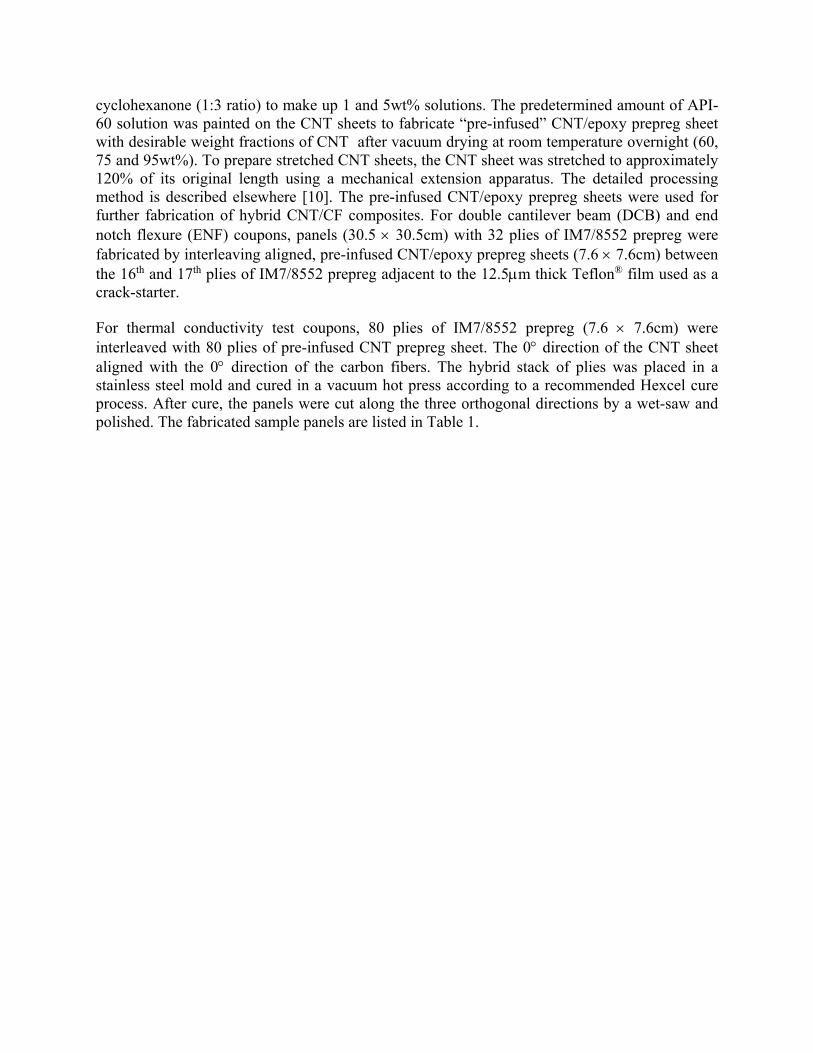
Thick (approximately 13 ~ 16 mm) composite plates – 80-ply control CF composites ([0]80) and 160-ply hybrid CNT/CF polymer composites ([0/CNT]80) were cut along the three orthogonal directions as shown in Figure 1. Hybrid CNT/unidirectional CF epoxy polymer composites have orthotropic thermal conductivity properties. The axial (1-), perpendicular/in-plane direction (2-), and perpendicular/out-of-plane (3-) direction to CF alignment formed the orthogonal principal directions for the unidirectional hybrid composites.
Figure 1. Preparation of orthotropic thermal conductivity test specimens.
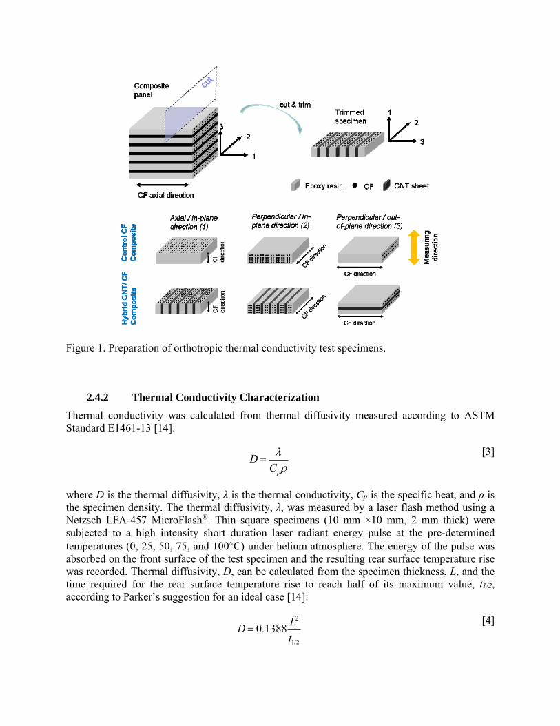
2.4.2 Thermal Conductivity Characterization
Thermal conductivity was calculated from thermal diffusivity measured according to ASTM Standard E1461-13 [14]:
D Cp
[3]
where D is the thermal diffusivity, λ is the thermal conductivity, Cp is the specific heat, and ρ is the specimen density. The thermal diffusivity, λ, was measured by a laser flash method using a Netzsch LFA-457 MicroFlash®. Thin square specimens (10 mm ×10 mm, 2 mm thick) were subjected to a high intensity short duration laser radiant energy pulse at the pre-determined temperatures (0, 25, 50, 75, and 100C) under helium atmosphere. The energy of the pulse was absorbed on the front surface of the test specimen and the resulting rear surface temperature rise was recorded. Thermal diffusivity, D, can be calculated from the specimen thickness, L, and the time required for the rear surface temperature rise to reach half of its maximum value, t1/2, according to Parker’s suggestion for an ideal case [14]:
D 0.1388L2
t1/2
[4]
However, real processes violate the ideal boundary conditions due to heat loss from the specimen surfaces and non-uniform heat flow. Correction factors suggested by Cowan, Clark and Taylor, and Heckman can be employed to account for these issues. In this study, the correction factor suggested by Cowan, Kc, was used [12]:
Dcorrected D KC
0.13885
[5]
The specific heat, Cp, was measured at the identical temperatures of the thermal diffusivity test by modulated differential scanning calorimetry using a Netzsch DSC 204 F1 Phoenix®. Pyroceram 9606 and Inconel were used as reference materials for the thermal diffusivity /specific heat measurements.
2.5 Fractographical Analysis
The morphology of the sample was studied using a Hitachi S-5200 field-emission scanning electron microscope (FE-SEM). The accelerating voltage and beam current were 25-30 KeV and 17-20 μA, respectively. The specimens were polished as needed.
3. RESULTS AND DISCUSSION
3.1 CNT Sheets
Figure 2 shows an SEM image of an as-received CNT sheet. Highly crystalline and long CNTs exist as individual nanotubes or in the form of bundles with some impurities of catalyst and amorphous carbon. Tensile strength and strain were reported as 430.2 ± 18.4 MPa and 45.8 ± 3.5 %, respectively, by the manufacturer. Figure 3 shows the cross-sectional image of a CNT sheet interleaved between CF/epoxy plies within the hybrid CNT/CF polymer composite.
Figure 2. SEM images of as-received CNT sheet.
Figure 3. Cross-sectional SEM image of CNT sheet interleaved between CF/epoxy plies.
3.2 Mode I and Mode II Fracture Toughness Characterization
Mode I and Mode II interlaminar fracture toughnesses of control CF composites and hybrid CNT/CF polymer composites are shown in Figures 4 and 5 and summarized in Table 2. As seen in the previous work, the hybrid CNT/CF polymer composites showed lower GIC values than the control CF composite. Poor interfacial strength between the CNT and polymer resin causes low intralaminar fracture toughness in the CNT sheets [1]. In this study, investigation of the effect of resin concentration was intended to determine the processing condition which will be used as the baseline for future interfacial enhancement studies. Within the experimental error, neither the resin concentration nor the CNT concentration in the pre-infused CNT/epoxy prepreg sheets had a significant effect on mode I fracture toughness. Alignment of the CNTs in relation to the CF axial direction in DCB-60-5-S seems to provide no positive effect on the Mode I crack resistance either. A detailed investigation of crack initiation, propagation and resistance using R-curve data is planned for further study.
Figure 4. Mode I interlaminar fracture toughness, GIC, of control CF and CNT/CF hybrid composites.
Table 2. Summary of Mode I and Mode II Fracture Toughness.
*DCB and ENF control values were obtained from the previous work [1]
In contrast to these Mode I results, Mode II tests with the interleaved CNT sheets showed significant improvements. While the GIIC of the control CF composite was 677.68 ± 71.8 J/m2, the GIIC of the hybrid CNT/CF polymer composites were between 756.27 and 1101.60 J/m2, increases of approximately 12% to 63%. This result was consistent with the previous work which showed a positive effect of CNT sheet on mode II fracture toughness [1,7-8]. In addition, the
stretched CNT sheet showed a higher enhancement compared to the non-stretched CNT sheet. The stretched CNT seemed to absorb more energy during shear fracture, (compare Figure 6 (c-d) for the stretched CNT composite with Figure 6 (a-b) for the non-stretched CNT composite). However, the resin concentration for pre-infusion did not show any significant influence (Sample ENF-60-50-NS for 50wt% solution vs ENF-60-5-NS for 5wt% solution), nor did CNT concentration. The 95wt% CNT concentration seemed to be too high to be pre-infused with enough API-60 resin. The fracture surface of the ENF-95-1-NS revealed dry CNT fibrils compared to the other sample surfaces (Figure 6 (e-f)).
Figure 5. Mode II interlaminar shear fracture toughness, GIIC, of control CF and hybrid CNT/CF composites.
Figure 6. SEM images of fracture surfaces of (a-b) ENF-60-50-NS, (c-d) ENF-60-5-S, and (e-f) ENF-95-1-NS (See Table 1 for specimen notation).
3.3 Orthotropic Thermal Conductivities
Figure 7 shows the surface morphology of the directional hybrid CNT/CF polymer composite specimens illustrated in Figure 1. Volume fraction of the interleaved CNT sheet was 22.5% v/v.
Figure 7. SEM images of surface of test specimens (hybrid CNT/CF composite) for measuring thermal conductivity of (a) direction-1, λ1, (b) direction-2, λ2, and (c) direction-3, λ3.
Multi-directional thermal conductivities of the control CF composites, and the hybrid CNT/CF are shown in Figure 8. All the directional thermal conductivities of the control CF composites increased linearly with increasing temperature between 0°C to 100°C. The thermal conductivity in the axial direction of the control CF composite, λ1, was as high as 5.49 W/mK at 25°C, similar to other literature values, due to direct thermal conduction through the axial CF [1,2]. However, the transverse thermal conductivities in-plane and out-of-plane, λ2 and λ3, were as low as approximately 0.7 W/mK at 25°C. It is anticipated that the large difference in the two in-plane directions will not afford effective thermal dissipation. When CNT sheets were interleaved between the CF plies, the in-plane thermal conductivities of the hybrid CNT/CF polymer composites significantly increased to as high as 8.38 W/mK for λ1 and 3.51 W/mK for λ2, approximately a 50 to 400% increase, respectively. This significant enhancement in thermal conductivity likely originated from the inherent high thermal conductivity of CNTs (200 W/mK for bulk single-walled CNT (SWCNT) and 3000 W/mK for individual multi-walled CNT (MWCNT)) [15-16]. However, the out-of-plane thermal conductivity, λ3, did not exhibit any noticeable increase with the interleaved CNT sheets because of the high thermal resistance and phonon scattering between interfaces of the CNT, CF and resin.
The in-plane thermal conductivities of pre-infused CNT sheet itself (λ1, CNT or λ2, CNT) can be roughly estimated by a rule of mixtures, if it is assumed that the pre-infused CNT sheet and CF/epoxy ply are macroscopically homogenous [17]:
CNT (1CNT )CF
CNT
[6]
where λ is the in-plane thermal conductivity of the CNT/CF hybrid composite, νCNT is the volume fraction of pre-infused CNT sheet, and λCF is the in-plane thermal conductivity of the CF/epoxy ply. The calculated axial/in-plane (1-direction) thermal conductivity, λ1,CNT, and perpendicular/in-plane (2-direction) thermal conductivity, λ2,CNT, of the pre-infused CNT sheet are 18.33 W/mK and 13.15 W/mK, respectively. The higher thermal conductivity in the 1-direction, is likely due to alignment of the CNTs during the drawing process. The thermal conductivity of the pre-infused CNT sheet will be measured to confirm the estimated values.
Figure 8. Orthotropic thermal conductivities (λ1, λ2 and λ3) of control CF composites and hybrid CNT/CF composites.
4. CONCLUSIONS
Hybrid CNT/CF polymer composites were fabricated by interleaving layers of CNT sheets between Hexcel® IM7/8852 prepreg plies. The effects on the interlaminar fracture toughness of adding the CNT sheet and of the resin concentration used to pre-infuse the CNT were investigated by evaluating the mode I and mode II fracture toughness using DCB and ENF tests. While the infused CNT sheet degraded mode I fracture toughness, GIC, the infused CNT sheet enhanced interlaminar shear fracture toughness, GIIC, by about 12 ~ 63% compared to the control CF composite; there was greater enhancement when the CNT sheet was stretched. The resin concentration used for pre-infusion did not have a significant influence on either mode I or II fracture toughnesses. Poor interfacial interaction between the CNT and resin was confirmed by fractography. These results will be utilized as a baseline for further interfacial enhancement studies.
Orthotropic thermal conductivities of the control CF composite and the hybrid CNT/CF polymer composite were characterized. Compared to the control CF composite, hybrid CNT/CF polymer composites exhibited approximately 50 to 400% increase in in-plane thermal conductivity of axial- (1-direction) and perpendicular to axial (2-direction) directions. However, the out-of-plane (3-direction) thermal conductivity did not show any noticeable change when interleaved CNT sheets were added because of the large thermal resistance and phonon scattering in the interfaces of the CNT, CF and resin.
5. ACKNOWLEDGEMENTS
The authors thank Diane Griffin of NASA LaRC and William Johnston of Science and Technology in residence at NASA LaRC, for their assistance in the DCB and ENF testing and data reduction.
6. REFERENCES
1. Grimsley, B.W., Cano, R.J., Kinney, M.C., Pressley, J., Sauti, G., Czabaj, M.W., Kim, J.-W. and Siochi, E.J. “Characterization of Hybrid CNT Polymer Matrix Composites.” SAMPE Technical Conference, Baltimore, MD, May 18-21, 2015. Society for the Advancement of Material and Process Engineering. CD-ROM15 pp.
2. Feraboli, P. and Miller, M. “Damage Resistance and Tolerance of Carbon/Epoxy Composite Coupons Subjected to Simulated Lightning Strike.” Composites: Part A 40 (2009): 954-967.
3. Russ, M., Rahatekar, S., Koziol, K., Peng, H.-X. and Farmer, B. “Development of Carbon Nanotube/Epoxy Nanocomposites for Lightning Strike Protection.” 18th International Conference on Composites Materials (ICCM). Jeju, Korea, August 21-26, 2011. International Committee on Composite Materials. pp. 1-6.
4. Hirano, Y.K., Iwahori, S. and Todoroki, Y. “Artificial Lightning Testing on Graphite/Epoxy Composite Laminate.” Composites Part A 41(10) (2010): 14611-1470.
5. Gagné, M. and Therriault, D. “Lightning Strike Protection of Composites.” Prog. Aerospace Sci. 64 (2014): 1-16.
6. Chakravarthi, D.K., Khabashesku, V.N., Vaidyanathan, R., Blaine, J., Yarlagadda, S., Roseman, D., Zeng, Q. and Barrera, E.V. “Carbon Fiber-Bismaleimide Composites Filled with Nickel-Coated Single-Walled Carbon Nanotubes for Lightning-Strike Protection.” Advanced Functional Materials 21 (2011): 2527-2533.
7. Nguyen, F.N., Tun, S., Haro, A.P., Hirano, N., Yoshioka, K. and Ovalle-Robles, R. “Hybridization of Interlaminar Reinforcements in Carbon Fiber Reinforced Polymer Composite.” SAMPE Technical Conference Proceedings. Wichita, KS, October 21-24, 2013. Society for the Advancement of Material and Process Engineering. CD-ROM12 pp.
8. Nguyen, F.N., Tun, S., Haro, A.P., Hirano, N., Yoshioka, K. and Ovalle-Robles, R. “Interlaminar Reinforcement by Aligned Carbon Nanotubes in Carbon Fiber Reinforced Polymer Composites.” 19th International Conference on Composite Materials (ICCM). Montreal, Quebec, Canada, July 28-August 2, 2013. International Committee on Composite Materials.
10. Cano, R.J., Grimsley, B.W., Czabaj, M.W., Hull, B.T. and Siochi, E.J. “Processing and Characterization of Carbon Nanotube Composites.” SAMPE Technical Conference
Proceedings. Seattle, WA, June 2-5, 2014. Society for the Advancement of Material and Process Engineering. CD-ROM15 pp.
11. ASTM Standard D5528-13, 2013, “Standard Test Method for Mode I Interlaminar Fracture Toughness of Unidirectional Fiber Reinforced Polymer Matrix Composites,” ASTM International, West Conshohocken, PA, 2013, DOI: 10.1520/D5528, www.astm.org.
12. Czabaj, M.W. and Ratcliffe, J.R. “Comparison of Intralaminar and Interlaminar Mode I Fracture Toughnesses of a Unidirectional IM7/8552 Carbon/Epoxy Composite Material.” NASA Technical Memorandum, 216838, 2010.
13. Davidson, B. and Ratcliffe, J.R. “Draft Standard Test Methods for Determination of the Mode II Interlaminar Fracture Toughness of Unidirectional Fiber Reinforced Polymer Matrix Composites Using the End Notch Flexure Test.” ASTM, 2011.
14. ASTM Standard E1461-13, 2013, “Standard Test Method for Thermal Diffusivity by the Flash Method.” ASTM International, West Conshohocken, PA 2013, DOI: 10.1520/E1461, www.astm.org.
15. Hone, J., Llaguno, M.C., Nemes, N.M, Johnson, A.T., Fischer, J.E., Walter, D.A., Casavant, M.J., Schmidt, J. and Smalley, R.E. “Electrical and Thermal Transport Properties of Magnetically Aligned Single Wall Carbon Nanotube Films.” Appl. Phys. Lett. 77 (2000): 666-668.
16. Kim, P.; Shi, L., Majumdar, A. and McEuren, P.L. “Thermal Transport Measurements of Individual Multiwalled Nanotubes.” Phys. Rev. Lett. 8721 (2001): 215502.
17. Springer, G.S. and Tsai, S.W. “Thermal Conductivities of Unidirectional Materials.” J. Comp. Mater. 1 (1967): 166-173.