• All specifications are subject to change without notice. • Conformity to RoHS Directive: This means that, in conformity with EU Directive 2002/95/EC, lead, cadmium, mercury, hexavalent chromium, and specific bromine-based flame retardants, PBB and PBDE, have not been used, except for exempted applications. Multilayer Chip Beads For signal line MMZ/MMZ-E series Type: Issue date: MMZ0402 [01005 inch]* (STD) MMZ0603 [0201 inch] (STD) MMZ1005 [0402 inch] (STD) MMZ1005-E [0402 inch] (Wide band/High impedance type) MMZ1608 [0603 inch] (STD) MMZ2012 [0805 inch] (STD) * Dimensions Code JIS[EIA] December 2010
Transcript
• All specifications are subject to change without notice.• Conformity to RoHS Directive: This means that, in conformity with EU Directive 2002/95/EC, lead, cadmium, mercury, hexavalent chromium, and specific
bromine-based flame retardants, PBB and PBDE, have not been used, except for exempted applications.
• All specifications are subject to change without notice.
(1/25)
001-03 / 20101216 / e9412_mmz
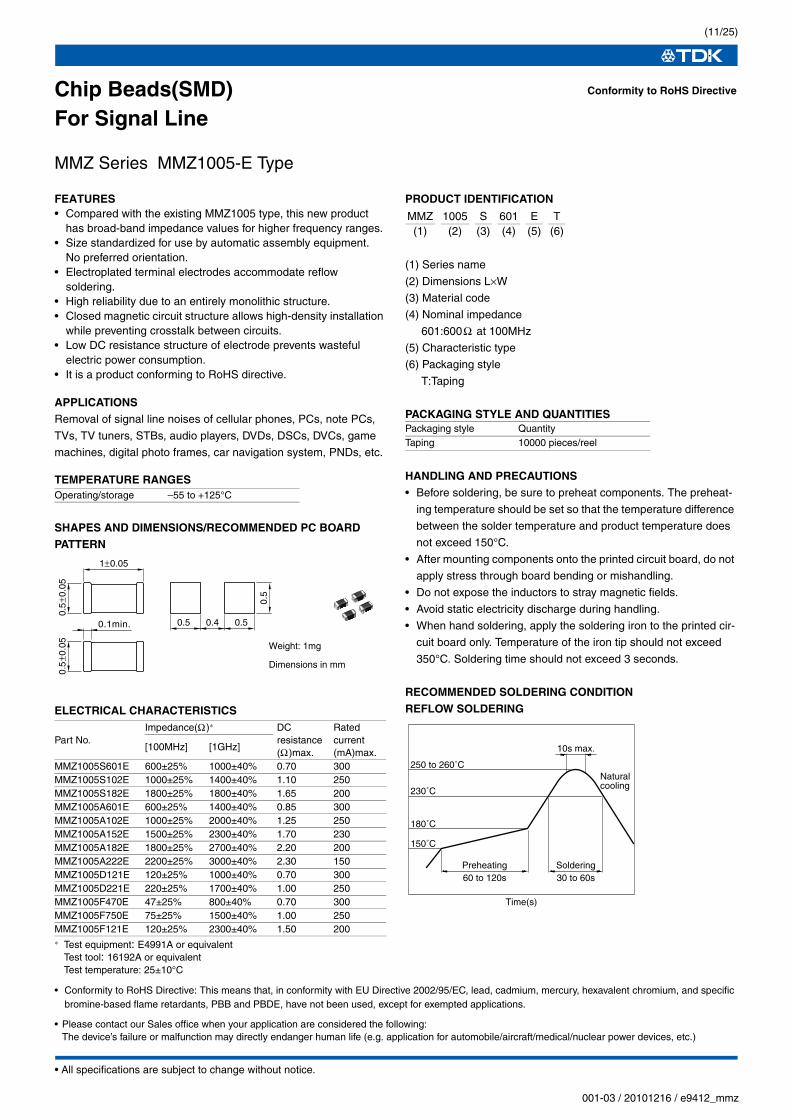
Chip Beads(SMD)For Signal Line
MMZ Series MMZ0402 Type
FEATURES• It is super small size(L0.4×W0.2×T0.2mm).• It prevents radiated noise from high-speed signal lines.• Maintain impedance to high frequency band.• Because it adopts silver in internal electrode, it is low D.C.
resistance.• Because it is not generate of cross talk with closed magnetic cir-
cuit structural design, high density assembly is possible.• It is a product conforming to RoHS directive.
APPLICATIONSRemoval of signal line noises of cellular phones, portable audio
players, various modules, etc.
PRODUCT IDENTIFICATION
(1) Series name(2) Dimensions L×W(3) Material code(4) Nominal impedance
121:120Ω at 100MHz
(5) Characteristic type(6) Packaging style
T: Taping
HANDLING AND PRECAUTIONS• Before soldering, be sure to preheat components. The preheat-
ing temperature should be set so that the temperature difference
between the solder temperature and product temperature does
not exceed 150°C.
• After mounting components onto the printed circuit board, do not
apply stress through board bending or mishandling.
• Do not expose the inductors to stray magnetic fields.
• Avoid static electricity discharge during handling.
SHAPES AND DIMENSIONS/RECOMMENDED PC BOARD PATTERN
TEMPERATURE RANGES
PACKAGING STYLE AND QUANTITIES
RECOMMENDED SOLDERING CONDITIONREFLOW SOLDERING
ELECTRICAL CHARACTERISTICS
∗ Test equipment: E4991A or equivalentTest tool: 16197 or equivalentTest temperature: 25±10°C
• Please contact our Sales office when your application are considered the following:The device’s failure or malfunction may directly endanger human life (e.g. application for automobile/aircraft/medical/nuclear power devices, etc.)
• Conformity to RoHS Directive: This means that, in conformity with EU Directive 2002/95/EC, lead, cadmium, mercury, hexavalent chromium, and specific bromine-based flame retardants, PBB and PBDE, have not been used, except for exempted applications.
• All specifications are subject to change without notice.
(2/25)
001-03 / 20101216 / e9412_mmz
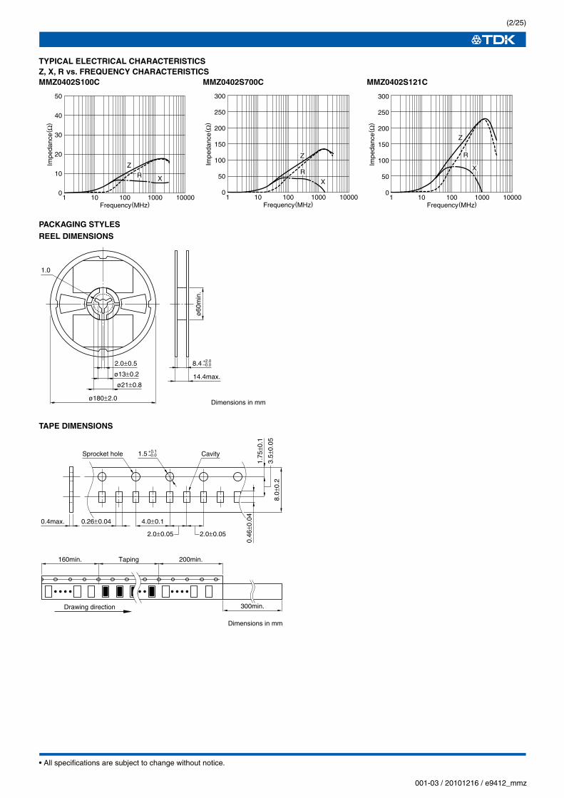
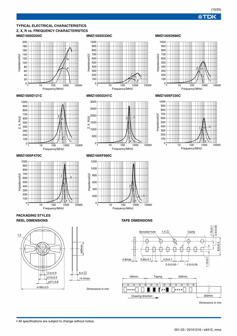
TYPICAL ELECTRICAL CHARACTERISTICSZ, X, R vs. FREQUENCY CHARACTERISTICSMMZ0402S100C MMZ0402S700C MMZ0402S121C
PACKAGING STYLESREEL DIMENSIONS
TAPE DIMENSIONS
0
300
250
150
200
100
50
100001000100101
Impe
danc
e( Ω
)Frequency(MHz)
Z
R
X
0
50
40
30
20
10
100001000100101
Impe
danc
e( Ω
)
Frequency(MHz)
Z
R X
100001000100101Frequency(MHz)
Z
R
X
0
300
250
150
200
100
50
Impe
danc
e( Ω
)
1.0
ø180±2.0
2.0±0.5
ø13±0.2
ø21±0.8
ø60
min
.
14.4max.
Dimensions in mm
8.4 +2.0–0.0
8.0±
0.2
3.5±
0.05
0.46
±0.0
4
1.75
±0.1
0.4max. 0.26±0.04 4.0±0.1
2.0±0.05 2.0±0.05
Sprocket hole Cavity1.5 +0.1–0.0
160min. Taping 200min.
300min.Drawing direction
Dimensions in mm
• All specifications are subject to change without notice.
(3/25)
001-03 / 20101216 / e9412_mmz
Chip Beads(SMD)For Signal Line
MMZ Series MMZ0603 Type
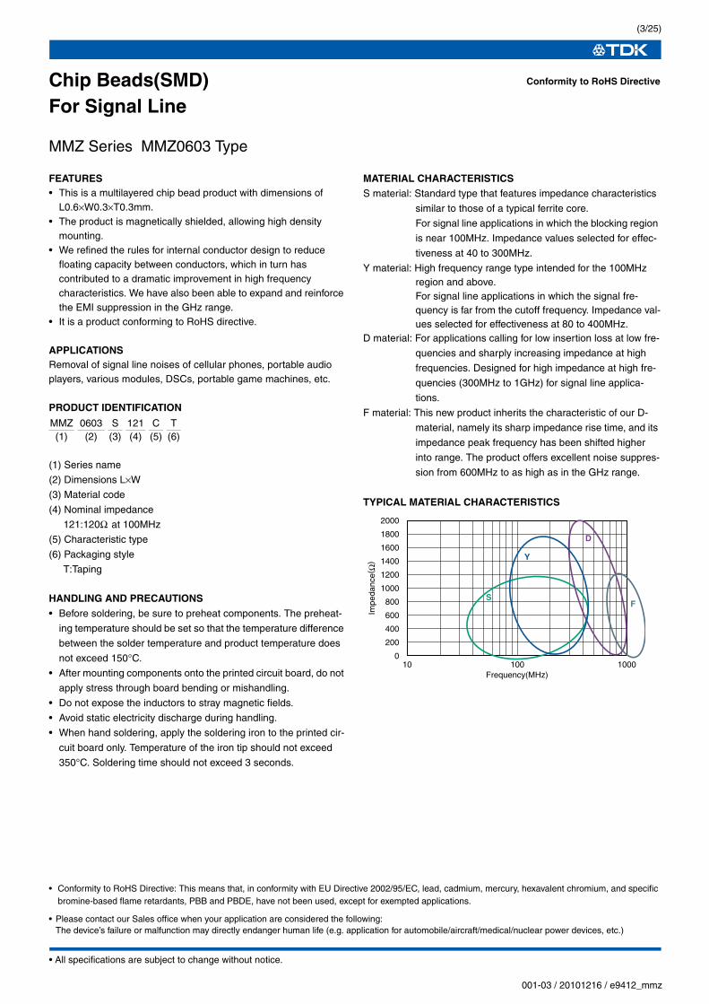
FEATURES• This is a multilayered chip bead product with dimensions of
L0.6×W0.3×T0.3mm.• The product is magnetically shielded, allowing high density
mounting.• We refined the rules for internal conductor design to reduce
floating capacity between conductors, which in turn has contributed to a dramatic improvement in high frequency characteristics. We have also been able to expand and reinforce the EMI suppression in the GHz range.
• It is a product conforming to RoHS directive.
APPLICATIONSRemoval of signal line noises of cellular phones, portable audio players, various modules, DSCs, portable game machines, etc.
PRODUCT IDENTIFICATION
(1) Series name
(2) Dimensions L×W
(3) Material code
(4) Nominal impedance
121:120Ω at 100MHz
(5) Characteristic type
(6) Packaging style
T:Taping
HANDLING AND PRECAUTIONS• Before soldering, be sure to preheat components. The preheat-
ing temperature should be set so that the temperature difference
between the solder temperature and product temperature does
not exceed 150°C.
• After mounting components onto the printed circuit board, do not
apply stress through board bending or mishandling.
• Do not expose the inductors to stray magnetic fields.
• Avoid static electricity discharge during handling.
• When hand soldering, apply the soldering iron to the printed cir-
cuit board only. Temperature of the iron tip should not exceed
350°C. Soldering time should not exceed 3 seconds.
MATERIAL CHARACTERISTICSS material: Standard type that features impedance characteristics
similar to those of a typical ferrite core.
For signal line applications in which the blocking region
is near 100MHz. Impedance values selected for effec-
tiveness at 40 to 300MHz.
Y material: High frequency range type intended for the 100MHz region and above.For signal line applications in which the signal fre-quency is far from the cutoff frequency. Impedance val-ues selected for effectiveness at 80 to 400MHz.
D material: For applications calling for low insertion loss at low fre-
quencies and sharply increasing impedance at high
frequencies. Designed for high impedance at high fre-
quencies (300MHz to 1GHz) for signal line applica-
tions.
F material: This new product inherits the characteristic of our D-
material, namely its sharp impedance rise time, and its
impedance peak frequency has been shifted higher
into range. The product offers excellent noise suppres-
sion from 600MHz to as high as in the GHz range.
TYPICAL MATERIAL CHARACTERISTICS
Conformity to RoHS Directive
MMZ 0603 S 121 C T(1) (2) (3) (4) (5) (6)
0
200
400
600
800
1000
1200
1400
1600
1800
2000
10 100 1000Frequency(MHz)
Impe
danc
e(Ω
)
S
D
F
Y
• Please contact our Sales office when your application are considered the following:The device’s failure or malfunction may directly endanger human life (e.g. application for automobile/aircraft/medical/nuclear power devices, etc.)
• Conformity to RoHS Directive: This means that, in conformity with EU Directive 2002/95/EC, lead, cadmium, mercury, hexavalent chromium, and specific bromine-based flame retardants, PBB and PBDE, have not been used, except for exempted applications.
• All specifications are subject to change without notice.
(4/25)
001-03 / 20101216 / e9412_mmz
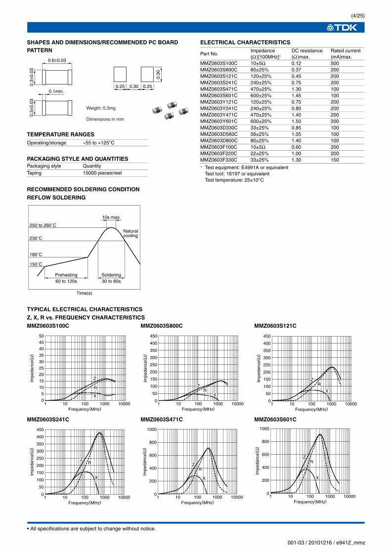
SHAPES AND DIMENSIONS/RECOMMENDED PC BOARD PATTERN
TEMPERATURE RANGES
PACKAGING STYLE AND QUANTITIES
RECOMMENDED SOLDERING CONDITIONREFLOW SOLDERING
ELECTRICAL CHARACTERISTICS
∗ Test equipment: E4991A or equivalentTest tool: 16197 or equivalentTest temperature: 25±10°C
TYPICAL ELECTRICAL CHARACTERISTICSZ, X, R vs. FREQUENCY CHARACTERISTICSMMZ0603S100C MMZ0603S800C MMZ0603S121C
• All specifications are subject to change without notice.
(5/25)
001-03 / 20101216 / e9412_mmz
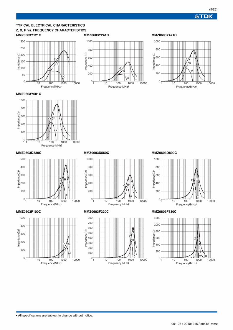
TYPICAL ELECTRICAL CHARACTERISTICSZ, X, R vs. FREQUENCY CHARACTERISTICSMMZ0603Y121C MMZ0603Y241C MMZ0603Y471C
MMZ0603Y601C
MMZ0603D330C MMZ0603D560C MMZ0603D800C
MMZ0603F100C MMZ0603F220C MMZ0603F330C
1 10 100 1000 10000Frequency(MHz)
0
200
400
600
800
1000
Impe
danc
e(Ω
)
Z
X
R
0
50
100
150
200
250
300
Impe
danc
e(Ω
)
1 10 100 1000 10000Frequency(MHz)
Z
X
R
1 10 100 1000 10000Frequency(MHz)
0
200
400
600
800
1000
Impe
danc
e(Ω
)
Z
X
R
1 10 100 1000 10000Frequency(MHz)
0
200
400
600
800
1000
Impe
danc
e(Ω
)
Z
X
R
1 10 100 1000 10000Frequency(MHz)
0
200
400
600
800
1000
Impe
danc
e(Ω
)
Z
X
R
1 10 100 1000 10000Frequency(MHz)
0
100
200
300
400
500
Impe
danc
e(Ω
)
Z
X
R
1 10 100 1000 10000Frequency(MHz)
0
200
400
600
800
1000
Impe
danc
e(Ω
)
Z
X
R
1 10 100 1000 10000Frequency(MHz)
0
100
200
300
400
500
600
700
800
Impe
danc
e(Ω
)
Z
X
R
1 10 100 1000 10000Frequency(MHz)
0
100
200
300
400
500
Impe
danc
e(Ω
)
Z
X
R
1 10 100 1000 10000Frequency(MHz)
0
200
400
600
800
1000
1200
Impe
danc
e(Ω
)
Z
X R
• All specifications are subject to change without notice.
(6/25)
001-03 / 20101216 / e9412_mmz
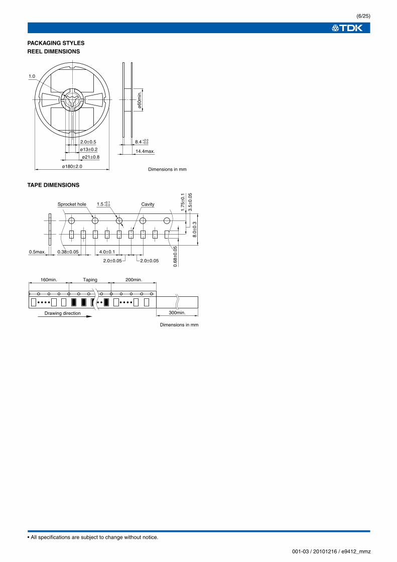
PACKAGING STYLESREEL DIMENSIONS
TAPE DIMENSIONS
1.0
ø180±2.0
2.0±0.5
ø13±0.2
ø21±0.8
ø60
min
.
14.4max.
Dimensions in mm
8.4 +2.0–0.0
8.0±
0.3
3.5±
0.05
1.75
±0.1
4.0±0.1
2.0±0.05 2.0±0.05
Sprocket hole Cavity1.5 +0.1–0.0
0.5max. 0.38±0.05
0.68
±0.0
5
160min. Taping 200min.
300min.Drawing direction
Dimensions in mm
• All specifications are subject to change without notice.
(7/25)
001-03 / 20101216 / e9412_mmz
Chip Beads(SMD)For Signal Line
MMZ Series MMZ1005 Type
FEATURES• Size standardized for use by automatic assembly equipment.
No preferred orientation.• Electroplated terminal electrodes accommodate reflow
soldering.• High reliability due to an entirely monolithic structure.• Closed magnetic circuit structure allows high-density installation
while preventing crosstalk between circuits.• Low DC resistance structure of electrode prevents wasteful
electric power consumption.• It is a product conforming to RoHS directive.
APPLICATIONSRemoval of signal line noises of cellular phones, PCs, note PCs,
TVs, TV tuners, STBs, audio players, DVDs, DSCs, DVCs, game
machines, digital photo frames, car navigation system, PNDs, etc.
PRODUCT IDENTIFICATION
(1) Series name
(2) Dimensions L×W
(3) Material code
(4) Nominal impedance
121:120Ω at 100MHz
(5) Characteristic type
(6) Packaging style
T:Taping
HANDLING AND PRECAUTIONS• Before soldering, be sure to preheat components. The preheat-
ing temperature should be set so that the temperature difference
between the solder temperature and product temperature does
not exceed 150°C.
• After mounting components onto the printed circuit board, do not
apply stress through board bending or mishandling.
• Do not expose the inductors to stray magnetic fields.
• Avoid static electricity discharge during handling.
• When hand soldering, apply the soldering iron to the printed cir-
cuit board only. Temperature of the iron tip should not exceed
350°C. Soldering time should not exceed 3 seconds.
MATERIAL CHARACTERISTICSB material: This type is perfectly suited for fast digital signals. By
equalizing R components and X components that
beads possess at a frequency of 5MHz, it is able to
suppress overshooting, undershooting and ringing of
fast digital signals.
S material: Standard type that features impedance characteristics
similar to those of a typical ferrite core.
For signal line applications in which the blocking region
is near 100MHz. Impedance values selected for effec-
tiveness at 40 to 300MHz.
Y material: High frequency range type intended for the 100MHz region and above.For signal line applications in which the signal fre-quency is far from the cutoff frequency. Impedance val-ues selected for effectiveness at 80 to 400MHz.
D material: For applications calling for low insertion loss at low fre-
quencies and sharply increasing impedance at high
frequencies. Designed for high impedance at high fre-
quencies (300MHz to 1GHz) for signal line applica-
tions.
F material: This new product inherits the characteristic of our D-
material, namely its sharp impedance rise time, and its
impedance peak frequency has been shifted higher
into range. The product offers excellent noise suppres-
sion from 600MHz to as high as in the GHz range.
TYPICAL MATERIAL CHARACTERISTICS
Conformity to RoHS Directive
MMZ 1005 S 121 C T
(1) (2) (3) (4) (5) (6)
B
S
D
Y
0
200
400
600
800
1000
1200
1400
1600
1800
2000
10 100 1000Frequency(MHz)
Impe
danc
e(Ω
)
F
• Please contact our Sales office when your application are considered the following:The device’s failure or malfunction may directly endanger human life (e.g. application for automobile/aircraft/medical/nuclear power devices, etc.)
• Conformity to RoHS Directive: This means that, in conformity with EU Directive 2002/95/EC, lead, cadmium, mercury, hexavalent chromium, and specific bromine-based flame retardants, PBB and PBDE, have not been used, except for exempted applications.
• All specifications are subject to change without notice.
(8/25)
001-03 / 20101216 / e9412_mmz
SHAPES AND DIMENSIONS/RECOMMENDED PC BOARD PATTERN
TEMPERATURE RANGES
PACKAGING STYLE AND QUANTITIES
RECOMMENDED SOLDERING CONDITIONREFLOW SOLDERING
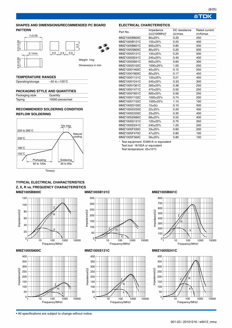
ELECTRICAL CHARCTERISTICS
∗ Test equipment: E4991A or equivalentTest tool: 16192A or equivalentTest temperature: 25±10°C
TYPICAL ELECTRICAL CHARACTERISTICSZ, X, R vs. FREQUENCY CHARACTERISTICSMMZ1005B800C MMZ1005B121C MMZ1005B601C
• Please contact our Sales office when your application are considered the following:The device’s failure or malfunction may directly endanger human life (e.g. application for automobile/aircraft/medical/nuclear power devices, etc.)
• Conformity to RoHS Directive: This means that, in conformity with EU Directive 2002/95/EC, lead, cadmium, mercury, hexavalent chromium, and specific bromine-based flame retardants, PBB and PBDE, have not been used, except for exempted applications.
• All specifications are subject to change without notice.
(12/25)
001-03 / 20101216 / e9412_mmz
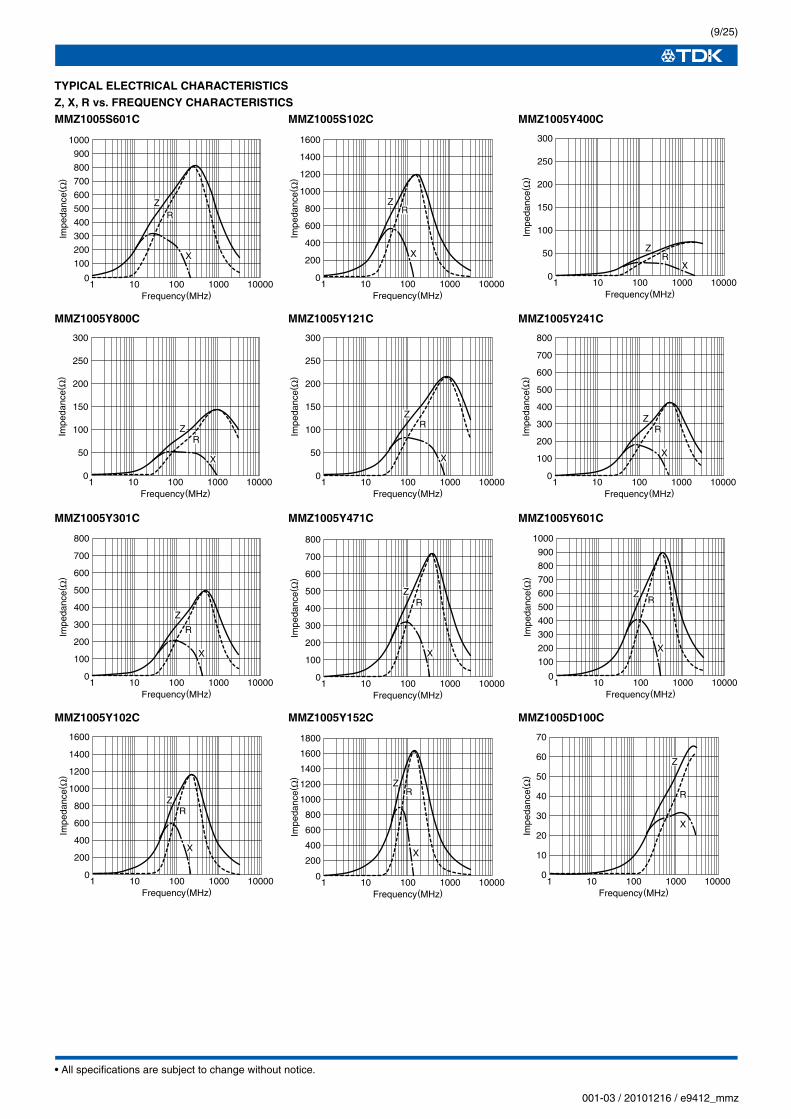
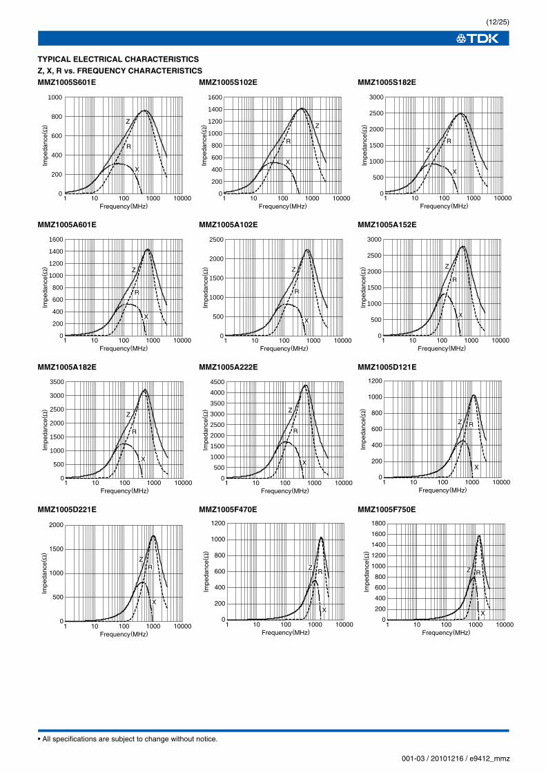
TYPICAL ELECTRICAL CHARACTERISTICSZ, X, R vs. FREQUENCY CHARACTERISTICSMMZ1005S601E MMZ1005S102E MMZ1005S182E
MMZ1005A601E MMZ1005A102E MMZ1005A152E
MMZ1005A182E MMZ1005A222E MMZ1005D121E
MMZ1005D221E MMZ1005F470E MMZ1005F750E
1 10 100 1000 10000Frequency(MHz)
Impe
danc
e(Ω
)
0
200
400
600
800
1000
Z
R
X
1 10 100 1000 10000Frequency(MHz)
Impe
danc
e(Ω
) Z
R
X
0
200
400
600
800
1000
1200
1400
1600
1 10 100 1000 10000Frequency(MHz)
Impe
danc
e(Ω
)
0
500
1000
1500
2000
3000
2500
ZR
X
1 10 100 1000 10000Frequency(MHz)
Impe
danc
e(Ω
)
0
500
1000
1500
2000
2500
3000
Z
R
X
1 10 100 1000 10000Frequency(MHz)
Impe
danc
e(Ω
) Z
R
X
0
200
400
600
800
1000
1200
1400
1600
1 10 100 1000 10000Frequency(MHz)
Impe
danc
e(Ω
)
0
500
1000
1500
2000
2500
Z
R
X
1 10 100 1000 10000Frequency(MHz)
Impe
danc
e(Ω
)
0
500
1000
1500
2000
3500
3000
2500Z
R
X
1 10 100 1000 10000Frequency(MHz)
Impe
danc
e(Ω
)
0
500
1000
1500
2000
4500
3500
3000
4000
2500
Z
R
X
1 10 100 1000 10000Frequency(MHz)
Impe
danc
e(Ω
)
0
200
400
600
800
1000
1200
Z R
X
1 10 100 1000 10000Frequency(MHz)
Impe
danc
e(Ω
)
ZR
X
0
500
1000
1500
2000
1 10 100 1000 10000Frequency(MHz)
Impe
danc
e(Ω
)
0
200
400
600
800
1000
1200
ZR
X
1 10 100 1000 10000Frequency(MHz)
Impe
danc
e(Ω
)
0
200
400
600
800
1000
1200
1400
1600
1800
Z R
X
• All specifications are subject to change without notice.
(13/25)
001-03 / 20101216 / e9412_mmz
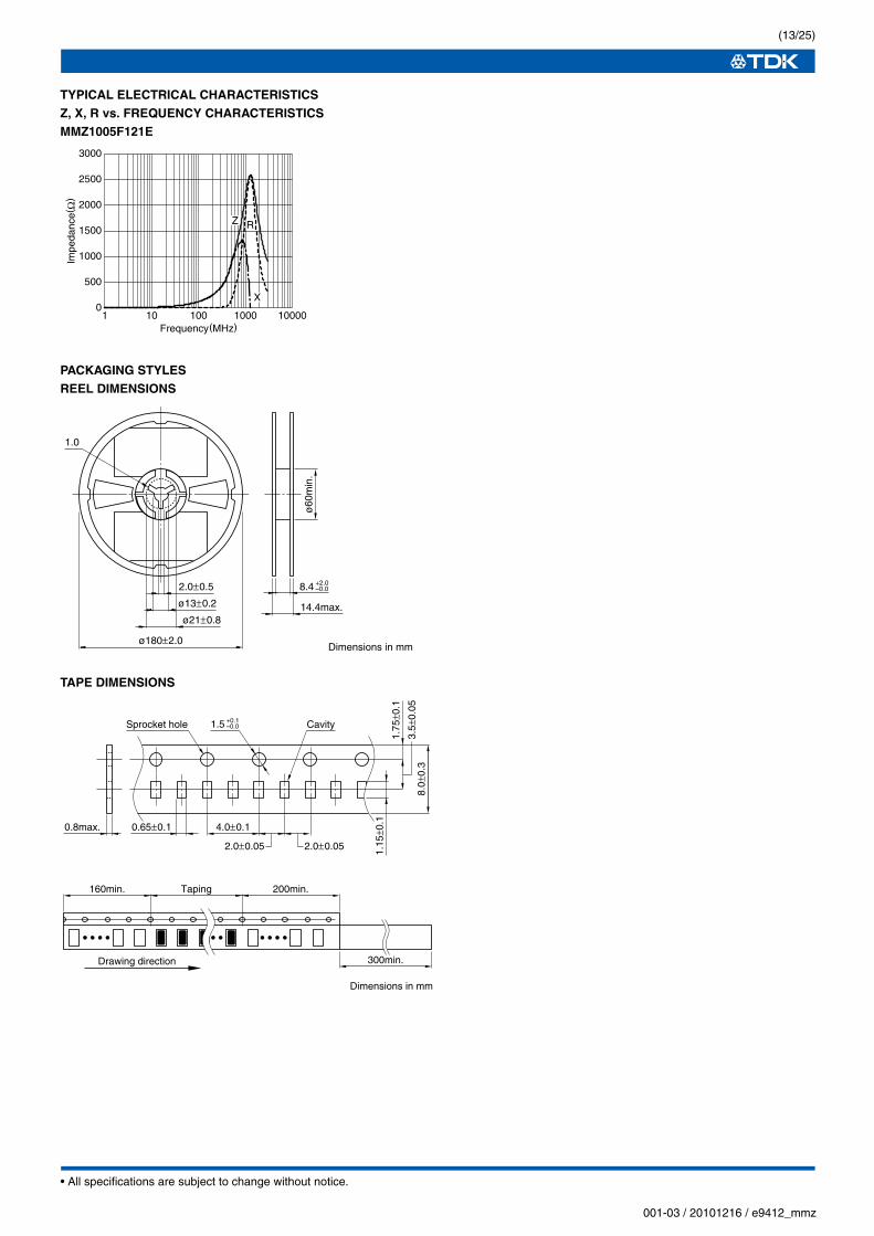
TYPICAL ELECTRICAL CHARACTERISTICSZ, X, R vs. FREQUENCY CHARACTERISTICSMMZ1005F121E
PACKAGING STYLESREEL DIMENSIONS
TAPE DIMENSIONS
1 10 100 1000 10000Frequency(MHz)
Impe
danc
e(Ω
)
0
500
1000
1500
2000
2500
3000
Z R
X
1.0
ø180±2.0
2.0±0.5
ø13±0.2
ø21±0.8
ø60
min
.
14.4max.
Dimensions in mm
8.4 +2.0–0.0
1.15
±0.1
0.8max. 0.65±0.1
8.0±
0.3
3.5±
0.05
1.75
±0.1
4.0±0.1
2.0±0.05 2.0±0.05
Sprocket hole Cavity1.5 +0.1–0.0
160min. Taping 200min.
300min.Drawing direction
Dimensions in mm
• All specifications are subject to change without notice.
(14/25)
001-03 / 20101216 / e9412_mmz
Chip Beads(SMD)For Signal Line
MMZ Series MMZ1608 Type
FEATURES• Chip bead(impeder), MMZ series offers 7 construction materials.
• Size standardized for use by automatic assembly equipment.
No preferred orientation.
• Either flow or reflow soldering methods can be used due to
electroplating of the terminal electrodes.
• High reliability due to an entirely monolithic structure.
• Closed magnetic circuit structure allows high-density installation
while preventing crosstalk between circuits.
• Low DC resistance structure of electrode prevents wasteful
electric power consumption.
• The products contain no lead and also support lead-free
soldering.
• It is a product conforming to RoHS directive.
APPLICATIONSRemoval of signal line noises of cellular phones, PCs, note PCs,
TVs, TV tuners, STBs, audio players, DVDs, DSCs, DVCs, game
machines, digital photo frames, car navigation system, PNDs, etc.
PRODUCT IDENTIFICATION
(1) Series name
(2) Dimensions L×W
(3) Material code
(4) Nominal impedance
121:120Ω at 100MHz
(5) Characteristic type
(6) Packaging style
T:Taping
HANDLING AND PRECAUTIONS• Before soldering, be sure to preheat components. The preheat-
ing temperature should be set so that the temperature difference
between the solder temperature and product temperature does
not exceed 150°C.
• After mounting components onto the printed circuit board, do not
apply stress through board bending or mishandling.
• Do not expose the inductors to stray magnetic fields.
• Avoid static electricity discharge during handling.
• When hand soldering, apply the soldering iron to the printed cir-
cuit board only. Temperature of the iron tip should not exceed
350°C. Soldering time should not exceed 3 seconds.
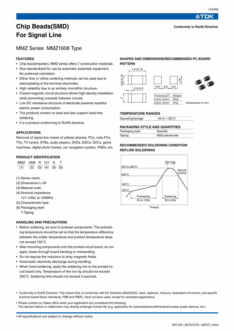
SHAPES AND DIMENSIONS/RECOMMENDED PC BOARDPATTERN
TEMPERATURE RANGES
PACKAGING STYLE AND QUANTITIES
RECOMMENDED SOLDERING CONDITIONREFLOW SOLDERING
Conformity to RoHS Directive
MMZ 1608 R 121 A T
(1) (2) (3) (4) (5) (6)
Operating/storage –55 to +125°C
Packaging style QuantityTaping 4000 pieces/reel
0.8
±0.1
5T
0.3±0.2
1.6±0.15
0.80.6 0.6
0.8
Dimensions in mm
Thickness(T) Weight0.6±0.15mm0.8±0.15mm
3mg4mg
Naturalcooling
10s max.
Preheating60 to 120s
Soldering30 to 60s
230˚C
250 to 260˚C
180˚C
150˚C
Time(s)
• Please contact our Sales office when your application are considered the following:The device’s failure or malfunction may directly endanger human life (e.g. application for automobile/aircraft/medical/nuclear power devices, etc.)
• Conformity to RoHS Directive: This means that, in conformity with EU Directive 2002/95/EC, lead, cadmium, mercury, hexavalent chromium, and specific bromine-based flame retardants, PBB and PBDE, have not been used, except for exempted applications.
• All specifications are subject to change without notice.
(15/25)
001-03 / 20101216 / e9412_mmz
MATERIAL CHARACTERISTICSB material: This type is perfectly suited for fast digital signals.
By equalizing R components and X components that
beads possess at a frequency of 5MHz, it is able to
suppress overshooting, undershooting and ringing of
fast digital signals.
R material: For wide frequency applications calling for broad
impedance characteristics.
For digital signal line applications calling requiring
good waveform integrity. Impedance values selected
for effectiveness at 10 to 200MHz.
S material: Standard type that features impedance characteristics
similar to those of a typical ferrite core.
For signal line applications in which the blocking region
is near 100MHz. Impedance values selected for
effectiveness at 40 to 300MHz.
Y material: High frequency range type intended for the 100MHz
region and above.
For signal line applications in which the signal
frequency is far from the cutoff frequency. Impedance
values selected for effectiveness at 80 to 400MHz.
A material: This high-impedance product is based on the
impedance frequency characteristics of our Y-material.
The product offers excellent impedance
characteristics, which is greater than 2500Ω, in the
vicinity of 100MHz range (MMZ1608A252B).
Q material:For high-band applications designed for 100MHz and
above. Impedance values selected for effectiveness at
100 to 800MHz.
D material: For applications calling for low insertion loss at low
frequencies and sharply increasing impedance at high
frequencies. Designed for high impedance at high
frequencies (300MHz to 1GHz) for signal line
applications.
F material: This new product inherits the characteristic of our D-
material, namely its sharp impedance rise time, and its
impedance peak frequency has been shifted higher
into range.
The product offers excellent noise suppression from
600MHz to as high as in the GHz range.
TYPICAL MATERIAL CHARACTERISTICS
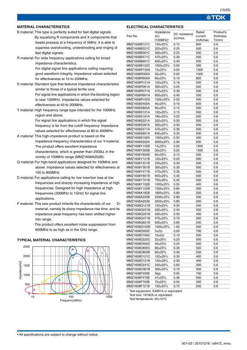
ELECTRICAL CHARACTERISTICS
∗ Test equipment: E4991A or equivalentTest tool: 16192A or equivalentTest temperature: 25±10°C
• All specifications are subject to change without notice.
(16/25)
001-03 / 20101216 / e9412_mmz
TYPICAL ELECTRICAL CHARACTERISTICSZ, X, R vs. FREQUENCY CHARACTERISTICSMMZ1608B121C MMZ1608B221C MMZ1608B301C
MMZ1608B471A MMZ1608B601C MMZ1608B102C
MMZ1608R150A MMZ1608R300A MMZ1608R600A
MMZ1608R121A MMZ1608R301A MMZ1608R471A
1 10 100 1000 10000Frequency(MHz)
Impe
danc
e(Ω
)
Z
R
X
0
50
100
150
200 400
300
200
100
01 10 100 1000 10000
Frequency(MHz)
Impe
danc
e(Ω
)
Z
R
X
0
50
100
150
200
250
300
1 10 100 1000 10000Frequency(MHz)
Impe
danc
e(Ω
)
Z
R
X
800
700
600
500
400
300
200
100
01 10 100 1000 10000
Frequency(MHz)
Impe
danc
e(Ω
)
ZR
X
0
100
200
300
400
500
600
10 100 1000 10000Frequency(MHz)
Impe
danc
e(Ω
)
Z
R
X
0
200
400
600
800
1000
1200
10 100 1000 10000Frequency(MHz)
Impe
danc
e(Ω
) Z
R
X
1 10 100 1000 10000Frequency(MHz)
Impe
danc
e(Ω
)
Z
R
X
0
5
10
15
20
25
30
1 10 100 1000 10000Frequency(MHz)
Impe
danc
e(Ω
)
Z
RX
0
10
20
30
40
50
60 120
40
20
60
80
100
01 10 100 1000 10000
Frequency(MHz)
Impe
danc
e(Ω
)
ZR
X
1 10 100 1000 10000Frequency(MHz)
Impe
danc
e(Ω
)
ZR
X
0
50
100
150
200 400
300
200
100
01 10 100 1000 10000
Frequency(MHz)
Impe
danc
e(Ω
)
Z
R
X
0
100
200
300
400
500
600
10 100 1000 10000Frequency(MHz)
Impe
danc
e(Ω
)
Z
R
X
• All specifications are subject to change without notice.
(17/25)
001-03 / 20101216 / e9412_mmz
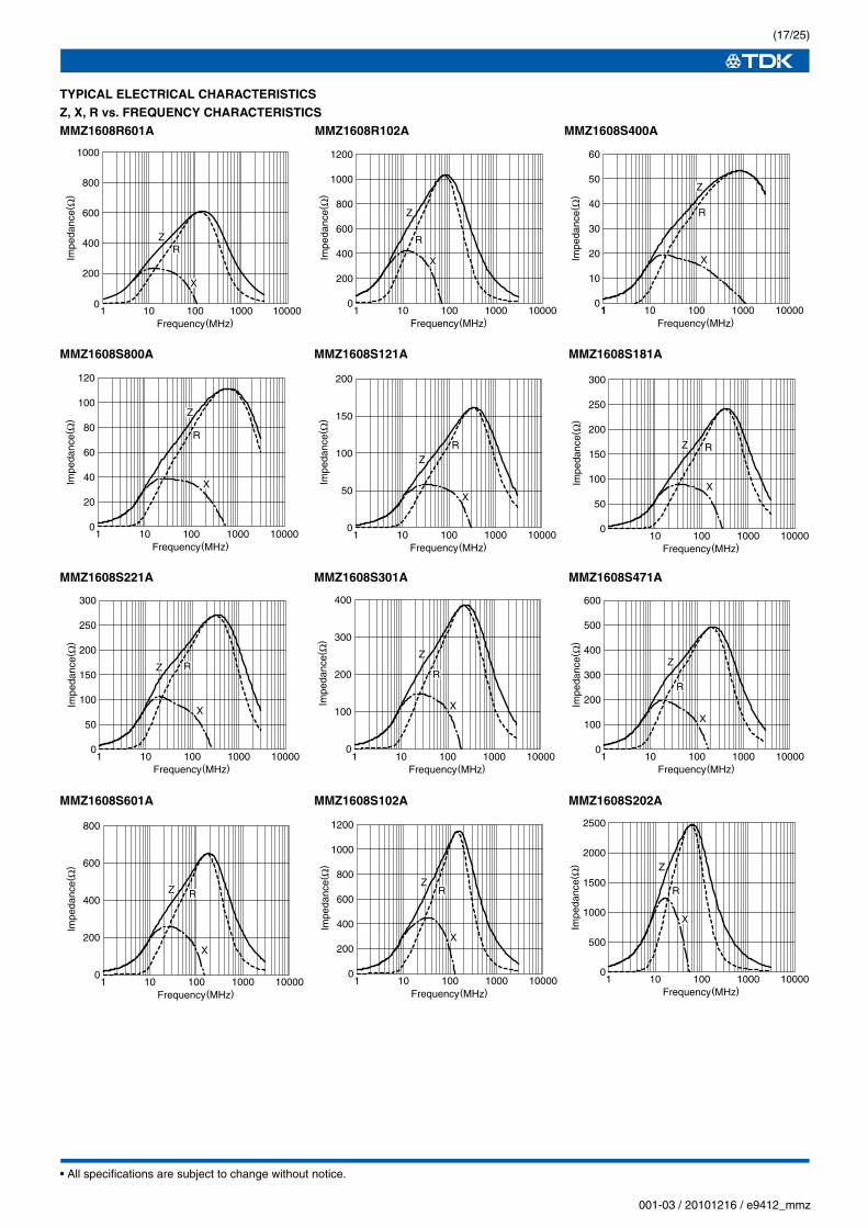
TYPICAL ELECTRICAL CHARACTERISTICSZ, X, R vs. FREQUENCY CHARACTERISTICSMMZ1608R601A MMZ1608R102A MMZ1608S400A
MMZ1608S800A MMZ1608S121A MMZ1608S181A
MMZ1608S221A MMZ1608S301A MMZ1608S471A
MMZ1608S601A MMZ1608S102A MMZ1608S202A
1 10 100 1000 10000Frequency(MHz)
1200
1000
800
600
400
200
0
Impe
danc
e(Ω
)
Z
R
X
1 10 100 1000 10000Frequency(MHz)
1
Impe
danc
e(Ω
)
Z
R
X
0
10
20
30
40
50
601000
800
600
400
200
01 10 100 1000 10000
Frequency(MHz)
Impe
danc
e(Ω
)
ZR
X
1 10 100 1000 10000Frequency(MHz)
200
100
50
150
0
Impe
danc
e(Ω
)
ZR
X
10 100 1000 10000Frequency(MHz)
Impe
danc
e(Ω
)
0
50
100
150
200
250
300
RZ
X
1 10 100 1000 10000Frequency(MHz)
Impe
danc
e(Ω
)
Z
R
X
0
20
40
60
80
100
120
1 10 100 1000 10000Frequency(MHz)
Impe
danc
e(Ω
)
Z
R
X
0
100
200
300
400
0
50
100
150
200
250
300
1 10 100 1000 10000Frequency(MHz)
Impe
danc
e(Ω
)
Z R
X
0
100
200
300
400
500
600
1 10 100 1000 10000Frequency(MHz)
Impe
danc
e(Ω
)
Z
R
X
1 10 100 1000 10000Frequency(MHz)
800
600
400
200
0
Impe
danc
e(Ω
)
X
Z R
1 10 100 1000 10000Frequency(MHz)
1200
1000
800
600
400
200
0
Impe
danc
e(Ω
)
ZR
X
0
500
1000
1500
2000
2500
1 10 100 1000 10000Frequency(MHz)
Impe
danc
e(Ω
) Z
R
X
• All specifications are subject to change without notice.
(18/25)
001-03 / 20101216 / e9412_mmz
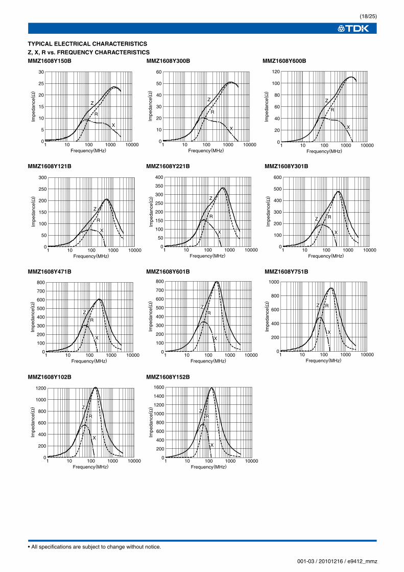
TYPICAL ELECTRICAL CHARACTERISTICSZ, X, R vs. FREQUENCY CHARACTERISTICSMMZ1608Y150B MMZ1608Y300B MMZ1608Y600B
MMZ1608Y121B MMZ1608Y221B MMZ1608Y301B
MMZ1608Y471B MMZ1608Y601B MMZ1608Y751B
MMZ1608Y102B MMZ1608Y152B
1 10 100 1000 10000Frequency(MHz)
Impe
danc
e(Ω
)
Z
R
X
0
10
20
30
40
50
60 120
40
20
60
80
100
01 10 100 1000 10000
Frequency(MHz)
Impe
danc
e(Ω
)
Z
R
X
1 10 100 1000 10000Frequency(MHz)
Impe
danc
e(Ω
)
Z
R
X
0
5
10
15
20
25
30
0
100
200
300
400
500
600
1 10 100 1000 10000Frequency(MHz)
Impe
danc
e(Ω
)
Z R
X
1 10 100 1000 10000Frequency(MHz)
Impe
danc
e(Ω
)
Z
R
X
0
50
100
150
200
250
300
0
50
100
150
200
250
300
350
400
1 10 100 1000 10000Frequency(MHz)
Impe
danc
e(Ω
) Z
R
X
800
700
600
500
400
300
200
100
01 10 100 1000 10000
Frequency(MHz)
Impe
danc
e(Ω
)
ZR
X
0
100
200
300
400
500
600
700
800
1 10 100 1000 10000Frequency(MHz)
Impe
danc
e(Ω
)
Z
R
X
0
200
400
600
800
1000
1 10 100 1000 10000Frequency(MHz)
Impe
danc
e(Ω
)
Z R
X
1600
1400
1200
1000
800
600
400
200
01 10 100 1000 10000
Frequency(MHz)
Impe
danc
e(Ω
)
ZR
X
1 10 100 1000 10000Frequency(MHz)
1200
1000
800
600
400
200
0
Impe
danc
e(Ω
) Z
R
X
• All specifications are subject to change without notice.
(19/25)
001-03 / 20101216 / e9412_mmz
TYPICAL ELECTRICAL CHARACTERISTICSZ, X, R vs. FREQUENCY CHARACTERISTICSMMZ1608A182B MMZ1608A222B MMZ1608A252B
MMZ1608Q121B MMZ1608Q221B MMZ1608Q331B
MMZ1608Q471B MMZ1608Q601B MMZ1608Q102B
MMZ1608D050C MMZ1608D100C MMZ1608D220C
3000
0
500
1000
1500
2000
2500
1 10 100 1000 10000Frequency(MHz)
Impe
danc
e(Ω
)
Z R
X
0
500
1000
1500
2000
1 10 100 1000 10000Frequency(MHz)
Impe
danc
e(Ω
)
Z
R
X
0
500
1000
1500
2000
2500
1 10 100 1000 10000Frequency(MHz)
Impe
danc
e(Ω
)
Z R
X
1 10 100 1000 10000Frequency(MHz)
Impe
danc
e(Ω
)
ZR
X
0
100
200
300
400
500
600400
300
200
100
01 10 100 1000 10000
Frequency(MHz)
Impe
danc
e(Ω
)
Z R
X
0
100
200
300
400
500
600
700
800
1 10 100 1000 10000Frequency(MHz)
Impe
danc
e(Ω
)
Z
R
X
1 10 100 1000 10000Frequency(MHz)
Impe
danc
e(Ω
)
ZR
X
0
500
1000
1500
2000
1 10 100 1000 10000Frequency(MHz)
Impe
danc
e(Ω
) Z
R
X
0
200
400
600
800
1000
1200
1 10 100 1000 10000Frequency(MHz)
Impe
danc
e(Ω
)
Z
R
X
0
200
400
600
800
1000
1200
1400
1600
1 10 100 1000 10000Frequency(MHz)
Impe
danc
e(Ω
)
Z
R
X
0
50
100
150
200100
80
60
40
20
01 10 100 1000 10000
Frequency(MHz)
Impe
danc
e(Ω
)
ZR
X
1 10 100 1000 10000Frequency(MHz)
Impe
danc
e(Ω
)
Z R
X
0
5
10
15
20
25
30
• All specifications are subject to change without notice.
(20/25)
001-03 / 20101216 / e9412_mmz
TYPICAL ELECTRICAL CHARACTERISTICSZ, X, R vs. FREQUENCY CHARACTERISTICSMMZ1608D500C MMZ1608D800C MMZ1608D800B
MMZ1608D121C MMZ1608D121B MMZ1608D241C
MMZ1608D301B MMZ1608F030B MMZ1608F470B
MMZ1608F750B MMZ1608F121B
600
200
100
300
400
500
01 10 100 1000 10000
Frequency(MHz)Im
peda
nce(
Ω)
ZR
X
1 10 100 1000 10000Frequency(MHz)
400
200
100
300
0
Impe
danc
e(Ω
) Z
R
X
800
700
600
500
400
300
200
100
01 10 100 1000 10000
Frequency(MHz)
Impe
danc
e(Ω
)
ZR
X
800
700
600
500
400
300
200
100
01 10 100 1000 10000
Frequency(MHz)
Impe
danc
e(Ω
)
ZR
X
1 10 100 1000 10000Frequency(MHz)
800
700
600
500
400
300
200
100
0
Impe
danc
e(Ω
)
Z
X
R
1200
1000
800
600
400
200
0
Impe
danc
e(Ω
)
1 10 100 1000 10000Frequency(MHz)
Z
X
R
1 10 100 1000 10000Frequency(MHz)
3000
2500
2000
1500
1000
500
0
Impe
danc
e(Ω
)
Z
X
R
0
10
20
30
40
50
1 10 100 1000 10000Frequency(MHz)
Impe
danc
e(Ω
)
Z
RX
0
200
400
600
800
1000
1 10 100 1000 10000Frequency(MHz)
Impe
danc
e(Ω
)
Z
R X
0
500
1000
1500
2000
1 10 100 1000 10000Frequency(MHz)
Impe
danc
e(Ω
)
Z
R X 0
1000
2000
3000
4000
5000
6000
1 10 100 1000 10000Frequency(MHz)
Impe
danc
e(Ω
)
Z
R
X
• All specifications are subject to change without notice.
(21/25)
001-03 / 20101216 / e9412_mmz
PACKAGING STYLESREEL DIMENSIONS
TAPE DIMENSIONS
1.0
ø180±2.0
2.0±0.5
ø13±0.2
ø21±0.8
ø60
min
.
14.4max.
Dimensions in mm
8.4 +2.0–0.0
8.0±
0.3
3.5±
0.05
1.9±
0.2
1.75
±0.1
1.1max. 1.1±0.2 4.0±0.1 4.0±0.1
2.0±0.05
1.5 +0.1–0.0Sprocket hole Cavity
160min. Taping 200min.
300min.Drawing direction
Dimensions in mm
• All specifications are subject to change without notice.
(22/25)
001-03 / 20101216 / e9412_mmz
Chip Beads(SMD)For Signal Line
MMZ Series MMZ2012 Type
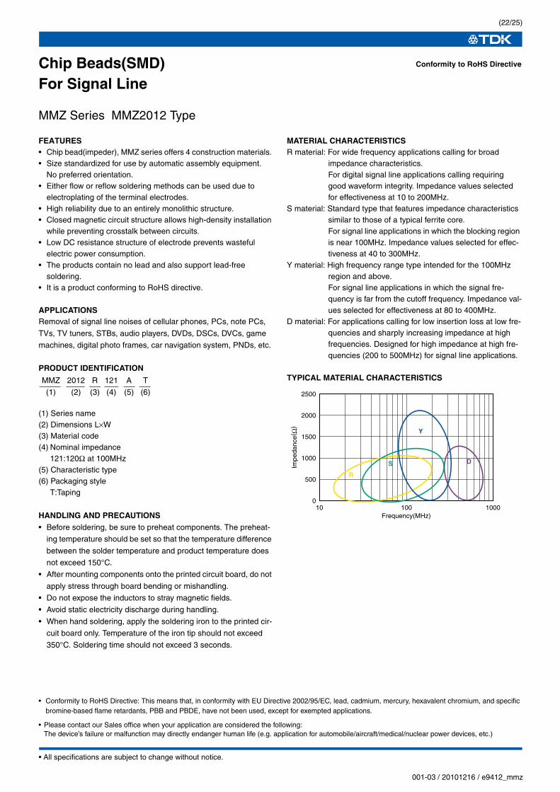
FEATURES• Chip bead(impeder), MMZ series offers 4 construction materials. • Size standardized for use by automatic assembly equipment.
No preferred orientation.• Either flow or reflow soldering methods can be used due to
electroplating of the terminal electrodes.• High reliability due to an entirely monolithic structure.• Closed magnetic circuit structure allows high-density installation
while preventing crosstalk between circuits.• Low DC resistance structure of electrode prevents wasteful
electric power consumption.• The products contain no lead and also support lead-free
soldering.• It is a product conforming to RoHS directive.
APPLICATIONSRemoval of signal line noises of cellular phones, PCs, note PCs,
TVs, TV tuners, STBs, audio players, DVDs, DSCs, DVCs, game
machines, digital photo frames, car navigation system, PNDs, etc.
PRODUCT IDENTIFICATION
(1) Series name(2) Dimensions L×W(3) Material code(4) Nominal impedance
121:120Ω at 100MHz(5) Characteristic type(6) Packaging style
T:Taping
HANDLING AND PRECAUTIONS• Before soldering, be sure to preheat components. The preheat-
ing temperature should be set so that the temperature difference
between the solder temperature and product temperature does
not exceed 150°C.
• After mounting components onto the printed circuit board, do not
apply stress through board bending or mishandling.
• Do not expose the inductors to stray magnetic fields.
• Avoid static electricity discharge during handling.
• When hand soldering, apply the soldering iron to the printed cir-
cuit board only. Temperature of the iron tip should not exceed
350°C. Soldering time should not exceed 3 seconds.
MATERIAL CHARACTERISTICSR material: For wide frequency applications calling for broad
impedance characteristics.For digital signal line applications calling requiring good waveform integrity. Impedance values selected for effectiveness at 10 to 200MHz.
S material: Standard type that features impedance characteristics similar to those of a typical ferrite core.For signal line applications in which the blocking region is near 100MHz. Impedance values selected for effec-tiveness at 40 to 300MHz.
Y material: High frequency range type intended for the 100MHz region and above.For signal line applications in which the signal fre-quency is far from the cutoff frequency. Impedance val-ues selected for effectiveness at 80 to 400MHz.
D material: For applications calling for low insertion loss at low fre-quencies and sharply increasing impedance at high frequencies. Designed for high impedance at high fre-quencies (200 to 500MHz) for signal line applications.
TYPICAL MATERIAL CHARACTERISTICS
Conformity to RoHS Directive
MMZ 2012 R 121 A T
(1) (2) (3) (4) (5) (6)
0
500
1000
1500
2000
2500
10 100 1000Frequency(MHz)
Impe
danc
e(Ω
)
R
S D
Y
• Please contact our Sales office when your application are considered the following:The device’s failure or malfunction may directly endanger human life (e.g. application for automobile/aircraft/medical/nuclear power devices, etc.)
• Conformity to RoHS Directive: This means that, in conformity with EU Directive 2002/95/EC, lead, cadmium, mercury, hexavalent chromium, and specific bromine-based flame retardants, PBB and PBDE, have not been used, except for exempted applications.
• All specifications are subject to change without notice.
(23/25)
001-03 / 20101216 / e9412_mmz
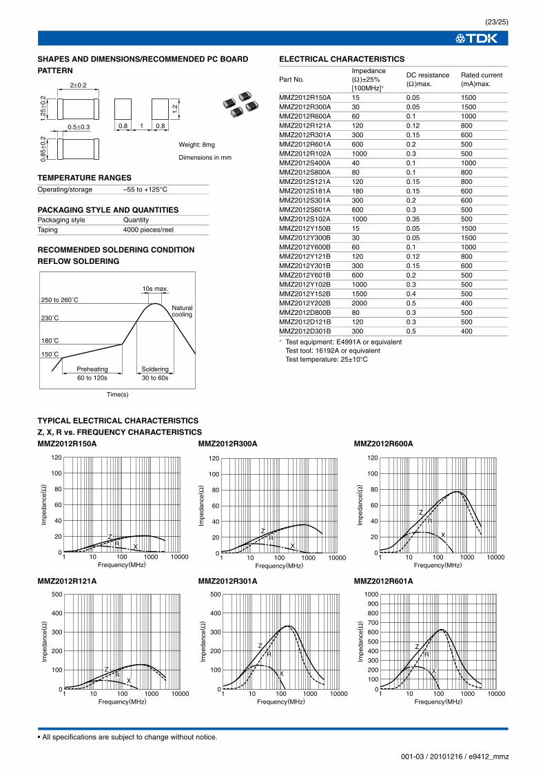
SHAPES AND DIMENSIONS/RECOMMENDED PC BOARD PATTERN
TEMPERATURE RANGES
PACKAGING STYLE AND QUANTITIES
RECOMMENDED SOLDERING CONDITIONREFLOW SOLDERING
ELECTRICAL CHARACTERISTICS
∗ Test equipment: E4991A or equivalentTest tool: 16192A or equivalentTest temperature: 25±10°C
TYPICAL ELECTRICAL CHARACTERISTICSZ, X, R vs. FREQUENCY CHARACTERISTICSMMZ2012R150A MMZ2012R300A MMZ2012R600A