43
Multilayer X-Ray Mirrors & The Extraordinary Swelling of Yttria Thin Films in VUV light. David D. Allred Brigham Young University
Multilayer X-Ray Mirrors & The Extraordinary Swelling of Yttria
Thin Films in VUV light.
David D. Allred Brigham Young University
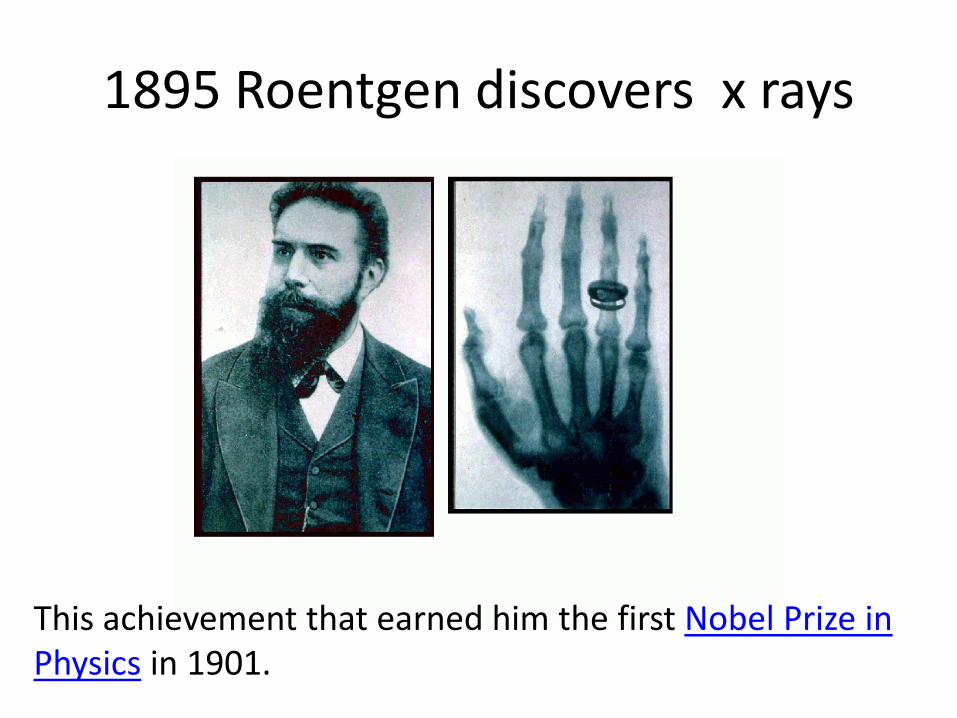
1895 Roentgen discovers x rays
This achievement that earned him the first Nobel Prize in Physics in 1901.
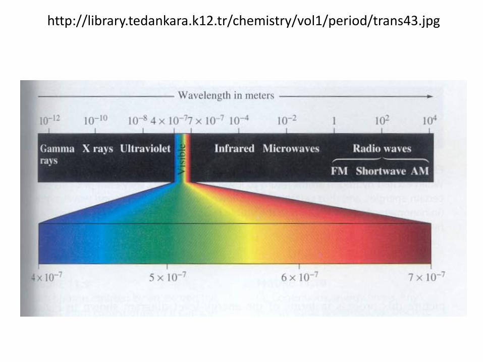
http://library.tedankara.k12.tr/chemistry/vol1/period/trans43.jpg
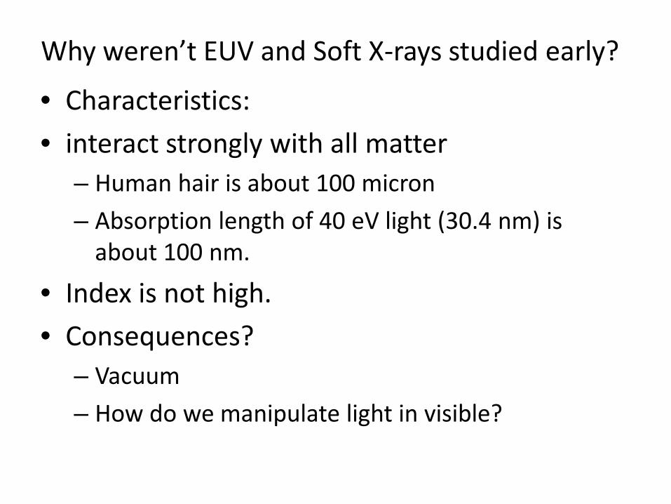
Why weren’t EUV and Soft X-rays studied early?
• Characteristics: • interact strongly with all matter
– Human hair is about 100 micron – Absorption length of 40 eV light (30.4 nm) is
about 100 nm.
• Index is not high. • Consequences?
– Vacuum – How do we manipulate light in visible?

http://users.zoominternet.net/~matto/M.C.A.S/electromagnetic_spectrum.gif
Where do the EUV and Soft X-rays fit?
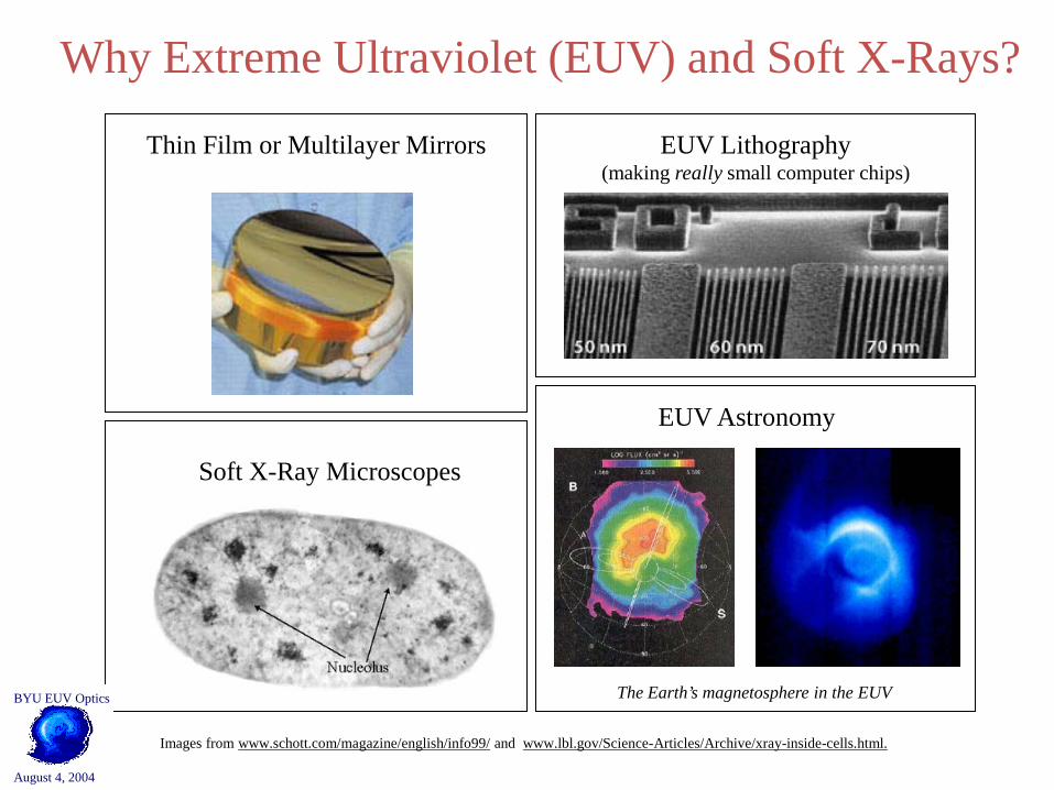
Why Extreme Ultraviolet (EUV) and Soft X-Rays?
Images from www.schott.com/magazine/english/info99/ and www.lbl.gov/Science-Articles/Archive/xray-inside-cells.html.
EUV Lithography (making really small computer chips)
Thin Film or Multilayer Mirrors
EUV Astronomy
The Earth’s magnetosphere in the EUV
Soft X-Ray Microscopes
BYU EUV Optics
August 4, 2004

21 Feb. 2007 7
Our Goal – EUV Applications • Extreme Ultraviolet Optics has
many applications. • These Include:
– EUV Lithography – EUV Astronomy= image mission – Soft X-ray Microscopes
• A Better Understanding of EUV Optics & Materials for EUV applications is needed. – Materials compatible with – Cleaning and storage methods compatible
with Traveling, Modest budgets & Undergraduate
researchers
EUV Lithography
EUV Astronomy
The Earth’s magnetosphere in the EUV
Soft X-ray Microscopes
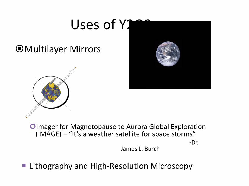
Uses of Y2O3 Multilayer Mirrors
Imager for Magnetopause to Aurora Global Exploration (IMAGE) – “It’s a weather satellite for space storms”
-Dr. James L. Burch
Lithography and High-Resolution Microscopy

21 Feb. 2007 9
Multilayer Mirrors
• Problems – Need constructive interference – Absorption in layers

21 Feb. 2007 10
EUV Multilayer Optics 101 High reflectivity multilayer coatings require:
• Refractive index (n = 1-δ+iβ) contrast at the interfaces: for most materials, these optical constants are not well known in this region.
• Minimal absorption in the low-Z material
• Interfaces which are chemically stable with time
• Minimal interdiffusion at the interfaces
• Thermal stability during illumination
• Chemically stable vacuum interface
Even with the very best designs, multilayer mirrors have only achieved a reflectivity of around 70% in the EUV.
21 Feb. 2007 11
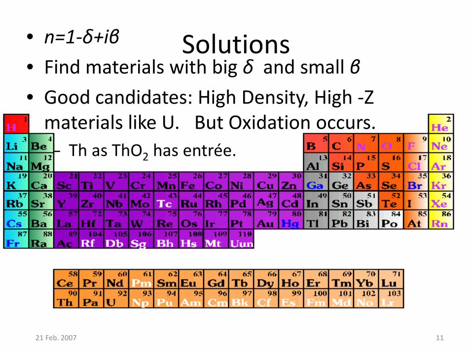
Solutions • n=1-δ+iβ • Find materials with big δ and small β • Good candidates: High Density, High -Z
materials like U. But Oxidation occurs. – Th as ThO2 has entrée.

12
The solution? Research of new materials with these properties
Uranium: Highly reflective in the region from 124-248 eV [1] Not chemically stable with time Uranium Oxide: Highly reflective in the region from 124-248 eV [1] Not chemically stable with time Thorium: Highly reflective in the region from 138-177 eV [2] Not chemically stable with time, tho better than U.
[1] RL Sandberg, DD Allred, JE Johnson, RS Turley, " A Comparison of Uranium Oxide and Nickel as Single-layer Reflectors", Proceedings of the SPIE, Volume 5193, pp. 191-203 (2004).
[2] J. Johnson, D. Allred, R.S. Turley, W. Evans, R. Sandburg, “Thorium-based thin films as highly reflective mirrors in the EUV”, Materials Research Society Symposium Proceedings 893, 207-213, 2006.
21 Feb. 2007 13
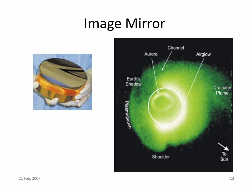
Image Mirror
21 Feb. 2007 14
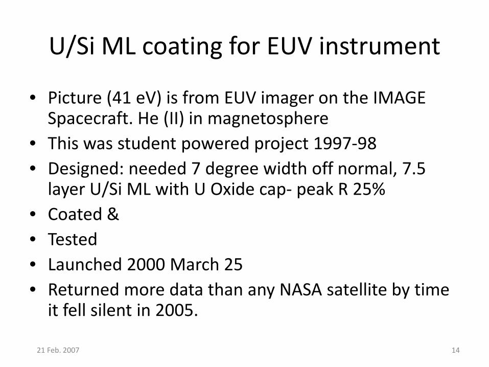
U/Si ML coating for EUV instrument
• Picture (41 eV) is from EUV imager on the IMAGE Spacecraft. He (II) in magnetosphere
• This was student powered project 1997-98 • Designed: needed 7 degree width off normal, 7.5
layer U/Si ML with U Oxide cap- peak R 25% • Coated & • Tested • Launched 2000 March 25 • Returned more data than any NASA satellite by time
it fell silent in 2005.
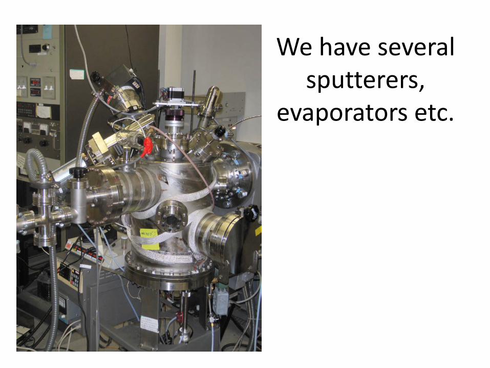
We have several sputterers,
evaporators etc.
21 Feb. 2007 16
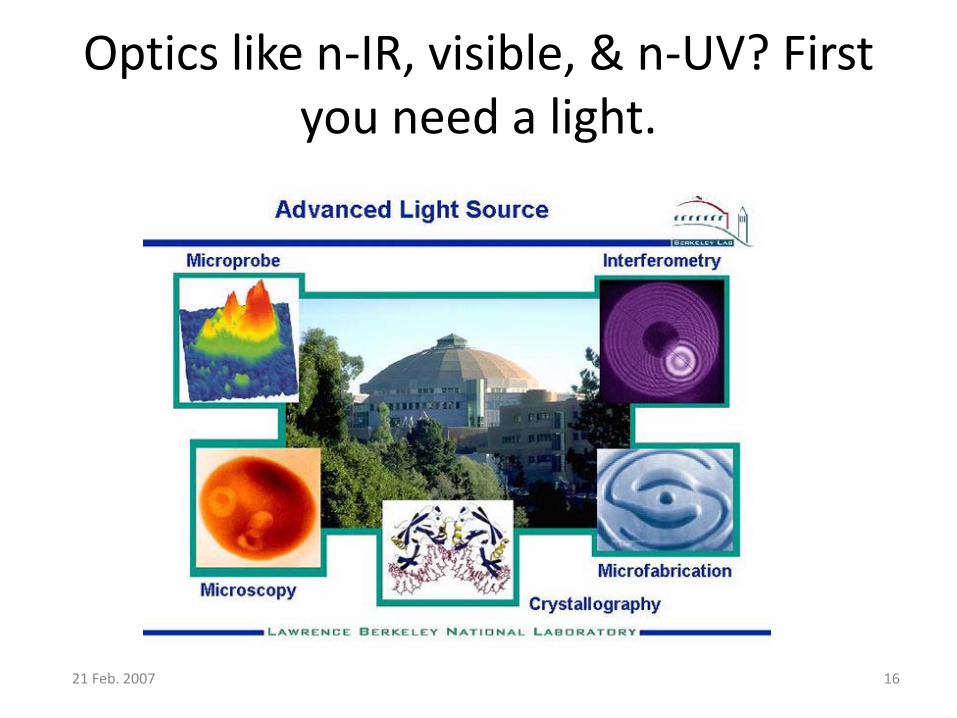
Optics like n-IR, visible, & n-UV? First you need a light.
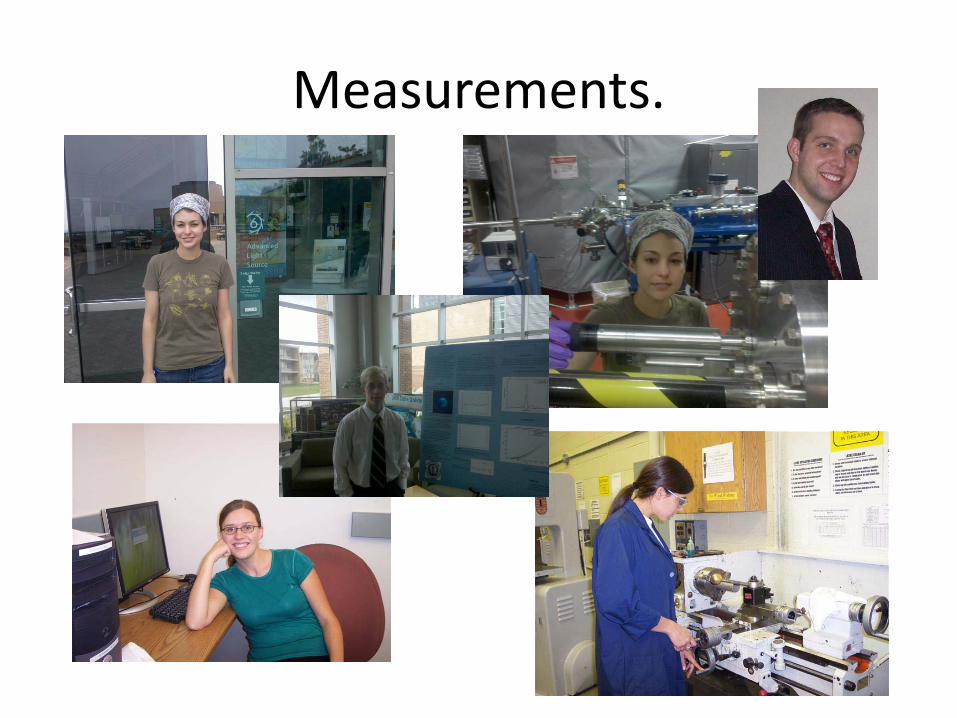
Measurements.
Other Participants • Those who made samples and studied the
strangely expanding film: Alison Wells, Kristal Chamberlain *(Wellesley) , Devon Mortensen*, now U of Washington) Thomas McConkie, Liz Strein (now U of Washington), Brett Bostrom,*
• and The BYU EUV Thin Film Optics Group, past and present who went to ALS : Jacque Jackson, Elise Martin, Lis Strein, Joseph Muhlestein, Megan McGranagain*,
• And made measurements heres Jordan Bell, Heidi Dumais, Greg Hart, Keith Jackson Samuel O. Keller*, Zephne Larsen Vaterlaus*, Victoria Lee, Quintin Nethercott, James Vaterlaus
• R. Steven Turley & David Allred • XPS: Amy B. Grigg
*supported by NSF REU grant PHY0852074.
21 Feb. 2007 18
21 Feb. 2007 19
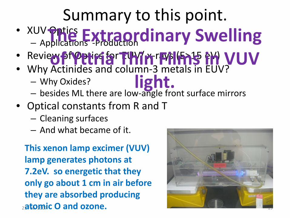
Summary to this point. • XUV Optics
– Applications -Production • Review of Optics for EUV/ x-rays (E>15 eV) • Why Actinides and column-3 metals in EUV?
– Why Oxides? – besides ML there are low-angle front surface mirrors
• Optical constants from R and T – Cleaning surfaces – And what became of it.
This xenon lamp excimer (VUV) lamp generates photons at 7.2eV. so energetic that they only go about 1 cm in air before they are absorbed producing atomic O and ozone.
The Extraordinary Swelling of Yttria Thin Films in VUV
light.
The Setup
• We took some samples to Berkeley for measurements using the Advanced Light Source.
• While there we needed to clean the sample. – Why? Because there is a sort of “gunk” composed
mainly of hydrocarbons that permeates all space and likes to deposit itself on samples.
• Problem: the plasma cleaner was not available to take. • Solution: Let’s use the excimer (VUV) lamp instead. We
had taken it with us. – This lamp generates photons at 7.2eV, which produce O atoms in
air and cleans hydrocarbons from Si wafers.
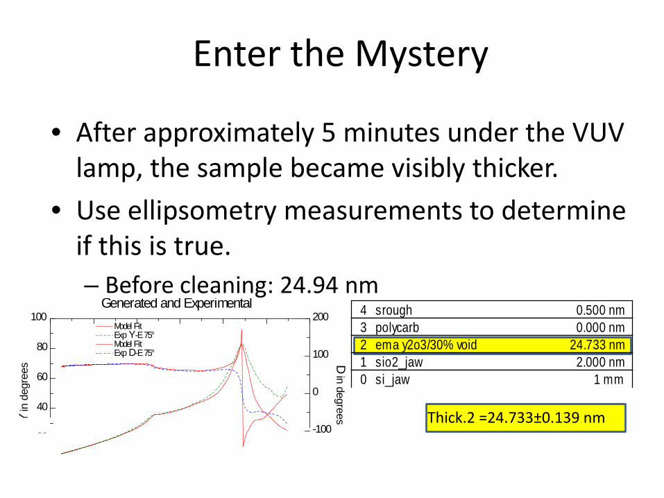
• After approximately 5 minutes under the VUV lamp, the sample became visibly thicker.
• Use ellipsometry measurements to determine if this is true. – Before cleaning: 24.94 nm
0 si_jaw 1 mm1 sio2_jaw 2.000 nm2 ema y2o3/30% void 24.733 nm3 polycarb 0.000 nm4 srough 0.500 nm
Enter the Mystery
Generated and Experimental
Photon Energy (eV)1.0 2.0 3.0 4.0 5.0 6.0 7.0
Y in
deg
rees
D in degrees
0
20
40
60
80
100
-200
-100
0
100
200Model Fit Exp Y-E 75°Model Fit Exp D-E 75°
Thick.2 =24.733±0.139 nm

Ellipsometry Measurements
– After 5 min VUV: 31.061 nm
• As you can see this is quite a significant
change.
Generated and Experimental
Photon Energy (eV)1.0 2.0 3.0 4.0 5.0 6.0
Y in
deg
rees
D in degrees
0
20
40
60
80
100
-100
0
100
200
300Model Fit Exp Y-E 70°Exp Y-E 72°Exp Y-E 74°Exp Y-E 76°Exp Y-E 78°Exp Y-E 80°Model Fit Exp D-E 70°Exp D-E 72°Exp D-E 74°Exp D-E 76°Exp D-E 78°Exp D-E 80°
Thick.2 =31.061±0.0717 nm
24.94 nm 31.06 nm
0 si_jaw 1 mm1 sio2_jaw 1.800 nm2 y2o3 constants based on 091130b on si 31.061 nm3 srough 0.500 nm
0
10
20
30
40
50
60
70
80
90
0 10 20 30 40
Thic
knes
s (n
m)
Time (min)
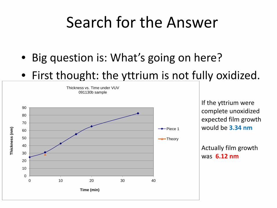
Thickness vs. Time under VUV 091130b sample
Piece 1
Theory
• Big question is: What’s going on here? • First thought: the yttrium is not fully oxidized.
Search for the Answer
If the yttrium were complete unoxidized expected film growth would be 3.34 nm
0
10
20
30
40
50
60
70
80
90
0 10 20 30 40
Thic
knes
s (n
m)
Time (min)
Thickness vs. Time under VUV 091130b sample
Piece 1
Theory
Actually film growth was 6.12 nm
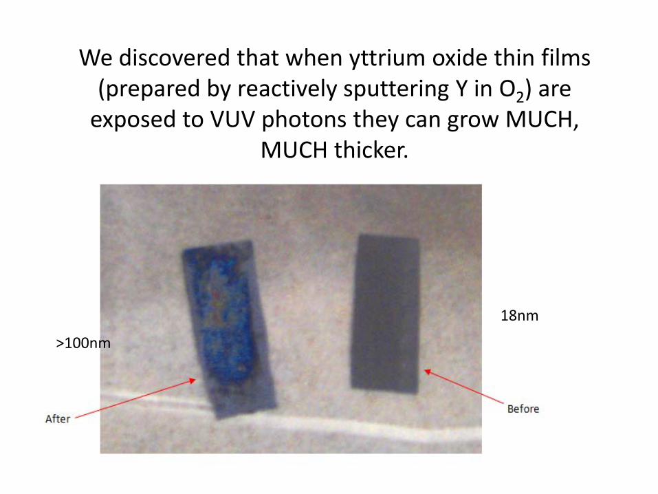
We discovered that when yttrium oxide thin films (prepared by reactively sputtering Y in O2) are
exposed to VUV photons they can grow MUCH, MUCH thicker.
>100nm
18nm
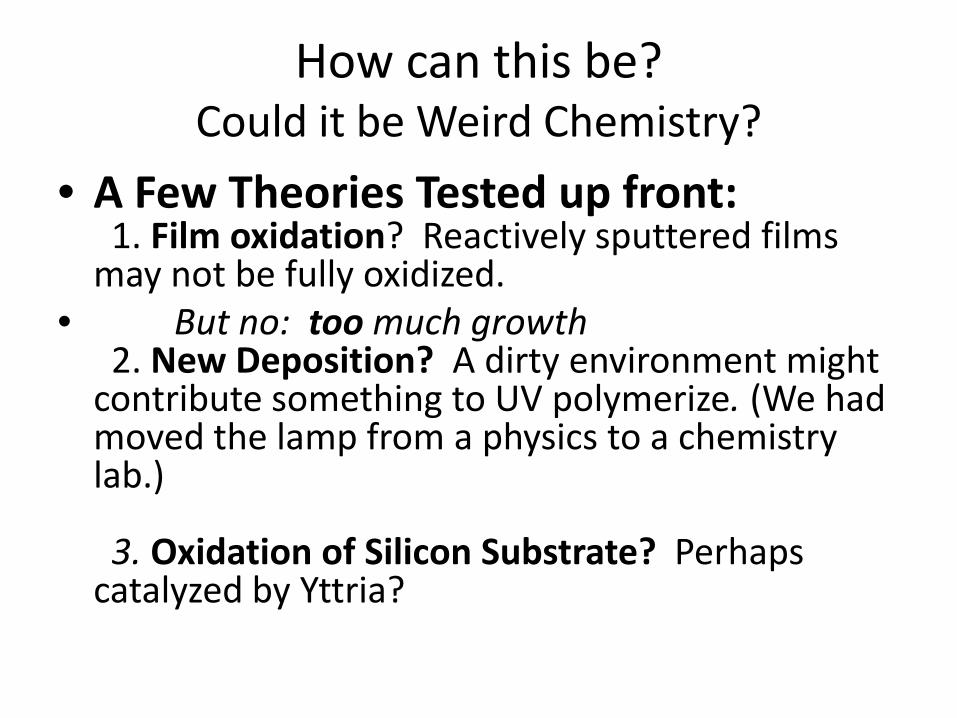
How can this be? Could it be Weird Chemistry?
• A Few Theories Tested up front: 1. Film oxidation? Reactively sputtered films may not be fully oxidized.
• But no: too much growth 2. New Deposition? A dirty environment might contribute something to UV polymerize. (We had moved the lamp from a physics to a chemistry lab.) 3. Oxidation of Silicon Substrate? Perhaps catalyzed by Yttria?

Second Theory
• Is it possible that the VUV lamp is actually depositing material onto the sample? – Not possible that more Y2O3 is being added to
film. – Perhaps it is knocking molecules off of the
support base and these molecules are finding their way to the sample.
• Subject a blank silicon substrate to same VUV treatment and look for film deposition.
Generated and Experimental
Photon Energy (eV)1.0 2.0 3.0 4.0 5.0 6.0 7.0
Y in
deg
rees
D in degrees
0
10
20
30
40
50
0
30
60
90
120
150
180Model Fit Exp Y-E 75°Model Fit Exp D-E 75°
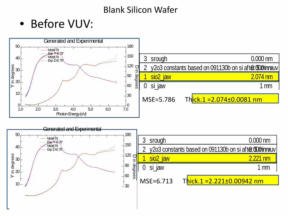
• Before VUV:
• After 5 min VUV:
0 si_jaw 1 mm1 sio2_jaw 2.221 nm2 y2o3 constants based on 091130b on si after 5 min vuv 0.000 nm3 srough 0.000 nm
0 si_jaw 1 mm1 sio2_jaw 2.074 nm2 y2o3 constants based on 091130b on si after 5 min vuv 0.000 nm3 srough 0.000 nm
MSE=5.786 Thick.1 =2.074±0.0081 nm
Generated and Experimental
Photon Energy (eV)1.0 2.0 3.0 4.0 5.0 6.0 7.0
Y in
deg
rees
D in degrees
0
10
20
30
40
50
0
30
60
90
120
150
180Model Fit Exp Y-E 75°Model Fit Exp D-E 75°
MSE=6.713 Thick.1 =2.221±0.00942 nm
Blank Silicon Wafer
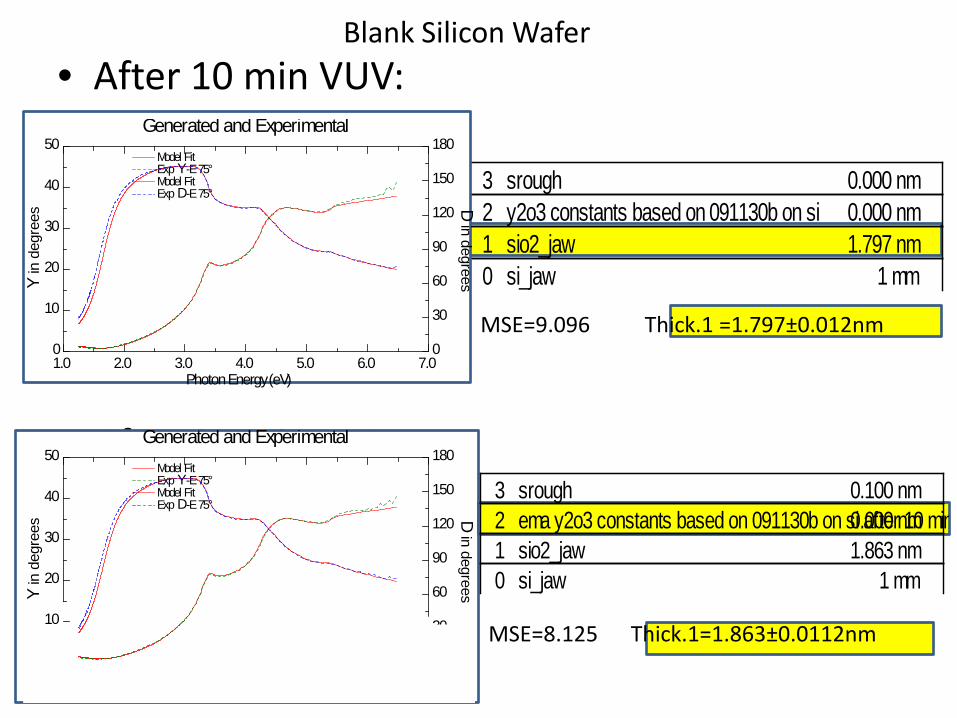
0 si_jaw 1 mm1 sio2_jaw 1.797 nm2 y2o3 constants based on 091130b on si 0.000 nm3 srough 0.000 nm
• After 10 min VUV:
• After 25 min VUV:
Generated and Experimental
Photon Energy (eV)1.0 2.0 3.0 4.0 5.0 6.0 7.0
Y in
deg
rees
D in degrees
0
10
20
30
40
50
0
30
60
90
120
150
180Model Fit Exp Y-E 75°Model Fit Exp D-E 75°
MSE=9.096 Thick.1 =1.797±0.012nm
Generated and Experimental
Photon Energy (eV)1.0 2.0 3.0 4.0 5.0 6.0 7.0
Y in
deg
rees
D in degrees
0
10
20
30
40
50
0
30
60
90
120
150
180Model Fit Exp Y-E 75°Model Fit Exp D-E 75°
0 si_jaw 1 mm1 sio2_jaw 1.863 nm2 ema y2o3 constants based on 091130b on si after 10 min 0.000 nm3 srough 0.100 nm
MSE=8.125 Thick.1=1.863±0.0112nm
Blank Silicon Wafer
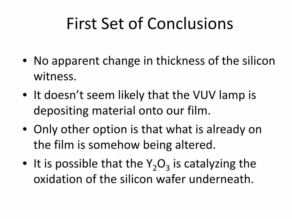
First Set of Conclusions
• No apparent change in thickness of the silicon witness.
• It doesn’t seem likely that the VUV lamp is depositing material onto our film.
• Only other option is that what is already on the film is somehow being altered.
• It is possible that the Y2O3 is catalyzing the oxidation of the silicon wafer underneath.
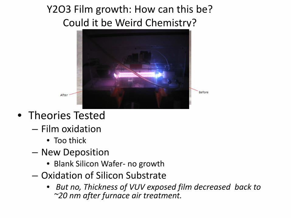
Y2O3 Film growth: How can this be? Could it be Weird Chemistry?
• Theories Tested – Film oxidation
• Too thick – New Deposition
• Blank Silicon Wafer- no growth – Oxidation of Silicon Substrate
• But no, Thickness of VUV exposed film decreased back to ~20 nm after furnace air treatment.
Other data & questions: 1. Are there other techniques which will also produce the increase in thickness? Not that we found. Samples which were plasma cleaned or furnace cleaned did not grow thicker and in some cases if they had been plasma cleaned the sample did not increase in thickness when subsequently exposed to VUV light. 2. Do other oxides show the same effect? We tried reactively sputtered scandium (Sc2O3) which is right above Y in the periodic table. At first nothing. And later with newly prepared samples found that it did. 3. Also yttrium oxide prepared by RF sputtering of Y2O3 was not observed to expand when exposed to VUV.
Other observations:
As the thickness goes up the index of refraction (as measured via ellipsometry) goes down. It starts at about 1.6 and goes down to less than SiO2 which has one of the lowest indices of any oxide.
The films become increasingly delicate as they get thicker. They are easily scratched and flaky. The thickness increase is less around the edges of the substrate. See the arrow on the figure and note the blotchiness.
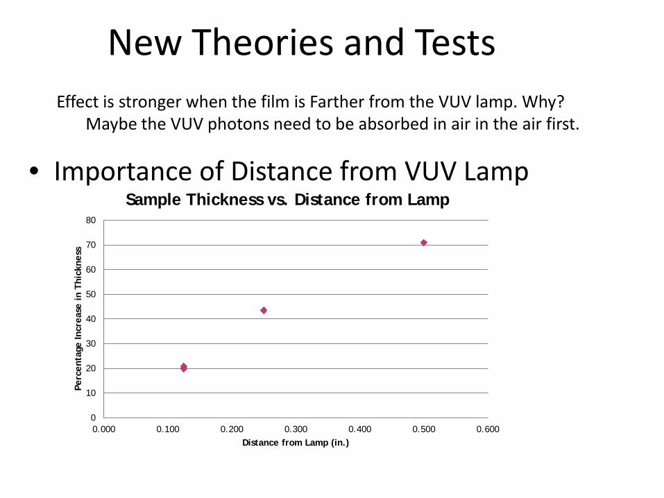
New Theories and Tests
• Importance of Distance from VUV Lamp
0
10
20
30
40
50
60
70
80
0.000 0.100 0.200 0.300 0.400 0.500 0.600
Perc
enta
ge In
crea
se i
n Th
ickn
ess
Distance from Lamp (in.)
Sample Thickness vs. Distance from Lamp
Effect is stronger when the film is Farther from the VUV lamp. Why? Maybe the VUV photons need to be absorbed in air in the air first.

What do 7.27 eV photons do? They will produce atomic oxygen in air, which can also produce ozone. These are the species that are thought to remove contamination. Could O or O3 be making some new compound which is much thicker than the original oxide?
Ozonides are known for alkali metals & recently reported for some alkali earth metals. Could they occur for group III metals? That is Y(O3)3 . It would have 6 times as much O as Y2O3. Still, that is a lot of expansion!

New Theories and Tests (Cont.)
• Formation of an Ozonide
0 20 40 60 80
100 120 140 160 180 200
Control, atmosphere
97% Nitrogen gas
Thic
knes
s in
nm
Film Growth in Nitrogen Purge
before after
Oxygen is needed to make an ozonides. What if there is no oxygen in the atmosphere when the lamp is on? We expected no expansion.

New theories and Tests (cont.)
• Water Expansion During Lamp Exposure
0 10 20 30 40 50 60 70 80 90
100
Before After
Thic
knes
s in
nm
Annealed Sample in Nitrogen Purge
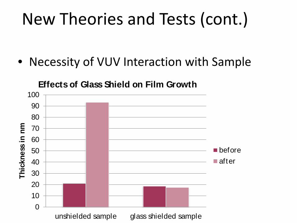
New Theories and Tests (cont.)
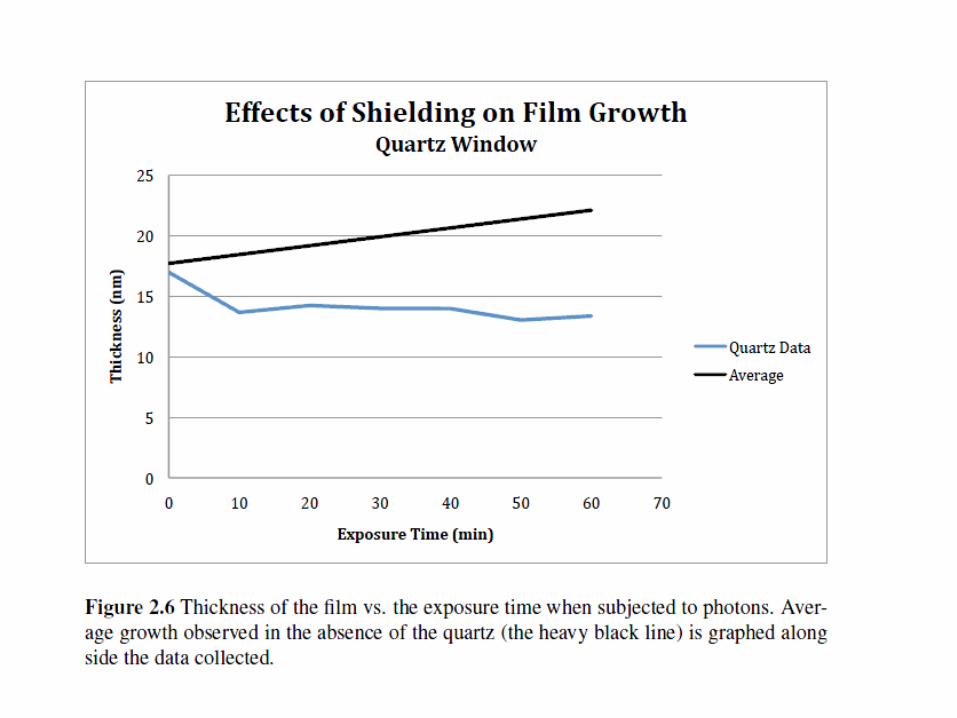
• Necessity of VUV Interaction with Sample
0
10
20
30
40
50
60
70
80
90
100
unshielded sample glass shielded sample
Thic
knes
s in
nm
Effects of Glass Shield on Film Growth
before after
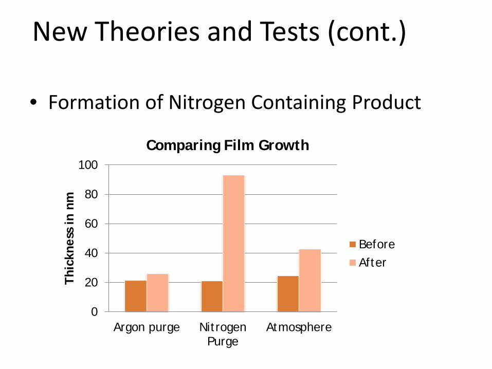
New Theories and Tests (cont.)
• Formation of Nitrogen Containing Product
0
20
40
60
80
100
Argon purge Nitrogen Purge
Atmosphere
Thic
knes
s in
nm
Comparing Film Growth
Before After
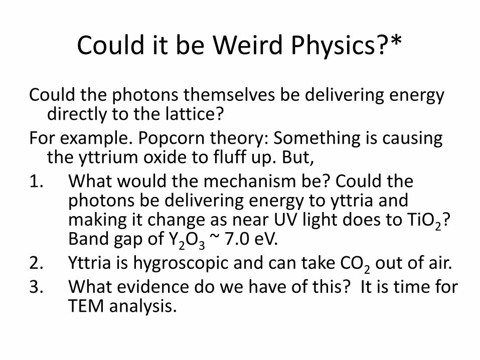
Could it be Weird Physics?*
Could the photons themselves be delivering energy directly to the lattice?
For example. Popcorn theory: Something is causing the yttrium oxide to fluff up. But,
1. What would the mechanism be? Could the photons be delivering energy to yttria and making it change as near UV light does to TiO2? Band gap of Y2O3 ~ 7.0 eV.
2. Yttria is hygroscopic and can take CO2 out of air. 3. What evidence do we have of this? It is time for
TEM analysis.


Further Theories and tests
• Use TEM (Transmission Electron Microscope) to characterize new material being formed – Figure out how to transfer the new
material onto the delicate TEM grid • Sputtering destroys grids • VUV process destroys grids
Take home message: Films expand from about 20 nm to almost 200nm and we still don’t know why.
Unprecedented!
We have looked at a lot of mechanisms. Yttria is thermodynamically very stable. If a VUV lamp can do this maybe the behavior of hafnia (now being used in the gate oxide of silicon devices) should be examined. Help us figure this out. What mechanism do you suggest and what experiments should we use to sort this out?


