Title pageMULTILIN B95 Plus BUS GE Digital Energy GE Multilin's Quality Management System is registered to ISO 9001:2008 QMI # 005094 UL # e83849 Instruction manual B95 Plus firmware revision: 1.00 GE publication code: GEK-113657 GE Digital Energy 650 Markland Street Markham, Ontario Canada L6C 0M1 Tel: +1 905 927 7070 Fax: +1 905 927 5098 Internet: http://www.GEDigitalEnergy.com *1601-0015-A2* LISTED 52TL IND.CONT. EQ. E83849 Multilin B95 Plus Bus Protection System
Multilin B95Plus Bus Protection System Instruction Manual for product revision 1.00.
Multilin B95Plus Bus Protection System, EnerVista, FlexLogic, FlexAnalog, Digital Energy, Multilin, and GE Multilin are trademarks or registered trademarks of GE Multilin Inc.
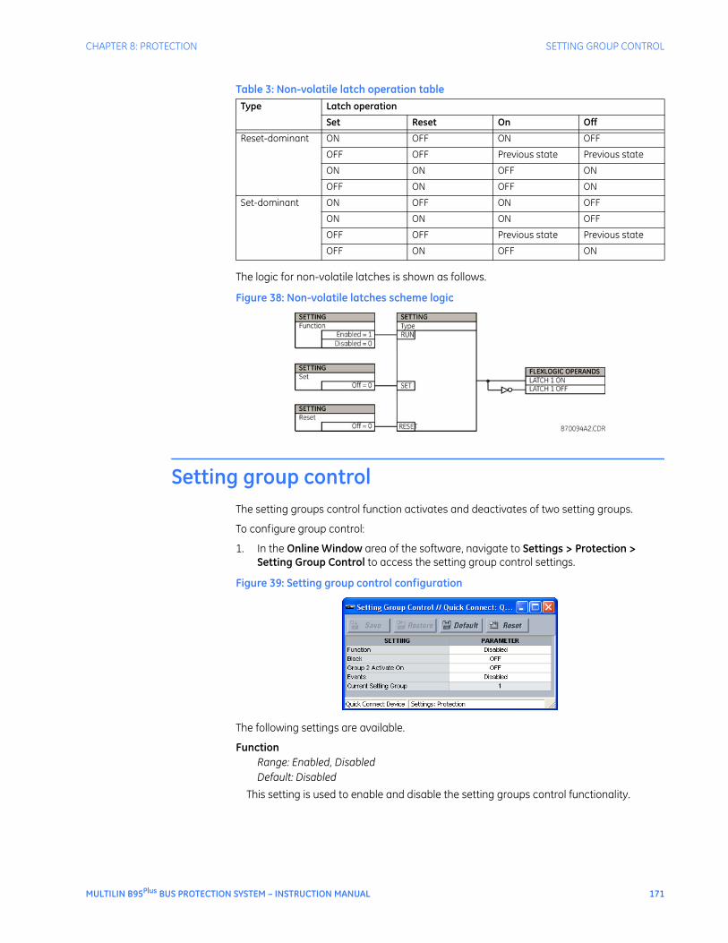
The contents of this manual are the property of GE Multilin Inc. This documentation is furnished on license and may not be reproduced in whole or in part without the permission of GE Multilin. The manual is for informational use only and is subject to change without notice.
Part number: 1601-0015-A2 (August 2012)
INSTRUCTION MANUAL
GENERAL SAFETY PRECAUTIONS - B95Plus
• The use of Omega-level safety shoes, safety gloves, safety glasses, and protective clothing are recommended during equipment installation, maintenance, and service.
• Failure to observe and follow the instructions provided in the instruction manual can cause damage to the equipment and can lead to property damage, personal injury, and/or death.
• Before attempting to use the equipment, review all danger and caution indicators.
• If the equipment is used in a manner not specified by the manufacturer or functions abnormally, proceed with caution. Otherwise, the protection provided by the equipment can be impaired and can result in damage and/or injury.
• Hazardous voltages can cause shock, burns, or death.
• Installation/service personnel must be familiar with general device test practices and electrical awareness. Safety precautions must be followed.
• Before performing visual inspections, tests, or periodic maintenance on this device or associated circuits, isolate or disconnect all live circuits and sources of electric power.
• Failure to power equipment off prior to removing the power connections can lead to exposure to dangerous voltages causing injury or death.
• All recommended equipment that can be grounded should be and must have a reliable and uncompromised grounding path for safety purposes, protection against electromagnetic interference, and proper device operation.
• Equipment grounds should be bonded together and connected to the facility’s main ground system for primary power.
• Keep all ground leads as short as possible.
• The equipment ground terminal must be grounded at all times during device operation and service.
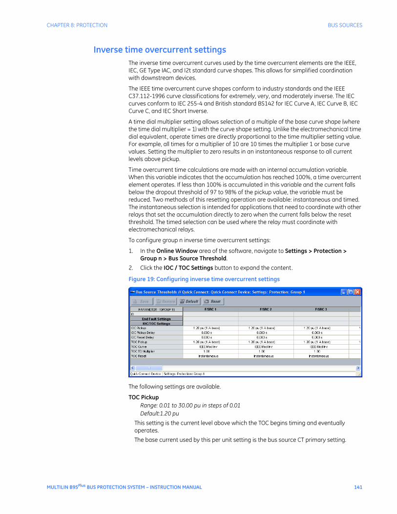
• In addition to the safety precautions mentioned, all electrical connections made must respect the applicable local jurisdiction electrical code.
• LED transmitters are classified as IEC 60825-1 Accessible Emission Limit (AEL) Class 1M. Class 1M devices are considered safe to the unaided eye. Do not view directly with optical instruments.
• Before working on current transformers (CTs), short-circuit them.
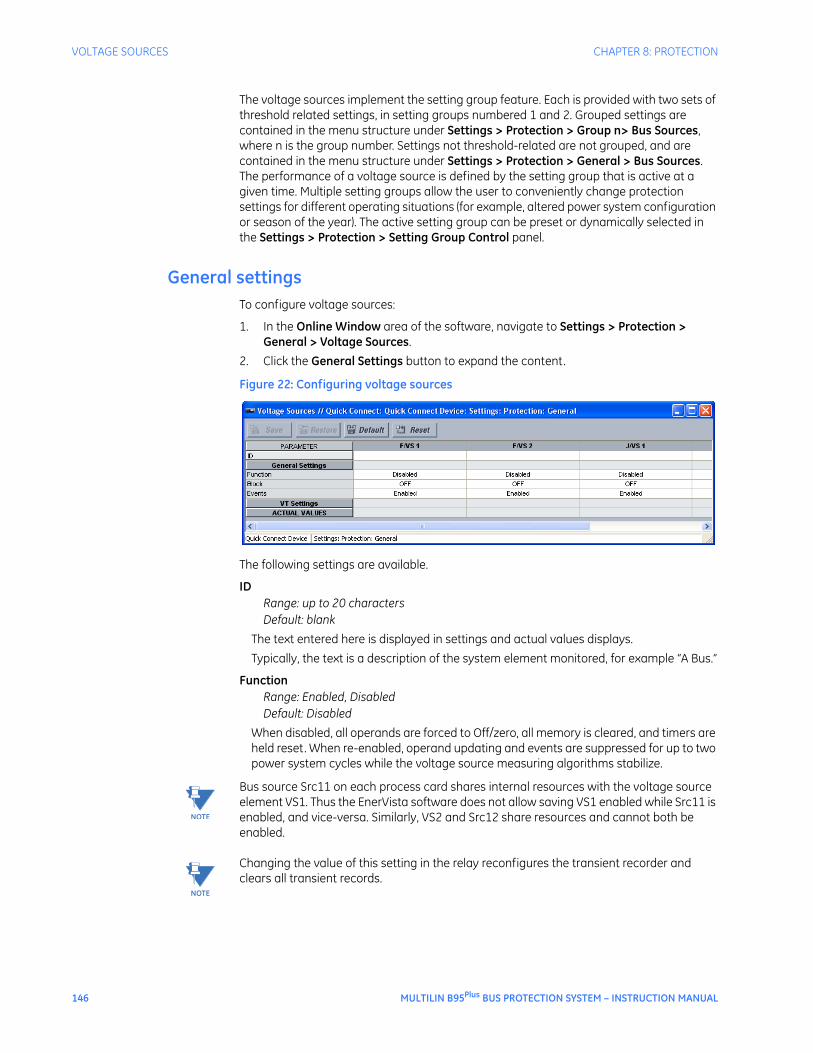
FCC/Industry Canada
This device complies with Part 15 of the FCC Rules and Industry Canada rules. Operation is subject to the following two conditions: (1) this device may not cause harmful interference, and (2) this device must accept any interference received, including interference that may cause undesired operation.
L’appareil conforme aux CNR d'Industrie Canada applicable aux appareils radio exempts de licence. L'exploitation est autorisé aux deux conditions suivantes: (1) l'appareil ne doit pas produire de brouillage, et (2) l'utilisateur de l'appareil doit accepter tout brouillage radiolectrique subi, même si le brouillage est susceptible d'en compromettre le fonctionnement.
Multilin B95Plus Bus Protection System
Table of contents
GETTING STARTED Safety words and definitions........................................................................................1Unpacking and inspection checklist ...........................................................................1Quick start .......................................................................................................................2For further assistance ...................................................................................................2
INSTALLATION Installing the unit in a rack.........................................................................................17Rear terminal and port layout ...................................................................................18Typical wiring diagram................................................................................................19Power supply card (slot A)...........................................................................................21Communications card (slot C) ....................................................................................22Main processor card (slot D).......................................................................................23
Ethernet port ................................................................................................................................................... 23IRIG-B port ........................................................................................................................................................ 24
Process cards (slot J and optionally slot F)..............................................................24
MULTILIN B95Plus BUS PROTECTION SYSTEM – INSTRUCTION MANUAL v
TABLE OF CONTENTS
ENERVISTA SOFTWARE
Introduction...................................................................................................................27Installing the EnerVista software ..............................................................................28Establishing communication via USB .......................................................................28Establishing communication via Ethernet...............................................................31Adding sites and devices.............................................................................................32Connecting to a device................................................................................................33Accessing settings........................................................................................................33
Operand quick select ...................................................................................................................................34Navigating long lists .....................................................................................................................................35Expanding/collapsing table rows...........................................................................................................35
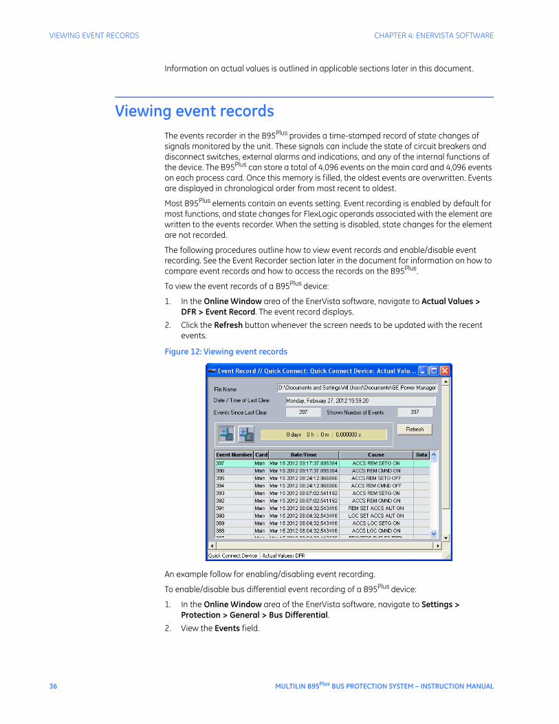
Viewing actual values..................................................................................................35Viewing event records .................................................................................................36Viewing transient records...........................................................................................37Settings files ..................................................................................................................37Deploying settings files to multiple devices using settings templates ..............38
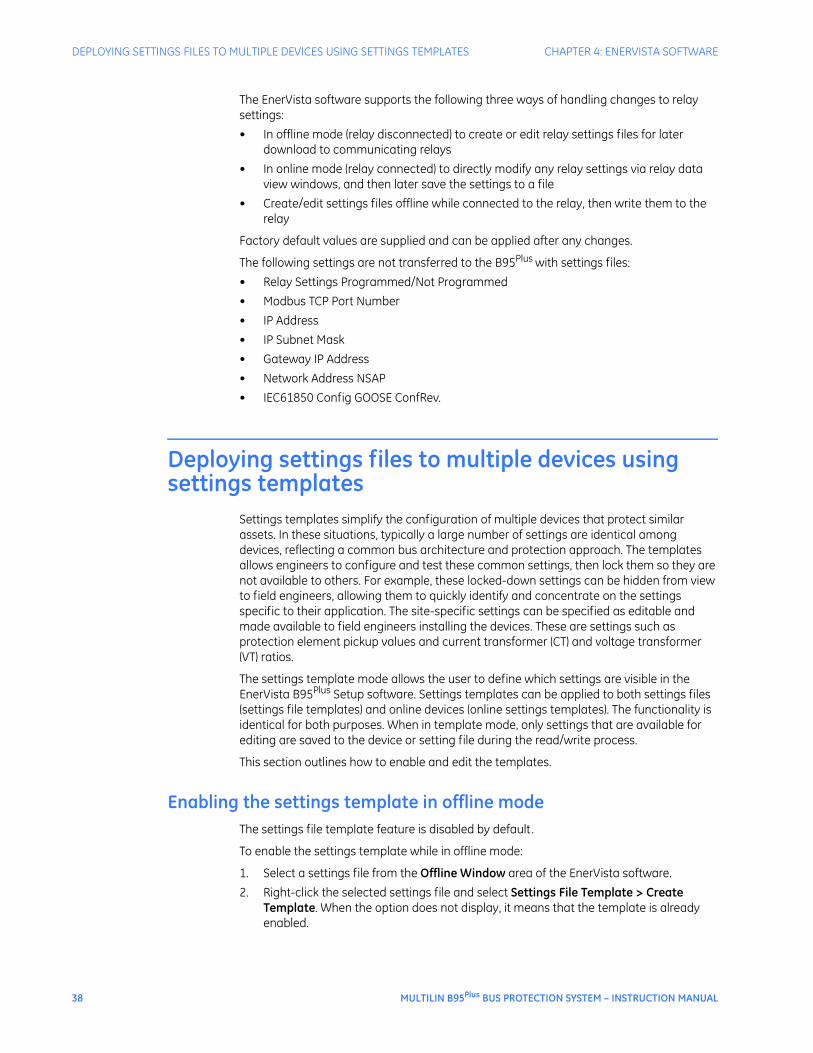
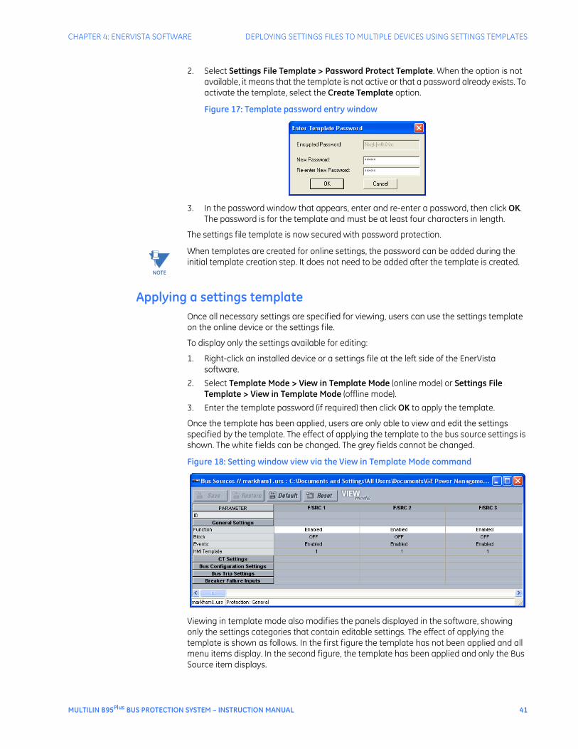
Enabling the settings template in offline mode...............................................................................38Enabling the settings template in online mode...............................................................................39Editing a settings template .......................................................................................................................40Adding password protection to a settings template ....................................................................40Applying a settings template....................................................................................................................41Removing a settings template.................................................................................................................42
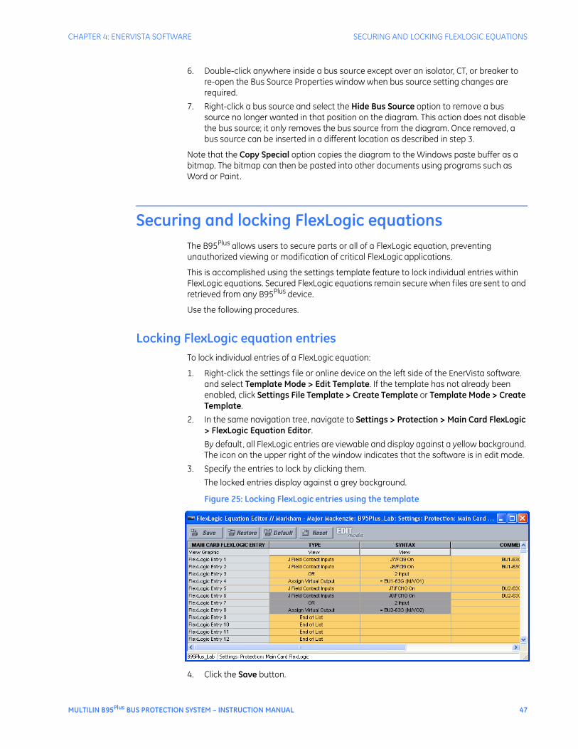
Bus replica graphical editor .......................................................................................42Securing and locking FlexLogic equations...............................................................47
Locking FlexLogic equation entries .......................................................................................................47Locking a settings file and FlexLogic equations to a serial number......................................48
DNP communications ..................................................................................................69Protocol...............................................................................................................................................................69User point list ...................................................................................................................................................72
vi MULTILIN B95Plus BUS PROTECTION SYSTEM – INSTRUCTION MANUAL
TABLE OF CONTENTS
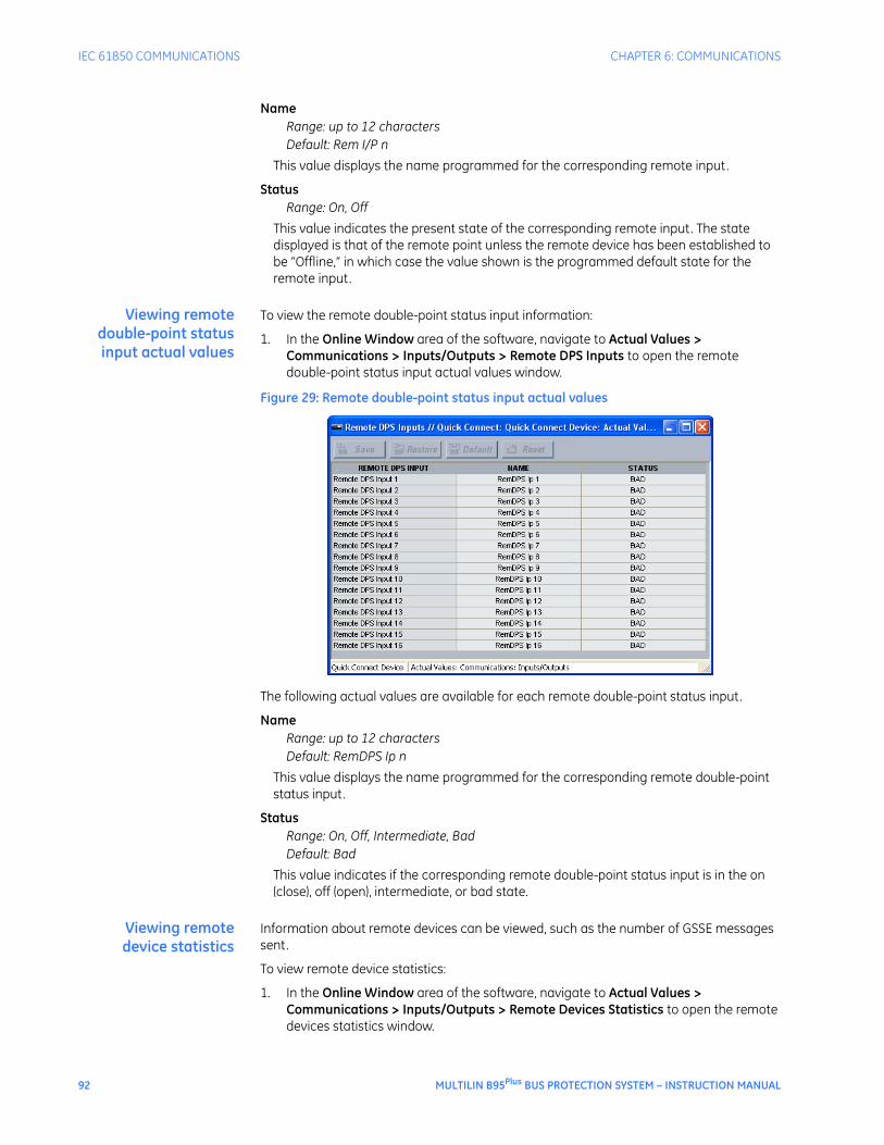
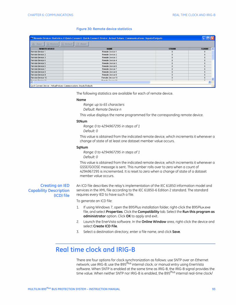
GGIO1 status configuration...................................................................................................................... 89Viewing IEC 61850 actual values........................................................................................................... 90
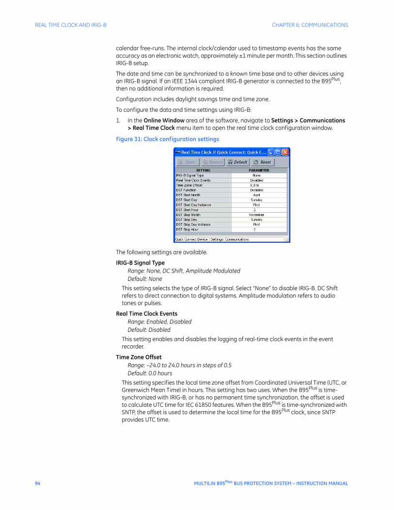
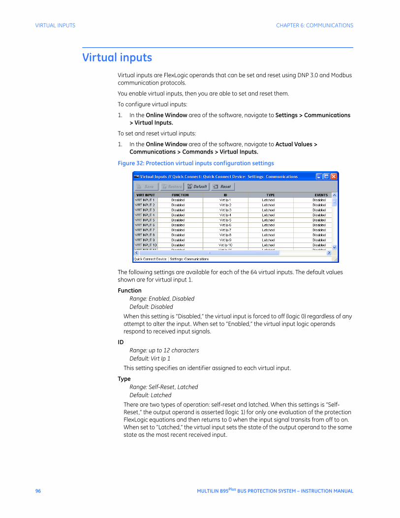
Real time clock and IRIG-B..........................................................................................93Virtual inputs.................................................................................................................96Communication logic operands ................................................................................97
MULTILIN B95Plus BUS PROTECTION SYSTEM – INSTRUCTION MANUAL vii
TABLE OF CONTENTS
Analog operands.........................................................................................................................................153Bus differential........................................................................................................... 153
General settings...........................................................................................................................................155Operating characteristic settings........................................................................................................157Supervision settings...................................................................................................................................160Actual values.................................................................................................................................................163FlexLogic operands....................................................................................................................................164Analog operands.........................................................................................................................................165
Bus replica graphical editor .................................................................................... 165FlexLogic ..................................................................................................................... 165
FlexLogic rules..............................................................................................................................................167FlexLogic gates and operators.............................................................................................................167FlexLogic equation editor........................................................................................................................168FlexLogic timers...........................................................................................................................................169Non-volatile latches...................................................................................................................................169
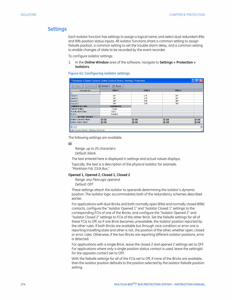
Setting group control................................................................................................ 171Isolators ...................................................................................................................... 172
SECURITY User and password management .......................................................................... 205Local and remote passwords .................................................................................. 206Access alarms ............................................................................................................ 209
viii MULTILIN B95Plus BUS PROTECTION SYSTEM – INSTRUCTION MANUAL
TABLE OF CONTENTS
PRODUCT INFORMATION
Serial number............................................................................................................. 213
MAINTENANCE Test mode ................................................................................................................... 215Self-tests ..................................................................................................................... 216
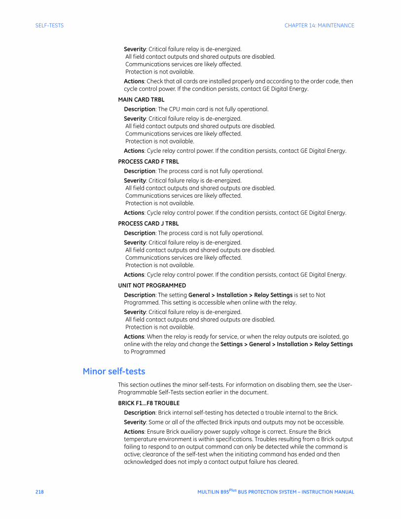
Major self-tests............................................................................................................................................ 217Minor self-tests............................................................................................................................................ 218FlexLogic operands ................................................................................................................................... 220
Set date and time ...................................................................................................... 221Raw data viewer ........................................................................................................ 222
Analog inputs ............................................................................................................................................... 223Contact and shared input/output ...................................................................................................... 224Diagnostics.................................................................................................................................................... 226
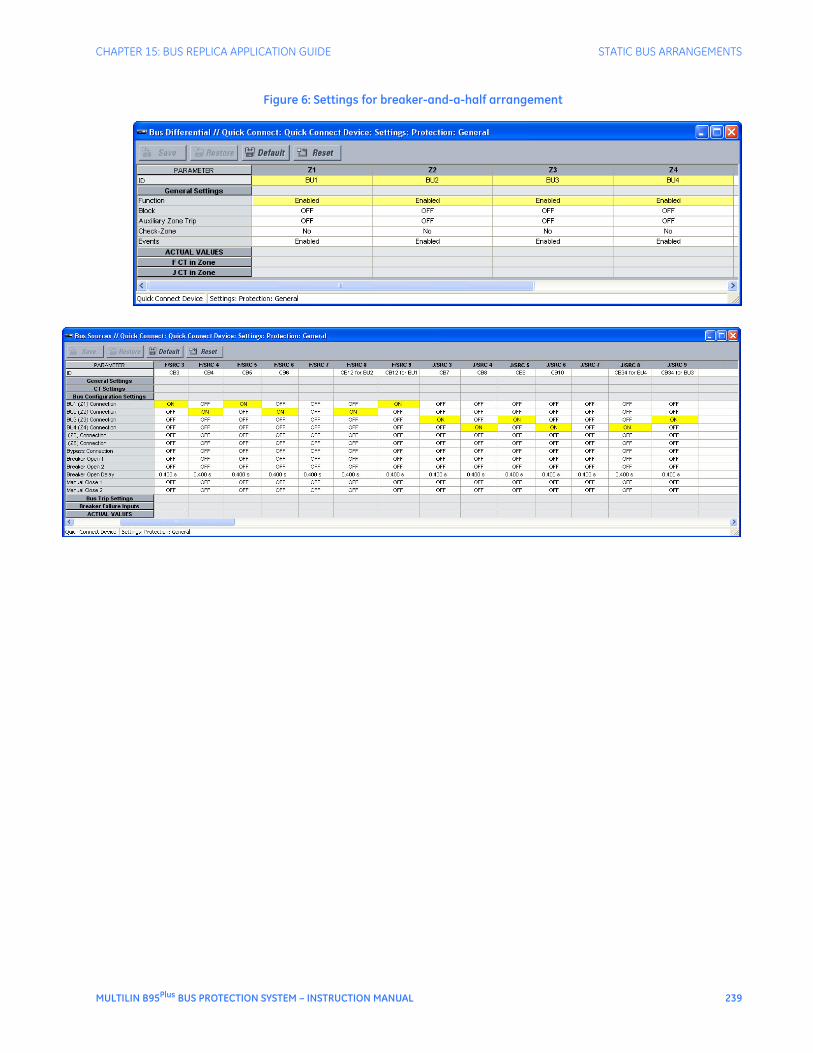
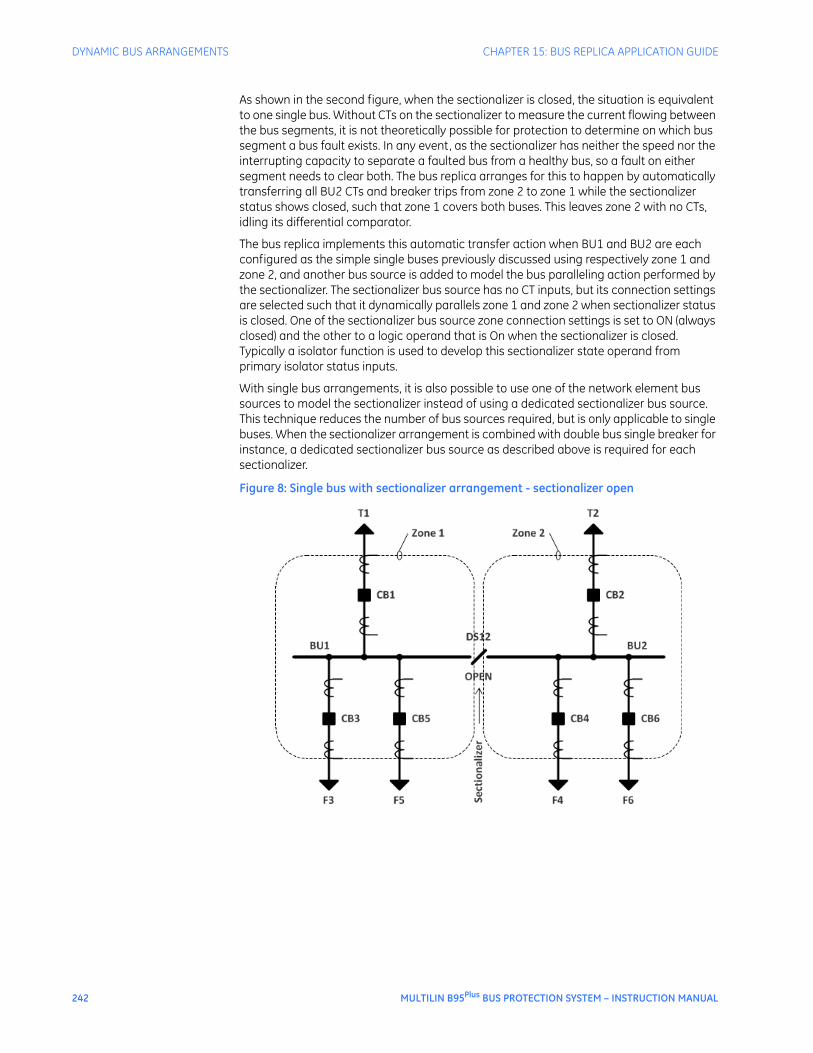
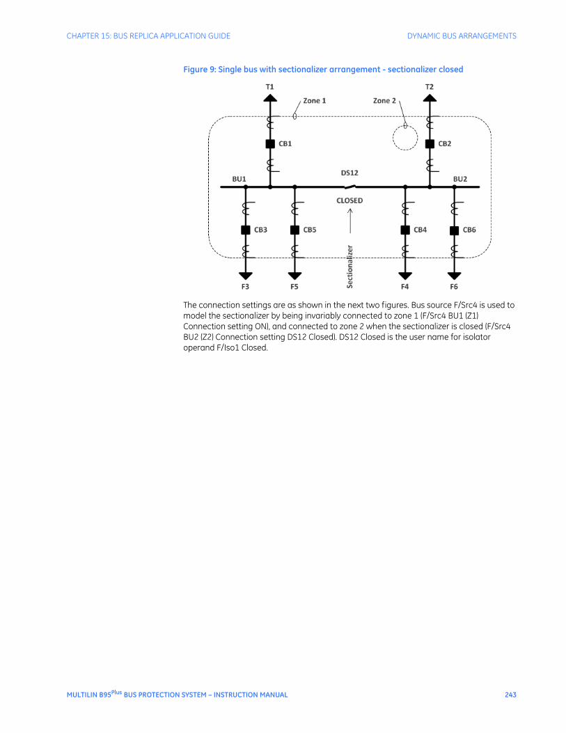
Static bus arrangements ......................................................................................... 233Dynamic bus arrangements.................................................................................... 241
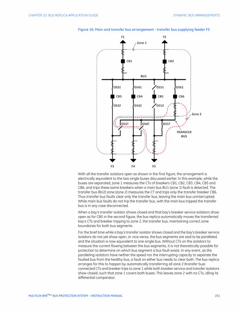
Sectionalized bus........................................................................................................................................ 241Double-bus single-breaker .................................................................................................................... 246Main and transfer bus.............................................................................................................................. 250Breaker bypass switches ........................................................................................................................ 255
Check zones................................................................................................................ 256Undervoltage supervision........................................................................................ 260Zone expansion/reduction and end fault protection ......................................... 260Breaker failure ........................................................................................................... 261
APPENDIX Revision history ......................................................................................................... 263Warranty..................................................................................................................... 263
MULTILIN B95Plus BUS PROTECTION SYSTEM – INSTRUCTION MANUAL ix
TABLE OF CONTENTS
x MULTILIN B95Plus BUS PROTECTION SYSTEM – INSTRUCTION MANUAL
Multilin B95Plus Bus Protection System
Chapter 1: Getting started
Getting started
This section outlines the symbols used in the document, what is in the box, and general approach to set up the Multilin B95Plus Bus Protection SystemTM.
Safety words and definitionsBefore attempting to install or use the device, review all safety indicators in this document to help prevent injury, equipment damage, or downtime.
The following safety and equipment symbols are used in this document.DANGER: Indicates a hazardous situation which, if not avoided, will result in death or serious
injury.IMPORTANT: Indicates a hazardous situation which, if not avoided, could result in death or serious
injury.CAUTION: Indicates a hazardous situation which, if not avoided, could result in minor or
moderate injury.FASTPATH: Indicates practices not related to personal injury.
Unpacking and inspection checklistUse this procedure to unpack and inspect the B95Plus.
1. Inspect the packaging for physical damage.
2. Open it and inspect the B95Plus for physical damage.
3. Check that the following items have been delivered:
– Multilin B95Plus Bus Protection System
– GE EnerVistaTM CD (software and documentation)
– Instruction Manual (if ordered)
– Certificate of Calibration
MULTILIN B95Plus BUS PROTECTION SYSTEM – INSTRUCTION MANUAL 1
QUICK START CHAPTER 1: GETTING STARTED
– Test Report
– EC Declaration of Conformity
4. View the rear nameplate of the product and verify that the correct model has been delivered.
5. For product information, instruction manual updates, and software updates, visit the GE Multilin website at http://gedigitalenergy.com/multilin.
6. If any of the contents listed are missing or there is physical damage to the product, contact GE Digital Energy immediately using the contact information in the For Further Assistance section.
Quick startThe process for installing the unit is as follows:
• Install the unit in a rack (see Installing the Unit in a Rack)
• Connect the power supply and wire the unit (see Typical Wiring Diagram)
• Install the EnerVista software on a computer (see Installing the EnerVista Software)
• Connect the computer to the unit using a USB or Ethernet cable. Use of a USB cable is recommended for setup because of ease of use, after which you can switch to Ethernet for faster communications. (See Establishing Communication via USB and see Establishing Communication via Ethernet. Setup using the USB cable is documented.)
• Configure the unit by accessing the Settings panels in the Online Window area of the EnerVista software. Use this document for information as you work through the settings panels.
• Configure user access (see Security)
If a device is not available, one can still familiarize oneself by installing EnerVista software and experimenting with the Offline Window features, skipping the steps involving a device.
Note that the chapters starting with Settings - General largely follow the structure displayed in the software.
For further assistanceFor product support, contact the information and call center as follows:
Comments about new features or modifications for specific requirements are welcome.
2 MULTILIN B95Plus BUS PROTECTION SYSTEM – INSTRUCTION MANUAL
Multilin B95Plus Bus Protection System
Chapter 2: Product description
Product description
This chapter provides an overview and technical specifications of the Multilin B95Plus Bus Protection System.
Device overviewThe Multilin B95Plus Bus Protection System is a relay to detect faults on a bus. It measures currents connected to the bus and when it detects a fault on the bus, it sends signals to isolate the bus. When there is a fault on a bus, the entire bus goes down, making the B95Plus crucial. The B95Plus extends the URPlus-series product family and the HardFiberTM Process Bus product family to provide a distributed, low impedance, current differential protection solution for medium and high voltage large and reconfigurable buses.
Figure 1: Front view
MULTILIN B95Plus BUS PROTECTION SYSTEM – INSTRUCTION MANUAL 3
DEVICE OVERVIEW CHAPTER 2: PRODUCT DESCRIPTION
The protection system consists of a distributed process interface (data acquisition and tripping) architecture using GE HardFiber Bricks, with centralized processing performed by the B95Plus.
The functions of the B95Plus include the following:
• Multi-zone differential protection with both restrained (dual-slope percent or biased) and unrestrained (unbiased or instantaneous) functions incorporated. Differential protection is fast and secure. Security is achieved by using a reliable current transformer (CT) saturation detection algorithm and a directional comparison operating principle. Security is further enhanced by support for redundant process interface (Bricks). Three-phase tripping is supported; differential protection operands are provided for individual phase tripping.
• Interfaces with up to eight HardFiber Bricks per process card. The B95Plus can contain one or two process cards.
• Supports up to 12 bus sources per process card. A single bus source is used to interface a network element connection to the bus, such as a feeder, line, transformer, capacitor, or reactor. A single bus source is used to interface a bus tie disconnect. Two bus sources are used to interface a bus tie breaker.
• Dynamic bus replica functionality and multi-zone protection is supported allowing application of the B95Plus to multi-section reconfigurable buses. A zone expansion/contraction to an open breaker feature is included.
• Check-zone functionality can be configured by programming one of the differential zones to enclose the entire bus.
• Supports up to two undervoltage functions per process card for differential protection supervision purposes.
• End-fault protection (dead-zone protection) is provided for each bus source.
• A breaker fail function with three-phase tripping support and fast resetting current detectors is provided for each bus source.
• An instantaneous phase overcurrent function is provided for each bus source for possible supervision purposes.
• An inverse time phase overcurrent function is provided for each bus source for possible backup protection.
• An isolator position resolution and monitoring feature monitors 48 isolators per process card.
• A CT trouble monitoring function is provided for each zone of differential protection.
Voltage and current metering are built into the relay as standard features, as fundamental frequency-only root mean square (RMS) scaled magnitude and angle (phasor).
Diagnostic features include an event recorder capable of storing 4,096 time-stamped events plus 4,096 time-stamped events per process card. Oscillography is user-programmable as to sampling rate (up to 128 samples per cycle), content, writing mode, and record length. The internal clock used for time stamping can be synchronized with an IRIG-B signal or using the simple network time protocol (SNTP) over Ethernet. This precise time stamping allows the sequence of events to be determined throughout the system. Events can also be programmed using FlexLogicTM equations to trigger oscillography data capture, which can be set to record the measured parameters before and after the event for viewing on a computer. These tools significantly reduce troubleshooting time and simplify report generation in the event of a system fault.
On the communications card, either of the two Ethernet ports can be used for supervisory control and data acquisition (SCADA) access, the programming of settings, and the monitoring of actual values. These two Ethernet ports have both 100Base-TX and
4 MULTILIN B95Plus BUS PROTECTION SYSTEM – INSTRUCTION MANUAL
CHAPTER 2: PRODUCT DESCRIPTION DEVICE OVERVIEW
100Base-FX interfaces, and they can be used to provide fast, reliable communications in noisy environments. These ports support TFTP, SNTP, IEC 61850, Modbus/TCP, and IEC 60870 protocols. DNP 3.0 and IEC 60870 cannot be enabled at the same time.
A third Ethernet port supports engineering access using the EnerVista B95Plus SetupTM software.
The B95Plus intelligent electronic devices (IEDs) use Flash memory technology that allows field upgrading as new features are added.
The following single-line diagram illustrates the relay functionality using American National Standards Institute (ANSI) device numbers.
Table 1: ANSI device numbers and functions
Figure 2: ANSI device number schematic
Device Function
87B Percent bus differential
27 Undervoltage
50 Instantaneous overcurrent
50/74 CT trouble
50/87 Unrestrained bus differential
50EF End fault protection
51 Time overcurrent
50BF Breaker failure
MULTILIN B95Plus BUS PROTECTION SYSTEM – INSTRUCTION MANUAL 5
HARDFIBER OVERVIEW CHAPTER 2: PRODUCT DESCRIPTION
Table 2: Other device functions
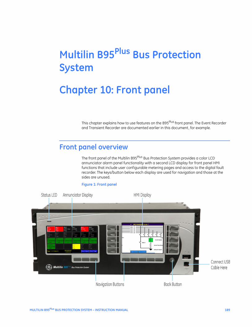
Advanced functionality allows the user to access comprehensive information without having to navigate through conventional displays and keypads. Information displays on two graphical display panels on the front panel. One serves as a digital annunciator and the other, called the HMI, displays mimic diagrams, phasor plots, and other information.
The configurable, color LCD annunciator on the front panel eliminates the need for LEDs and separate annunciator devices. Any contact input, remote input, or internally generated logic operand can be assigned to each indicator, as well as any analog operand. Up to 288 indicators can be assigned. The display can be configured for 12, 24, or 48 indicators per page. A separate self-test message page on the annunciator panel displays error messages about device health.
The HMI panel provides easy access and visualization of device information, ranging from the graphical and numeric display of bus source current phasors, voltage source phasors, differential and restraint phasors, and tracking frequency, as well as a display of sequence of events and a transient records list. The HMI can display a mimic diagram that provides the status of each bus source’s breaker and isolators. Many bay configurations can be realized through the setting of the device.
FlexLogic equationsFlexLogic refers to executable code developed by GE or you for use with the device. You can create or edit FlexLogic equations in order to customize the relay’s behavior. You can subsequently view automatically generated logic diagrams.
HardFiber overviewThe GE HardFiber Process Bus System allows copper wiring to be replaced in substation switchyards with optical fiber. The system includes all physical components required for its installation: relays; factory pre-terminated fiber cables; fiber crossconnect panels; factory connectorized copper cables; and switchyard I/O interface devices known as Bricks. The Bricks implement the concept of an IEC 61850 merging unit, expanded to optically connect relays with all types of input and output signals in the switchyard, not just instrument transformers. The relays are the proven GE Multilin Universal Relay (UR) series devices with a decade-long field record, and they incorporate all major applications from a simple
Function Function
HardFiber Brick interface (8 Bricks per process card)
Differential zone expansion/contraction
Field contact inputs (144 per process card) Event recorder
Field contact outputs (48 per process card) Transient recorder (oscillography)
Current AC banks (12 per process card) Voltage AC banks (2 per process card)
Time synchronization via SNTP or IRIG-B
Dynamic bus replica User-definable mimic, metering, and annunciator displays
End-fault protection User-programmable self-test
DNP 3.0 or IEC 60870-5-104 communications Virtual inputs (64)
IEC 61850 communications, including GOOSE and sampled values
Virtual outputs (96 plus 96 per process card)
Metering: current, voltage, tracking frequency FlexLogic equations (512 lines plus 512 lines per process card of protection speed code)
Modbus communications Non-volatile latches (16 plus 16 per process card)
Modbus user map Setting groups (2)
6 MULTILIN B95Plus BUS PROTECTION SYSTEM – INSTRUCTION MANUAL
CHAPTER 2: PRODUCT DESCRIPTION HARDFIBER OVERVIEW
feeder relay to a sophisticated generator protection package. With the release of the B95Plus, the HardFiber system can also be used for the protection of large and dynamic buses.
Figure 3: GE HardFiber Brick top view
The HardFiber system replaces copper wiring between power apparatus in the switchyard and protection and control devices in the control house with off-the-shelf components that use standard physical and logical interfaces. As such, it shortens deployment time, reduces labour requirements, facilitates work transfer, improves quality, simplifies procurement, and improves safety.
Figure 4: B95Plus in control house and HardFiber Bricks in switchyard
Bricks, cables, and crossconnect panels can simultaneously connect to the B95Plus relays and UR-series relays. For example, a Brick located in a feeder bay can be used by a D60 Line Distance Protection System protecting the feeder and a B95Plus protecting the bus.
The B95Plus is designed to work with GE HardFiber Bricks. Any references to Bricks in this manual refer to HardFiber Bricks.
MULTILIN B95Plus BUS PROTECTION SYSTEM – INSTRUCTION MANUAL 7
ORDER CODES CHAPTER 2: PRODUCT DESCRIPTION
Details of the HardFiber Bricks, cables, crossconnect panels, and protocols are contained in the HardFiber Process Bus System Reference Manual. Chapters 5 and 6 of the HardFiber manual do not apply to the B95Plus because the B95Plus has its own process card, settings, actual values, and self-test errors.
Order codesThe B95Plus is a 19-inch horizontal rack-mount unit that consists of required and optional cards. For the B95Plus, only process card F is optional.
Reading across the order code table, an example of an ordering code is B95P-HE-BX03SSX-XHXAXPXXPX.
NOTE
NOTE: Order codes are subject to change without notice. See the GE Multilin ordering page at http://store.gedigitalenergy.com/Multilin/front.asp for the latest B95Plus options.
For communications, the DNP option or the IEC 60870-5-104 option is ordered, not both.
Figure 5: Order codes
After the unit is set up, the order code is viewable in the EnerVista software.
To view the order code:
1. In the Online Window area of the EnerVista software, navigate to Actual Values > Product Information > Model Information. Or view the code on the Product Information page on the front panel annunciator display.
SpecificationsThis section outlines specifications, which are subject to change without notice.
8 MULTILIN B95Plus BUS PROTECTION SYSTEM – INSTRUCTION MANUAL
CHAPTER 2: PRODUCT DESCRIPTION SPECIFICATIONS
Remote resources specificationsREMOTE RESOURCE SPECIFICATIONSNumber of field units (bricks): .......................8 per process cardNumber of field contact inputs: ...................18 for each brickNumber of field contact outputs:................6 for each brickNumber of field latching outputs:...............1 for each brickNumber of shared inputs: ...............................16 per process cardNumber of shared outputs:............................16 per process card
Protection specificationsBUS DIFFERENTIAL PROTECTIONComparator algorithm: ....................................low impedance differential with through current restraint,
direction and CT saturation supervision (same as B90)Number of differential zones: .......................six 3-phase zonesMaximum number of currents: ....................total dynamic number of bus source to zone connections
closed at any one moment in time up to 120CT ratio compensation range: ......................32:1Supervision: ...........................................................2 user-programmable conditions per zonePickup level: ...........................................................0.050 to 2.000 pu on bus base in steps of 0.001 puLow slope:...............................................................15 to 100% in steps of 1%High slope: .............................................................50 to 100% in steps of 1%Low breakpoint: ...................................................1.00 to 30.00 pu on bus base in steps of 0.01 puHigh breakpoint:..................................................1.00 to 30.00 pu on bus base in steps of 0.01 puDropout level:........................................................<98% of pickupLevel accuracy: .................................................... 0.1 to 2.0 × bus base: .......................................±0.5% of reading or ±1% of bus base (whichever is greater) >2.0 × bus base: .................................................±1.5% of readingOperating time: ....................................................<1 power system cycleHigh set (unbiased) level:.................................2.00 to 99.99 pu in steps of 0.01 puHigh set (unbiased) operate time: ...............<1 power system cycle
CT TROUBLE MONITORINGNumber of CT trouble detectors:.................1 per bus differential zone, that is, 6Responding to: .....................................................differential currentPickup level: ...........................................................0.020 to 2.000 pu in steps of 0.001 puCT trouble operate delay:................................1.0 to 60.0 s in steps of 0.1 sSupervision trouble delay: ..............................0.00 to 5.00 cycles in steps of 0.25
BUS REPLICAFeatures: .................................................................Dynamic bus source current assignment to each zone.
Dynamic zone trip assignment to each bus source. Dynamic blocking of zones on CT bypassed. 3 user-programmable auxiliary zone trip inputs. 3 user-programmable bus source trip inputs. Dynamic zone expansion/reduction.
BUS SOURCESNumber of bus sources:...................................12 per process card included in the order codeCurrent inputs:......................................................3-phase currentsCT rated primary: ................................................1 to 65000 ACT rated secondary: ..........................................1 or 5 ANominal frequency: ...........................................50 or 60 Hz
MULTILIN B95Plus BUS PROTECTION SYSTEM – INSTRUCTION MANUAL 9
SPECIFICATIONS CHAPTER 2: PRODUCT DESCRIPTION
BREAKER FAILURE PROTECTIONNumber of BF protections: .............................1 per bus sourceMode:........................................................................3-pole initiate onlyCurrent supervision: ..........................................phase currentCurrent supervision pickup:...........................0.01 to 30.00 pu on CT base in steps of 0.01 puCurrent supervision dropout: ........................<98% of pickupCurrent supervision accuracy: ..................... 0.1 to 2.0 × CT rating:.......................................±0.75% of reading or ±2% of CT base (whichever is greater) above 2 × CT rating: .........................................±2.5% of readingCurrent supervision reset time:....................< 0.5 cyclesCoordination delay timers:.............................0 to 60 s in steps of 1 msDelay accuracy:...................................................±3% or ±4 ms, whichever is greaterBreaker position inputs:...................................advanced and final position contact inputs, each optionally
dual-redundantStages: ..................................................................... current + advanced breaker position status + time
current + timefinal breaker position + timeopening resistor protection
INSTANTANEOUS PHASE OVERCURRENTNumber of IOC protections:...........................1 per bus sourceComparators: .......................................................3 phase, sensing fundamental frequency currentPickup level:...........................................................0.00 to 30.00 pu on CT base in steps of 0.01Dropout level: .......................................................<98% of pickupLevel accuracy:.................................................... 0.1 to 2.0 × CT:.....................................................0.5% of reading or 1% of CT base (whichever is greater) above 2.0 × CT: ...................................................1.5% of readingPickup delay:.........................................................0 to 60 s in steps of 1msReset delay: ...........................................................0 to 60 s in steps of 1msDelay accuracy:...................................................±3% or ±4 ms (whichever is greater)Operate time:........................................................<1 power system cycle at 3 x pickup
INVERSE TIME PHASE OVERCURRENTNumber of TOC protections:..........................1 per bus sourceComparators: .......................................................3 phase, sensing fundamental frequency currentPickup level:...........................................................0.01 to 30.00 pu on CT base in steps of 0.01 puDropout level: .......................................................<98% of pickupLevel accuracy:.................................................... 0.1 to 2.0 × CT:.....................................................0.5% of reading or 1% of CT base (whichever is greater) above 2.0 × CT: ...................................................1.5% of readingCurve shapes:....................................................... IEEE Moderately/Very/Extremely Inverse; IEC (and BS) A/B/C
and Short Inverse; GE IAC Inverse, Short/Very/ Extremely Inverse; I2t; Definite Time (0.01 s base curve)
TD multiplier:.........................................................0.00 to 600.00 in steps of 0.01Reset type: ............................................................. instantaneous or timed (per IEEE)Timing accuracy: ................................................±3% or ±40 ms (whichever is greater)
END FAULT PROTECTIONNumber of EFPs:..................................................1 per bus sourceIOC pickup level: ..................................................0.01 to 30.00 pu in steps of 0.01 puIOC dropout level: ...............................................<98% of pickupLevel accuracy:.................................................... at 0.1 to 2.0 × CT: ...............................................0.5% of reading or 1% of nominal (whichever is greater) above 2.0 × CT: ...................................................1.5% of readingCB open delay timer:.........................................0.10 to 60 s in steps of 1 msEnd fault dropout timer: ..................................0 to 60 s in steps of 1 msTime accuracy: ....................................................±3% or ±8 ms (whichever is greater)
10 MULTILIN B95Plus BUS PROTECTION SYSTEM – INSTRUCTION MANUAL
CHAPTER 2: PRODUCT DESCRIPTION SPECIFICATIONS
VOLTAGE SOURCESNumber of voltage sources: ..........................2 per process card included in the order codeVoltage inputs: .....................................................3-phase voltages, wye or deltaVT ratio:....................................................................1.00 to 24000.00VT rated secondary: ..........................................25.0 to 240.0 VNominal frequency: ...........................................50 or 60 Hz
UNDERVOLTAGE PROTECTIONNumber of UV protections:.............................2 per process cardComparators:........................................................3 phase-to-phase and 3 phase-to-groundPickup level: ...........................................................0.50 to 1.50 pu in steps of 0.01Dropout level:........................................................>102% of pickupLevel accuracy: ....................................................±0.5% of reading from 10 to 208 VOperate time:........................................................<1 power system cycle at 0.5 x pickup
ISOLATORSNumber of isolators:..........................................48 per process cardIsolator status inputs: .......................................form “a” and form “b” contact inputs, each optionally dual-
redundantConfigurable failsafe modes: ........................open, closed, last valid stateMonitoring:.............................................................alarm on inconsistent inputs persisting longer than a user
set time
FLEXLOGIC DESIGNProgramming language: ................................. Reverse Polish Notation with graphical visualizationInputs:....................................................................... Any logical variable, contact, or virtual inputNumber of timers:............................................... 32 per process card plus 32 on main cardTimer pickup delay:............................................ 0 to 1000 hrs in steps of 1 msTimer dropout delay:......................................... 0 to 1000 hrs in steps of 1 msTimer accuracy:................................................... ± the sum of 1/8 power system cycle and 1% of the timer
settingVirtual outputs: .................................................... 96 per process card plus 96 on main cardNon-volatile latch latches:.............................. 16 per process card plus 16 on main cardNon-volatile latch modes:............................... Set-dominant or reset-dominantLines of code:........................................................ 512 per process card plus 512 on main cardSupported operations: ..................................... NOT, XOR, OR (2 to 16 inputs), AND (2 to 16 inputs), NOR (2 to
Execution speed: ................................................. recalculated at 8 times per power system cycleCard-to-card operand delay: ........................ up to 1/8 power system cycle
SETTINGS GROUPSNumber of settings groups: ...........................2Grouped settings: ...............................................threshold type settings for bus source, voltage source, and
bus differential
Communications specificationsMODBUS USER MAPNumber: ..................................................................up to 256 Modbus addressesProgrammability: ................................................any setting or actual value in decimal
REMOTE INPUTS (IEC 61850 GSSE/GOOSE)Input points:...........................................................64Remote devices: ..................................................32Default states on loss of
communications:...........................................On, Off, Latest/Off, Latest/OnRemote double-point status inputs: ..........16
MULTILIN B95Plus BUS PROTECTION SYSTEM – INSTRUCTION MANUAL 11
SPECIFICATIONS CHAPTER 2: PRODUCT DESCRIPTION
REMOTE OUTPUTS (IEC 61850 GSSE/GOOSE)GSSE:.........................................................................32 DNA + 32 UserStGOOSE: ....................................................................128 status
IEC 61850 LOGICAL NODESLLNO: ........................................................................1 logical node zeroLPHD: ........................................................................1 physical device informationGGIO: ........................................................................GGIO1, general status outputPDIF: ..........................................................................6 differential zonesPIOC: .........................................................................1 per bus source instantaneous overcurrentPTOC: ........................................................................1 per bus source timed overcurrentPTUV: ........................................................................1 per undervoltageRBRF:.........................................................................1 per bus source breaker failurePTRC:.........................................................................1 per bus sourceMMXU:......................................................................1 per bus source phase current bankMMXU:......................................................................1 per voltage source
IEC 61850 REPORTSUnbuffered control blocks:.............................3 for GGIO1
3 for each PDIF3 for each MMXU
Buffered control blocks:...................................2 for GGIO11 for each PDIF1 for each MMXU
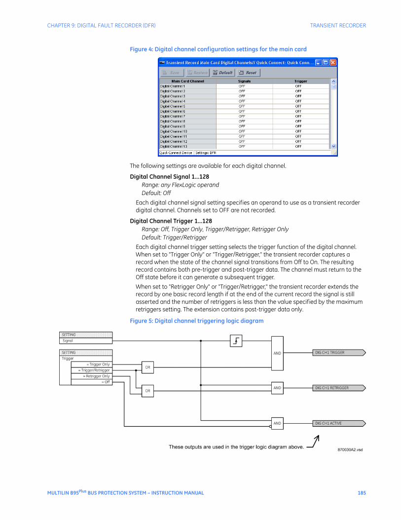
Digital fault recorder specificationsTRANSIENT RECORDERStorage capacity:................................................ five records with all channels recorded, at 128 samples per
cycle, spanning 1 second with no retriggersNumber of records:............................................up to 50Sampling rate:......................................................8, 16, 32, 64, or 128 samples per power cycleAC waveform channels:...................................all enabled bus sources and voltage sourcesAnalog channels: ................................................magnitudes and angles of all AC waveforms recorded plus
all enabled zone differential and zone restraint phase current magnitudes and angles
Digital channels:..................................................128 user-configurable channels on the main card and 128 user-configurable channels on each process card
Configurable digital data:...............................any FlexLogic operandStorage modes: ...................................................automatic overwrite, protectedTriggering modes: .............................................. time window from rising edge of trigger, continuous
recording as long as trigger is activePre-trigger window:...........................................0 to 100% of the basic record lengthData storage:........................................................non-volatile memory
EVENT RECORDERStorage capacity:................................................4,096 events plus 4,096 events on each process cardTime tag:................................................................. to 1 µsTriggers: ..................................................................most FlexLogic operand activations
12 MULTILIN B95Plus BUS PROTECTION SYSTEM – INSTRUCTION MANUAL
CHAPTER 2: PRODUCT DESCRIPTION SPECIFICATIONS
Front panel interfaceANNUNCIATOR MAIN DISPLAYAnnunciator pages: ...........................................Indicators: ..............................................................288 Indicators per page: .........................................12 to 48 Pages:......................................................................up to 24 Sequence:..............................................................manual reset, locking Off indication: ......................................................alarm inactive and reset Flashing indication:...........................................alarm active and not acknowledged, alarm inactive and not
acknowledged On indication: ......................................................alarm active and acknowledged, alarm inactive and not
reset Priority:....................................................................by active window and page number Data storage:.......................................................non-volatile memoryOther annunciator displays: .......................... Product information page: ............................displays order code, serial number, relay ID, configuration
name and date, and firmware version and date Communication status page: ......................displays remaining connections for MMS, Modbus, DNP, PMU,
IEC. Also displays Modbus slave addresses and TCP/IP port. Also displays for Ethernet ports their MAC address, IP addresses, subnet mask, and gateway.
Self-test summary page:................................displays all active or unacknowledged B95Plus device -related self-test messages in a sequence of events format
HMI DISPLAYMimic diagram:....................................................mimic diagrams display bus source breaker and isolator
statusPhasors:...................................................................digital and phasor diagram display of present voltage source
phase voltages, bus source phase currents, zone differential currents, and zone restraint currents, both magnitudes and angles
Sequence of events: ..........................................displays the stored events recordTransient records:...............................................list of stored transient records
Security specificationsSECURITY SPECIFICATIONSFeatures: .................................................................Two access levels (Command and Setting), with separate
remote and local passwords for each level. Dictionary attack deterrence. Programmable authorization control.
Hardware specificationsPROCESS I/ONumber of process bus ports: ......................8 per process cardPort type:.................................................................100Base-BX-D, in SFP package with LC 50/125 µm multi-
MULTILIN B95Plus BUS PROTECTION SYSTEM – INSTRUCTION MANUAL 13
SPECIFICATIONS CHAPTER 2: PRODUCT DESCRIPTION
ETHERNET PORTSStandard: ................................................................2 ports on the communications card supporting SNTP, TFTP,
Modbus TCP, DNP 3.0, IEC 60870-5-104, IEC 61850, or EnerVista software. 1 port on main processor card supporting EnerVista software.
Media types:..........................................................100Base-FX or 10/100Base-TX100Base-FX type:................................................ Power budget:.....................................................10dB Maximum input power: .................................. –14 dBm Receiver sensitivity: .......................................... –30 dBm Typical distance: ................................................2.0 km10/100Base-TX type:.........................................RJ45 connectorSNTP clock synchronization: .........................<10 ms typical
USB FRONT PORTStandard: ................................................................ type B USB connector for EnerVista software
IRIG-B INPUTAmplitude modulation: ....................................1 to 10 V pk-pkDC shift: ................................................................... TTLInput impedance: ...............................................50 kΩIsolation: .................................................................2 kV
NOTE
NOTE: An internal clock free runs when neither the IRIG-B signal nor SNTP is present.
CRITICAL FAILURE RELAYType: ......................................................................... Form-C, normally energizedMake and carry for 0.2 s: ................................10 A as per ANSI C37.94Carry continuous: ...............................................6 ABreak at L/R of 40 ms: ......................................0.25 A DC at 125 V DC; 0.125 A DC at 250 V DC
POWER SUPPLYNominal DC voltage: .........................................125 to 250 VMinimum DC voltage: .......................................80 VMaximum DC voltage: ......................................300 VNominal AC voltage:..........................................100 to 240 V at 50/60 HzMinimum AC voltage:........................................80 V at 48 to 62 HzMaximum AC voltage: ......................................275 V at 48 to 62 HzVoltage withstand: .............................................2 × highest nominal voltage for 10 msVoltage loss ride-through: ..............................200 ms duration at nominal input voltagePower consumption: .........................................65 VA maximumControl power wiring: .......................................14 AWG or largerControl power protection: ..............................Has internal non-user replaceable 4 Amp "slo blo" fuse.
Recommend external upstream disconnect on both sides.Recommend external overcurrent protection of 5 to 10 Amps.
Control power terminal connection:..........Use suitable ring terminal, torque terminal to 9 in lb (1 N-m)Grounding connection: ....................................10 AWG or larger wire or braid, independent and direct-to-
cubicle ground bus
14 MULTILIN B95Plus BUS PROTECTION SYSTEM – INSTRUCTION MANUAL
CHAPTER 2: PRODUCT DESCRIPTION SPECIFICATIONS
PROCESS CARD OPTICALNumber of transceivers: ..................................8Transceiver type:.................................................transmit 1550 nm, receive 1310 nm, 100 Mbps, bidirectional
single-fiber 50/125 µm multimode module (complies with IEEE 802.3 standard 100Base-BX-D)
Optical transmit power: ...................................–14 to –8 dBmMaximum optical input power: ....................–8 dBmOptical receiver sensitivity:.............................–30 dBmTermination: ..........................................................LC fiber connectorLaser class: ............................................................Class 1. Class 1 devices are considered safe to the unaided
eye. Do not view directly with optical instruments.
MULTILIN B95Plus BUS PROTECTION SYSTEM – INSTRUCTION MANUAL 15
SPECIFICATIONS CHAPTER 2: PRODUCT DESCRIPTION
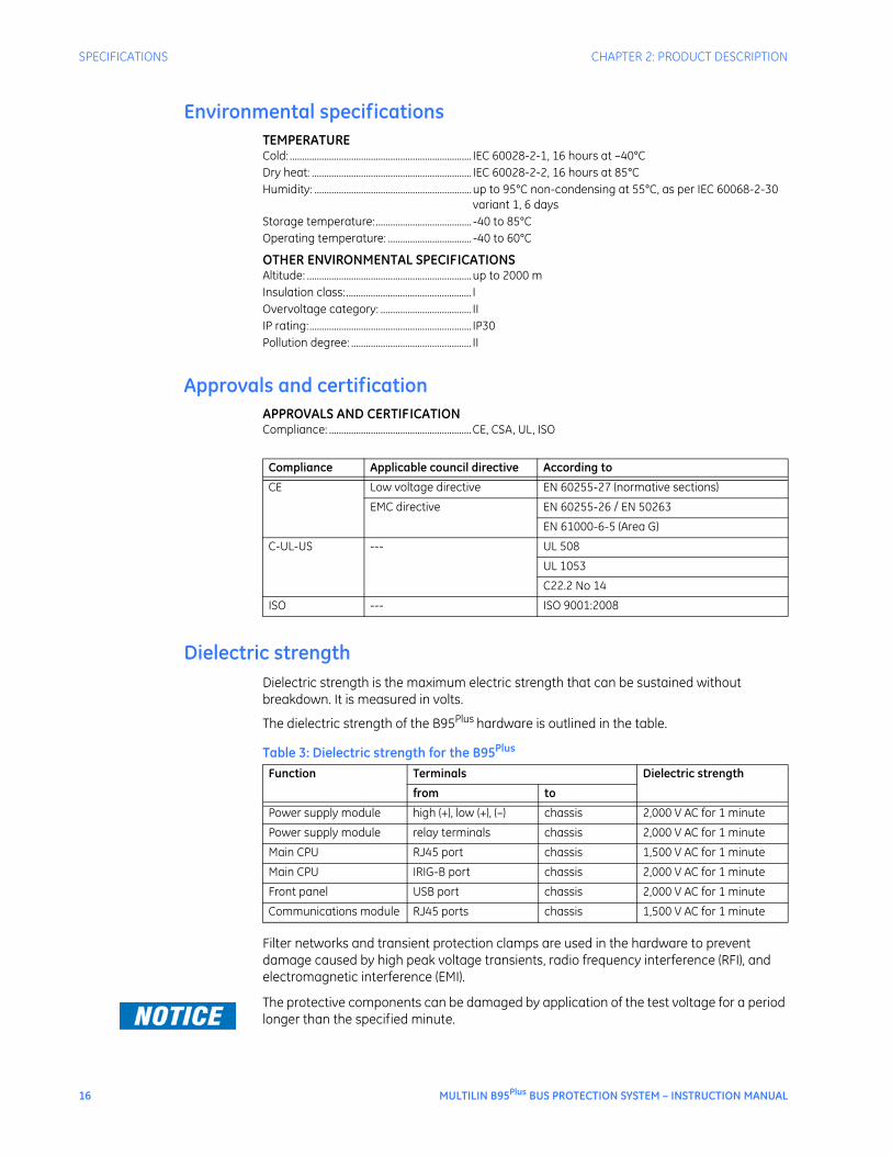
Environmental specificationsTEMPERATURECold: .......................................................................... IEC 60028-2-1, 16 hours at –40°CDry heat: ................................................................. IEC 60028-2-2, 16 hours at 85°CHumidity: ................................................................up to 95°C non-condensing at 55°C, as per IEC 60068-2-30
variant 1, 6 daysStorage temperature:....................................... -40 to 85°COperating temperature: .................................. -40 to 60°C
OTHER ENVIRONMENTAL SPECIFICATIONSAltitude: ...................................................................up to 2000 mInsulation class:................................................... IOvervoltage category: ..................................... IIIP rating:.................................................................. IP30Pollution degree: ................................................. II
Approvals and certificationAPPROVALS AND CERTIFICATIONCompliance: ..........................................................CE, CSA, UL, ISO
Dielectric strengthDielectric strength is the maximum electric strength that can be sustained without breakdown. It is measured in volts.
The dielectric strength of the B95Plus hardware is outlined in the table.
Table 3: Dielectric strength for the B95Plus
Filter networks and transient protection clamps are used in the hardware to prevent damage caused by high peak voltage transients, radio frequency interference (RFI), and electromagnetic interference (EMI).
FASTPATH: The protective components can be damaged by application of the test voltage for a period longer than the specified minute.
Compliance Applicable council directive According to
CE Low voltage directive EN 60255-27 (normative sections)
EMC directive EN 60255-26 / EN 50263
EN 61000-6-5 (Area G)
C-UL-US --- UL 508
UL 1053
C22.2 No 14
ISO --- ISO 9001:2008
Function Terminals Dielectric strength
from to
Power supply module high (+), low (+), (–) chassis 2,000 V AC for 1 minute
Power supply module relay terminals chassis 2,000 V AC for 1 minute
Main CPU RJ45 port chassis 1,500 V AC for 1 minute
Main CPU IRIG-B port chassis 2,000 V AC for 1 minute
Front panel USB port chassis 2,000 V AC for 1 minute
Communications module RJ45 ports chassis 1,500 V AC for 1 minute
16 MULTILIN B95Plus BUS PROTECTION SYSTEM – INSTRUCTION MANUAL
Multilin B95Plus Bus Protection System
Chapter 3: Installation
Installation
This section describes the physical and electrical installation of the Multilin B95Plus Bus Protection System.
Installing the unit in a rackThe B95Plus is a 19-inch horizontal rack-mount unit. The front faceplate is hinged to allow access to removable modules. This design allows the relay to be upgraded and repaired by qualified service personnel.
The cutout dimensions for panel mounting and case dimensions are shown in the following figures. When planning the location of your panel cutout, provide space for the faceplate to swing open from the top. Under normal operating conditions, the unit has no special cooling requirements, but adequate clearance must be provided to the bottom, sides, and top of the device to allow air to circulate. Do not block the ventilation openings of the chassis. Do not place other equipment or panels in such a way to obstruct airflow around the chassis.
The unit is typically installed in the control center.
To install the unit:
1. Mount the unit in a 19-inch rack such that the front faceplate sits semi-flush with the panel or switchgear door, allowing the operator access to the front panel keys and USB communications port. Leave a 1U (1 rack-unit) space below the chassis for ventilation and for the front panel to swing open from the top without obstruction. No extra space is required above the chassis. Clearance is provided by the shape of the mounting plate. Do not install other equipment or panels in such a way to obstruct this clearance.
2. Secure the unit to the panel using the four screws supplied with the relay.
3. Wire the unit as outlined in the Typical Wiring Diagram section.
MULTILIN B95Plus BUS PROTECTION SYSTEM – INSTRUCTION MANUAL 17
REAR TERMINAL AND PORT LAYOUT CHAPTER 3: INSTALLATION
Figure 1: Panel cutout dimensions
Figure 2: Dimensions
Rear terminal and port layoutThe back of the B95Plus chassis is shown in the figure.
18 MULTILIN B95Plus BUS PROTECTION SYSTEM – INSTRUCTION MANUAL
CHAPTER 3: INSTALLATION TYPICAL WIRING DIAGRAM
Figure 3: Rear terminal view
Printed circuit cards/modules are housed in slots. The slots are labelled from right to left: A, B, C, D, E, F, G, H, J, K. Active slots are as follows:
• Slot A — Contains the power supply module, which conditions the AC or DC station service power such that it is suitable for internal use, and contains the critical failure relay. Terminals on the power supply module are designated 1 thorough 10 with a slot letter (slot A) prefix.
• Slot C — Contains the communications card, which handles all station bus type Ethernet communications for the relay. The Ethernet ports on the communications card are port 2 on the top and port 3 on the bottom.
• Slot D — Contains the main card, which handles central processing tasks. Ports from top to bottom are IRIG-B and Ethernet port 1.
• Slot F — Optional — Same as slot J, if present
• Slot J — Contains a process card to connect to up to eight HardFiber Bricks and implement protection and control elements for 12 bus sources and two voltage sources. The port number assignments are two characters, assigned in order by card slot position (slot F or J) and the row number (1 through 8, top to bottom).
Other slots are empty.
Typical wiring diagramThis section outlines the electrical installation of the B95Plus. For Brick and fiber cable connections, see the HardFiber manual.
The unit can be connected to AC or DC power. Use of DC power is typical in the field.
MULTILIN B95Plus BUS PROTECTION SYSTEM – INSTRUCTION MANUAL 19
TYPICAL WIRING DIAGRAM CHAPTER 3: INSTALLATION
The following wiring diagram provides an example of how to wire the device. Actual wiring varies according to application.
Figure 4: Typical wiring diagram
IMPORTANT: Ensure that power is not live when connecting the wires to the unit, else injury or death can result.
To connect power:
1. Wire the unit according to the wiring diagrams.
After wiring the unit, to continue with installation skip ahead to Installing the EnerVista software section.
20 MULTILIN B95Plus BUS PROTECTION SYSTEM – INSTRUCTION MANUAL
CHAPTER 3: INSTALLATION POWER SUPPLY CARD (SLOT A)
Power supply card (slot A)The power supply card in slot A provides power to the unit. It can be connected to any of the following standard power sources:
• DC power — 110, 125, 220, or 250 V DC
• AC power — 115 or 230 V AC
Figure 5: Slot A on back of unit
The setup is shown schematically in the figure.
Figure 6: Control power connection
FASTPATH: Power supplied to the unit must be connected to the matching power supply terminal of the unit. If the voltage is applied to the wrong terminals, damage can occur.
FASTPATH: The B95Plus, like almost all electronic relays, contains electrolytic capacitors. These capacitors are well-known to be subject to deterioration over time if voltage is not applied periodically. Avoid deterioration by powering up the unit once a year.
MULTILIN B95Plus BUS PROTECTION SYSTEM – INSTRUCTION MANUAL 21
COMMUNICATIONS CARD (SLOT C) CHAPTER 3: INSTALLATION
The power supply card provides a critical failure relay, with form-C contacts that are energized once control power is applied and the relay successfully boots up with no critical self-test failures. If ongoing self-tests detect a critical failure or power is lost, then the critical failure relay de-energizes. This feature gives external indication when the relay has failed.
Extensive filtering and transient protection has been incorporated into the unit to ensure reliable operation in harsh industrial environments. Transient energy is removed from the relay and conducted to ground via the ground terminal. This terminal must be connected to the cubicle ground bus using a 10 AWG or larger stranded wire or ground braid. Do not daisy-chain grounds with other relays or devices. Each is to have an independent and direct connection to the ground bus.
The control power to the power supply card is protected by a non-replaceable 4 Amp slo-blo fuse. 14 AWG or larger stranded wire is recommended for control power connection. A ring terminal is recommended to ensure integrity of the connection. The rated torque for the terminal screw is 9 in lb (1 N m). External downstream disconnects and external overcurrent protection of 5 to 10 Amps are recommended for both control power inputs.
Communications card (slot C)The communications card has two Ethernet ports designated as ports 2 and 3. They allow the B95Plus to communicate at high speed (100 Mbps) with gateways, other relays, and computers running the EnerVista software. The ports are independent of each other. They run all protocols supported by the relay.
Each port supports IEEE 802.3 100Base-FX on an ST fiber connector and IEEE 802.3 100Base-TX on an RJ45 copper connector. Only one of these two Ethernet media types can be used on a given port at a given time; the relay automatically recognizes and uses the particular media connected on each port.
The optical fiber sizes supported are 50/125 µm and 62.5/125 µm; the wavelength is 1310 nm. IEEE 802.3 100Base-FX light levels are used, and as such can be connected directly to another 100Base-FX device without an attenuator. When splicing optical fibers, the diameter and numerical aperture of each fiber must be the same. In order to engage or disengage the ST connector, only a quarter turn of the coupling is required.
NOTE
NOTE: Ensure that the dust covers are installed when the fiber is not in use. Dirty or scratched connectors can lead to high losses on a fiber link.
The figure shows slots D and C on the rear of the unit.
22 MULTILIN B95Plus BUS PROTECTION SYSTEM – INSTRUCTION MANUAL
CHAPTER 3: INSTALLATION MAIN PROCESSOR CARD (SLOT D)
Figure 7: Slots D and C on rear of unit
Main processor card (slot D)The main processor module contains ports for Ethernet communications and IRIG-B connection.
Ethernet portEthernet ports allow the B95Plus to communicate at high speed (100 Mbps) with gateways and computers running the EnerVista software. The main processor card has one Ethernet port designated as port 1 to distinguish it from ports 2 and 3 on the communications card. Port 1 is typically used as the main Ethernet connection between the unit and the network. It is intended for engineering services, such as setting management and historical record retrieval, and so runs TFTP, FTP, HTTP, SNTP, and Modbus TCP/IP. This includes the ability to interface with the EnerVista B95Plus Setup software for settings management, monitoring, and recovering historical records.
The port supports IEEE802.3 100Base-FX on an ST fiber connector and IEEE 802.3 100Base-TX on an RJ45 copper connector. Only one of these two Ethernet media types can be used on the port at a given time; the relay automatically recognizes and uses the particular media connected.
The optical fiber sizes supported are 50/125 µm and 62.5/125 µm; the wavelength is 1310 nm. IEEE 802.3 100Base-FX light levels are used, and as such can be connected directly to another 100Base-FX device without an attenuator. When splicing optical fibers, the diameter and numerical aperture of each fiber must be the same. In order to engage or disengage the ST connector, only a quarter turn of the coupling is required.
CAUTION: Observing any fiber transmitter output can cause injury to the eye.
NOTE
NOTE: Ensure that dust covers are installed when the fiber is not in use. Dirty or scratched connectors can lead to high losses on a fiber link.
MULTILIN B95Plus BUS PROTECTION SYSTEM – INSTRUCTION MANUAL 23
PROCESS CARDS (SLOT J AND OPTIONALLY SLOT F) CHAPTER 3: INSTALLATION
IRIG-B portIRIG-B is a standard time code format that allows stamping of events to be synchronized among connected devices within one millisecond. The IRIG time code formats are serial, pulse width-modulated codes that can be either DC level shifted or amplitude modulated (AM).
Third-party equipment is available for generating the IRIG-B signal. This equipment can use a global positioning system (GPS) satellite system to obtain the time reference so that devices at different locations can also be synchronized.
Figure 8: IRIG-B connection
Other options are to use simple network time protocol (SNTP) and the internal clock.
For additional information, refer to:
Real time clock and IRIG-B on page 93
Process cards (slot J and optionally slot F)The unit comes with one or two process cards, these being slots J and F. They are used to connect to the GE HardFiber Bricks.
Each process card contains eight optical fiber Ethernet ports, each of which can interface with a Brick, through which the B95Plus acquires power system voltage and current waveform information, contact input information (such as isolator and breaker status), and through which the B95Plus issues breaker trip commands.
In B95Plus units with a single process card, the card is installed in slot J. In relays with two process cards, the cards are installed in slots F and J. Process card ports are designated with the card’s slot number followed by the port number on that card. The port numbers run from 1 through 8, top to bottom. For example, the top port on the process card in slot J is designated “J1,” and the bottom port on the process card in slot F is designated “F8.”
All process bus ports comply with IEC 802.3 100Base-BX, but with LC connectors and supporting multimode fiber. More detail on the fiber and the communications profile of IEC 61850 are contained in the HardFiber Process Bus System Reference Manual.
NOTE
NOTE: Ensure that the dust covers are installed when the fiber is not in use. Dirty or scratched connectors can lead to high losses on a fiber link.
24 MULTILIN B95Plus BUS PROTECTION SYSTEM – INSTRUCTION MANUAL
CHAPTER 3: INSTALLATION PROCESS CARDS (SLOT J AND OPTIONALLY SLOT F)
Figure 9: Process card J
MULTILIN B95Plus BUS PROTECTION SYSTEM – INSTRUCTION MANUAL 25
PROCESS CARDS (SLOT J AND OPTIONALLY SLOT F) CHAPTER 3: INSTALLATION
26 MULTILIN B95Plus BUS PROTECTION SYSTEM – INSTRUCTION MANUAL
Multilin B95Plus Bus Protection System
Chapter 4: EnerVista software
EnerVista software
The GE EnerVista software supplied with the Multilin B95Plus Bus Protection System provides tools to configure, monitor, maintain, and integrate information generated.
IntroductionThe EnerVista B95Plus Setup software provides a graphical user interface (GUI) to configure, monitor, and maintain the B95Plus connected locally to the computer or over local or wide area networks.
The software can be used in offline mode (not communicating with a B95Plus) or online mode (communicating with a B95Plus). In offline mode, a device settings file can be created or configured for eventual downloading to the B95Plus. In online mode, the current B95Plus settings can be browsed, individually modified, uploaded, or downloaded. In addition, the relay’s actual values can be monitored and historical records recovered and viewed utilizing real-time communication.
The EnerVista B95Plus Setup software is provided with every B95Plus relay and available for download on the GE website. It runs on computers with Microsoft Windows 2000 or later.
This chapter outlines how to install the software, then provides a summary of the software interface features. After installing the software, you connect via USB or Ethernet cables, and work your way through the menus to configure the B95Plus. The individual functions are described in subsequent chapters. Content of this manual is also contained in the online Help accessible from the main menu.
The following figure shows the main software window. The display depends on the features ordered, which means that features documented display in the software when the unit was purchased with them.
The software supports drag-and-drop functionality. For example, files dropped in the selected device in the Online Window area are sent automatically to the device.
MULTILIN B95Plus BUS PROTECTION SYSTEM – INSTRUCTION MANUAL 27
INSTALLING THE ENERVISTA SOFTWARE CHAPTER 4: ENERVISTA SOFTWARE
Figure 1: EnerVista software main window
Installing the EnerVista softwareThe software can be installed on a computer running Windows 2000 or later.
To install the EnerVista B95Plus Setup software from the Internet or the CD:
1. To download, access http://www.gedigitalenergy.com/multilin/. Use Product Lookup to navigate to the B95Plus page. Under Resources, select Software. Click the EnerVista B95Plus Setup software entry. Enter the requested information, then click the download button.
2. To install from the download or CD, locate and click the EnerVista B95Plus Setup file. The software installs in the directory selected and a shortcut to the Windows desktop and in the Windows start menu is created. Use either the desktop shortcut or start menu to launch the software.
Establishing communication via USBThe easiest way to establish communication between the EnerVista software and the B95Plus for the first time is to use the USB interface located on the front of the unit . Once established, you can then configure settings for the Ethernet ports.
28 MULTILIN B95Plus BUS PROTECTION SYSTEM – INSTRUCTION MANUAL
CHAPTER 4: ENERVISTA SOFTWARE ESTABLISHING COMMUNICATION VIA USB
Figure 2: Connecting computer to unit via USB
To set up the B95Plus using the USB port:
1. Turn on the computer and power up the B95Plus. The B95Plus takes a few minutes to start up and run self-tests; a test summary displays when ready.
2. With both the computer and B95Plus powered on, connect a USB cable between them. On the B95Plus, plug the cable into the lower port on the front panel.
3. The first time that the computer is connected, a hardware configuration wizard opens. Complete the wizard. For the driver location, browse to the EnerVista B95Plus Setup software location and locate the USB Driver folder that contains the SerialUSB.inf driver file. The path is typically C:\Program Files\GE Power Management\B95Plus\USB Driver, or for Windows 7 64-bit C:\Program Files\GE Power Management\B95Plus\USB Driver 64-bit If an error displays and the wizard does not complete, the Multilin Relay USB Serial Emulation driver software is being blocked. The following fix uses Windows XP Service Pack 3 as an example. Access the Control Panel application in Windows, then click System, click the Hardware tab, then click the Driver Signing button. Change the setting to Warn or Ignore (see figure). Then restart the hardware wizard in the Control Panel by clicking Administrative Tools, then Computer Management, then Device Manager, and search for the GE Protective Relay entry. Reinstall the driver.
MULTILIN B95Plus BUS PROTECTION SYSTEM – INSTRUCTION MANUAL 29
ESTABLISHING COMMUNICATION VIA USB CHAPTER 4: ENERVISTA SOFTWARE
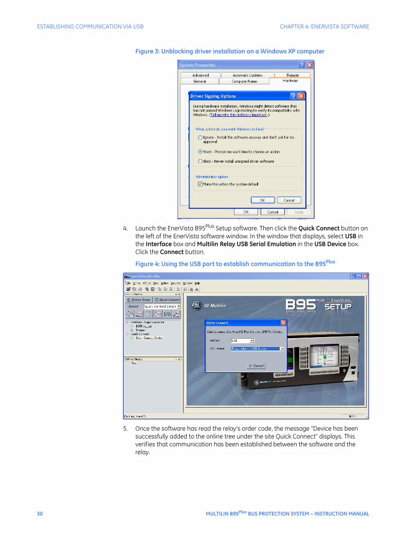
Figure 3: Unblocking driver installation on a Windows XP computer
4. Launch the EnerVista B95Plus Setup software. Then click the Quick Connect button on the left of the EnerVista software window. In the window that displays, select USB in the Interface box and Multilin Relay USB Serial Emulation in the USB Device box. Click the Connect button.
Figure 4: Using the USB port to establish communication to the B95Plus
5. Once the software has read the relay’s order code, the message “Device has been successfully added to the online tree under the site Quick Connect” displays. This verifies that communication has been established between the software and the relay.
30 MULTILIN B95Plus BUS PROTECTION SYSTEM – INSTRUCTION MANUAL
CHAPTER 4: ENERVISTA SOFTWARE ESTABLISHING COMMUNICATION VIA ETHERNET
Figure 5: Successful installation message
6. In the software, click OK and then expand the menu entry by clicking the + symbol beside an entry on the left side. You double-click a page name to open the panel. To continue configuring the unit, in the Online Window area on the left side of the software, access Settings and work your way through each panel. The software display depends on the B95Plus ordered; some features documented may not appear in your software interface. Use this document for information on each panel. Because the first panel is the Installation panel, skip ahead to that section. Leave the USB cable connected until you configure the IP address for the Ethernet port in the next section. You configure entries such as SNTP, Modbus, and DNP only if you intend to use them.
Figure 6: Starting configuration
Establishing communication via EthernetThere are two ways to establish communication for the first time between the EnerVista software on the computer and the B95Plus: USB port or Ethernet port. You typically connect using a USB cable, configure the IP addresses of the Ethernet port, then use Ethernet for regular use of the unit. This section describes how to connect via Ethernet.
There are two Ethernet cable options. Use standard (blue) Ethernet cables to connect the computer and the relay to the same Ethernet network. Or, use a crossover cable (typically red) to connect the computer directly to one of the relay’s Ethernet ports.
Port 1, which is the Ethernet port on the main processor card in slot D, is recommended for communication with the computer.
When using the crossover cable to connect the relay to the computer:
1. Manually configure Windows to use an IP address that is in the same subnet as the relay. A straight forward way to do this set the computer’s IP address to one count greater than that of the relay’s port. The computer’s subnet mask can be set to match the relay’s mask.
2. If computer settings have been changed to support direct connection via a crossover cable, restore them when finished with the connection.
MULTILIN B95Plus BUS PROTECTION SYSTEM – INSTRUCTION MANUAL 31
ADDING SITES AND DEVICES CHAPTER 4: ENERVISTA SOFTWARE
When using regular Ethernet cables to connect the relay and computer to a switched network, configure the relay’s Ethernet port settings with an IP address, subnet mask, and gateway address compatible with the network using the USB communications described in the preceding section. These settings are typically assigned by the network administrator and entered into the relay.
1. Connect the Ethernet cable to the back of the unit.
2. In the software, click the Quick Connect button on the left. In the window that displays, select Ethernet in the Interface box, and enter the relay’s IP address. Click the Connect button. The unit is now configured to communicate with the computer using Ethernet.
To view the relay’s IP address when the B95Plus is already in operation:
1. On the relay’s front panel, press the Next Page button below the annunciator display to the Communications Status page to view the IP address of the relay’s Ethernet port chosen for communication.
Figure 7: Viewing the IP address on the unit
CAUTION: Observing any fiber transmitter output can cause injury to the eye.
NOTE
NOTE: Ensure that dust covers are installed when the fiber is not in use. Dirty or scratched connectors can lead to high losses on a fiber link.
Adding sites and devicesThe EnerVista software allows for multiple B95Plus devices to be run from it. Communications parameters are organized in a hierarchical tree structure, with “sites” at the top level and devices (each a B95Plus) allocated to specific sites. Sites can contain any number of devices. There are four options to add sites and devices, as follows:
• The Device Setup button in the software window
• Right-clicking in the Online Window area of the software window and selecting Device Setup
• The Edit Device Setup icon on the tool bar
• Clicking the Online > Device Setup menu option
Use one of these options to configure the sites and devices now. One example follows.
To add a site and device to the software:
1. Click the Device Setup button.
2. Click the Add Site button in the window that opens.
3. Change the Site Name field to a descriptive name.
32 MULTILIN B95Plus BUS PROTECTION SYSTEM – INSTRUCTION MANUAL
CHAPTER 4: ENERVISTA SOFTWARE CONNECTING TO A DEVICE
4. Click the Add Device button.
5. Change the Device Name field to a descriptive name.
6. From the Interface drop-down list, select Ethernet to connect to the B95Plus device over a network.
7. Add the IP address.
8. Click the Read Order Code button.
9. Click OK to exit from the window.
Figure 8: Adding sites and devices
Once configured, online connection to a particular B95Plus can be established by navigating to the device in the Online Window area of the software. Files dragged and dropped into that part of the software window are sent automatically to the online communicating device.
Connecting to a deviceThe usual method to access a device is to click Quick Connect.
To access a device using the software:
1. In the Online Window area of the EnerVista software, double-click the Quick Connect menu item.
2. Double-click the Quick Connect Device menu item. The information loads.
Accessing settingsThree features facilitate selection and navigation:
• Quick select for operands
MULTILIN B95Plus BUS PROTECTION SYSTEM – INSTRUCTION MANUAL 33
ACCESSING SETTINGS CHAPTER 4: ENERVISTA SOFTWARE
• Screen navigation feature for long lists
• Expanding and collapsing a settings table
Operand quick selectUsing different mouse gestures, the user is able to initiate three different logic operand selection modes in the B95Plus, as follows:
• By right-clicking on the far right side of any logic operand setting entry field, a drop-down list of all logic operands opens. In this mode, the user can use the scroll-bar to scroll through the list until the required logic operand is visible, then click it to select it and close the list. The user can also type a letter on the keyboard to jump down the list to the next operand with a name starting with that letter.
• By right-clicking twice anywhere except the far right side of any logic operand setting entry field, the field opens for keyboard entry of the operand name. (The first click opens the operand quick select popup described as follows.) In this mode, as each character is typed, the characters to the right are replaced to match the first operand that matches the characters up to and including the new character. Characters that do not match an operand are not accepted. Windows operating system's select, copy and paste features also can be used in this mode.
• By single-clicking anywhere except the far right side of any logic operand setting entry field, the logic operand quick select window opens. The window is generally as shown in the figure that follows. The left-hand side displays a tree structure containing logical groups of operands, and the right-hand side shows the operands of the tree element selected. Double-clicking an operand in the right-hand window or single-clicking an operand and clicking Ok selects that operand and closes the window.
Figure 9: Accessing operands using quick select feature
Operands associated with process cards not present in the order code do not display. Operands associated with process cards that are present in the order code display whether or not they are associated with bricks that are disabled or not connected.
34 MULTILIN B95Plus BUS PROTECTION SYSTEM – INSTRUCTION MANUAL
CHAPTER 4: ENERVISTA SOFTWARE VIEWING ACTUAL VALUES
Navigating long listsFor tables with many columns, a feature allows you to navigate quickly to a column.
The feature uses the Parameter and ID fields at the top of the table. Simply click the Parameter field to select a column to which to navigate. Or select the ID field and select a specific entry. For both fields, you can also type a letter to have the software jump to the first entry starting with that letter. To exit without selecting, press the Esc key.
In the example shown, ID was clicked and there are two options from which to select, CB3 and CB5.
Figure 10: Using the drop-down list to navigate columns
Expanding/collapsing table rowsFor tables in the EnerVista software with numerous rows, the rows are generally collapsed when the window opens. Simply click the row heading, which is typically a grey box with bold text, to expand content. In the example shown, the General Settings rows have been expanded.
The ID row at the top of the table is always expanded and cannot be collapsed.
Figure 11: Bus sources settings
Viewing actual valuesActual values refers to live data. You can view real-time data from the B95Plus, such as input/output status and measured parameters.
To view data:
1. In the Online Window area of the EnerVista software, navigate to the Actual Values entry.
MULTILIN B95Plus BUS PROTECTION SYSTEM – INSTRUCTION MANUAL 35
VIEWING EVENT RECORDS CHAPTER 4: ENERVISTA SOFTWARE
Information on actual values is outlined in applicable sections later in this document.
Viewing event recordsThe events recorder in the B95Plus provides a time-stamped record of state changes of signals monitored by the unit. These signals can include the state of circuit breakers and disconnect switches, external alarms and indications, and any of the internal functions of the device. The B95Plus can store a total of 4,096 events on the main card and 4,096 events on each process card. Once this memory is filled, the oldest events are overwritten. Events are displayed in chronological order from most recent to oldest.
Most B95Plus elements contain an events setting. Event recording is enabled by default for most functions, and state changes for FlexLogic operands associated with the element are written to the events recorder. When the setting is disabled, state changes for the element are not recorded.
The following procedures outline how to view event records and enable/disable event recording. See the Event Recorder section later in the document for information on how to compare event records and how to access the records on the B95Plus.
To view the event records of a B95Plus device:
1. In the Online Window area of the EnerVista software, navigate to Actual Values > DFR > Event Record. The event record displays.
2. Click the Refresh button whenever the screen needs to be updated with the recent events.
Figure 12: Viewing event records
An example follow for enabling/disabling event recording.
To enable/disable bus differential event recording of a B95Plus device:
1. In the Online Window area of the EnerVista software, navigate to Settings > Protection > General > Bus Differential.
2. View the Events field.
36 MULTILIN B95Plus BUS PROTECTION SYSTEM – INSTRUCTION MANUAL
CHAPTER 4: ENERVISTA SOFTWARE VIEWING TRANSIENT RECORDS
Viewing transient recordsTransient records are detailed data records covering short periods of time. The B95Plus records up to 128 samples per cycle for the transient records. EnerVista includes the ability to view oscillography waveform traces and digital states in a visual display of power system and relay operation data for specific triggered events.
To view transient records in the software:
1. In the Online Window area, navigate to Actual Values > DFR > Transient Recorder, select the required record, and click the Read button to recover the record and start the Comtrade waveform viewer. The records can also be retrieved from the EnerVista software event record screen by double-clicking the transient record’s icon, which is located on the right side of the event record window.
Figure 13: Transient record retrieval screen
To manually force a trigger of the transient recorder, use the transient retrieval screen shown. Click the Force Trigger button.
To clear transient records, use the Actual Values > DFR > Transient Recorder > Command screen.
Settings filesSettings files contain device and configuration information. They are used to apply new settings to devices, or to restore previously saved settings. They are organized by file names assigned by the user. Settings files contain data pertaining to the following types of relay settings:
• Device definition
• General
• Communications (station bus interface)
• Remote resources (process bus interface)
• Protection (protection elements, FlexLogic, Isolators, Group Control)
• Digital fault recorder (DFR), including transient recorder and Event Recorder
MULTILIN B95Plus BUS PROTECTION SYSTEM – INSTRUCTION MANUAL 37
DEPLOYING SETTINGS FILES TO MULTIPLE DEVICES USING SETTINGS TEMPLATES CHAPTER 4: ENERVISTA SOFTWARE
The EnerVista software supports the following three ways of handling changes to relay settings:
• In offline mode (relay disconnected) to create or edit relay settings files for later download to communicating relays
• In online mode (relay connected) to directly modify any relay settings via relay data view windows, and then later save the settings to a file
• Create/edit settings files offline while connected to the relay, then write them to the relay
Factory default values are supplied and can be applied after any changes.
The following settings are not transferred to the B95Plus with settings files:
• Relay Settings Programmed/Not Programmed
• Modbus TCP Port Number
• IP Address
• IP Subnet Mask
• Gateway IP Address
• Network Address NSAP
• IEC61850 Config GOOSE ConfRev.
Deploying settings files to multiple devices using settings templates
Settings templates simplify the configuration of multiple devices that protect similar assets. In these situations, typically a large number of settings are identical among devices, reflecting a common bus architecture and protection approach. The templates allows engineers to configure and test these common settings, then lock them so they are not available to others. For example, these locked-down settings can be hidden from view to field engineers, allowing them to quickly identify and concentrate on the settings specific to their application. The site-specific settings can be specified as editable and made available to field engineers installing the devices. These are settings such as protection element pickup values and current transformer (CT) and voltage transformer (VT) ratios.
The settings template mode allows the user to define which settings are visible in the EnerVista B95Plus Setup software. Settings templates can be applied to both settings files (settings file templates) and online devices (online settings templates). The functionality is identical for both purposes. When in template mode, only settings that are available for editing are saved to the device or setting file during the read/write process.
This section outlines how to enable and edit the templates.
Enabling the settings template in offline modeThe settings file template feature is disabled by default.
To enable the settings template while in offline mode:
1. Select a settings file from the Offline Window area of the EnerVista software.
2. Right-click the selected settings file and select Settings File Template > Create Template. When the option does not display, it means that the template is already enabled.
38 MULTILIN B95Plus BUS PROTECTION SYSTEM – INSTRUCTION MANUAL
CHAPTER 4: ENERVISTA SOFTWARE DEPLOYING SETTINGS FILES TO MULTIPLE DEVICES USING SETTINGS TEMPLATES
The settings file template is now enabled and the file tree displayed in light blue. The settings file is now in template editing mode (shown).
Figure 14: Enabled settings template
Enabling the settings template in online modeThe settings file template feature is disabled by default.
To enable the settings template while in online mode:
1. Select an installed device in the Online Window area of the EnerVista software.
2. Right-click the device and select Template Mode > Create Template. If the option does not display, it means that the template is already enabled.
Figure 15: Enabling the template
3. In the password window that appears, enter and re-enter a password, then click OK. The password is for the template and must be at least four characters in length.
Figure 16: Entering a settings file password
The online settings template is now enabled. The device is now in template editing mode.
MULTILIN B95Plus BUS PROTECTION SYSTEM – INSTRUCTION MANUAL 39
DEPLOYING SETTINGS FILES TO MULTIPLE DEVICES USING SETTINGS TEMPLATES CHAPTER 4: ENERVISTA SOFTWARE
Editing a settings templateThe template editing feature is used to specify which settings are available for viewing and modification in the EnerVista software. By default, all settings except the FlexLogic equation editor settings are locked.
To edit a settings file template:
1. Right-click an installed device or a settings file on the left side of the EnerVista software.
2. Select Template Mode > Edit Template (online mode) or Settings File Template > Edit Template (offline mode) to place the device or settings file in template editing mode.
3. Enter the template password (if required) then click OK.
4. Navigate to and select the relevant settings windows that contain settings to be specified as viewable. In the example shown, Protection > General > Bus Sources was selected.
By default, settings specified as locked display with a grey background. The Edit icon on the upper right of the settings window indicates that software is in edit mode.
5. Specify which settings to make viewable by clicking them.
The settings selected as available to view display in yellow.
6. Click Save to save changes to the settings template.
Only the settings that are available for editing are saved to the device or setting file.
Adding password protection to a settings templateTo maximize security, save a template with password protection.
To add password protection to a settings file template:
1. Right-click a settings file in the Offline Window area of the EnerVista software.
40 MULTILIN B95Plus BUS PROTECTION SYSTEM – INSTRUCTION MANUAL
CHAPTER 4: ENERVISTA SOFTWARE DEPLOYING SETTINGS FILES TO MULTIPLE DEVICES USING SETTINGS TEMPLATES
2. Select Settings File Template > Password Protect Template. When the option is not available, it means that the template is not active or that a password already exists. To activate the template, select the Create Template option.
Figure 17: Template password entry window
3. In the password window that appears, enter and re-enter a password, then click OK. The password is for the template and must be at least four characters in length.
The settings file template is now secured with password protection.
NOTE
NOTE: When templates are created for online settings, the password can be added during the initial template creation step. It does not need to be added after the template is created.
Applying a settings templateOnce all necessary settings are specified for viewing, users can use the settings template on the online device or the settings file.
To display only the settings available for editing:
1. Right-click an installed device or a settings file at the left side of the EnerVista software.
2. Select Template Mode > View in Template Mode (online mode) or Settings File Template > View in Template Mode (offline mode).
3. Enter the template password (if required) then click OK to apply the template.
Once the template has been applied, users are only able to view and edit the settings specified by the template. The effect of applying the template to the bus source settings is shown. The white fields can be changed. The grey fields cannot be changed.
Figure 18: Setting window view via the View in Template Mode command
Viewing in template mode also modifies the panels displayed in the software, showing only the settings categories that contain editable settings. The effect of applying the template is shown as follows. In the first figure the template has not been applied and all menu items display. In the second figure, the template has been applied and only the Bus Source item displays.
MULTILIN B95Plus BUS PROTECTION SYSTEM – INSTRUCTION MANUAL 41
BUS REPLICA GRAPHICAL EDITOR CHAPTER 4: ENERVISTA SOFTWARE
Figure 19: Settings template not applied
Figure 20: Settings template applied
Removing a settings templateIt can be necessary to remove a settings template. Upon removal, it cannot be reapplied and a new settings template is required.
To remove a template:
1. Right-click an installed device or settings file on the left side of the EnerVista software.
3. Enter the template password (if required) and click OK to continue.
4. Verify that you want to remove the template by clicking Yes.
Figure 21: Confirming settings template removal
The EnerVista software removes all template information and all settings are available.
Bus replica graphical editorA bus replica graphical editor is provided as an alternate means of entering settings and visualizing the behavior of the bus replica. The bus replica is the means by which the determines moment-by-moment the extent of each differential zone, as detailed in later chapters. Dynamic buses in particular elicit complex bus replica behavior, which can be difficult to visualize using only the usual matrixes of settings. Graphical presentation facilitates visualization.
42 MULTILIN B95Plus BUS PROTECTION SYSTEM – INSTRUCTION MANUAL
CHAPTER 4: ENERVISTA SOFTWARE BUS REPLICA GRAPHICAL EDITOR
The graphical editor operates on settings related to configuring the bus replica. Basically, the graphical editor allows a schematic diagram of the protected bus to be constructed, and by clicking on the isolators, breakers, and CTs in the diagram, settings entered that fit the diagram to the actual bus. These settings are the same settings that can also be configured by the usual methods from screens containing matrixes of settings, although there are restrictions on opening both the matrix screens and the graphical editor at the same time. The graphical editor also has a few "virtual settings" concerning the graphical presentation that are not accessible from the matrix screens, but none of these affect relay operation.
This section contains instructions on the use of the graphical editor. The effect of the settings the graphical editor accesses on relay behavior and guidance on setting their values are contained in following chapters.
The bus graphical editor does not display dynamic open/close status of the isolators and breakers. It displays only how they are arranged.
NOTE
NOTE: The bus replica graphical editor displays only bus sources that are selected for display. It is possible for enabled bus sources that therefore are contributing to protection operation to be omitted from the display, and as a result their contribution overlooked by personal using the display. Verification of the presence on the graphical display of all bus sources shown as enabled on the Settings > Protection > General > Bus Sources screen is highly recommended.
The following figure shows as an example a completed diagram. The wide short boxes stacked vertically on the left side are bus zone labels, the horizontal lines extending from them to the right are each a bus zone representation. The tall boxes to the right are each a representation of a bus source.
MULTILIN B95Plus BUS PROTECTION SYSTEM – INSTRUCTION MANUAL 43
BUS REPLICA GRAPHICAL EDITOR CHAPTER 4: ENERVISTA SOFTWARE
Figure 22: Bus replica graphical editor example
44 MULTILIN B95Plus BUS PROTECTION SYSTEM – INSTRUCTION MANUAL
CHAPTER 4: ENERVISTA SOFTWARE BUS REPLICA GRAPHICAL EDITOR
The following figure shows the symbols used in each bus source representation. The back-slash ("\") symbols represent bus or bypass isolators, the solid squares represent circuit breakers, the triangles represent network elements, and the double arc symbols represent CTs.
Figure 23: Symbols used in a bus source
An isolator can display three ways. First, it is greyed-out when its dynamic status connection setting is set to OFF (for example if there is a permanent primary open circuit at that position). To set it to OFF, you double-click the isolator and select the “Isolator Does Not Exist" option. Second, when you select the “Solid Connection” option, the isolator is ON and displays as a straight-through connection (for example if there is a permanent primary connection in that isolator's position). Third, the isolator displays as a disconnected slash when the setting is set to any logic operand other than OFF or ON (for example if there is an actual primary isolator at that position).
Figure 24: Setting an isolator as on or off
MULTILIN B95Plus BUS PROTECTION SYSTEM – INSTRUCTION MANUAL 45
BUS REPLICA GRAPHICAL EDITOR CHAPTER 4: ENERVISTA SOFTWARE
A circuit breaker is greyed-out when its breaker opened settings are both set to OFF, indicating that the zone expansion/reduction feature is not deployed.
The CT drawing convention used here is that an instantaneously positive primary current entering one side of the CT symbol results in an instantaneously positive secondary current exiting the same side of the CT symbol. That is to say, if polarity marks were to be drawn on the symbol, then primary and secondary marks are on the same side of the symbol. The side of the CT with the longer tail represents the side of the CT that connects to the Brick. Thus when the tail is on the side away from the bus, primary current flowing into the bus results in a positive relay current. If the CT origin settings are both None (meaning there is no actual CT), the CT symbol is greyed-out.
To configure the bus replica using the bus replica graphical editor:
1. In the Online Window area of the software, navigate to Settings > Protection > General > Bus Replica Graphical Editor.
2. Double- click the bus zone label of each bus zone to be used, and in the Bus Zone Properties window that opens, enter an ID descriptive of the bus segment to be protected. Also select the required function and zone type setting. Click OK to close the window.
3. Add the required bus sources. To add a bus source to the right of all existing sources on the diagram, click the icon at the top right of the window shown in the following figure. To add a bus source to the left of an existing source, right-click the existing source and select the Insert Bus Source option.
4. In the Bus Source Properties window that opens on adding a bus source, select the designation of the required bus source from the Source drop-down list. Next, while still in the Bus Source Properties window, enter an ID descriptive of the bay modelled by the bus source. Also select the required function and events setting, and the operand to use for bus source block feature. Select the appropriate Graphical Presentation icon that best represents the arrangement of the CTs and breaker in the bus source. Click OK to close the window.
5. Double-click each of the isolator, breaker, and CT symbols, and in the window that open, adjust the presented settings appropriately.
46 MULTILIN B95Plus BUS PROTECTION SYSTEM – INSTRUCTION MANUAL
CHAPTER 4: ENERVISTA SOFTWARE SECURING AND LOCKING FLEXLOGIC EQUATIONS
6. Double-click anywhere inside a bus source except over an isolator, CT, or breaker to re-open the Bus Source Properties window when bus source setting changes are required.
7. Right-click a bus source and select the Hide Bus Source option to remove a bus source no longer wanted in that position on the diagram. This action does not disable the bus source; it only removes the bus source from the diagram. Once removed, a bus source can be inserted in a different location as described in step 3.
Note that the Copy Special option copies the diagram to the Windows paste buffer as a bitmap. The bitmap can then be pasted into other documents using programs such as Word or Paint.
Securing and locking FlexLogic equationsThe B95Plus allows users to secure parts or all of a FlexLogic equation, preventing unauthorized viewing or modification of critical FlexLogic applications.
This is accomplished using the settings template feature to lock individual entries within FlexLogic equations. Secured FlexLogic equations remain secure when files are sent to and retrieved from any B95Plus device.
Use the following procedures.
Locking FlexLogic equation entriesTo lock individual entries of a FlexLogic equation:
1. Right-click the settings file or online device on the left side of the EnerVista software. and select Template Mode > Edit Template. If the template has not already been enabled, click Settings File Template > Create Template or Template Mode > Create Template.
2. In the same navigation tree, navigate to Settings > Protection > Main Card FlexLogic > FlexLogic Equation Editor.
By default, all FlexLogic entries are viewable and display against a yellow background. The icon on the upper right of the window indicates that the software is in edit mode.
3. Specify the entries to lock by clicking them.
The locked entries display against a grey background.
Figure 25: Locking FlexLogic entries using the template
4. Click the Save button.
MULTILIN B95Plus BUS PROTECTION SYSTEM – INSTRUCTION MANUAL 47
Locking a settings file and FlexLogic equations to a serial numberA settings file and associated FlexLogic equations can be locked to a B95Plus serial number. Once the FlexLogic entries in a settings file have been secured, use the following procedure to lock the settings file to a serial number.
1. Right-click the settings file in the Offline Window area and select Manage Settings File > Edit Properties.
The following window displays.
Figure 26: Locking the settings file to a device
2. Enter the serial number of the B95Plus device to lock to the settings file in the Serial # Lock field. To view the serial number, look for the bar code on the back of the unit, navigate to Actual Values > Product Information > Model Information in the Online Window area of the software, or page down in the annunciator display on the front of the unit.
3. Click OK. The settings file and FlexLogic equations are now locked to the B95Plusdevice specified.
Settings file traceabilityA traceability feature allows the user to determine if the settings in a B95Plus device have been changed since installation from a settings file.
To determine if settings have changed since installation:
1. Simply right-click in the Online Window area and select Compare with Settings File. The number of differences then a list of differences displays.
48 MULTILIN B95Plus BUS PROTECTION SYSTEM – INSTRUCTION MANUAL
50 MULTILIN B95Plus BUS PROTECTION SYSTEM – INSTRUCTION MANUAL
Multilin B95Plus Bus Protection System
Chapter 5: Settings – General
Settings – General
This chapter and subsequent chapters on Communications, Remote Resources, Protection, Digital Fault Recorder, Front Panel, and Security describe features on a presentation structure that facilitates comprehension by the settings engineer. This chapter describes general features whose settings appear in the software under Settings > General.
InstallationAfter installation of the Multilin B95Plus Bus Protection System, installation of the EnerVista software, and addition of the B95Plus device to the software, start configuration of the device with the relay name.
To configure or view installation information:
1. In the Online Window area of the software, navigate to Settings > General > Installation.
2. Click the right side of a field to access any drop-down list, for example to the right of “Not Programmed.” Otherwise, click a field to change the setting.
3. Click Save when done.
Figure 1: General installation information
The following settings are available.
MULTILIN B95Plus BUS PROTECTION SYSTEM – INSTRUCTION MANUAL 51
POWER SYSTEM CHAPTER 5: SETTINGS – GENERAL
Relay SettingsRange: Programmed, Not ProgrammedDefault: Not Programmed
To safeguard against the installation of a device without any entered settings, the B95Plus does not allow signaling of any output relay until this setting value is “Programmed.” The UNIT NOT PROGRAMMED self-test error message displays on the front panel self-test summary page until it is put into the programmed state. Normally, you set the value to “Programmed” after configuring all the Settings panels and the unit is ready to go into service. You do this manually while online using this field; downloading a settings file does not change this setting.
Relay NameRange: up to 20 charactersDefault: -----
This setting allows the user to uniquely identify a relay. This name appears on all generated reports and displays and on the front panel Product Information page as the Relay ID.
User Configuration NameRange: up to 20 charactersDefault: Initial
This setting allows the user to provide a description for the settings that are loaded at a particular time (for example, “Spring-summer settings”). This description displays on the Product Information page of the front panel as the Configuration field.
User Configuration DateRange: up to 20 charactersDefault: -----
This setting records the date of last setting change through the B95Plus software. Each time any settings are changed or a new settings file loaded, this value updates. This description also displays on the front panel Product Information page as the Configuration Date.
Power systemThe power system includes the following items: nominal frequency; frequency tracking function; frequency and phase reference; current cutoff level; and voltage cutoff level. Configure these for first setup.
To configure or view power system information:
1. In the Online Window area of the software, navigate to Settings > General > Power System.
Figure 2: Frequency and voltage information
52 MULTILIN B95Plus BUS PROTECTION SYSTEM – INSTRUCTION MANUAL
This value is used as a default to set the digital sampling rate if the system frequency cannot be measured from available signals. This can happen if the Frequency Tracking Function is Disabled, the Frequency and Phase Reference setting is None, or the signals are not present or are heavily distorted. Before reverting to the nominal frequency, the frequency tracking algorithm holds the last valid frequency measurement for a safe period of time while waiting for the signals to reappear or for the distortions to decay.
Frequency Tracking FunctionRange: Disabled, EnabledDefault: Enabled
This setting is set to “Disabled” only in unusual circumstances; consult GE Multilin for special variable-frequency applications.
Frequency And Phase ReferenceRange: None, all bus sources, and all voltage sourcesDefault: None
This setting determines which signal source is used (and hence which AC signal) for frequency tracking and phase angle reference. The Clarke transformation of the phase signals is used for frequency metering and tracking (VFREQ = (2VA – VB –VC) / 3) for better performance during fault, open pole, and voltage transformer (VT) and current transformer (CT) fail conditions.
The reference signal phase angle always displays zero degrees and all other phase angles are relative to this signal. If the pre-selected reference signal is not measurable at a given time, the phase angles are not referenced and typically continuously rotate.
The phase angle referencing is done via a phase locked loop, which can synchronize independent B95Plus devices if they have the same AC signal reference. This results in precise correlation of time tagging in the event recorder between different devices during periods of IRIG-B unavailability. Note that the other devices are not typically B95Plus units; they are UR or URPlus devices or from other vendors.
Current Cutoff LevelRange: 0.002 to 0.020 per unit (pu) in steps of 0.001Default: 0.020 pu
This setting modifies the current cutoff threshold. Very low currents (0.2 to 2% of the rated value) are very susceptible to noise. Some customers prefer low currents to display as zero, while others prefer the current to be displayed even when the value reflects noise rather than the actual signal. The B95Plus applies a cutoff value to the magnitudes and angles of the measured currents. If the magnitude is below the cutoff level, it is substituted with zero. This applies to phase current phasor values. The cutoff operation applies to quantities used for metering, general protection, and control, as well as those used by communications protocols. Raw current samples available via oscillography are not subject to cutoff.
The bus differential algorithm does not use cutoff.
NOTE
NOTE: Lower this setting with care because the B95Plus accepts lower signals as valid measurements. Unless dictated otherwise by a specific application, the default setting of “0.020 pu” is recommended.
MULTILIN B95Plus BUS PROTECTION SYSTEM – INSTRUCTION MANUAL 53
USER PROGRAMMABLE SELF-TESTS CHAPTER 5: SETTINGS – GENERAL
Voltage Cutoff LevelRange: 0.1 to 1.0 volts secondary in steps of 0.1Default: 1.0 volts secondary
This setting specifies the voltage cutoff threshold. Low secondary voltage measurements (at the fractional volt level) can be affected by noise. Some customers prefer these low voltages to be displayed as zero, while others prefer the voltage to be displayed even when the value reflects noise rather than the actual signal. The B95Plus applies a cutoff value to the magnitudes and angles of the measured voltages. If the magnitude is below the cutoff level, it is substituted with zero. This operation applies independently to phase voltages and to phase-to-phase voltages. The cutoff operation applies to quantities used for metering, protection, and control, as well as those used by communications protocols. Raw samples of the voltages available via oscillography are not subject cutoff.
NOTE
NOTE: Lower this setting with care because the B95Plus accepts lower signals as valid measurements. Unless dictated otherwise by a specific application, the default setting of “1.0 V” is recommended.
User programmable self-testsThe B95Plus performs self-tests to verify relay integrity. There are the two types of self-tests: major and minor. These tests are itemized in the Maintenance chapter. The settings described in this section allow certain self-tests to be enabled or disabled to meet requirements of the application.
To configure self-tests:
1. In the Online Window area of the software, navigate to Settings > General > User Programmable Self Test.
Figure 3: Self-test settings
The following settings are available.
Remote Device Off FunctionRange: Enabled, DisabledDefault: Enabled
When this setting is Enabled, the REMOTE DEVICE OFF self-test operates as described in the minor self-tests section of the Maintenance chapter. When Disabled, this self-test does not alarm.
54 MULTILIN B95Plus BUS PROTECTION SYSTEM – INSTRUCTION MANUAL
CHAPTER 5: SETTINGS – GENERAL USER PROGRAMMABLE SELF-TESTS
Ethernet Port 1…3 Fail FunctionRange: Enabled, DisabledDefault: Disabled
When this setting is Enabled, the ETHERNET PORT 1…3 FAILURE self-tests operate as described in the minor self-tests section of the Maintenance chapter. When Disabled, this self-test does not alarm.
When this setting is Enabled, the SNTP FAILURE self-test operates as described in the minor self-tests section of the Maintenance chapter. When Disabled, this self-test does not alarm.
When this setting is Enabled, the IRIG-B FAILURE self-test operates as described in the minor self-tests section of the Maintenance chapter. When Disabled, this self-test does not alarm.
Configurable Major Self-TestRange: any FlexLogic operandDefault: OFF
When the operand selected by this setting is in the On state, this self-test is alarmed. This allows the relay to use FlexLogic or other means to generate an application specific major self-test alarm, thereby taking the relay out of service.
MULTILIN B95Plus BUS PROTECTION SYSTEM – INSTRUCTION MANUAL 55
USER PROGRAMMABLE SELF-TESTS CHAPTER 5: SETTINGS – GENERAL
56 MULTILIN B95Plus BUS PROTECTION SYSTEM – INSTRUCTION MANUAL
Multilin B95Plus Bus Protection System
Chapter 6: Communications
Communications
This chapter outlines how to program the Multilin B95Plus Bus Protection System communication settings.
Communications overviewThe B95Plus has one Ethernet port (port 1) on the main module and two additional Ethernet ports (ports 2 and 3) on the communications module. Each port supports 100Base-FX over multimode fiber and 10/100Base-TX over twisted-pair, with auto-negotiation. Port 1 is primarily intended for configuration and file retrieval purposes. Ports 2 and 3 are intended for supervisory control and acquisition data (SCADA) and peer-to-peer messaging. The following protocols are available, depending on the order code of the unit.:
Network settingsThis section outlines configurable network settings, such as Ethernet, trivial file transfer protocol (TFTP), and simple network time protocol (SNTP).
EthernetEach of Ethernet ports 1 to 3 have globally unique identifiers known as MAC addresses. The MAC address of port 1 is displayed on the Product Information page of the annunciator and in the EnerVista software under Actual Values > Product Information > Model Information. The MAC address of port 2 is one greater than port 1, and the MAC address of port 3 is one greater than port 2.
If not already done, configure the IP address of the B95Plus and enable the Ethernet ports for use. Ethernet ports 2 and 3 can be configured for single or dual IP redundancy.
MULTILIN B95Plus BUS PROTECTION SYSTEM – INSTRUCTION MANUAL 57
NETWORK SETTINGS CHAPTER 6: COMMUNICATIONS
In the single IP redundancy configuration, the port 2 IP address, subnet mask, and gateway address are used for both ports 2 and 3, and the port 3 settings are ignored. All communications traffic are normally routed on port 2. If a failure occurs (determined at the hardware layer upon detecting loss of link signal on the active channel) then the traffic is re-routed to port 3. Switchover to port 3 takes place in less than 10 ms from the moment that the physical layer detects a failure. The device reverts from port 3 to port 2 as soon as port 2 becomes available, regardless of the state of port 3. Switchover to port 2 takes place in less than 500 ms. A link pulse is maintained in the transmit direction on both ports regardless of the port in use. This ensures that communications are established with minimal delays. An Ethernet broadcast message is transmitted immediately upon port switch, thereby forcing all Ethernet switches in the network to immediately update their routing tables.
In the dual IP redundancy configuration, each port has a unique IP address, with separate subnet mask, and gateway address settings. Multiple client-server connections can be opened on each port simultaneously. Under normal conditions, GOOSE messages are sent on both ports and received on either.
To configure Ethernet settings:
1. In the Online Window area of the software, navigate to Settings > Communications > Network > Ethernet to open the Ethernet configuration window.
2. After entering the addresses and settings, click the Save button then the Apply button.
Figure 1: Configuring Ethernet ports
The IP addresses are used with the DNP, Modbus/TCP, IEC 61580 MMS services, IEC 60870-5-104, SNTP, and TFTP protocols.
58 MULTILIN B95Plus BUS PROTECTION SYSTEM – INSTRUCTION MANUAL
CHAPTER 6: COMMUNICATIONS NETWORK SETTINGS
NOTE
NOTE: When the NSAP address or any user map setting (when used with DNP) is changed, it becomes active after power to the relay has been cycled (off-to-on).
The following settings are available for each Ethernet port, except for OSI Network Address (NSAP) and ESH Configuration Timer, which are not port-specific, and the Port 2 Redundancy, which applies only to Ethernet port 2.
Port 1, Port 2, Port 3 IP AddressRange: standard IP address rangeDefault: 192.168.251.251 (port 1), 192.168.252.252 (port 2), 192.168.253.253 (port 3)
These settings specify the dedicated IP address for each Ethernet port. Each port must be configured for a different subnet. The IP address setting for port 3 is not available when the Port 2 Redundancy setting is “Single IP.”
Port 1, Port 2, Port 3 IP Subnet MaskRange: standard IP subnet mask rangeDefault: 255.255.255.0
These settings specify the dedicated subnet mask for each Ethernet port. Each port must be configured for a different subnet, though the subnet masks can be identical.
The subnet mask setting for port 3 is not available when the Port 2 Redundancy setting is “Single IP.”
Port 1, Port 2, Port 3 Gateway IP AddressRange: standard IP address rangeDefault: 0.0.0.0
These settings specify the gateway address for the selected Ethernet port. The setting 0.0.0.0 codes no gateway. Configure only one gateway for the relay and be sure to configure this setting when using FTP and/or SNTP. Because only one port can declare a gateway, the port selected in the SNTP settings is the port to declare the gateway address.
The gateway IP address setting for port 3 is not available when the Port 2 Redundancy setting is “Single IP.”
Port 1, Port 2, Port 3 Ethernet ModeRange: Auto, 10/100 Base-TX, 100 Base-FXDefault: Auto
These settings select the Ethernet connection hardware type, either 10/100Base-TX (twisted-pair) or 100Base-FX (fiber optic). The “Auto” selection is used to automatically detect the Ethernet hardware type.
The Ethernet mode setting for port 3 is not available when the Port 2 Redundancy setting is “Single IP.”
Port 2 RedundancyRange: Single IP, Dual IPDefault: Dual IP
This settings selects single-IP or dual-IP operation for Ethernet ports 2 and 3. In single-IP mode, the link status of both ports is continuously monitored but only one port is active at a time. Each port uses the same source MAC address and IP parameters specified for Ethernet port #2. In dual-IP mode, Ethernet ports 2 and 3 operate independently with their own MAC addresses and IP parameters. Changes to this setting are implemented immediately on saving.
This setting specifies the NSAP address used with the IEC 61850 GSSE protocol over the OSI (CLNP/TP4) stack.
MULTILIN B95Plus BUS PROTECTION SYSTEM – INSTRUCTION MANUAL 59
NETWORK SETTINGS CHAPTER 6: COMMUNICATIONS
This address and the ESH Configuration Timer are not port-specific. When the NSAP address is changed, it becomes active when power to the relay is cycled (off-to-on).
ESH Configuration TimerRange: 0 to 32767 seconds in steps of 1Default: 120 seconds
The End System to Intermediate System Routing Exchange protocol used with ISO 8473 mandates that the end system construct and transmit an End System Hello (ESH) signal for each NSAP it serves, based on an internal timer. This setting specifies the transmission time for the ESH signal. This setting takes affect when the B95Plus is restarted.
The following commands are available from this window.
Configure IP Network
To make changes to the Ethernet settings outlined, save them, then click the Apply button here.
This command validates the IP address, subnet mask, and gateway IP address settings for all ports. When the validation is successful, the Configure IP Network Status value is “OK” and the new settings take effect immediately. When the validation fails, the Configure IP Network Status value indicates the reason for failure and the network settings are restored to previous values.
The following actual values are available in this window.
Configure IP Network StatusRange: OK, PORT 1 NETMASK ERROR, PORT 2 NETMASK ERROR, PORT 3 NETMASK ERROR, PORT 1 IP ADDR RSVD, PORT 2 IP ADDR RSVD, PORT 3 IP ADDR RSVD, PORT 1 IP ADDR LPBK, PORT 2 IP ADDR LPBK, PORT 3 IP ADDR LPBK, PORT 1 IP ADDR NETWK, PORT 2 IP ADDR NETWK, PORT 3 IP ADDR NETWK, PRT 1-2 SUBNET OVRLP, PRT 1-3 SUBNET OVRLP, PRT 2-3 SUBNET OVRLP, >1 GATEWAY DEFINED
This actual value displays the status of the Configure IP Network command. The following status values are indicated:
– “OK”: All supplied user IP parameters are valid and have been applied to the network stack.
– “PORT 1 NETMASK ERROR,” “PORT 2 NETMASK ERROR,” “PORT 3 NETMASK ERROR”: An invalid network mask value was entered for Ethernet port 1, 2, or 3, respectively.
– “PORT 1 IP ADDR RSVD,” “PORT 2 IP ADDR RSVD,” “PORT 3 IP ADDR RSVD”: A reserved IP address was entered for Ethernet port 1, 2, or 3, respectively. Reserved IP addresses include 0.---.---.--- (for self-identification), 224.---.---.--- through 239.---.---.--- (multicast), and 240.---.---.--- through 255.---.---.--- (reserved by IANA).
– “PORT 1 IP ADDR LPBK,” “PORT 2 IP ADDR LPBK,” “PORT 3 IP ADDR LPBK”: A loopback IP address was entered for Ethernet port 1, 2, or 3, respectively.
– “PORT 1 IP ADDR NETWK,” “PORT 2 IP ADDR NETWK,” “PORT 3 IP ADDR NETWK”: The entered IP address is the network address for Ethernet port 1, 2, or 3, respectively.
– “PRT 1-2 SUBNET OVRLP”: The entered network parameters for Ethernet port 1 overlap the network parameters for Ethernet port 2.
– “PRT 1-3 SUBNET OVRLP”: The entered network parameters for Ethernet port 1 overlap the network parameters for Ethernet port 3.
60 MULTILIN B95Plus BUS PROTECTION SYSTEM – INSTRUCTION MANUAL
CHAPTER 6: COMMUNICATIONS NETWORK SETTINGS
– “PRT 2-3 SUBNET OVRLP”: The entered network parameters for Ethernet port 2 overlap the network parameters for Ethernet port 3.
– “>1 GATEWAY DEFINED”: The user has entered more than one default gateway.
Active Port 1, Port 2, Port 3 IP AddressRange: standard IP address range
These actual values display the configured IP address for each Ethernet port.
The active port IP address actual value for port 3 is not available when the Port 2 Redundancy setting is “Single IP.”
Active Port 1, Port 2, Port 3 IP Subnet MaskRange: standard IP subnet mask range
These actual values display the configured subnet mask for each Ethernet port.
The active port subnet mask actual value for port 3 is not available when the Port 2 Redundancy setting is “Single IP.”
Active Port 1, Port 2, Port 3 Gateway IP AddressRange: standard IP address range
These actual values display the configured gateway address for the selected Ethernet port.
The active port gateway address actual value for port 3 is not available when the Port 2 Redundancy setting is “Single IP.”
Navigate to Actual Values > Communications > Communication and to Actual Values > Communications > Remaining Connection to view additional actual values.
TFTPThe trivial file transfer protocol (TFTP) can be used to transfer files from the B95Plus over a network. As such, the B95Plus operates as a TFTP server. TFTP client software is available from various sources, including Microsoft Windows XP. The dir.txt file obtained from the B95Plus contains a list and description of all available files (for example, event records and transient record oscillography).
To transfer the dir.txt file using TFTP:
1. On the Windows computer, open a command window. Use the ls and cd commands to change to the folder in which you want to place the file.
2. Enter tftp <B95Plus IP address> get dir.txt B95Plus_dir.txt for example tftp 3.94.248.245 get dir.txt B95Plus_dir.txt copies the dir.txt file to the computer and names the file B95Plus_dir.txt
To configure TFTP:
1. In the Online Window area of the software, navigate to Settings > Communications > Network > TFTP to open the TFTP configuration window.
MULTILIN B95Plus BUS PROTECTION SYSTEM – INSTRUCTION MANUAL 61
NETWORK SETTINGS CHAPTER 6: COMMUNICATIONS
Figure 2: TFTP configuration settings
The following settings are available.
TFTP Main UDP Port NumberRange: 1 to 65535 in steps of 1Default: 69
This setting specifies the main user datagram protocol (UDP) port number.
TFTP Data UDP Port Number 1...4Range: 0 to 65535 in steps of 1Default: 0
These settings specify data for UDP port numbers 1 through 4. A TFTP data port value of zero specifies that the B95Plus is to automatically assign a port number.
NOTE
NOTE: Changes to the TFTP protocol settings become active after power to the B95Plus has been cycled (off-to-on).
SNTPThere are three options for setting the internal clock: simple network time protocol (SNTP); IRIG-B; and manually using the EnerVista software.
The B95Plus supports SNTP specified in RFC-2030. With SNTP, the B95Plus can obtain clock time over an Ethernet network. The B95Plus acts as an SNTP client to receive time values from an SNTP/NTP server, usually a dedicated product using a global positioning system (GPS) receiver to provide accurate time. Unicast SNTP is supported. Broadcast, multicast, and anycast are not supported.
When SNTP functionality is enabled at the same time as IRIG-B, the IRIG-B signal provides the time value to the B95Plus clock for as long as a valid signal is present. If the IRIG-B signal is removed, then the time obtained from the SNTP server is used. When either SNTP or IRIG-B is enabled, the B95Plus clock value cannot be changed using the EnerVista software.
When SNTP and IRIG-B are disabled, the date and time can be set using the Maintenance > Set Date and Time option.
To configure SNTP settings:
1. In the Online Window area of the software, navigate to Settings > Communications > Network > SNTP to open the SNTP protocol configuration window.
2. For security reasons, companies typically use their own time server and know the IP address of it . Otherwise, search the Internet for the IP address of a public server; select one close to the B95Plus device. An IP address is required, for example time.nrc.ca is an invalid address.
62 MULTILIN B95Plus BUS PROTECTION SYSTEM – INSTRUCTION MANUAL
CHAPTER 6: COMMUNICATIONS NETWORK SETTINGS
Figure 3: SNTP protocol configuration settings
The following settings are available.
FunctionRange: Enabled, DisabledDefault: Disabled
This setting enables and disables SNTP use.
Server IP AddressRange: standard IP addressDefault: 0.0.0.0
This setting specifies the SNTP/NTP server IP address.
To use SNTP in unicast mode, program this setting to the SNTP/NTP server IP address. Once this address is set, the B95Plus attempts to obtain time values from the SNTP/NTP server. Since many time values are obtained and averaged, it generally takes three to four minutes until the B95Plus clock is synchronized with the SNTP/NTP server. It can take up to two minutes for the B95Plus to signal an SNTP self-test error if the server is offline.
SNTP UDP Port NumberRange: 0 to 65535 in steps of 1Default: 123
This setting specifies the UDP port number for use with the SNTP protocol.
Ethernet InterfaceRange: 1, 2, or 3Default: 1
This setting selects the Ethernet port to use for SNTP communications.
The gateway IP address for this port needs to be configured in Settings > Communications > Network > Ethernet.
HTTPThe B95Plus contains an embedded web server and is capable of transferring web pages to a web browser, such as Firefox or Chrome. The web pages are organized as a series of menus that can be accessed starting at the B95Plus main menu. Web pages are read-only and are available showing DNP and IEC 60870-5-104 points lists, Modbus registers, event records, and so on. The main menu displays in the web browser simply by entering the IP address of the B95Plus device into the address field of the web browser. Using the settings outlined in this section, you can enable/disable this feature and set the port number.
To view the IP address of a B95Plus:
1. Click the Next Page button repeatedly under the annunciator panel on the left side of the unit until the IP address displays. Or in the Online Window area of the software, navigate to Settings > Communications > Network >Ethernet.
MULTILIN B95Plus BUS PROTECTION SYSTEM – INSTRUCTION MANUAL 63
NETWORK SETTINGS CHAPTER 6: COMMUNICATIONS
Figure 4: Accessing a B95Plus device over the Internet (Chrome web browser)
To configure web browser access:
1. In the Online Window area of the software, navigate to Settings > Communications > Network > HTTP to open the HTTP configuration window.
Figure 5: Enabling web access
The following settings are available.
HTTP TCP Port NumberRange: 1 to 65535 in steps of 1Default: 80
This setting specifies the transmission control protocol (TCP) port number for the embedded web server. This setting takes affect once the B95Plus is restarted.
Web Server FunctionRange: Disabled, EnabledDefault: Disabled
This setting enables and disables the web server feature and web browser access of the device.
Viewing Ethernet actual valuesInformation about the Ethernet ports, speed, and status is viewable.
64 MULTILIN B95Plus BUS PROTECTION SYSTEM – INSTRUCTION MANUAL
CHAPTER 6: COMMUNICATIONS NETWORK SETTINGS
To view information about the Ethernet ports:
1. In the Online Window area of the software, navigate to Actual Values > Communications > Communication to open the communications actual values window.
Figure 6: Ethernet actual values
The following information displays.
Port 1, Port 2, Port 3 Ethernet Actual ModeRange: 10/100 BASE-TX, 100 BASE-FX
Indicates the Ethernet hardware type on each of the three ports.
Port 1, Port 2, Port 3 Ethernet DuplexRange: Full Duplex, Half Duplex
Indicates the Ethernet duplex mode on each of the three ports.
Port 1, Port 2, Port 3 Ethernet SpeedRange: 10 Mbps, 100 Mbps
Indicates the network speed on each of the three Ethernet ports.
Port 1, Port 2, Port 3 Ethernet Link StatusRange: Online, Offline
indicates the connection status of each of the three Ethernet ports.
IEC 60870-5-104 AvailableRange: No, Yes
Indicates if the IEC 60870-5-104 protocol is enabled on the Ethernet ports.
IEC 61850 AvailableRange: No, Yes
Indicates if the IEC 61850 protocol is enabled on the Ethernet ports.
Configure IP Network StatusRange: OK, PORT 1 NETMASK ERROR, PORT 2 NETMASK ERROR, PORT 3 NETMASK ERROR, PORT 1 IP ADDR RSVD, PORT 2 IP ADDR RSVD, PORT 3 IP ADDR RSVD, PORT 1 IP ADDR LPBK, PORT 2 IP ADDR LPBK, PORT 3 IP ADDR LPBK, PORT 1 IP ADDR NETWK, PORT 2 IP ADDR NETWK, PORT 3 IP ADDR NETWK, PRT 1-2 SUBNET OVRLP, PRT 1-3 SUBNET OVRLP, PRT 2-3 SUBNET OVRLP, > 1 GATEWAY DEFINED
Indicates the validity of the IP parameters applied to the network stack. See Ethernet on page 57.
MULTILIN B95Plus BUS PROTECTION SYSTEM – INSTRUCTION MANUAL 65
MODBUS COMMUNICATIONS CHAPTER 6: COMMUNICATIONS
Viewing TCP/IP connection actual valuesThe numbers of connections available are viewable..
To view connections remaining information:
1. In the Online Window area of the software, navigate to Actual Values > Communications > Remaining Connection to open the remaining TCP/IP connections actual values window.
Figure 7: Remaining TCP/IP connections
The following actual values display.
MMS Available TCP/IP ConnectionsRange: 0, 1, 2, 3, 4, 5
Indicates the number of connections available for IEC 61850 manufacturing message specification (MMS) communications.
Modbus Available TCP/IP ConnectionsRange: 0, 1, 2, 3, 4
Indicates the number of connections available for Modbus communications.
DNP Available TCP/IP ConnectionsRange: 0, 1, 2
Indicates the number of connections available for distributed network protocol (DNP) communications. The number of DNP connections is zero unless the “Network - TCP” value has been selected for both the DNP Channel 1 Port and DNP Channel 2 Port settings.
IEC Available TCP/IP ConnectionsRange: 0, 1, 2
Indicates the number of connections available for IEC 60870-5-104 communications.
Modbus communicationsThe B95Plus supports a subset of the Modicon Modbus protocol. Modbus is a serial communications protocol developed by a company called Modicon. The supported commands allow a Modbus master device to monitor, program, and control the B95Plus. Modbus is typically available via a RS-485 serial link (Modbus RTU) or via Ethernet (Modbus/TCP). The B95Plus supports Modbus using Ethernet only.
The B95Plus always acts as a slave device, meaning that it never initiates communications; it listens and responds to requests issued by a master device.
If you intend to use Modbus, configure the B95Plus for it using the following sections. Otherwise, skip this section.
Modbus addresses are listed in the embedded web server. See the HTTP section in the Communications chapter for information on this web server feature.
66 MULTILIN B95Plus BUS PROTECTION SYSTEM – INSTRUCTION MANUAL
CHAPTER 6: COMMUNICATIONS MODBUS COMMUNICATIONS
The Actuals memory mapped registers are accessed using the Modbus Input Registers function codes. The Settings memory mapped registers are accessed using the Modbus Holding Registers function codes. The main card slave address is 1, process card F slave address is 3, and process card J slave address is 6.
Figure 8: Viewing the memory map in a web browser
ProtocolIn the B95Plus, the Modbus server can simultaneously support four clients over Ethernet. The server is capable of reporting any indication or measurement and operating any virtual input. A user-configurable input and output map is also implemented.
The B95Plus operates as a Modbus slave device.
To configure Modbus:
1. In the Online Window area of the software, navigate to Settings > Communications > Modbus > Protocol to open the Modbus protocol configuration window.
Figure 9: Modbus protocol configuration settings
The following settings are available.
Modbus Slave AddressRange: 1Default: 1
The base Modbus slave address for the B95Plus is fixed at 1. Different Modbus devices are distinguished by their IP address.
MULTILIN B95Plus BUS PROTECTION SYSTEM – INSTRUCTION MANUAL 67
MODBUS COMMUNICATIONS CHAPTER 6: COMMUNICATIONS
Modbus TCP Port NumberRange: 1 to 65535 in steps of 1Default: 502
This setting specifies the Modbus TCP port number for Ethernet communications. Any change to this setting takes effect when power to the B95Plus is cycled.
User mapThe Modbus user map provides access of up to 256 registers. Accessing a contiguous block of registers via Modbus is faster than accessing the same number of individual registers. To obtain a memory map value, enter the required address in the Parameter field (this value must be in decimal format), the Modbus Type and Card. The corresponding value (if programmed) is displayed in the value field. A value of “0” in subsequent register address lines automatically returns values for the previous address lines incremented by 1. An address value of “0” in the initial register means none and values of “0” is displayed for all registers. Different address values can be entered as required in any of the register positions.
To view or change Modbus register values:
1. In the Online Window area of the software, navigate to Settings > Communications > Modbus > User Map menu item to open the Modbus user map configuration window.
2. To add a B95Plus register to the user map, for one of the user map addresses, complete the required register's card, address and address. This information (in hexadecimal) is listed on the relay's web page. The EnerVista software numeric setting tool can accept hexadecimal values.
To read the user map using a third-party device supporting Modbus over TCP/IP:
1. On the third-party device, set the TCP port number to the value of the Settings > Communications > Modbus > Protocol > Modbus TCP Port Number, which is also listed as Modbus IP Port on the front panel annunciator display, Communications Status page.
2. Set the IP address to the value of the Settings > Communications > Network > Ethernet > Port x IP Address, where x is the number of the B95Plus port connected to.
3. Set the slave address as 1 (main card).
4. Set the function code to 4 (read Input Register).
5. Set the Address 0x1200 for user map starting at address 1, Address 0x1201 for user map starting at address 2, and so on in sequence.
Figure 10: Modbus user map configuration settings
The following Modbus user map settings are available for each of the 256 registers.
68 MULTILIN B95Plus BUS PROTECTION SYSTEM – INSTRUCTION MANUAL
CHAPTER 6: COMMUNICATIONS DNP COMMUNICATIONS
CardRange: Main Card, Process Card F, Process Card JDefault: None
This setting selects the card originating the value mapped.
This setting selects the page originating the value mapped.
ParameterRange: Modbus memory map address in decimal representationDefault: 0
This setting selects the Modbus address of the value mapped.
ValueRange: 0...65535Default: 0
When the EnerVista software is online, this field indicates the actual value in decimal of the Modbus register the Modbus user map address maps to, if any. This is not a setting.
DNP communicationsThe distributed network protocol (DNP) allows for the optimization of control and data acquisition between the equipment in the substation and the central control center. The protocol is scalable; that is, it is compatible with the latest high speed local area network (LAN) technology and can still be implemented over slower speed serial links. DNP improves upon many master-slave protocols by improving overall communication performance requirements and providing time-stamping with millisecond accuracy.
If ordered, either the DNP or IEC 60870-5-104 option is included, not both.
If you intend to use DNP, configure the B95Plus for it using the following sections. Otherwise, skip this section.
ProtocolThe DNP server can simultaneously support one client over Ethernet or two clients over Ethernet. Level 3 is supported for parsing requests and generating responses. It is capable of reporting any indication or measurement and operating any output present in the device. Both direct-operate and select-before-operate modes of control are supported. Two user-configurable input and output maps are implemented.
To configure DNP:
1. In the Online Window area of the software, navigate to Settings > Communications > DNP > Protocol to open the DNP protocol configuration window.
MULTILIN B95Plus BUS PROTECTION SYSTEM – INSTRUCTION MANUAL 69
DNP COMMUNICATIONS CHAPTER 6: COMMUNICATIONS
Figure 11: DNP configuration settings
The following settings are available.
NOTE
NOTE: Changes to the these settings take effect after power is cycled to the B95Plus.
These settings specify the communications port assigned to DNP for each channel. When this setting is set to “Network-TCP,” DNP can be used over TCP/IP on channels 1 or 2. When this value is set to “Network - UDP,” DNP can be used over UDP/IP on channel 1 only.
Changes to the these settings take effect after power is cycled to the B95Plus.
DNP Channel AddressRange: 0 to 65519 in steps of 1Default: 1
This setting specifies the DNP slave address. This number identifies the B95Plus on a DNP communications link. Assign each DNP slave a unique address.
DNP Client Address 1...DNP Client Address 5Range: any standard IP addressDefault: 0.0.0.0
These settings force the B95Plus to respond to a maximum of five specific DNP masters.
70 MULTILIN B95Plus BUS PROTECTION SYSTEM – INSTRUCTION MANUAL
CHAPTER 6: COMMUNICATIONS DNP COMMUNICATIONS
DNP TCP/UDP Port NumberRange: 1 to 65535 in steps of 1Default: 20000
This setting specifies the TCP/UDP port used for DNP communications.
Change this setting to “Enabled” to activate the function.
DNP Unsolicited Response TimeoutRange: 0 to 60 seconds in steps of 1Default: 5 seconds
This setting specifies how long the B95Plus waits for a DNP master to confirm an unsolicited response.
DNP Unsolicited Response Maximum Re-TriesRange: 1 to 255 in steps of 1Default: 10
This setting specifies the number of times the B95Plus retransmits an unsolicited response without receiving confirmation from the master. A value of “255” allows infinite re-tries.
DNP Unsolicited Response Destination AddressRange: 0 to 65519 in steps of 1Default: 1
This setting specifies the DNP address to which all unsolicited responses are sent. The IP address to which unsolicited responses are sent is determined by the B95Plus from the current TCP connection or the most recent UDP message.
DNP Current Scale Factor, DNP Voltage Scale Factor, DNP Other Scale FactorRange: 0.001, 0.01. 0.1, 1, 10, 100, 1000, 10000, 100000Default: 1
These settings scale the analog input current values. For example, if the DNP Current Scale Factor is “10,” all DNP analog input points that represent currents are returned with values 10 times smaller (for example, a value of 700 amps on the B95Plus is returned as 70). Likewise, if the DNP Voltage Scale Factor is “0.01,” all DNP analog input points that represent voltages are returned with values 100 times larger (for example, a value of 17 volts on the B95Plus are returned as 1700).
These settings are useful when analog input values must be adjusted to fit within certain ranges in DNP masters.
DNP Current Default Deadband, DNP Voltage Default Deadband, DNP Other Default Deadband
Range: 0 to 100000000 in steps of 1Default: 30000
These settings determine when to trigger unsolicited responses containing analog Input data. These settings group the B95Plus analog input data into the following types: current; voltage; and other. Each setting represents the default deadband value for all analog input points of that type. For example, to trigger unsolicited responses from the B95Plus when any current values change by 15 amps, set the DNP Current Default Deadband setting to “15.”
These settings are the deadband default values. DNP object 34 points can be used to change deadband values from the default for each individual DNP analog input point. Whenever power is removed and re-applied to the B95Plus, the default deadbands are in effect.
MULTILIN B95Plus BUS PROTECTION SYSTEM – INSTRUCTION MANUAL 71
DNP COMMUNICATIONS CHAPTER 6: COMMUNICATIONS
DNP Time Sync IIN PeriodRange: 1 to 10080 minutes in steps of 1Default: 1440 minutes
This setting determines how often the Need Time Internal Indication (IIN) bit is set by the B95Plus. Changing this time allows the DNP master to send time synchronization commands more or less often, as required.
DNP Message Fragment SizeRange: 30 to 2048 in steps of 1Default: 240
This setting determines the size, in bytes, at which message fragmentation occurs. Large fragment sizes allow for faster and more efficient throughput; smaller fragment sizes cause more application layer confirmations to be necessary, which can provide for more robust data transfer over noisy communication channels.
These settings allow the user to select the DNP default variation number for object types 1, 2, 20, 21, 22, 23, 30, and 32. The default variation refers to the variation response when variation 0 is requested or in class 0, 1, 2, or 3 scans.
DNP Number of Paired ControlsRange: 0 to 32 in steps of 1Default: 0
The DNP binary outputs typically map one-to-one to IED data points. That is, each DNP binary output controls a single physical or virtual control point in an IED. In the B95Plus, DNP binary outputs are mapped to virtual inputs. However, some legacy DNP implementations use a mapping of one DNP binary output to two physical or virtual control points to support the concept of trip and close (for circuit breakers) or raise and lower (for tap changers) using a single control point. That is, the DNP master can operate a single point for both trip and close, or raise and lower, operations. The B95Plus can be configured to support paired control points, with each paired control point operating two virtual inputs. This setting allows configuration of from 0 to 32 binary output paired controls. Points not configured as paired operate on a one-to-one basis.
DNP TCP Connection TimeoutRange: 10 to 300 seconds in steps of 1Default: 120 seconds
This setting specifies a time delay for the detection of dead network TCP connections. When there is no data traffic on a DNP TCP connection beyond the time specified by this setting, the connection is aborted by the B95Plus. This frees up the connection to be re-used by a client.
User point listThe binary and analog inputs points for the DNP protocol can configured to a maximum of 256 points. The value for each point is user-programmable and can be configured by assigning FlexLogic operands for binary inputs or FlexAnalog™ parameters for analog inputs.
72 MULTILIN B95Plus BUS PROTECTION SYSTEM – INSTRUCTION MANUAL
The DNP point lists always begin with point 0 and end at the first “Off” value. Since DNP point lists must be in one continuous block, any points assigned after the first “Off” point are ignored. Changes to the DNP point lists take effect when the B95Plus is restarted.
To configure DNP input points:
1. In the Online Window area of the software, navigate to Settings > Communications > DNP > User Point List to open the DNP user point list configuration window.
Figure 12: DNP user point list configuration settings
The following settings are available for points 0 through 255.
Binary Input Point 0...Binary Input Point 255Range: any FlexLogic™ operandDefault: Off
These settings represent DNP binary input points and are configured by assigning an appropriate FlexLogic operand. Up to 256 binary input points can be configured for DNP.
Analog Input Point 0...Analog Input Point 255Range: any FlexAnalog™ parameterDefault: Off
These settings represent DNP analog input points and are configured by assigning an appropriate FlexAnalog™ parameter. Up to 256 analog input points can be configured for DNP.
IEC 60870-5-104 communicationsIEC 60870-5-104 is a standard for communication between a control station and substation using TCP/IP. The IEC 60870-5-104 server supports two clients simultaneously. It is capable of reporting any indication or measurement and operating any output present in the device. These point lists are shared with DNP.
To use it , you specify the client and power thresholds. The B95Plus is not the client. Another device, such as a computer or a gateway, is the client, and it can be in the substation or elsewhere.
If ordered, either the DNP or IEC 60870-5-104 option is included, not both.
MULTILIN B95Plus BUS PROTECTION SYSTEM – INSTRUCTION MANUAL 73
Configuring IEC 60870-5-104 settingsSpecify the client, such as a computer or gateway, and thresholds to use the protocol.
To configure the IEC 60870-5-104 settings:
1. In the Online Window area of the software, navigate to Settings > Communications > IEC 60870-5-104 > Protocol to open the configuration window. When the option does not display, it means that it was not ordered.
IEC TCP Port NumberRange: 0 to 65535 in steps of 1Default: 2404
This setting specifies the TCP port number to use for IEC 60870-5-104 communications.
IEC Client Address 1...IEC Client Address 5Range: standard IP address formatDefault: 0.0.0.0
These settings specify the IP addresses for five IEC 60870-5-104 clients. The B95Plus is not a client. Examples of clients are a computer and a gateway, either in the substation or elsewhere.
IEC Common Address of ASDURange: 0 to 65535 in steps of 1Default: 0
This setting specifies the local address of the B95Plus for IEC 60870-5-104 transactions. The address is common to all data in a single application service data unit (ASDU). The combination of ASDU common address and information object address (IOA) uniquely identifies each data item in a system.
IEC Cyclic Data PeriodRange: 1 to 65535 seconds in steps of 1Default: 60 seconds
This setting specifies the rate at which the B95Plus sends updated point data regardless of whether or not a status change has occurred. This data includes binary inputs, binary outputs, and analog inputs.
74 MULTILIN B95Plus BUS PROTECTION SYSTEM – INSTRUCTION MANUAL
IEC Current Default Threshold, IEC Voltage Default Threshold, IEC Power Default Threshold, IEC Power Factor Default Threshold, IEC Other Default Threshold
Range: 0 to 100000000 in steps of 1Default: 30000
These settings are used to determine when to trigger spontaneous responses containing M_ME_NC_1 analog data. These settings group the B95Plus analog data into types: current, voltage, power, energy, and other. Each setting represents the default threshold value for all M_ME_NC_1 analog points of that type. For example, to trigger spontaneous responses from the B95Plus when any current values change by 15 amps, set the IEC Current Default Threshold setting to “15.” Note that these settings are the default values of the deadbands. P_ME_NC_1 (parameter of measured value, short floating point value) points can be used to change threshold values, from the default, for each individual M_ME_NC_1 analog point. The default thresholds take effect when power is cycled to the B95Plus (turned off then on).
Configuring IEC 60870-5-104 point listsThe monitored single point (MSP) and monitored measured data (MME) points for the IEC 60870-5-104 protocol can be configured to a maximum of 256 points. The MME points are analog. The value for each point is user-programmable and can be configured by assigning FlexLogic operands for binary MSP points or FlexLogic parameters for analog MME points.
The IEC 60870-5-104 point lists always begin with point 0 and end at the first “Off” value. Because an IEC 60870-5-104 point list must be one continuous block, any points assigned after the first “Off” point are ignored.
To configure the point lists:
1. In the Online Window area of the software, navigate to Settings > Communications > IEC 60870-5-104 > User Point List to open the IEC 60870-5-104 user point list configuration window. When the option does not display, it means that it was not ordered.
The following settings are available.
Changes to the lists take effect when the B95Plus is restarted.
Binary Input Point 0...Binary Input Point 255Range: any FlexLogic operandDefault: Off
These settings represent the IEC 60870-5-104 binary MSP points and are configured by assigning an appropriate FlexLogic operand. Up to 256 MSP points can be configured for the IEC 60870-5-104 protocol.
Analog Input Point 0...Analog Input Point 255Range: any FlexAnalog parameterDefault: Off
These settings represent the IEC 60870-5-104 analog MME points and are configured by assigning an appropriate FlexLogic parameter. Up to 256 MME points can be configured for the IEC 60870-5-104 protocol.
MULTILIN B95Plus BUS PROTECTION SYSTEM – INSTRUCTION MANUAL 75
IEC 61850 communicationsEthernet ports 2 and 3 on the communications card in slot C support the manufacturing message specification (MMS) protocol as specified by IEC 61850. MMS is supported over the TCP/IP-over-Ethernet protocol stack. Polling, unbuffered reporting, and buffered reporting are supported. In addition, these ports support GSSE/GOOSE. The process card ports intended for communication with Bricks support sampled values.
Remote inputs and outputs provide a way to exchange digital state information between Ethernet-connected devices. The GSSE and GOOSE standards are used for this purpose.
GSSE/GOOSE configurationIEC 61850 provides the following two fast mechanisms to exchange information between relays in a substation at rapid speeds for performing interlocking and other time-critical substation functions:
• GSSE — Generic Substation Status Event — Used for transferring status information only
• GOOSE — Generic Object-Oriented Substation Event — Supports a variety of in-formation types, including measured values
The B95Plus supports GSSE and two variants of GOOSE: the so-called Fixed GOOSE and configurable GOOSE.
The sharing of digital point state information between GSSE/GOOSE equipped relays is essentially an extension to FlexLogic, allowing for distributed FlexLogic by making operands available to and from devices on a common communications network. The publisher (relays that source the data) packages the values of user selected FlexLogic and/or FlexAnalog operands in an Ethernet frame according to the GSSE/GOOSE protocol, using a multi-cast destination address. The network sends each multi-cast frame to all or to a configured subset of all the relays in the substation. Subscribers (relays that listen to the data) set other FlexLogic and/or FlexAnalog operands from the specific values in the received frames according to their configuration settings.
FlexLogic operands selected for transmission are scanned eight times per power system cycle; whenever a change of state is observed, the containing GSSE/GOOSE frame is immediately transmitted with the new state value. FlexAnalogs selected for transmission are also scanned but at a lower rate; whenever a value is observed that is outside its configured bandwidth, the containing GSSE/GOOSE frame is immediately transmitted with the new value. The bandwidth is initially 10%, but can be changed using the IEC 61850 SetDataValues service. (The deadband extends to either side of the last reported value by the set percentage of 46 times the base current for current quantities, or by the set percentage of 275 times the voltage ratio setting for voltage quantities.)
To guard against loss of a change of state frame in the network, after the initial frame, the frame is repeated. GSSE and Fixed GOOSE frames are resent 16, 32, 64, 128, and 256 ms following the initial change of state frame. Configurable GOOSE frames are resent according to the Retransmission Profile setting. To allow subscribers to detect loss of communications and publisher offline, when no change of state has occurred, the frame is resent at the rate of the Default GSSE/GOOSE Update Time setting. Publishers include in the frame a time-to-live value, which indicates to the subscribers the time to wait for another frame before declaring the connection failed.
In dual-IP redundant configurations, the IED transmits and listens on both ports simultaneously.
Remote inputs and outputs provide a way to exchange digital state information between Ethernet-connected devices. The GSSE and GOOSE standards are used for this purpose.
76 MULTILIN B95Plus BUS PROTECTION SYSTEM – INSTRUCTION MANUAL
The sharing of digital point state information between GSSE/GOOSE equipped relays is essentially an extension of FlexLogic, allowing for distributed FlexLogic by making operands available to and from devices on a common communications network. In addition to digital point states, GSSE/GOOSE messages identify the originator of the message and provide information required by the communication specification. All devices listen to network messages and capture data only from messages that have originated in selected devices.
IEC 61850 GSSE messages are compatible with UCA GOOSE messages and contain a fixed set of digital points. IEC 61850 GOOSE messages can, in general, contain any configurable data items.
Both GSSE and GOOSE messages are designed to be short, reliable, and have high priority. GOOSE messages have additional advantages over GSSE messages due to their support of VLAN (virtual LAN) and Ethernet priority tagging functionality.
The GSSE message structure contains space for 160 bit-pairs representing digital point state information. The IEC 61850 specification provides 32 DNA bit-pairs that represent the state of two pre-defined events and 30 user-defined events. All remaining bit-pairs are UserSt bit-pairs, which are status bits representing user-definable events. The B95Plus implementation provides access to the first 32 UserSt bit-pairs. The B95Plus also supports a so-called “Fixed GOOSE” service, wherein the data set consists of 32 DNA members and 32 UserSt members. Each member contains the same information as a bit-pair.
The IEC 61850 specification includes features that are used to cope with the loss of communication between transmitting and receiving devices. Each transmitting device sends a GSSE/GOOSE message on power-up, when the state of any included point changes, or after a specified interval (the default update time) if a change-of-state has not occurred. The transmitting device also sends a hold time that is the GSSE equivalent of time-to-live (TTL) in IEC GOOSE messages.
Receiving devices constantly monitor the communications network for messages they require, as recognized by the identification of the originating device carried in the message. Messages received from remote devices include the message TTL allowed. The receiving relay sets a timer assigned to the originating device to this time interval, and if it has not received another message from this device at time-out, the remote device is declared to be non-communicating, so it uses the programmed default state for all points from that specific remote device. If a message is received from a remote device before the TTL expires, all points for that device are updated to the states contained in the message and the hold timer is restarted. The status of a remote device, where “Offline” indicates non-communicating, can be displayed.
The B95Plus provides for 64 remote inputs and 64 remote outputs.
In a URPlus-series IED, the device ID that identifies the originator of the message is programmed in the IED Name setting.
Traditionally hardwired digital inputs and outputs were used to exchange signals between relays. The IEC 61850 peer-to-peer messaging service is designed to replace this traditional signaling technique with messaging over Ethernet. Within the URPlus and B95Plus family, the function of the contact inputs and outputs for signaling are, in effect, replaced by remote inputs and remote outputs.
The B95Plus has an additional class of transmission called fixed GOOSE, which is really the standard GOOSE transmission restricted to digital values The user can configure up to eight GOOSE data transmissions and 40 receptions and are collectively referred to as the configurable GOOSE withinB95Plus documentation. The relay supports an additional transmission and reception using Fixed GOOSE or GSSE. All GOOSE transmissions support 64 items within the data set, a unique name, VLAN ID, and priority and work as independently transmission/reception entities within the relay. The data that can be
MULTILIN B95Plus BUS PROTECTION SYSTEM – INSTRUCTION MANUAL 77
configured for transmission within each of the eight transmissions can be a combination of digital and analog points. A digital status change or an analog point exceeding its dead-band setting will cause the associated data set to be transmitted within 1 msec of the event.
Use of GSSE or GOOSE needs to be enabled for the device, as outlined in this and subsequent sections.
To configure communication to remote devices:
1. In the Online Window area of the software, navigate to Settings > Communications > IEC 61850 > GSSE/GOOSE Configuration > Inputs/Outputs > Remote Devices to open the remote devices configuration window.
Figure 14: Remote devices configuration settings
The following settings are available for each of the 32 remote devices.
IDRange: up to 65 charactersDefault: Remote Device n
Up to 32 remote devices can be selected for settings purposes. A receiving relay must be programmed to capture messages from only those originating remote devices of interest. This setting is used to select specific remote devices by entering an exact identification (ID) assigned to those devices.
ETYPE APPIDRange: 0 to 16383 in steps of 1Default: 0
This setting is used with GOOSE messages; it does not apply to GSSE messages. This setting identifies the application identification in the GOOSE message. It needs to match the corresponding settings on the sending device.
DATASETRange: Fixed, GOOSE 1 through GOOSE 8Default: Fixed
This setting provides for the choice of the URPlus-series fixed (DNA/UserSt) dataset (that is, containing DNA and UserSt bit-pairs), or one of the configurable datasets.
The dataset for the received data items must be made up of existing items in an existing logical node. For this reason, logical node GGIO3 is instantiated to hold the incoming data items. GGIO3 is not necessary to make use of the received data. The remote input data item mapping takes care of the mapping of the inputs to remote input FlexLogic operands. However, GGIO3 data can be read by IEC 61850 clients.
Transmission To change the default GSSE/GOOSE update time:
78 MULTILIN B95Plus BUS PROTECTION SYSTEM – INSTRUCTION MANUAL
1. In the Online Window area of the software, navigate to Settings > Communications > IEC 61850 > GSSE/GOOSE Configuration > Transmission > General to open the GSSE/GOOSE general transmission configuration window.
Figure 15: General transmission configuration settings
The following setting is available.
Default GSSE/GOOSE Update TimeRange: 1 to 60 secondsDefault: 60 seconds
This setting specifies the time between GSSE or GOOSE messages when there are no remote output state changes to be sent. When remote output data changes, GSSE or GOOSE messages are sent immediately. This setting controls the steady-state heartbeat time interval.
This setting applies to GSSE, B95Plus Fixed GOOSE, and configurable GOOSE.
GSSE To configure the unit to transmit information using the GSSE protocol:
1. In the Online Window area of the software, navigate to Settings > Communications > IEC 61850 > GSSE/GOOSE Configuration > Transmission > GSSE to open the GSSE transmission configuration window.
This setting enables and disables the GSSE transmission functionality.
IDRange: up to 65 ASCII charactersDefault: GSSEOut
This setting represents the IEC 61850 GSSE name string sent as part of each GSSE message. This name string identifies the GSSE message to the receiving device, so that the receiving device can distinguish it from GSSE messages from other devices. This setting is required by IEC 61850 to be unique within the substation.
MULTILIN B95Plus BUS PROTECTION SYSTEM – INSTRUCTION MANUAL 79
Destination MACRange: standard MAC address formatDefault: 00 00 00 00 00 00
This setting specifies the destination Ethernet MAC address for the GSSE transmission. Make this address a multicast address and set the least significant bit of the first byte.
If this setting is specified as “00 00 00 00 00 00” (the default value), then a multicast MAC address is formed based on the MAC address of Ethernet ports 2 and 3. To view the MAC address of the B95Plus at hand, page down the annunciator panel to the Communications Status page, or navigate in the software to Actual Values > Product Information > Model Information.
GSSE Minimum Hold TimeRange: 50 to 4000 ms in steps of 1Default: 400 ms
This setting specifies the minimum hold time for GSSE data. This refers to the lifespan of the data, after which the subscribers consider it old data.
Fixed GOOSE To configure the unit to transmit information using the fixed GOOSE protocol:
1. In the Online Window area of the software, navigate to Settings > Communications > IEC 61850 > GSSE/GOOSE Configuration > Transmission > Fixed GOOSE to open the fixed GOOSE transmission configuration window.
This setting enables and disables the fixed GOOSE transmission functionality.
IDRange: up to 65 ASCII charactersDefault: GOOSEOut
This setting represents the IEC 61850 GOOSE ID (GoID) name string sent as part of each GOOSE message. This name string identifies the GOOSE message to the receiving device, so that the receiving device can distinguish it from GOOSE messages from other devices. This setting is required by IEC 61850 to be unique within the substation.
Destination MACRange: standard MAC address formatDefault: 00 00 00 00 00 00
This setting specifies the destination Ethernet MAC address for the fixed GOOSE transmission. Make this address a multicast address, and set the least significant bit of the first byte.
80 MULTILIN B95Plus BUS PROTECTION SYSTEM – INSTRUCTION MANUAL
If this setting is specified as “00 00 00 00 00 00” (the default value), then a multicast MAC address is formed based on the MAC address of Ethernet ports 2 and 3. To view the MAC address of the B95Plus at hand, page down the annunciator panel to the Communications Status page, or navigate in the software to Actual Values > Product Information > Model Information.
GOOSE VLAN PriorityRange: 0 to 7 in steps of 1Default: 4
This setting indicates the Ethernet priority of GOOSE messages. This allows GOOSE messages to have higher priority than other Ethernet data. This setting is required by IEC 61850.
GOOSE VLAN IDRange: 0 to 4096 in steps of 1Default: 0
This setting allows the selection of a specific VLAN ID for each GOOSE sending device. The value can be left at its default when the feature is not required.
GOOSE ETYPE APPIDRange: 0 to 16383 in steps of 1Default: 0
This setting allows the selection of a specific application ID for each GOOSE message. The APPID is another way by which the receiving device can distinguish this GOOSE message from other GOOSE messages. This setting is required by IEC 61850, to be unique within the substation.
GOOSE Minimum Time to LiveRange: 50 to 4000 ms in steps of 1Default: 400 ms
This setting specifies the minimum time to live value for the GOOSE transmission data set. This refers to the lifespan of the data, after which the subscribers consider it old data.
Tx Configurable GOOSE
The configurable GOOSE settings allow the B95Plus to be configured to transmit a number of IEC 61850 GOOSE messages, each with configurable datasets. Up to eight messages can be configured and transmitted, allowing for the optimization of data transfer between devices. This is useful for intercommunication between B95Plus IEDs and devices from other manufacturers that support IEC 61850 GOOSE.
Items programmed for GOOSE messages 1 through 8 have changes in their values checked for change once per protection pass for digital data and less often for analog data. When a change is detected, a GOOSE message is transmitted immediately and repeated several times as determined by the Retrans Profile setting. When no change is detected, GOOSE messages are sent periodically at a rate determined by the Default GSSE/GOOSE Update Time setting to allow subscribers to verify link integrity and to communicate the values to subscribers that have just started up or have just had their communications restored.
IEC 61850 GOOSE messages contain a number of configurable parameters, all of which must be correct for successful data transfer. It is critical that the configured datasets at the transmission and reception devices are an exact match in terms of data structure and that the GOOSE addresses and name strings match exactly. Manual configuration is possible, but third-party substation configuration software can be used to automate the process. The EnerVista software can produce IEC 61850 ICD files and import IEC 61850 SCD files produced by a substation configurator.
To configure the unit to transmit information using the GOOSE protocol:
MULTILIN B95Plus BUS PROTECTION SYSTEM – INSTRUCTION MANUAL 81
1. In the Online Window area of the software, navigate to Settings > Communications > IEC 61850 > GSSE/GOOSE Configuration > Transmission > Tx Configurable GOOSE to open the configurable GOOSE transmission configuration window.
This setting enables and disabled the configurable GOOSE transmission functionality.
GOOSEOut IDRange: up to 65 ASCII charactersDefault: GOOSEOut_1
This setting represents the IEC 61850 GOOSE ID (GoID) name string sent as part of each GOOSE message. This name string identifies the GOOSE message to the receiving device, so that the receiving device can distinguish it from GOOSE messages from other devices. This setting is required by IEC 61850 to be unique within the substation.
GOOSEOut Destination MACRange: standard MAC address formatDefault: 00 00 00 00 00 00
This setting specifies the destination Ethernet MAC address for the configurable GOOSE transmission. Make this address a multicast address, and set the least significant bit of the first byte.
If this setting is specified as “00 00 00 00 00 00” (the default value), then a multicast MAC address is formed based on the MAC address of Ethernet ports 2 and 3. To view the MAC address of the B95Plus at hand, page down the annunciator panel to the Communications Status page, or navigate in the software to Actual Values > Product Information > Model Information.
GOOSEOut VLAN PriorityRange: 0 to 7 in steps of 1Default: 4
This setting indicates the Ethernet priority of GOOSE messages. This allows GOOSE messages to have higher priority than other Ethernet data. This setting is required by IEC 61850.
82 MULTILIN B95Plus BUS PROTECTION SYSTEM – INSTRUCTION MANUAL
GOOSEOut VLAN IDRange: 0 to 4096 in steps of 1Default: 0
This setting allows the selection of a specific VLAN ID for each GOOSE sending device. This value can be left at its default if the feature is not required.
EGOOSEOut ETYPE APPIDRange: 0 to 16383 in steps of 1Default: 0This setting allows the selection of a specific application ID for each GOOSE sending device. The APPID is another way by which the receiving device can distinguish this GOOSE message from other GOOSE messages. This setting is required by IEC 61850, to be unique within the substation.
GOOSEOut ConfRevRange: 1 to 16383 in steps of 1Default: 1
This setting determines the value sent in the GOOSE message’s ConfRev field whenever a Dataset Item’s mapping is changed. This value increments automatically as described in IEC 61850 part 7-2.
GOOSEOut Minimum Time to LiveRange: 50 to 4000 ms in steps of 1Default: 400 ms
This setting specifies the minimum time to live (TTL) for the GOOSE transmission data. This refers to the lifespan of the data, after which the subscribers consider it old data.
GOOSEOut Retransmission ProfileRange: None, Aggressive, Standard, RelaxedDefault: Standard
The B95Plus supports four retransmission schemes: aggressive; standard; relaxed; and none. The “Aggressive” profile can be selected for trip schemes, the “Standard” profile for remedial action schemes, the “Relaxed” profile for analogues, and “None” for schemes that incorporate a separate confirmation scheme.
The following retransmission times are specified under these profiles:
– “Aggressive”: 4, 8, 16, 32, and 64 ms
– “Standard”: 16, 32, 64, 128, and 256 ms
– “Relaxed”: 100, 200, 400, 800, and 1000 ms
– “None”: no retransmission
For GSSE and fixed GOOSE, the profile is fixed at “Aggressive” and there is no associated setting.
GOOSEOut Dataset Item 1, Dataset Item 2, Dataset Item 3,..., Dataset Item 64Range: all IEC 61850 information model basic attributes supported for transmissionDefault: 0
These settings are used to select an attribute for each configurable GOOSE dataset item, that is, an IEC 61850 information model item that has a value.
To create a configurable GOOSE dataset that contains an IEC 61850 Single Point Status indication and its associated quality flags, the following dataset items can be selected: “GGIO1.ST.Ind1.stVal” and “GGIO1.ST.Ind1.q.” The B95Plus then creates a dataset containing these two data items. The status value for GGIO1.ST.Ind1.stVal is determined by the operand assigned to GGIO1 indication 1. Changes to this operand result in the transmission of GOOSE messages containing the defined dataset.
MULTILIN B95Plus BUS PROTECTION SYSTEM – INSTRUCTION MANUAL 83
To configure the unit to receive data using the GOOSE protocol:
1. In the Online Window area of the software, navigate to Settings > Communications > IEC 61850 > GSSE/GOOSE Configuration > Reception > Rx Configurable GOOSE to open the configurable GOOSE reception configuration window.
The following settings are available for each of the eight datasets for configurable GOOSE reception.
Dataset Item 1...Dataset Item 64Range: all IEC 61850 information model basic attributes supported for receptionDefault: None
These settings are used to select an attribute for each configurable GOOSE dataset item.
Remote devices To configure communication to remote devices:
1. In the Online Window area of the software, navigate to Settings > Communications > IEC 61850 > GSSE/GOOSE Configuration > Inputs/Outputs > Remote Devices to open the remote devices configuration window.
Figure 20: Remote devices configuration settings
The following settings are available for each of the 32 remote devices.
IDRange: up to 65 charactersDefault: Remote Device n
Up to 32 remote devices can be selected for settings purposes. A receiving relay must be programmed to capture messages from only those originating remote devices of interest. This setting is used to select specific remote devices by entering an exact identification (ID) assigned to those devices.
84 MULTILIN B95Plus BUS PROTECTION SYSTEM – INSTRUCTION MANUAL
ETYPE APPIDRange: 0 to 16383 in steps of 1Default: 0
This setting is used with GOOSE messages; it does not apply to GSSE messages. This setting identifies the application identification in the GOOSE message. It needs to match the corresponding settings on the sending device.
DATASETRange: Fixed, GOOSE 1 through GOOSE 8Default: Fixed
This setting provides for the choice of the URPlus-series fixed (DNA/UserSt) dataset (that is, containing DNA and UserSt bit-pairs), or one of the configurable datasets.
The dataset for the received data items must be made up of existing items in an existing logical node. For this reason, logical node GGIO3 is instantiated to hold the incoming data items. GGIO3 is not necessary to make use of the received data. The remote input data item mapping takes care of the mapping of the inputs to remote input FlexLogic operands. However, GGIO3 data can be read by IEC 61850 clients.
Remote inputs Remote inputs are FlexLogic operands at the receiving relay whose values are extracted from GSSE/GOOSE messages originating in remote devices. The B95Plus provides 64 remote inputs, each of which can be selected from a list consisting of 128 selections as follows: DNA-1 through DNA-32; UserSt-1 through UserSt-32; and DatasetItem 1 through 64. The function of DNA end UserSt inputs is defined by the user selection of the FlexLogic operand whose state is represented in the GSSE/GOOSE message.
The first two DNA items are reserved by IEC 61850 for “test” and “ConfRev” and are not to be used for other purposes.
Remote input are programmed to replicate the logic state of a specific signal from a specific remote device for local use. This programming is performed via the three settings indicated as follows.
To configure the unit for use of remote inputs:
1. In the Online Area window of the software, navigate to Settings > Communications > IEC 61850 > GSSE/GOOSE Configuration > Inputs/Outputs > Remote Inputs to open the remote inputs configuration window.
Figure 21: Remote inputs configuration settings
The following settings are available for each of the 32 remote inputs.
NameRange: up to 12 charactersDefault: Rem Ip n
This setting allows the user to assign descriptive text to the remote input.
MULTILIN B95Plus BUS PROTECTION SYSTEM – INSTRUCTION MANUAL 85
DeviceRange: 1 to 32 inclusiveDefault: Remote Device n
This setting selects the number (1 to 32) of the remote device that originates the required signal, as previously assigned to the remote device via the Remote Device ID setting.
Bit PairRange: None, DNA-1 to DNA-32, UserSt-1 to UserSt-32, Dataset Item 1 to Dataset Item 64Default: None
This setting selects the specific bit of the GSSE/GOOSE message required.
Default StateRange: On, Off, Latest/On, Latest/OffDefault: Off
This setting selects the logic state for this point if the local relay has just completed startup or the remote device sending the data is declared to be non-communicating. The following choices are available.
– The “On” value defaults the input to logic 1.
– The “Off” value defaults the input to logic 0.
– The “Latest/On” value freezes the input in case of lost communications. If the latest state is not known, such as after relay power-up but before the first communication exchange, the input defaults to logic 1. When communication resumes, the input becomes fully operational.
– The “Latest/Off” value freezes the input in case of lost communications. If the latest state is not known, such as after relay power-up but before the first communication exchange, the input defaults to logic 0. When communication resumes, the input becomes fully operational.
EventsRange: Enabled, DisabledDefault: Disabled
This setting enables and disables the logging of remote input status changes in the event recorder.
Remote DPS inputs Remote double-point status (DPS) inputs are extracted from GOOSE messages originating in the remote device. The B95Plus provides 16 remote double-point status inputs. Each remote double-point status input must be programmed to replicate the logic state of a specific signal from a specific remote device for local use.
The configurable GOOSE dataset items must be changed to accept a DPS item from a GOOSE dataset. Dataset items configured to receive any of “GGIO3.ST.IndPos1.stVal” to “GGIO3.ST.IndPos16.stVal” accept double-point status information that is decoded by the remote DPS inputs configured to this dataset item.
To configure the unit for remote double-point status inputs:
1. In the Online Window area of the software, navigate to Settings > Communications > IEC 61850 > GSSE/GOOSE Configuration > Inputs/Outputs > Remote DPS Inputs to open the remote double-point status inputs configuration window.
86 MULTILIN B95Plus BUS PROTECTION SYSTEM – INSTRUCTION MANUAL
Figure 22: Remote double-point status inputs configuration settings
The following settings are available for each of the 16 remote double-point status inputs.
Remote DPS Input NameRange: up to 12 charactersDefault: RemDPS Ip n
This setting allows the user to assign descriptive text to the remote DPS input.
Remote DPS Input DeviceRange: Remote Device 1 through Remote Device 32Default: Remote Device n
This setting selects the number (1 to 32) of the remote device that originates the required signal, as previously assigned to the remote device via the Remote Device ID setting.
This setting selects the default value for the offline remote double-point status input if the relay has just completed startup or the remote device sending the data is declared to be non-communicating.
This setting enables and disables the logging of remote double-point status input status changes in the events recorder.
Remote outputs DNA Remote outputs (1 to 32) allow FlexLogic operands to be inserted into transmitted GSSE/GOOSE messages. Each item in the message carries the state of a specific FlexLogic operand.
The first two DNA items are reserved by IEC 61850 for “test” and “ConfRev” and are not to be used for other purposes.
To configure the unit for remote output DNA bit-pairs:
MULTILIN B95Plus BUS PROTECTION SYSTEM – INSTRUCTION MANUAL 87
1. In the Online Window area of the software, navigate to Settings > Communications > IEC 61850 > GSSE/GOOSE Configuration > Inputs/Outputs > Remote Outputs DNA to open the remote inputs configuration window.
Figure 23: Remote outputs DNA bit-pair configuration settings
The following settings are available for each of the 32 DNA items.
OperandRange: any FlexLogic operandDefault: Off
This setting specifies the FlexLogic operand assigned to the DNA item.
Remote outputs UserSt
Remote outputs UserSt 1 to 32 allow FlexLogic operands to be inserted into transmitted GSSE/GOOSE. Each item in the message carries the state of a specific FlexLogic operand. The setting above is used to select the operand that represents a specific UserSt function (as selected by the user) to be transmitted.
To configure the unit for remote output UserSt bit-pairs:
1. In the Online Window area of the software, navigate to Settings > Communications > IEC 61850 > GSSE/GOOSE Configuration > Inputs/Outputs > Remote Outputs UserSt to open the remote inputs configuration window.
Server configurationAs a publisher/sender of data, the B95Plus acts as a server compliant to the IEC 61850 protocol.
To configure server settings:
1. In the Online Window area of the software, navigate to Settings > Communications > IEC 61850 > Server Configuration to open the IEC 61850 server configuration window.
Figure 25: IEC 61850 server configuration settings
The following settings are available.
IED NameRange: up to 32 charactersDefault: IEDName
This setting represents the MMS domain name where all IEC/MMS logical nodes are located. Changes to this setting and the GOOSE dataset take effect when the unit is restarted. The setting value can be composed of up to 32 characters, including upper and lowercase letters, numbers, and the underscore (_) character. The first character in the string must be a letter.
Logical Device InstanceRange: up to 32 charactersDefault: LDInst
This setting represents the IEC 61850 logical device where all IEC/MMS logical nodes are located. The setting value can be composed of up to 32 characters, including upper and lowercase letters, numbers, and the underscore (_) character. The first character in the string must be a letter.
LPHD DC PhyNam LocationRange: up to 80 ASCII charactersDefault: Location
This setting represents a string that appears within the PhyName of the LPHD node. It can be composed of up to 80 characters, including upper and lowercase letters, numbers, and the underscore (_) character. The first character in the string must be a letter.
MMS TCP Port NumberRange: 1 to 65535 in steps of 1Default: 102
This setting specifies the TCP port number for MMS connections.
GGIO1 status configurationThe GGIO1 logical node provides access to as many as 128 FlexLogic operands and associated timestamps and quality flags. Use GGIO1 to access FlexLogic operand values from the B95Plus and to transmit FlexLogic operand values in configurable GOOSE
MULTILIN B95Plus BUS PROTECTION SYSTEM – INSTRUCTION MANUAL 89
messages. Configuration settings are provided to select the number of operand status indications available in GGIO1 (8 to 128) and to select FlexLogic operands to drive the status of the GGIO1 status indications. Clients can utilize the IEC 61850 buffered and unbuffered reporting features available from GGIO1 to build sequence of events (SOE) logs and HMI display screens. Buffered reporting is recommended for SOE logs because the buffering capability reduces the chances of missing data state changes. Use unbuffered reporting for local status display.
To configure GGIO1 status:
1. In the Online Window area of the software, navigate to Settings > Communications > IEC 61850 > GGIO1 Status Configuration to open the GGIO1 status configuration window.
Figure 26: IEC 61850 GGIO1 status configuration
The following settings are available.
Number of Status PointsRange: 8 to 128 in steps of 8Default: 8
This setting specifies the number of “Ind” points (single point status indications) instantiated in the GGIO1 logical node. Changes to this setting take effect when the B95Plus is restarted.
GGIO1 Indication 1...GGIO1 Indication 128Range: any FlexLogic operandDefault: OFF
These settings assign FlexLogic operands to represent GGIO1 status indications.
Viewing IEC 61850 actual valuesData for IEC 61850 is available in multiple panels.
Viewing remote device status
The remote devices are the publishers/senders of the GSSE or GOOSE messages. These remote devices can be B95Plus, URPlus-series, or other relays.
To view the online status of remote devices:
1. In the Online Window area of the software, navigate to Actual Values > Communications > Inputs/Outputs > Remote Devices Status to open the remote device status values window.
90 MULTILIN B95Plus BUS PROTECTION SYSTEM – INSTRUCTION MANUAL
The following status values are available for the IEC 61850 remote devices. The name and status display for each remote device.
All Remote Devices OnlineRange: Yes, NoDefault: Yes
This value indicates whether or not all programmed remote devices are online. If the state is “No,” then at least one remote device is offline.
NameRange: up to 65 charactersDefault: Remote Device n
This value displays the name programmed for the corresponding remote device.
StatusRange: Online, Offline
This value indicates the present state of the corresponding remote device.
Viewing remote input actual values
To view remote input information:
1. In the Online Window area of the software, navigate to Actual Values > Communications > Inputs/Outputs > Remote Inputs to open the remote input actual values window.
Figure 28: Remote input actual values
The following actual values are available for each remote input.
MULTILIN B95Plus BUS PROTECTION SYSTEM – INSTRUCTION MANUAL 91
This value displays the name programmed for the corresponding remote input.
StatusRange: On, Off
This value indicates the present state of the corresponding remote input. The state displayed is that of the remote point unless the remote device has been established to be “Offline,” in which case the value shown is the programmed default state for the remote input.
Viewing remote double-point status input actual values
To view the remote double-point status input information:
1. In the Online Window area of the software, navigate to Actual Values > Communications > Inputs/Outputs > Remote DPS Inputs to open the remote double-point status input actual values window.
Figure 29: Remote double-point status input actual values
The following actual values are available for each remote double-point status input.
NameRange: up to 12 charactersDefault: RemDPS Ip n
This value displays the name programmed for the corresponding remote double-point status input.
StatusRange: On, Off, Intermediate, BadDefault: Bad
This value indicates if the corresponding remote double-point status input is in the on (close), off (open), intermediate, or bad state.
Viewing remote device statistics
Information about remote devices can be viewed, such as the number of GSSE messages sent.
To view remote device statistics:
1. In the Online Window area of the software, navigate to Actual Values > Communications > Inputs/Outputs > Remote Devices Statistics to open the remote devices statistics window.
92 MULTILIN B95Plus BUS PROTECTION SYSTEM – INSTRUCTION MANUAL
CHAPTER 6: COMMUNICATIONS REAL TIME CLOCK AND IRIG-B
Figure 30: Remote device statistics
The following statistics are available for each of remote device.
NameRange: up to 65 charactersDefault: Remote Device n
This value displays the name programmed for the corresponding remote device.
StNumRange: 0 to 4294967295 in steps of 1Default: 0
This value is obtained from the indicated remote device, which increments it whenever a change of state of at least one dataset member value occurs.
SqNumRange: 0 to 4294967295 in steps of 1Default: 0
This value is obtained from the indicated remote device, which increments it whenever a GSSE/GOOSE message is sent. This number rolls over to zero when a count of 4294967295 is incremented. It is reset to zero when a change of state of a dataset member value occurs.
Creating an IED Capability Description
(ICD) file
An ICD file describes the relay’s implementation of the IEC 61850 information model and services in the XML file according to the IEC 61850-6 Edition 2 standard. The standard requires every IED to have such a file.
To generate an ICD file:
1. If using Windows 7, open the B95Plus installation folder, right-click the B95Plux.exe file, and select Properties. Click the Compatibility tab. Select the Run this program as administrator option. Click OK to apply and exit.
2. Launch the EnerVista software. In the Online Window area, right-click the device and select Create ICD File.
3. Select a destination directory, enter a file name, and click Save.
Real time clock and IRIG-BThere are four options for clock synchronization as follows: use SNTP over an Ethernet network; use IRIG-B; use the B95Plus internal clock; or manual entry using EnerVista software. When SNTP is enabled at the same time as IRIG-B, the IRIG-B signal provides the time value. When neither SNTP nor IRIG-B is enabled, the B95Plus internal real-time clock/
MULTILIN B95Plus BUS PROTECTION SYSTEM – INSTRUCTION MANUAL 93
REAL TIME CLOCK AND IRIG-B CHAPTER 6: COMMUNICATIONS
calendar free-runs. The internal clock/calendar used to timestamp events has the same accuracy as an electronic watch, approximately ±1 minute per month. This section outlines IRIG-B setup.
The date and time can be synchronized to a known time base and to other devices using an IRIG-B signal. If an IEEE 1344 compliant IRIG-B generator is connected to the B95Plus, then no additional information is required.
Configuration includes daylight savings time and time zone.
To configure the data and time settings using IRIG-B:
1. In the Online Window area of the software, navigate to Settings > Communications > Real Time Clock menu item to open the real time clock configuration window.
Figure 31: Clock configuration settings
The following settings are available.
IRIG-B Signal TypeRange: None, DC Shift, Amplitude ModulatedDefault: None
This setting selects the type of IRIG-B signal. Select “None” to disable IRIG-B. DC Shift refers to direct connection to digital systems. Amplitude modulation refers to audio tones or pulses.
Real Time Clock EventsRange: Enabled, DisabledDefault: Disabled
This setting enables and disables the logging of real-time clock events in the event recorder.
Time Zone OffsetRange: –24.0 to 24.0 hours in steps of 0.5Default: 0.0 hours
This setting specifies the local time zone offset from Coordinated Universal Time (UTC, or Greenwich Mean Time) in hours. This setting has two uses. When the B95Plus is time-synchronized with IRIG-B, or has no permanent time synchronization, the offset is used to calculate UTC time for IEC 61850 features. When the B95Plus is time-synchronized with SNTP, the offset is used to determine the local time for the B95Plus clock, since SNTP provides UTC time.
94 MULTILIN B95Plus BUS PROTECTION SYSTEM – INSTRUCTION MANUAL
CHAPTER 6: COMMUNICATIONS REAL TIME CLOCK AND IRIG-B
This setting enables and disables the daylight saving time (DST) function. The DST settings can be used to allow the B95Plus clock to follow the DST rules of the local time zone, but not with IRIG-B. The DST settings are used when the B95Plus is synchronized with SNTP, or when neither SNTP nor IRIG-B is used. The DST settings are ignored when IRIG-B synchronization is active.
DST Start MonthRange: January through December (all months of the year)Default: April
This setting specifies the start month for daylight saving time. Examples are April in the northern hemisphere and October in the southern hemisphere.
DST Start DayRange: Sunday through Saturday (all days of the week)Default: Sunday
This setting specifies the day of the week to start daylight saving time.
DST Start Day InstanceRange: First, Second, Third, Fourth, LastDefault: First
This setting specifies the which instance of the day of the week to start daylight saving time. For example, if daylight saving time begins on the second Monday in April, program this setting to “Second.”
DST Start HourRange: 0 to 23 in steps of 1Default: 2
This setting specifies the hour to start daylight saving time. For example, if daylight saving time begins at 2:00 AM, program this setting to “2.”
DST Stop MonthRange: January through December (all months of the year)Default: November
This setting specifies the stop month for daylight saving time. Examples are October in the northern hemisphere and April in the southern hemisphere.
DST Stop DayRange: Sunday through Saturday (all days of the week)Default: Sunday
This setting specifies the day of the week to stop daylight saving time.
DST Stop Day InstanceRange: First, Second, Third, Fourth, LastDefault: First
This setting specifies the day of the week to start daylight saving time. For example, if daylight saving time ends on the fourth Monday in November, program this setting to “Fourth.”
DST Stop HourRange: 0 to 23 in steps of 1Default: 2
This setting specifies the hour at which daylight saving time ends. For example, if daylight saving time ends at 4:00 AM, program this setting to “4.”
MULTILIN B95Plus BUS PROTECTION SYSTEM – INSTRUCTION MANUAL 95
VIRTUAL INPUTS CHAPTER 6: COMMUNICATIONS
Virtual inputsVirtual inputs are FlexLogic operands that can be set and reset using DNP 3.0 and Modbus communication protocols.
You enable virtual inputs, then you are able to set and reset them.
To configure virtual inputs:
1. In the Online Window area of the software, navigate to Settings > Communications > Virtual Inputs.
To set and reset virtual inputs:
1. In the Online Window area of the software, navigate to Actual Values > Communications > Commands > Virtual Inputs.
The following settings are available for each of the 64 virtual inputs. The default values shown are for virtual input 1.
FunctionRange: Enabled, DisabledDefault: Disabled
When this setting is “Disabled,” the virtual input is forced to off (logic 0) regardless of any attempt to alter the input. When set to “Enabled,” the virtual input logic operands respond to received input signals.
IDRange: up to 12 charactersDefault: Virt Ip 1
This setting specifies an identifier assigned to each virtual input.
TypeRange: Self-Reset, LatchedDefault: Latched
There are two types of operation: self-reset and latched. When this settings is “Self-Reset,” the output operand is asserted (logic 1) for only one evaluation of the protection FlexLogic equations and then returns to 0 when the input signal transits from off to on. When set to “Latched,” the virtual input sets the state of the output operand to the same state as the most recent received input.
96 MULTILIN B95Plus BUS PROTECTION SYSTEM – INSTRUCTION MANUAL
CHAPTER 6: COMMUNICATIONS COMMUNICATION LOGIC OPERANDS
NOTE
NOTE: The self-reset operating mode generates an output for a single evaluation of FlexLogic equations. If the operand is to be used anywhere other than internally in a FlexLogic equation, it will likely have to be lengthened in time. A FlexLogic timer with a delayed reset can perform this function.
EventsRange: Enabled, DisabledDefault: Disabled
When this setting is “Enabled,” every change in the protection virtual input state triggers an event in the sequence of events recorder.
Communication logic operandsThe following communication logic operands are available for the B95Plus. They are listed alphabetically by operand syntax and reflect the default operand names. If required, these operands can be assigned user-defined names through the Settings > Configure FlexOperands menu item.
GSSE/Fixed GOOSE DMA operandsIEC61850 ConfRev ............................Asserted when the second bit-pair/attribute in GSSE or Fixed
GOOSE message is being received in the 1 state.IEC61850 Test Mode .......................Asserted when the first bit-pair/attribute in GSSE or Fixed
GOOSE message is being received in the 1 state.
Remote devices operandsRemote Device 1 On (RD1...........Asserted when GOOSE or GSSE messages are being received
from remote device 1.Remote Device 1 Off (RD1) .........Complement of operand Remote Device 1 On (RD1)Remote Device 2…32.......................The operands listed above are also available for remote
devices 2 through 32.
Remote double-point status input operandsRemDPS Ip 1 Interm (RDSPI1) ..Asserted when the mapped GOOSE message attribute is being
received in the intermediate state (0).RemDPS Ip 1 Off (RDSPI1).............Asserted when the mapped GOOSE message attribute is being
received in the off state (1).RemDPS Ip 1 On (RDSPI1).............Asserted when the mapped GOOSE message attribute is being
received in the on state (2).RemDPS Ip 1 Bad (RDSPI1) .........Asserted when the mapped GOOSE message attribute is being
received in the bad state (3).Rem I/P 2…64..........................................The operands listed above are also available for remote
double-point status inputs 2 through 64.
Remote input operandsRem I/P 1 ON (RI1) ..............................Asserted when the mapped GOOSE or GSSE message bit-pair/
attribute is being received in the 1 state.Rem I/P 2…64..........................................The operand listed above is also available for remote inputs 2
through 64.
Virtual input operandsVirt Ip 1 On (VI1).....................................Asserted when virtual input 1 has been set by a Modbus client
or EnerVista UR Plus Setup.Virt Ip 2…32...............................................The operand listed above is also available for virtual inputs 2
through 64.
MULTILIN B95Plus BUS PROTECTION SYSTEM – INSTRUCTION MANUAL 97
COMMUNICATION LOGIC OPERANDS CHAPTER 6: COMMUNICATIONS
98 MULTILIN B95Plus BUS PROTECTION SYSTEM – INSTRUCTION MANUAL
Multilin B95Plus Bus Protection System
Chapter 7: Remote resources
Remote resources
Remote resources refers to the B95Plus interface to the HardFiber Bricks that allow replacement of copper wiring in substation switchyards with optical fiber communications.
Field unitsA field unit is a logical representation of a HardFiber Brick within the relay. Field units are firmware objects that link or bridge the relay to the Bricks. Bricks are the physical devices implementing the hardware interface a power system device, such as a breaker.
The primary responsibility of the field units is to ensure the relay is connected to the same Brick that was verified as the correct Brick during previous testing. This ensures the field process information the relay receives and the field commands the relay issues are from/to the correct origin/destination. This prevents, for instance, an inadvertent patching at the crossconnect panel from causing a trip intended for a breaker to instead raise a transformer's tap position, or from causing a transformer sudden gas pressure trip contact input to be handled as a breaker low temperature alarm. It also prevents inadvertent swapping of a Brick with 5 A nominal current inputs with a replacement unit with 1 A nominal inputs from causing a 1 pu current into a bus differential zone from appearing to be a 5 pu current.
The field unit accepts data from and sends commands to only Bricks with the user specified serial number and order code, only through the specified digital core of that Brick, and only through the process card optical fiber port of that field unit. If the Brick is swapped out or if the optical fiber connection between the relay and a Brick is changed, then the field unit normally alarms and blocks its data and commands. An exception is when the relay is in the test forcible mode, during which it accept Bricks with serial numbers and digital cores other than those specified. See the Test Mode section later in this document for more information.
Eight field units are provided for in each process card specified by the relay’s order code, one for each optical fiber port. They are designated by the process card slot code and the optical fiber port number of the card that the field unit uses. Process cards can be in slots F and J. Ports on each process card are numbered 1 through 8, top to bottom. Thus the field unit designation associated with the first port on the first process card is “F1,” while the last field unit is designated “J8.”
MULTILIN B95Plus BUS PROTECTION SYSTEM – INSTRUCTION MANUAL 99
FIELD UNITS CHAPTER 7: REMOTE RESOURCES
Configure the settings for the field units, such as entering the serial numbers, as outlined in the following sections.
SettingsEach field unit is provided with an ID setting by which the user can assign a meaningful application-related name, a function setting to enable/disable the field unit and its Brick, and settings specifying the serial number, order code, and core number of the Brick to which it connects.
To configure the field unit Brick settings:
1. In the Online Window area of the software, navigate to Remote Resources > Field Units.
Figure 1: Field unit configuration
The following settings are available.
IDRange: up to 20 charactersDefault: blank
The text entered here identifies the field unit and its Brick. Typically, the text is the name of the power system device to which the field unit’s Brick is connected (for example, “Breaker 1”).
FunctionRange: Disabled, EnabledDefault: Disabled
When disabled, the field unit forces all commands to the Brick to off, and forces all values received from the Brick to their failsafe values. It also suppresses self-test errors and troubles for that field unit. Effectively, the disabled value of this setting detaches logically a Brick connected physically on the associated port. The disabled value is applied to unused process card ports, and can also be used to temporarily suppress communications with a Brick.
Brick Order CodeRange: CC55, CV50, CC11, CV10Default: CC55
This setting selects the order code of the Brick intended for interfacing with the field unit. The field unit communicates with a Brick only when the Brick order code setting matches that of the connected Brick. This is a security feature implemented to prevent inadvertent use of a Brick of other than the intended type. The setting is used by the relay to determine the AC input type, CT or VT, and for CT inputs, its nominal current.
“CC55”: Two 5 amp current banks.
“CV50”: One 5 amp current bank and one voltage bank.
100 MULTILIN B95Plus BUS PROTECTION SYSTEM – INSTRUCTION MANUAL
CHAPTER 7: REMOTE RESOURCES FIELD UNITS
“CC11”: Two 1 amp current banks.
“CV10”: One 1 amp current bank and one voltage bank.
Brick Serial NumberRange: up to 12 alphanumeric charactersDefault: 000000000000
This setting specifies the serial number of the Brick that is intended to interface with the field unit. If you do not know the serial number, see the next section to Auto Populate the information.
The field unit communicates process information with a Brick only when the Brick serial number setting matches that of the connected Brick, a security feature to prevent inadvertent fiber connections resulting in incorrect mapping of Brick inputs/outputs to the relay. An exception is when the relay is in the test forcible mode, during which it accepts Bricks with serial numbers other than the specified serial number. See the Test Mode section later in this document for more information.
Brick CoreRange: 1…4Default: 1
This setting selects the digital core that the field unit is intended to interface with in the Brick. The field unit communicates with a Brick only when the Brick core setting matches that of the actual connected digital core. This security feature is implemented to detect unintended fiber connections. An exception is when the relay is in the test forcible mode, during which it accepts Brick digital cores other than the specified core. See the Test Mode section later in this document for more information.
Auto populateSince the setting engineer does not typically have the Brick serial numbers available at the time the relay settings are created, an auto-populate feature is provided when the EnerVista B95Plus Setup software is in online mode. It changes the serial number to match the Brick connected. Invoke this feature only after tests have established that the field units are communicating with the correct Bricks.
To automatically populate fields for a Brick:
1. In the Online Window area of the software, navigate to Settings > Remote Resources > Field Units.
2. Click an Auto Populate S/N button, the serial number, order code, and digital core number being received from the Brick on the field unit’s port are checked, and the field unit settings display side-by-side.
3. Press the Change button in this window to enter the actual Brick serial number into the field unit setting window, which must then be saved as with other setting changes.
MULTILIN B95Plus BUS PROTECTION SYSTEM – INSTRUCTION MANUAL 101
FIELD CONTACT INPUTS CHAPTER 7: REMOTE RESOURCES
Figure 2: Auto-populate serial number window
Actual valuesThis value indicates the status of the field unit . Alarm states are shown in red and normal states in green or grey.
The alarm states are as follows:
• Communications Lost — Communications with the Brick has been lost
• Equipment Mismatch — The Brick serial number, order code, or digital core number does not match the field unit settings
• Trouble — The Brick is reporting one or more diagnostic alarm. See the raw data viewer screen located under Maintenance in the EnerVista software for more information on the diagnostic alarm.
• OK — Indicates that all data is available. When a field unit state is OK, the corresponding field unit FlexLogic operand (for example, F1 On) is asserted, otherwise this operand is off.
• Disabled — Indicates that the field unit has been manually disabled through the function setting
When the EnerVista software is offline, actual values do not appear.
FlexLogic operandsFLEXLOGIC OPERANDS - FIELD UNITSF1 Field Units On: ................................................On when all data originating from the associated brick is
available.F1 Field Unit Off: ..................................................On when some data originating from the associated brick is
unavailable or unreliable, and therefore some data has been forced to its failsafe state.
F2 to F8; J1 to J8:................................................ The operands listed above are also available for all other field units in process cards specified by the order code.
Field contact inputsA field contact input (FCI) is the logical representation within the B95Plus of a Brick contact input.
102 MULTILIN B95Plus BUS PROTECTION SYSTEM – INSTRUCTION MANUAL
CHAPTER 7: REMOTE RESOURCES FIELD CONTACT INPUTS
Each FCI has a “On” operand (contact closed) and an “Off” operand (contact open). The “On” operand is set to the FCI’s failsafe state, and the “Off” operand to the complement of the FCI’s failsafe state, when valid state reports are not being received from the Brick or contact chatter is detected for that FCI. These operands can be used wherever other FlexLogic operands can be used, such as in FlexLogic equations and as inputs for the protection elements.
The chatter detection algorithm and its settings are described in the Field Contact Inputs Chatter Detection section that follows.
Eighteen FCIs are provided for each field unit, that is, one FCI for each Brick contact input. They are designated by the field unit designation, the FCI code “/FCI,” and the Brick contact input number. Field unit designations range from F1 through J8, and Brick contact input numbers range from 1 through 18. Thus the FCIs are designated “F1/FCI1” through “J8/FCI18.”
SettingsEach FCI is provided with settings to assign a logical name, failsafe state, debounce duration, and whether changes of state are recorded by the events recorder. These settings are outlined in this section.
To configure the FCI settings:
1. In the Online Window area of the software, navigate to Settings > Remote Resources > Field Contact Inputs.
Figure 3: Configuring FCIs
The following settings are available.
IDRange: up to 20 charactersDefault: blank
The text entered here is displayed in settings and actual values displays. Typically, the text will be the name of the power system quantity that the Brick contact input measures (for example, “Breaker 1 closed”).
Failsafe ValueRange: Off, OnDefault: Off
This setting selects the state assumed by the FCI operand when the state of the contact is not available or chatter is detected. The contact input state is considered unavailable when the field unit is disabled, Brick communications fail, or the Brick reports self-test alarms potentially affecting the contact inputs, such as wetting supply fail. When unavailable, the field unit’s Field Unit Off operand is activated. When a process card detects chatter on any contact, the relay’s Contact Chatter self-test is activated. These two operands may be used with appropriate logic to override the FCI operand as required.
MULTILIN B95Plus BUS PROTECTION SYSTEM – INSTRUCTION MANUAL 103
FIELD CONTACT INPUTS CHAPTER 7: REMOTE RESOURCES
The appropriate value for this setting depends on the appropriate relay behavior when the contact state is not available. This in turn depends on the function of the contact. In the case where the FCI operands of dual redundant contacts are OR’d, FCI failsafe values of Off will result in the output of the OR following the healthy FCI should one contact state become unavailable. In the case contact closure that results in bus tripping such as a low-low insulating gas density contact, a failsafe value of Off will not cause tripping due to contact state unavailability. An auxiliary relay contact that opens on loss of process equipment power with a failsafe value of On will not generate spurious power alarm should the contact state become unavailable.
NOTE
NOTE: Changing this setting can cause momentary dropout of the FCI output operands. GE recommends that this setting not be changed while the relay is in service.
Debounce TimeRange: 0.0 to 16.0 ms in steps of 0.5Default: 2.0 ms
This setting specifies the time required to overcome induced noise in field contact wiring and contact bouncing conditions. FCI operands do not follow a change of state of the contact until the contact is known to have settled into a new state for as long as the set debounce time. This setting is therefore a delay in the relay’s internal recognition of the new contact state.
In particularly electrically noisy environments, a longer setting is required to prevent the relay from responding to noise hits. Where the user contact takes a long time to settle, and it is necessary to avoid the relay detecting multiple transitions on a single contact change of state, a long setting is required. However, due consideration must be taken of the tolerance of the application to the delay introduced by debouncing.
NOTE
NOTE: Changing this setting can cause momentary dropout of the FCI output operands. GE recommends that this setting not be changed while the relay is in service.
EventsRange: Enabled, DisabledDefault: Enabled
When “Enabled,” every activation of an FCI operand is logged in the event record. Preliminary bounces that precede the debounced change of state are not recorded.
Actual valuesThere are two ways to view actual values: in the settings window or the actual values window.
To view FCI information in the settings window:
1. In the Online Window area of the software, navigate to Settings > Remote Resources > Field Contact Inputs.
2. Click the Actual Values field to expand the content.
To view FCI information in the actual values window:
1. In the Online Window area of the software, navigate to Actual Values > Remote Resources > Field Contact Inputs.
The following information displays.
104 MULTILIN B95Plus BUS PROTECTION SYSTEM – INSTRUCTION MANUAL
CHAPTER 7: REMOTE RESOURCES FIELD CONTACT INPUTS CHATTER DETECTION
Actual ValuesRange: On, Off
This field, when the EnerVista software is online, indicates the status of the FCI operand. This is not a setting.
A value of “On” signifies a closed contact and is displayed as an illuminated red LED indicator. A value of “Off” signifies an open contact and is displayed as an extinguished LED indicator. When the EnerVista software is offline, actual values do not appear.
FlexLogic operandsFLEXLOGIC OPERANDS - FIELD CONTACT INPUTSF1/FCI1 On: ............................................................This operand is asserted when the associated brick contact
input state is closed, the contact input status is available, and chatter is not detected on that contact input. Otherwise, this operand is set to the associated failsafe value.
F1/FCI1 Off: ............................................................This operand is asserted when the associated brick contact input state is opened, the contact input status is available, and chatter is not detected on that contact input. Otherwise, this operand is set to the complement of the associated failsafe value.
F1/FCI2 to J8/FCI18: ..........................................The operands listed above are also available for all other FCIs in process cards specified by the relay’s order code.
Field contact inputs chatter detectionChatter is the name given to the behavior of a contact that is continuously opening and closing due to the quantity that it is monitoring being near the operate threshold, and hysteresis being less than instability in the quantity. For example, the output contact of an overcurrent relay measuring feeder load current can chatter when the average load current is near the pickup setting and the load is randomly increasing and decreasing due to changing demand.
The B95Plus includes a chatter detection feature, which must be enabled.
When the contact input chatter detection feature is enabled, chatter is declared on an FCI when its state has been rapidly and continuously changing for some time, to limit the space consumed in the events record. In particular, chatter is declared for a FCI when the count of FCI state changes exceeds a settable threshold. These counters are periodically cleared to zero so that a low rate of state change does not result in chatter declaration; this period also settable. When chatter is declared on an FCI, that FCI’s On operand is forced to its failsafe value, and its Off operand forced to the complement of the failsafe value.
The contact chatter condition resets for a contact input if the input undergoes no state changes for two successive periods.
The Contact Chatter minor self-test is activated while chatter is detected on any field contact input on any process card.
MULTILIN B95Plus BUS PROTECTION SYSTEM – INSTRUCTION MANUAL 105
FIELD CONTACT OUTPUTS CHAPTER 7: REMOTE RESOURCES
Figure 4: Chatter Time
To set the chatter detection:
1. In the Online Window area of the software, navigate to Settings > Remote Resources > Field Contact Inputs Chatter Detection.
Figure 5: Setting chatter detection
The following settings are applied to all available field contact inputs on the indicated process card.
This setting enables and disables the chatter detection feature. It applies to all contact inputs on the indicated process card.
F, J Chatter TimeRange: 1 to 100 seconds in steps of 1Default: 10 seconds
This setting specifies the period over which the Brick contact change of state counters count. Applies to all contact inputs on the indicated process card.
F, J Chatter State ChangesRange: 10 to 100 in steps of 1Default: 30
This setting specifies the number of state changes that must occur in one period as defined by the Chatter Time setting before issuing the Contact Chatter self-test and forcing the FCI status to its failsafe value. It applies to all contact inputs on the indicated process card.
Field contact outputsA field contact output (FCO) is the logical representation within the B95Plus of a Brick SSR or form-C contact output. Each FCO commands its associated physical contact according to the state of a user-selected FlexLogic operand. Each FCO also provides FlexLogic operands that follow the contact condition monitoring implemented by the Brick. Both SSR and
106 MULTILIN B95Plus BUS PROTECTION SYSTEM – INSTRUCTION MANUAL
CHAPTER 7: REMOTE RESOURCES FIELD CONTACT OUTPUTS
form-C contact outputs have DOn operands that reflect the state of the physical contact output driver, and thus the contact itself. These driver operands are provided as even if the field contact output is off, the contact may be driven on by other relays. The DOn operand may be used for example in a breaker close interlocking scheme intended to prevent issuing a close while a trip is being issued from another relay.
The SSR FCOs also have VOn and IOn operands. The VOn operand is On when an external voltage is detected across the output. The VOn operand is typically used for trip circuit or close circuit continuity monitoring. The IOn operand is On when current is detected flowing through the output. The IOn operand is intended to indicate that the contact has actually closed and contributed to the tripping of a circuit breaker in situations where another Brick is at the same time tripping the breaker.
If communications from a particular relay to a Brick are lost or disabled, the Brick behaves as if the field contact output command is off. If no other relay is driving the contact closed, it goes open. The output driver, voltage and current monitoring operands revert to the condition of driver off, no voltage detected and no current detected. If this monitor operand action is not appropriate for the application, use FlexLogic with the field unit communications failure operand (for example, F1 Off) to develop suitable action.
Six FCOs are provided for each field unit, i.e. one FCO for each of the four Brick SSR contact outputs, and one each for the two Brick form-C contact outputs. They are designated by the field unit designation, the FCO code “/FCO,” and the Brick contact output number. Field unit designations range from F1 through J8, and Brick contact output numbers range from 1 through 4 for SSR outputs and 5 and 6 for form-C outputs. Thus the FCOs are designated “F1/FCO1” through “J8/FCO6.”
SettingsEach FCO is provided with settings to assign a logical name, operate and seal-in operands, and whether changes of state are recorded by the events recorder.
To configure the FCO settings:
1. In the Online Window area of the software, navigate to Settings > Remote Resources > Field Contact Outputs.
Figure 6: Configuring FCOs
The following settings are available.
IDRange: up to 20 charactersDefault: blank
The text entered here appears in event records and other places where the FCO is referenced. Typically, the text is the name of the power system quantity that the Brick contact input controls (for example, “Breaker 1 trip out”).
MULTILIN B95Plus BUS PROTECTION SYSTEM – INSTRUCTION MANUAL 107
FIELD CONTACT OUTPUTS CHAPTER 7: REMOTE RESOURCES
Operate OperandRange: any FlexLogic™ operandDefault: OFF
This setting selects an operand to control the FCO command. When the selected operand is “On,” there is no major self-test, and the relay test mode is either disabled or forcible, the FCO command is On. If the associated field unit communications status is OK, the Brick contact output is driven on.
Seal-in OperandRange: any FlexLogic™ operandDefault: OFF
This setting selects an operand to control the FCO command seal-in feature. Once an FCO is turned on by the operate operand, it stays on until both the operate and the seal-in operands are off. The seal-in operand cannot turn the FCO command on, it can only hold it on once the operate operand has turned it on.
NOTE
NOTE: The seal-in feature provided by the FCO is local only. It does not seal-in a contact output that was turned on by another relay, it only seals in the local FCO command.
EventsRange: Enabled, DisabledDefault: Enabled
When “Enabled,” every change of state of the FCO command operand (On or Off) and every activation of the monitoring operands (DOn, DOff, VOn, VOff, IOn and IOff) state is logged in the event record.
Actual valuesThere are two ways to view actual values: in the settings window or the actual values window.
To view FCO information in the settings window:
1. In the Online Window area of the software, navigate to Settings > Remote Resources > Field Contact Outputs.
2. Click the Actual Values field to expand the content.
To view FCO information in the actual values window:
1. In the Online Window area of the software, navigate to Actual Values > Remote Resources > Field Contact Outputs.
The following information displays.
Actual Values Output CommandRange: On, Off
This field, when the EnerVista software is online, indicates the status of the outgoing FCO command. This is not a setting.
A value of “On” signifies the FCO command is On and is displayed as an illuminated red LED indicator. A value of “Off” signifies the FCO command is Off and is displayed as an extinguished LED indicator. When the EnerVista software is offline, this field does not appear.
108 MULTILIN B95Plus BUS PROTECTION SYSTEM – INSTRUCTION MANUAL
CHAPTER 7: REMOTE RESOURCES FIELD CONTACT OUTPUTS
Actual Values Driver FeedbackRange: On, Off
This field, when the EnerVista software is online, indicates the actual status of the physical Brick contact output driver, that is, the value of the DOn operand. This is not a setting.
When the EnerVista software is offline, actual values do not appear.
Actual Values Voltage MonitorRange: On, Off
This field, when the EnerVista software is online, indicates the voltage monitor status of the physical Brick contact output, that is, the value of the VOn operand.
NOTE
NOTE: The contact must be in the opened state with voltage applied to the control circuit in order for the voltage monitor to pickup. Voltage monitoring is provided for the SSR outputs only (FCO1 through FCO4).
When the EnerVista software is offline, this field does not appear.
Actual Values Current MonitorRange: On, Off
This field, when the EnerVista software is online, indicates the status of the current monitor on the physical Brick contact output, that is, the value of the IOn operand.
NOTE
NOTE: The contact must be in the closed state with current flowing in the control circuit for the current monitor to pickup. Current monitoring is provided for the SSR outputs only (FCO1 through FCO4)
When the EnerVista software is offline, this field does not appear.
FlexLogic operandsFLEXLOGIC OPERANDS - FIELD CONTACT OUTPUTSF1/FCO1 On: ..........................................................This operand is asserted when the field contact output is on.F1/FCO1 Off: ..........................................................This operand is asserted when the field contact output is off.F1/FCO1 DOn: ....................................................... This operand is asserted when the associated brick physical
contact output driver is on.F1/FCO1 DOff :......................................................This operand is asserted when the associated brick physical
contact output driver is off.F1/FCO1 VOn:........................................................This operand is asserted when voltage is detected across
the physical contact.F1/FCO1 VOff: .......................................................This operand is asserted when no voltage is detected across
the physical contact.F1/FCO1 IOn: .........................................................This operand is asserted when current is detected through
the physical contact.F1/FCO1 IOff:.........................................................This operand is asserted when no current is detected
through the physical contact.F1/FCO2 to J8/FCO6:......................................... The On, Off, DOn, DOff operands listed above are also
available for all other FCOs in process cards specified by the relay’s order code. The VOn, VOff, IOn, and IOff operands are available for all FCO1 through FCO4 in process cards specified by the relay’s order code.
MULTILIN B95Plus BUS PROTECTION SYSTEM – INSTRUCTION MANUAL 109
FIELD LATCHING OUTPUTS CHAPTER 7: REMOTE RESOURCES
Field latching outputsA field latching output (FLO) is the logical representation within a B95Plus of a physical Brick magnetically latched mechanical contact output. Each FLO commands its associated physical latching output according to the state of two user-selected FlexLogic operands, open and close. Each FLO also provides FlexLogic operands that follow the latching output monitoring implemented by the Brick.
Each FLO has Opened and Closed operands that reflect the status of an auxiliary contact of the latching output (that is, the actual state of the latching output contact). Each FLO also has OpnDOn and ClsDOn operands that reflect the state of the latching output’s open and close drivers. These driver operands are provided because even if the local relay is driving the latching output closed, the output can be driven open by other relays – open dominance of the latching output is forced by Brick hardware.
The user need not provide logic to extend open or close operand pulses – the Brick seals-in open and close commands for a time sufficient to fully operate the latching output.
If communications from a particular relay to a Brick are lost or disabled, the latching output stays in its last commanded state, unless some other relay is commanding it otherwise. The latching output Opened and Closed operands monitoring the status of the auxiliary contact of the latching output revert to the closed state. The latching output driver monitoring operands OpnDOn and ClsDOn revert to the condition of drivers off. If this operand action is not appropriate for the application, use FlexLogic with the field unit communications failure operand (for example, F1 Off) to develop suitable action.
One FLO is provided for each field unit, that is, one FLO for each Brick’s latching output. They are designated by the field unit designation, and the FLO code “/FLO.” Field unit designations range from F1 through J8. Thus the FLOs are designated “F1/FLO” through “J8/FLO.”
SettingsTo configure FLO settings:
1. In the Online Window area of the software, navigate to Settings > Remote Resources > Field Latching Outputs.
Figure 7: Configuring FLOs
Each FLO is provided with settings to assign a logical name, open and close operands, and whether changes of state are recorded by the events recorder. These settings are described as follows.
110 MULTILIN B95Plus BUS PROTECTION SYSTEM – INSTRUCTION MANUAL
CHAPTER 7: REMOTE RESOURCES FIELD LATCHING OUTPUTS
IDRange: up to 20 charactersDefault: blank
The text entered here displays in settings and actual values. Typically, the text is the name of the power system quantity that the Brick latching output controls (for example, “Breaker 1 lockout”).
Open OperandRange: any FlexLogic™ operandDefault: OFF
This setting selects an operand to control the FLO open command. When the selected operand is “On,” there is no major self-test, and the relay test mode is either disabled or forcible, the FLO open command is On. If the associated field unit communications status is OK, the Brick latching output is driven open.
Close OperandRange: any FlexLogic™ operandDefault: OFF
This setting selects an operand to control the FLO close command. When the selected operand is “On,” there is no major self-test, and the relay test mode is either disabled or forcible, the FLO close command is On. If the associated field unit communications status is OK, and no other relay is commanding the latching contact open, the Brick latching output is driven closed.
EventsRange: Enabled, DisabledDefault: Enabled
When “Enabled,” every activation of a monitoring operand (Opened, Closed, OpnDOn, OpnDOff, ClsDOn and ClsDOff) is logged in the event record.
Actual valuesThere are two ways to view actual values: in the settings window or the actual values window.
To view FLO information in the settings window:
1. In the Online Window area of the software, navigate to Settings > Remote Resources > Field Latching Outputs.
2. Click the Actual Values field to expand the content.
To view FLO information in the actual values window:
1. In the Online Window area of the software, navigate to Actual Values > Remote Resources > Field Latching Outputs.
The following information displays.
Actual Values Open CommandRange: On, Off
This field, when the EnerVista software is online, indicates the status of the outgoing FLO open command. This is not a setting.
A value of “On” signifies the FLO open command is On and is displayed as an illuminated red LED indicator. A value of “Off” signifies the FLO open command is Off and is displayed as an extinguished LED indicator. When the EnerVista software is offline, this field does not appear.
MULTILIN B95Plus BUS PROTECTION SYSTEM – INSTRUCTION MANUAL 111
SHARED INPUTS AND OUTPUTS CHAPTER 7: REMOTE RESOURCES
Actual Values Close CommandRange: On, Off
This field, when the EnerVista software is online, indicates the actual status of the outgoing FLO close command. This is not a setting.
A value of “On” signifies the FLO close command is On and is displayed as an illuminated red LED indicator. A value of “Off” signifies the FLO close command is Off and is displayed as an extinguished LED indicator. When the EnerVista software is offline, this field does not appear.
Actual Values Open DriverRange: On, Off
This field, when the EnerVista software is online, indicates the status of the physical Brick latching contact open driver, that is, the value of the OpnDOn operand. This is not a setting.
When the EnerVista software is offline, this field does not appear.
Actual Values Close DriverRange: On, Off
This field, when the EnerVista software is online, indicates the actual status of the physical Brick latching output close driver, that is, the value of the ClsDOn operand. This is not a setting.
When the EnerVista software is offline, this field does not appear.
Actual Values StatusRange: Opened, Closed
This field, when the EnerVista software is on-line, indicates the physical Brick latching output status, that is, the value of the Opened and Closed operands. Open is displayed as an illuminated red LED indicator, closed as an extinguished LED indicator.
When the EnerVista software is offline, this field does not appear.
FlexLogic operandsFLEXLOGIC OPERANDS - FIELD LATCHING OUTPUTSE1/FLO Opened:................................................... This operand is asserted when the associated brick physical
latching output is opened.E1/FLO Closed: ..................................................... This operand is asserted when the associated brick physical
latching output is not opened (i.e. closed).E1/FLO OpnDOn: ................................................. This operand is asserted when the associated brick physical
latching output open driver is on.E1/FLO OpnDOff:................................................. This operand is asserted when the associated brick physical
latching output open driver is off.E1/FLO ClsDOn:.................................................... This operand is asserted when the associated brick physical
latching output close driver is on.E1/FLO ClsDOff: ................................................... This operand is asserted when the associated brick physical
latching output close driver is off.F1/FLO to J8/FLO: ............................................... The operands listed above are also available for all other
FLOs in process cards specified by the relay’s order code.
Shared inputs and outputsA shared input (SI) is an object that maps a single received shared I/O channel to a FlexLogic operand.
112 MULTILIN B95Plus BUS PROTECTION SYSTEM – INSTRUCTION MANUAL
CHAPTER 7: REMOTE RESOURCES SHARED INPUTS AND OUTPUTS
A shared output (SO) is an object that maps a FlexLogic operand to one or two shared I/O channels.
Shared I/O is a feature that allows all relays connected to a particular Brick to communicate with each other via the Brick on multiple distinct binary channels. This feature is intended for applications requiring protection quality inter-relay signalling with high speed and deterministic latency. Application possibilities include breaker failure initiation, and inter-zone tripping.The B95Plus provides shared outputs (SO) to transmit the values of local FlexLogic operands on selected shared I/O channels. The B95Plus also provides shared inputs (SI) to connect selected received shared I/O channels to local operands that in turn can control the various features of the relay.When any shared output operates, a signal is sent to the Brick on the optical fiber link, and the Brick sends the signal back to all the connected relays. Like PLC carrier on/off signalling, multiple shared outputs can send on the same channel. If any shared output on a particular channel is on, all shared inputs mapped to that channel receives are on. Only when all shared outputs on that channel are off are the shared inputs off.
Shared input settingsA shared input (SI) is an object that maps a single received shared I/O channel to a FlexLogic operand. These operands can be used wherever other FlexLogic operands can be used, such as FlexLogic equations and as inputs for protection elements.
Sixteen SIs are provided for each process card specified by the relay’s order code. They are designated by the process card slot code, the SI code “/SI,” and an SI sequence number, 1 through 16. Process cards can be in slots F and J. Thus the SIs are designated “F/SI1” through “J/SI16.”
To configure shared input settings:
1. In the Online Window area of the software, navigate to Settings > Remote Resources > Shared Inputs.
Figure 8: Configuring shared input settings
Each SI is provided with settings to assign a logical name, an origin field unit, and channel number, and whether changes of state are recorded by the event recorder. These settings are described as follows.
IDRange: up to 20 charactersDefault: blank
The text entered here displays in settings and actual values. Typically, the text describes the information being communicated (for example, “Bkr 1 BF Init Tx”).
MULTILIN B95Plus BUS PROTECTION SYSTEM – INSTRUCTION MANUAL 113
SHARED INPUTS AND OUTPUTS CHAPTER 7: REMOTE RESOURCES
Origin Field UnitRange: None, any field unit on the same process card as the shared input (for example, for process card F shared inputs, range is F1 …8)Default: None
This setting maps the SI to a field unit.
Origin Channel #,Range: 1 to 15 in steps of 1Default: 1
This setting maps the SI to a particular shared I/O channel on the origin field unit.
EventsRange: Enabled, DisabledDefault: Enabled
When “Enabled,” the received channel transitions between On, Off, TestOn, and TestOff are logged in the event record.
Shared input actual valuesThere are two ways to view actual values: in the settings window or the actual values window.
To view shared input information in the settings window:
1. In the Online Window area of the software, navigate to Settings > Remote Resources > Shared Inputs.
2. Click the Actual Values field to expand the content.
To view shared input information in the actual values window:
1. In the Online Window area of the software, navigate to Actual Values > Remote Resources > Shared Inputs.
The following information displays.
Actual Values SI Operand ValueRange: On, Off
This field, when the EnerVista software is online, indicates the status of the SI operand. This is not a setting.
A value of “On” signifies the SI operand is On and is displayed as an illuminated red LED indicator. A value of “Off” signifies the SI operand is Off and is displayed as an extinguished LED indicator.
When the EnerVista software is offline, actual values do not appear.
Actual Values SI Received ValueRange: On, Off
This field, when the EnerVista software is online, indicates the status of the received shared I/O channel. The received channel status can vary from the SI operand status when the channel’s received test bit is On.
Actual Values Channel TestRange: On, Off
This field, when the EnerVista software is online, indicates the status of the received test bit for the shared I/O channel.
114 MULTILIN B95Plus BUS PROTECTION SYSTEM – INSTRUCTION MANUAL
CHAPTER 7: REMOTE RESOURCES SHARED INPUTS AND OUTPUTS
Shared output settingsA shared output (SO) is an object that maps a user selected FlexLogic operand to one or two shared I/O channels.
Sixteen SOs are provided for each process card specified by the relay’s order code. They are designated by the process card slot code, the SO code “/SO,” and an SO sequence number, 1 through 16. Process cards can be in slots F and J. Thus the SOs are designated “F/SO1” through “J/SO16.”
To configure shared output settings:
1. In the Online Window area of the software, navigate to Settings > Remote Resources > Shared Outputs.
Figure 9: Configuring shared output settings.
Each SO is provided with settings to assign a logical name, an operate operand, destination field units, and channel numbers, and whether changes of state are recorded by the event recorder. These settings are described as follows.
IDRange: up to 20 charactersDefault: blank
The text entered here displays in settings and actual values. Typically, the text describes the information being communicated (for example, “Bkr 1 BF Init Tx”).
Operate operandRange: any FlexLogic™ operandDefault: OFF
This setting selects an operand to control the SO command. When the selected operand is “On” and there is no major self-test, the SO command is On. If the associated field unit communications status is OK, the Brick shared I/O channel is driven on. If the relay test mode is either isolated or forcible, the test bit sent to the Brick is turned on, which prevents the associated shared input operands from responding to this operate operand unless the receiving relay’s test mode is also either isolated or forcible.
Destination 1 Field Unit, Destination 2 Field UnitRange: None, any field unit on the same process card as the shared output (for example. for process card F shared outputs, range is F1 …8)Default: None
These settings map the SO to two field units.
MULTILIN B95Plus BUS PROTECTION SYSTEM – INSTRUCTION MANUAL 115
SHARED INPUTS AND OUTPUTS CHAPTER 7: REMOTE RESOURCES
Destination 1 Channel #, Destination 2 Channel # Range: 1 to 15 in steps of 1Default: 1
These settings each map the SO to a particular shared I/O channel on the destination field unit.
Shared output actual valuesThere are two ways to view actual values: in the settings window or the actual values window.
To view shared output information in the settings window:
1. In the Online Window area of the software, navigate to Settings > Remote Resources > Shared Outputs.
2. Click the Actual Values field to expand the content.
To view shared output information in the actual values window:
1. In the Online Window area of the software, navigate to Actual Values > Remote Resources > Shared Outputs.
The following information displays.
Actual Values Output CommandRange: On, Off
This field, when the EnerVista software is online, indicates the status of the outgoing SO command. This is not a setting.
A value of “On” signifies the SO command is On and is displayed as an illuminated red LED indicator. A value of “Off” signifies the SO command is Off and is displayed as an extinguished LED indicator.
When the EnerVista software is offline, this field does not appear.
FlexLogic operandsFLEXLOGIC OPERANDS - SHARED INPUTS, SHARED OUTPUTSShared In F/SI1 On: ............................................ This operand is asserted when the received shared I/O
channel is On, and either the channel test bit is Off or the relay is in the test isolated or test forcible mode.
Shared In F/SI1 Off: ............................................ This operand is the complement of the On operand.F/SI2 to J/SI16: ..................................................... The operand listed above is also available for all other
shared inputs.
116 MULTILIN B95Plus BUS PROTECTION SYSTEM – INSTRUCTION MANUAL
Multilin B95Plus Bus Protection System
Chapter 8: Protection
Protection
This section describes how to configure the B95Plus protection features.
Bus protection overviewThe Multilin B95Plus Bus Protection System is designed to accommodate large, dynamically reconfigurable buses. To render setting the relay simple, the relay includes several features:
• Bus source — Each models a bay with a CT bank, breaker, bus isolators, and bypass isolator. Each combines the phase current related features of UR/URPlus AC source, of a breaker failure, IOC, TOC, and end-fault elements
• Bus zone — Each combines an independent bus differential protection comparator for each phase of a bus segment and a trip bus that allows the bus zone and other protection configured by the user to trip all bus sources connected to the bus segment
• Dynamic bus replica function — Coordinates the signal flow between bus sources and bus zones, between user selected protection and trip buses, and between trip busses and bus source trips
• Voltage source — Each models a bus VT bank. Each combines the phase voltage related features of a UR/URPlus AC source and of an undervoltage element for supervising the differential protections
Each is explained as follows.
Bus source conceptEach B95Plus bus source component models a power system bus source. A power system bus source is either a primary connection to the bus from a network element, or a primary connection to a bus segment from another bus segment via a bus coupler (bus tie breaker, section breaker, transfer bus breaker). A network element is a feeder, incomer, transformer, capacitor, reactor, generator, and so on. Bus source primary equipment can include current transformers measuring the current flow to/from the network element or the other bus segment, a breaker that when tripped interrupts that current, isolators that dynamically connect the current to various bus zones, and a bypass isolator..
MULTILIN B95Plus BUS PROTECTION SYSTEM – INSTRUCTION MANUAL 117
BUS PROTECTION OVERVIEW CHAPTER 8: PROTECTION
The figure depicts the model of a single B95Plus bus source for a network element and the associated portion of the bus zones. The bus source model for a bus coupler is the same except that instead of the network element there is a connection to another bus source that is used to model the connection to the coupled bus zone.
Figure 1: Bus source model - part of the power system bus
Bus zone conceptThe bus sources are connected together as shown in the following figure to form the bus zones. The actual power system bus is mapped to this model, which can directly accommodate the bus arrangements in common use. See the Bus Replica Application Guide chapter.
Figure 2: Complete bus replica - a mode of a power system bus
118 MULTILIN B95Plus BUS PROTECTION SYSTEM – INSTRUCTION MANUAL
CHAPTER 8: PROTECTION BUS PROTECTION OVERVIEW
Bus replica conceptThe main function of the dynamic bus replica is to determine moment-by-moment which bus sources are connected to which bus zones.
The bus replica implements a trip bus for each zone. Activating the trip bus of a zone initiates tripping of all bus source breakers presently connected to that zone, as shown in the bus source logic diagram in the Zone Trip Bus Settings section. Typically the bus zone's differential directly initiates its associated trip bus (Zone Z1 in the bus differential logic diagram in the Supervision Settings section). The bus replica also has logic operand inputs for each bus source that initiate the trip bus of each bus zone presently connected to that bus source. Typically, the bus source's breaker failure and any other protection that needs to clear the bus side of a bus source are configured to these inputs.
Descriptions and settings for the bus replica setting related to individual bus sources are outlined in the Bus Sources section later in this document. Similar information for individual bus zones are outlined in the Bus Differential section later in this document.
Direct connections According to the bus replica, a bus source is connected to a bus zone when the isolator model corresponding to that connection is closed. This is called here a direct connection. When a bus source is connected to a bus zone, the bus source's currents are normally included in the bus zone's differential calculations, and the zone trip bus trips the bus source's breaker.
Bus parallels In addition to these direct connections, the bus replica determines whether a bus source is indirectly connected to a bus zone via bus parallels. A bus parallel is the condition where two isolators of a given bus source are both closed, allowing a current to flow out of one bus segment into the bus source via one closed isolator, and out through a second closed isolator onto the second bus segment. This current cannot be measured.
It is common for two isolators of a bus source to both be closed at the same time during network element transfers between bus segments. For example, if a bus source X's isolator connects it to bus zone 1, and some other bus source Y has isolators connecting Y to both bus zone 1 and to bus zone 2, then bus source X is also connected to both bus zone 1 and bus zone 2. The connection of bus source X to bus zone 2 is via the bus parallel in bus source Y. The B95Plus bus replica also detects indirect connections formed by a chain of bus parallels. For example, if bus source X parallels zone 1 to zone 3 and bus source Y parallels zone 1 to zone 2, then the bus replica recognizes that zone 2 is paralleled with zone 3.
When two or more busses are paralleled, they together form an electrically continuous composite bus. In order that the differential functions operate properly for this condition, the currents of all of the bus sources connected to the composite bus are redistributed to the first of the paralleled bus zones that make up the composite bus. The first paralleled bus zone's differential thus has all the composite bus currents so that it properly protects the composite bus; the other paralleled bus zone's differentials thus have no currents so they do not operate incorrectly or otherwise. The bus replica also arranges that each paralleled zone's trip bus trips the entire composite bus.
Zone expansion / reduction
The bus replica also implements a zone expansion/reduction feature whereby the bus zone measurement boundary is moved to provide proper bus differential coverage of so-called dead-zones. A dead-zone consists of the primary conductors between the bus source's CT and the open main contacts of its breaker. The zone expansion/reduction feature moves the zone boundary from the CT's location to the open breaker contacts by removing the CT's input to the zone when the breaker's model indicates that the breaker is standing open. See the End Fault Protection Content settings section for more on this zone expansion/reduction feature.
MULTILIN B95Plus BUS PROTECTION SYSTEM – INSTRUCTION MANUAL 119
BUS SOURCES CHAPTER 8: PROTECTION
Bypass isolators The bus replica also provides for bypass isolators. Bypass isolators are often used to allow a network element to remain in-service while the breaker and CT are taken out-of-service for maintenance or repair. Isolators or drops not modelled nor shown in the bus source model figure are opened to isolate the breaker and the CT after the bypass is closed.
As the bypass isolator bypasses the CT, while the bypass is closed the current entering or leaving any connected bus zone is not measured, so correct differential protection of that zone is not possible. Load currents and external fault currents in bypassed bus sources may appear as spurious differential current that may be above the trip threshold. The bus replica therefore blocks the zone differential operate of each non-check-zone bus zone when any bus source directly or indirectly connected to that zone is bypassed.
Check zones Check zones are differential functions intended to supervise the segment protections of dynamic buses and thereby prevent undesired operation due to incorrect isolator or breaker status input to the relay. Check zones measure all currents incident to the bus without regard to isolator or breaker status, and so do not operate for status input error that can cause present dynamic arrangement of the bus to be misrepresented, and thus spurious differential currents to be calculated. Each B95Plus bus zone can be configured to be a check zone.
Bus zones that are configured as check zones are handled quite differently from others. This is because check zones do not model actual primary connections, but are just improvisations to form a differential zone encompassing the entire bus, and can include multiple bus segments that are not actually galvanically connected. For check zones, the zone isolators are "virtual" isolators, because they do not represent connections to a bus segment, rather are indications of which bus source currents are to be measured by the check zone.
As such, check zones do not participate in bus paralleling. Bus source currents are never redistributed to or away from other zones; the check zone always measures just those bus sources where the "virtual" isolator is closed.
Check zones do not participate in zone expansion/reduction; bus source breaker status has no impact on a check zone. The differential functions of check zones do not initiate their trip buses. As the virtual isolators do not represent actual connections, the trip bus of a check zone cannot initiate tripping of any bus source.
Because check zones do not expand, check zone supervised bus zones are defeated for dead zone faults where the CT is located on the bus side of the breaker. The end fault protection is required to handle this situation.
Check zones are outlined in more detail later in the Bus Replica Application Guide chapter.
Bus sourcesEach B95Plus bus source component models a power system bus source. A power system bus source is either a primary connection to the bus from a network element or a primary connection to a bus segment from another bus segment via a bus coupler (bus tie breaker, section breaker, transfer bus breaker). A network element is a feeder, incomer, transformer, capacitor, reactor, generator, and so on. Bus source primary equipment can include current transformers measuring the current flow to/from the network element or the other bus segment, a breaker that when tripped interrupts that current, isolators that dynamically connect the current to various bus zones, and a bypass isolator.
Each bus source element includes in addition to the interface to the bus replica:
• A breaker failure function for the breaker associated with this bus source
120 MULTILIN B95Plus BUS PROTECTION SYSTEM – INSTRUCTION MANUAL
CHAPTER 8: PROTECTION BUS SOURCES
• A three-phase instantaneous overcurrent function using the bus source phase currents
• A three-phase inverse time overcurrent function using the bus source phase currents
• End fault protection (also known as blind spot protection) using the breaker status and bus source phase currents
Twelve bus sources are provided for each process card specified by the relay’s order code. They are designated by the process card slot number, the bus source code “/Src,” and a bus source sequence number, 1 through 12. Process cards can be in slots F and J. Thus the first bus source designation on the first process card is “F/Src1,” while the last bus source on the last process card is designated “J/Src12.”
Each bus source is provided with settings to assign a logical name, and to select CT input origins, CT rating, and polarity, various device position inputs, settings for operating thresholds and delays, settings to enable, block, supervise and force bus source operation, and a setting to enable changes of state to be recorded by the events recorder. These settings are described in the following sections. More information on use of these settings can be found in the Bus Replica Application Guide chapter.
The bus sources implement the setting group feature: Each is provided with two alternate sets of threshold-related settings, in setting groups numbered 1 and 2. Grouped settings are contained in the software under Settings > Protection > Group n> Bus Sources, where n is the group number. Settings not threshold-related are not grouped, and are contained under Settings > Protection > General > Bus Sources. The performance of a bus source is defined by the setting group that is active at a given time. Multiple setting groups allow the user to conveniently change protection settings for different operating situations (for example, altered power system configuration or season of the year). The active setting group can be preset or dynamically selected via the Settings > Protection > Setting Group Control window.
General settingsTo configure bus source settings:
1. In the Online Window area of the software, navigate to Settings > Protection > General > Bus Sources
2. Click the General Settings button to expand the content.
Figure 3: Bus sources settings
The following settings are available.
MULTILIN B95Plus BUS PROTECTION SYSTEM – INSTRUCTION MANUAL 121
BUS SOURCES CHAPTER 8: PROTECTION
IDRange: up to 20 charactersDefault: blank
The text entered here displays in settings and actual values displays. Typically, the text is a description of the network element or breaker current, for example "Markham Fdr 23" or "Bus Coupler to B Bus."
FunctionRange: Enabled, DisabledDefault: Disabled
When disabled, all bus source operands are forced to Off/zero, trip bus initiation is disabled, all memory is cleared, and timers are held reset. The bus source's "Z1…6 Connection" and "Bypass Connection" inputs to the bus replica are also forced to Off.
Otherwise the bus replica operates as usual, including its F, J/Src1…12 CT in Z1…6 operands and its Zones Paralleled operand.
When re-enabled, operand updating and events are suppressed for up to two power system cycles while the bus source measuring algorithms stabilize.
NOTE
NOTE: Bus source Src11 on each process card shares internal resources with the undervoltage element UV1. Thus the EnerVista software does not allow saving Src11 enabled while VS1 is enabled and vice-versa. Similarly, Src12 and VS2 share resources and both cannot be enabled.
NOTE
NOTE: Changing the value of this setting in the relay reconfigures the transient recorder and clears all transient records.
BlockRange: any FlexLogic operandDefault: Off
This setting selects an operand to control the bus source block feature. When the selected operand is "On," the breaker failure, IOC, TOC, and end fault comparators are forced to Off. Other bus source functions such as current measurement for the differential function operate normally.
EventsRange: Enabled, DisabledDefault: Enabled
When enabled, any activation of any of the bus source FlexLogic operands generates an event in the event record.
HMI TemplateRange: 1, 2, 3Default: 1
The setting selects the template the front panel is to use to display the mimic diagram of this bus source. See the Bus Source Template Editor section for more information.
CT settingsEach bus source almost invariably requires a three-phase set of measurements of the current through that bus source. These currents can be from a single Brick or dual redundant Bricks. Redundant Bricks provide extra high reliability of measurement of currents; if one origin’s Brick is lost or a Brick internal self-test fails, the relay instantaneously transfers to the other.
122 MULTILIN B95Plus BUS PROTECTION SYSTEM – INSTRUCTION MANUAL
CHAPTER 8: PROTECTION BUS SOURCES
If measurements from two Bricks are received and neither indicates any Brick internal self-test fail, yet the two measurements disagree, a discrepancy operand is activated. This operand can be used to block or otherwise appropriately modify relay behavior. In addition, if the disagreement persists, the Crosschecking Error self-test is raised.
Note that the crosschecking feature does not by default block any protection or other relay function. However, individual or all protection and control functions can be blocked on detection of crosschecking error by setting the appropriate protection block settings and/or the Configurable Major Self-Test setting to the logical OR of the appropriate discrepancy operands.
Current transformer (CT) settings determine which Brick(s) and AC current inputs on the Brick(s) are used, the primary and secondary rating of the primary CTs, and their polarity (direction).
To configure bus source current transformation settings:
1. In the Online Window area of the software, navigate to Settings > Protection > General > Bus Sources.
2. Click the CT Settings button to expand the content.
Figure 4: Configuring current transformer settings
Origin 1 , Origin 2Range: None, any current bank of any field unit on the same card as the bus source (for example for card F, range is F1/AC1..3, F1/AC5…7, F2/AC1..3, F2/AC5…7, …, F8/AC5…7)Default: None
These settings specify the field unit and the AC inputs of the corresponding Brick that are the origins of the phase current inputs for the bus source.
NOTE
NOTE: The EnerVista B95Plus Setup software does not allow the saving of an origin setting where the field unit order code setting indicates that the proposed origin’s AC inputs are not current type.
The B95Plus provides extra high reliability of current measurement by allowing dual origins. The auto-transfer logic shown in the figure is described as follows. An origin is considered available when the origin is set other than to “None,” the selected field unit is enabled, communications with its Brick are up, and the Brick reports no self-test alarms potentially affecting the AC inputs. If origin 1 is available, the relay uses the values from origin 1. Otherwise, if origin 2 is available, the relay uses the values from origin 2. If neither origin is available, then the current values are forced to zero to prevent any ambiguity of measurement, and the bus source fail operand is activated. Zero is most often the preferred failsafe value. Bus source end fault protection, instantaneous overcurrent, timed overcurrent and breaker failure current do not operate with zero input.
When connecting to only one Brick, the Brick can be mapped to either origin.
MULTILIN B95Plus BUS PROTECTION SYSTEM – INSTRUCTION MANUAL 123
BUS SOURCES CHAPTER 8: PROTECTION
Figure 5: AC input auto-transfer logic
NOTE
NOTE: The auto-transfer is not controlled by failures or switching in the AC current signals up-stream from the Bricks. For instance, a transfer to origin 2 is not initiated by the shorting/opening of origin 1 test switches. Detection of such events is problematic, so instead the crosschecking feature described later in the actual values section is provided.
PrimaryRange: 1 to 65000 in steps of 1Default: 1 A
This setting is used for ratio matching when multiple current inputs are combined or compared, and is used to determine the base for primary per-unit current values. Configure the setting to be the connected primary rating of the CTs associated with this bus source. Where dual origins are employed, both must have the same primary rating.
SecondaryRange: 1 A, 5 ADefault: 1 A
This setting is used to determine the CT ratio for ratio matching when multiple current inputs are combined or compared, and is the base for secondary per-unit current values.
NOTE
NOTE: The EnerVista B95Plus Setup software does not allow the saving of a CT secondary setting where the field unit order code setting indicates that the nominal rating of the originating Brick AC inputs is other than the proposed setting.
Configure the setting to be the secondary current rating of the CTs associated with this bus source. Where dual origins are employed, both must have the same secondary rating.
124 MULTILIN B95Plus BUS PROTECTION SYSTEM – INSTRUCTION MANUAL
CHAPTER 8: PROTECTION BUS SOURCES
PolarityRange: In, OutDefault: In
This setting determines whether the relay inverts the current input signal, producing the same effect as reversing the CT secondary connections. This feature allows the option of using the same set of primary CT cores for the protection measuring zones on both sides of the CT.
Where the connection of the CTs is such that current flowing into the bus from this bus source produces a current into the marked terminal of the Brick, configure this setting to “In.” Where the connection is such that current flowing out of the bus produces a current into the marked terminal of the Brick, configure this setting to “Out.”
Bus configuration settingsThe bus configuration settings dynamically fit the bus replica’s model of the power system bus to the actual power system bus. They communicate to the bus replica which bus sources each bus zone is at present directly connected to. The replica uses this information in instructing the bus zone differential elements which currents to use, and in determining which bus source breaker trip to initiate when a zone protection operates. See the Bus Replica Application Guide chapter.
To change bus configuration settings:
1. In the Online Window area of the software, navigate to Settings > Protection > General > Bus Sources
2. Click the Bus Configuration Settings button to expand the content.
Figure 6: Configuring bus configuration settings
NOTE
NOTE: An error in connection input can result in a bus zone unnecessarily tripping for a fault not in it zone, for example when the failsafe setting on a Brick is Off and the Brick goes offline. It is also possible for a bus zone to fail to trip on an internal fault due to erroneous connection inputs. Correct connection status is vital.
The following settings are available.
MULTILIN B95Plus BUS PROTECTION SYSTEM – INSTRUCTION MANUAL 125
BUS SOURCES CHAPTER 8: PROTECTION
Z1…6 ConnectionRange: any FlexLogic operandDefault: OFF
For zones that are not configured as check zones, when the set operand is On, the replica behaves as if there is a direct primary electrical connection between the corresponding bus source and the corresponding bus zone. When the operand is Off, the replica behaves as if there is no such direct connection. For zones that are configured as check zones, when the set operand is On, the bus source current is included in the zone’s differential function’s calculations.
For the majority of possible connections provided by the bus replica, there is no corresponding connection in the actual power system bus. The setting for these is set to the OFF operand, so the replica behaves in the same way as if these are absent from the model. In most of the remaining connections provided by the bus replica, there is a physical isolator that when closed makes an actual direct electrical connection between the corresponding bus source and bus zone. Where the physical isolator has position status inputs to the relay, these can be consolidated and validated by an isolator function, and the isolator function’s status operand used as the connection setting. Where there is a physical isolator without position status inputs, the output operand of a FlexLogic non-volatile latch can be used, and the latch manually commanded to represent the physical isolator’s position. For the few remaining bus replica connections, where the actual bus arrangement has a solid connection between the source and zone, the corresponding setting is set to the ON operand.
FASTPATH: If the state of an operand selected for a bus source to zone connection setting is incorrect, due for instance to brick communications failure or failure of isolator auxiliary contacts, the differential protection incorrectly includes or excludes the current of this connection. The differential comparator then sees a spurious difference current, and when sufficiently large, operates. It is strongly recommended that the relay be configured to prevent such an operation tripping the bus. This can include use of undervoltage supervision, use of check zone supervision, use of brick and isolator auxiliary contact redundancy, and/or use of connection status failure, for example Field Unit Off operand) to block the differential. See the isolators Settings section to implement redundancy.
Connection settings of a bus zone used as check-zone require special setting treatment, as a check zone does not correspond to physical connections. A bus zone setting is used to declare a bus zone to be a check zone. See the Check Zones section later for more information. For a check-zone, all connection settings to the zone from network element bus sources are set to ON so that all currents into the overall bus are measured. Check zone connection settings to bus sources that are used for bus couplers, bus ties, section breakers and so on are typically set to OFF, as are the settings for any bus sources that are not used or are not used for bus protection.
NOTE
NOTE: The EnerVista software prefixes these setting’s names with the present value of the corresponding zone’s ID.
Bypass ConnectionRange: any FlexLogic operandDefault: OFF
When the selected operand is On, the zone differential operation of connected non-check-zone bus zones is blocked.
When the actual bypass isolator is closed and bypasses the primary CT, the CT does not produce an accurate measurement of the bus source current. This can cause undesired operation of any bus differential element using that current.
126 MULTILIN B95Plus BUS PROTECTION SYSTEM – INSTRUCTION MANUAL
CHAPTER 8: PROTECTION BUS SOURCES
Configure this setting to OFF if there is no actual physical bypass isolator, or to an operand reflecting the position status of the bypass isolator where a bypass isolator exists.
Breaker Open 1, Breaker Open 2Default: OFFRange: any FlexLogic operand
Either of the selected operands being On results in the bus source CTs being dropped from any non-check-zones after breaker open delay timeout. This is the zone expansion/reduction feature that moves the differential zone measuring boundary to the breaker open point, thus properly handling the dead-zone between breaker and CT.
Leaving these settings at OFF disables the zone expansion/reduction. Zone expansion/reduction is described further in the end fault protection settings section.
To use zone expansion/reduction, select operands that represent the protected breaker’s normally-closed auxiliary switch contact (52b), that is, operands that are On when the breaker is open. Also, complete the manual close and breaker open delay settings.
Two breaker open settings are provided to accommodate redundant/dual Bricks. See the description for the breaker failure breaker early position settings for guidance.
Breaker Open DelayDefault: 0.400 sRange: 0.100 to 60.000 s in steps of 0.001 s
This setting is the time following breaker opening at which end fault protection is armed and zone extension/reduction occurs.
Configure this setting to be at least as long as is required to avoid spurious operation due to any delays between the breaker position inputs changing to open and main contacts opening.
Manual Close 1, Manual Close 2Default: OFFRange: any FlexLogic operand
Either of the selected operands being On disables zone expansion/reduction, overriding breaker open status.
To avoid undesired zone extension/reduction on breaker closing, where the main breaker contacts may touch before the auxiliary contacts open and are recognized by the relay, select operands representing the manual breaker close command.
Two settings are provided to accommodate redundant/dual Bricks. See the description for the breaker early position settings for guidance
MULTILIN B95Plus BUS PROTECTION SYSTEM – INSTRUCTION MANUAL 127
BUS SOURCES CHAPTER 8: PROTECTION
Figure 7: Zone trip bus logic diagram
128 MULTILIN B95Plus BUS PROTECTION SYSTEM – INSTRUCTION MANUAL
CHAPTER 8: PROTECTION BUS SOURCES
Zone trip bus settingsThe B95Plus implements features called zone trip buses to inter-communicate between bus sources and bus zones. There is one zone trip bus for each bus zone. When a zone trip bus is initiated by its bus zone protection or by one of the operands selected by a bus source connected zone trip setting, all of the bus sources electrically connected to that zone according to the bus replica’s model of the power system bus make their breaker trip initiate operands On. Configure the breaker trip field contact outputs and the appropriate breaker failure initiates with the appropriate bus source breaker trip initiate operands.
To configure zone trip buses:
1. In the Online Window area of the software, navigate to Settings > Protection > General > Bus Sources.
2. Click the Bus Trip Settings button to expand the content.
Figure 8: Configuring zone trip buses
The following settings are available.
Connected Zone Trip 1…3Default: OFFRange: any FlexLogic operand
The operands selected by these settings trip all bus sources to which this bus source is at present connected according to the bus replica. As check zones do not have physical connections, the connected zone trip feature cannot result in tripping a check-zone.
Protections that typically are required to trip all connected zones include breaker failure, end fault protection where the CTs are located on the bus side of the breaker, and protections external to the B95Plus such as flashover (frame leakage) protection, and gas density relays of breakers and their adjacent SF6 compartments.
Aux. Breaker Trip 1…3Default: OFFRange: any FlexLogic operand
The operands selected by these settings trip just the breaker of this bus source.
Do not allow the breaker failure re-trip to use this feature when breaker failure is initiated by the bus source breaker trip operand, as the combination creates a feedback loop that seals-in the trip initiate signal, while accomplishing no extra reliability.
MULTILIN B95Plus BUS PROTECTION SYSTEM – INSTRUCTION MANUAL 129
BUS SOURCES CHAPTER 8: PROTECTION
Bkr Trip Initiate Dropout DelayDefault: 0.500 sRange: 0.000 to 60.000 s in steps of 0.001 s
This sets the period of time for which the breaker trip initiate operand is sealed-in. This timer is intended to stretch the trip duration so that even with a transient initiation the trip output is maintained throughout the breaker trip sequence. It can also be used to cancel automatic reclosing that potentially have been initiated by the neighboring zone’s protection.
Figure 9: Bus source logic diagram for F/Src1
End fault protection settingsThe end fault protection is intended for dead-zone faults; that is, faults between the CT and an open circuit breaker. Such faults occur with low but significant frequency, often resulting from procedural errors made during circuit breaker maintenance preparation
130 MULTILIN B95Plus BUS PROTECTION SYSTEM – INSTRUCTION MANUAL
CHAPTER 8: PROTECTION BUS SOURCES
and restoration. Since a bus measuring zone terminates on the CTs while its tripping zone terminates at the breaker’s open contacts, faults between the CT and breaker require special consideration.
With a bus-side CT (part a in the figure), a fault between the open circuit breaker and the CT is normally outside the bus measuring zone, but can only be cleared by tripping the bus zone. The fault is inside the network element zone, which initiates breaker failure, which in turn trips the bus clearing the fault in breaker failure time. Fault current is the same as for a bus fault, typically quite large, so timed clearance is undesirable. When the circuit breaker is standing open, arming end fault protection, the end fault protection operates immediately on current detection. Use the end fault protection operate operand to trip the bus, to clear the fault in instantaneous time. In addition, while the delayed breaker open signal is On, the bus replica removes the bus source currents from the bus differential, effectively extending the bus zone to the open breaker and thus encompassing the dead-zone. As a result the bus differential also operates in instantaneous time.
Figure 10: Application of end fault protection
With a line-side CT (part b in the figure), a fault between the open circuit breaker and the CT is normally inside the bus measuring zone, but can only be cleared by tripping the network element. Clearing the bus is unnecessary and undesirable. While the delayed breaker open signal is On, the bus replica removes the bus source currents from the bus differential, effectively reducing the bus zone to the open breaker, and preventing the aforesaid undesirable bus tripping. In addition, when the circuit breaker is standing open arming end fault protection, the end fault protection operates immediately on current detection. Use the end fault protection operate operand to trip the network element, to clear the fault in instantaneous time.
To avoid undesired end fault protection operation and extension/reduction activation from race conditions on breaker opening/tripping, a time delay for the breaker open signal is provided in the bus replica. To avoid undesired operation on breaker closing, the end fault protection is disarmed and zone extension/reduction removed by the manual breaker close command.
To configure group n end fault protection:
1. In the Online Window area of the software, navigate to Settings > Protection > Group n> Bus Source Threshold.
2. Click the End Fault Settings button to expand the content.
Figure 11: Configuring end fault protection
MULTILIN B95Plus BUS PROTECTION SYSTEM – INSTRUCTION MANUAL 131
BUS SOURCES CHAPTER 8: PROTECTION
The following settings are available.
Current PickupDefault: 0.10 puRange: 0.01 through 30.00 pu in steps of 0.01 pu
This setting is the current level above which end fault protection operates if the breaker is standing open.
This setting is set below the lowest expected fault current through the CT to the dead-zone, but high enough to assure dropout when the breaker opens.
The base current used by this per unit setting is the bus source CT primary setting.
Trip Dropout TimeDefault: 45.000 sRange: 0.000 to 60.000 s in steps of 0.001 s
This sets the period of time for which the end fault trip output is sealed-in.
This timer is intended to make the trip duration long enough that it can be communicated to the network element protection and cancel automatic reclosing.
NOTE
NOTE: The currents used by the end fault function are subject to the cutoff setting. See Settings > General > Power System > Current Cutoff Level for details.
Figure 12: End fault protection logic diagram
Breaker failure settingsEach bus source includes a breaker failure function, intended for use with the bus source breaker. The function’s current inputs are the bus source currents, and the function is disabled by the bus source function and block settings. Otherwise, breaker inputs and outputs are assigned by settings.
In general, a breaker failure scheme determines that a breaker signalled to trip has not cleared the fault within a definite time, so further tripping action must be performed. This tripping needs to trip all breakers, both local and remote, that can supply current to either side of the breaker. The bus side of the breaker can conveniently be configured to be tripped by selecting the breaker failure operate operand as one of the bus replica connected zone trip settings.
The operation of a breaker failure element includes the following three stages: initiation; determination of a breaker failure condition; and output.
Stage 1: Initiation
FlexLogic operands must be selected to initiate the scheme. Generally, this is the bus source’s breaker trip initiate operand and an operand representing the network element protection operation.
132 MULTILIN B95Plus BUS PROTECTION SYSTEM – INSTRUCTION MANUAL
CHAPTER 8: PROTECTION BUS SOURCES
The initiating signal can be sealed-in by the breaker failure function for cases where the initiating signal can reset before the breaker failure timers have finished timing, yet it is still good to clear the zones if the breaker fails. The seal-in is supervised by current level, so seal-in is reset when the fault clears.
Breaker failure can be initiated either directly or with current supervision. Current-supervised initiation results in breaker failure not being initiated and timers not starting until current flows through the breaker. Current supervision can be used to handle applications where a trip can occur immediately after a breaker close is initiated, and the breaker design is such that it must complete the close cycle before beginning the tripping sequence, lengthening the total clearing time compared to a normal trip. For instance, tripping can occur immediately after close when the breaker auto-recloses shortly after a line-test breaker closes, and there is delayed fault re-ignition. Ensure that with current-supervised initiation, the current supervisory pickup level is lower than any fault for which breaker failure operation is required. Current-supervised initiation is not suitable for cases where there is little or no fault current, such as a transformer that while sitting on potential suffers insulation deterioration detected by sudden gas pressure.
When breaker failure is initiated, a breaker failure re-trip operand is immediately activated. The re-trip operand can be used to send a trip signal to the breaker to be sure that the breaker trip has indeed been issued. Re-trip is intended for applications where improper use of test facilities can result in inadvertent breaker failure initiation without simultaneous breaker trip initiation. It prevents such initiation causing declaration of a failed breaker and the resulting wider tripping.
Stage 2: Determination of a breaker failure condition
Three paths lead to a determination of a breaker failure condition. They are associated with breaker failure timers 1, 2, and 3.
Figure 13: Breaker failure timing during a typical breaker trip sequence
MULTILIN B95Plus BUS PROTECTION SYSTEM – INSTRUCTION MANUAL 133
BUS SOURCES CHAPTER 8: PROTECTION
Timer 1 logic (the early path) is supervised by an early-opening breaker auxiliary contact, and by current detection. The early-opening contact opens as soon as the breaker mechanism starts to move, typically before the power contacts have parted. If the breaker mechanism has not moved as indicated by the early-opening contact and fault current is still detected after the timer 1 delay interval, breaker failure operates. Non-opening of the early-opening breaker auxiliary switch by timer 1 timeout time indicates that the breaker mechanism has failed, so current interruption cannot occur.
Timer 2 logic (the main path) is supervised only by current. If fault current is still detected after the timer 2 delay interval, breaker failure operates. This path is intended to detect a breaker that operated mechanically passing timer 1 logic, but fails to interrupt the fault current.
The timer 2 logic provides two levels of current supervision for use with breakers that initially insert an opening resistor into the fault circuit, then some time later open the main contacts. Breaker failure operates if the resistor has not reduced the fault current to below the high-set current setting when timer 2 times out, an indication of resistor insertion failure. Breaker failure also operates if at some additional time after timer 2 times out contact opening has not reduced the current to zero, or at least to below the low-set setting, indicating main contact failure. Timer 1 path does not use the low-set detector as it either is blocked by the early-opening breaker auxiliary contact or operates before resistor insertion occurs.
Timer 3 logic (the slow path) is supervised by a normal-opening breaker auxiliary contact. There is no current supervision because this path is intended to detect low magnitude faults. Because low magnitude faults have smaller impact on the power system, this timer is typically set for a long delay, although where there are no contact multiplying relays it can safely be set faster than timer 2. As this path does not have current supervision, it can undesirably operate when the breaker’s service disconnects are open and the breaker is out-of-service for maintenance. Thus, this path can be supervised by a control switch that is intended to be opened while the breaker is in test and isolated for maintenance.
Stage 3: Output
The outputs from the schemes are as follows:
• The FlexLogic operand used to re-trip the protected breaker. This operand is useful in applications where a breaker failure initiate originates outside of the B95Plus, such as from network element protection.
• The FlexLogic operate operand used to initiate the tripping required to clear the faulted zone. Selecting this operate operand for one of the bus source’s connected zone trip settings is sufficient to clear the bus. Also use this operand to trip the zone on the other side of the breaker, typically a network element. The breaker failure trip output can be sealed-in for an adjustable period, to cancel reclosing for example or to ensure communications signals reach remote destinations.
The breaker failure settings are configured in the Bus Sources and Bus Source Thresholds panels. Both procedures follow.
To configure breaker failure settings:
1. In the Online Window area of the software, navigate to Settings > Protection > General > Bus Sources.
134 MULTILIN B95Plus BUS PROTECTION SYSTEM – INSTRUCTION MANUAL
CHAPTER 8: PROTECTION BUS SOURCES
Figure 14: Configuring breaker failure settings
The following settings are available.
Initiate 1…3Range: any FlexLogic operandDefault: OFF
These settings select the operands that initiate breaker failure. When breaker failure is not needed, set these to OFF.
Typically, one initiate setting is set to the bus source’s breaker trip operand, and another initiate is set to a communications operand configured to activate when the network element protection operates.
Seal-In InitiatesRange: No, YesDefault: No
When set to Yes, breaker failure initiate is sealed-in while current flowing through the breaker is above the current-supervisory pickup level.
Current-Supervise InitiatesRange: No, YesDefault: No
When set to Yes, breaker failure timers only run when current is flowing through the breaker above the current-supervisory pickup level.
Breaker Early Position 1, Breaker Early Position 2Range: any FlexLogic operandDefault: OFF
Leaving these settings at OFF disables the timer 1 path. To use the timer 1 path, select the FlexLogic operands that represent the protected breaker’s early-opening auxiliary switch contact (52aa). This contact can monitor the breaker latch-closed position, or it can be a non-multiplied form-a contact adjusted to have the shortest open time possible without losing reliable closing.
Two breaker early position settings are provided to accommodate dual redundant Bricks. For applications with dual Bricks, set the “Breaker Early Position 1” setting to the breaker early position FCI on one of the Bricks, and the “Breaker Early Position 2” setting
MULTILIN B95Plus BUS PROTECTION SYSTEM – INSTRUCTION MANUAL 135
BUS SOURCES CHAPTER 8: PROTECTION
to the FCI on the other Brick. Set the failsafe settings for these FCIs to Off, so if one Brick becomes unavailable, the breaker position reported by the other rules. A failsafe setting of Off also results in the timer 1 path being disabled if both Bricks become unavailable.
For applications with a single Brick, set one of these settings to the breaker early position FCI of that Brick, and leave the other set to OFF. Again, set the FCI failsafe setting to Off so the timer 1 path is disabled if the Brick becomes unavailable.
Breaker Position 1, Breaker Position 2Range: any FlexLogic operandDefault: OFF
Leaving these settings at OFF disables the timer 3 path. To use the timer 3 path, select the FlexLogic operands that represent the protected breaker’s normally-open auxiliary switch contact (52a).
Two breaker position settings are provided to accommodate redundant/dual Bricks. See the description for the Breaker Early Position settings earlier for guidance.
Breaker In Test 1, Breaker In Test 2Range: any FlexLogic operandDefault: OFF
When either of the operands selected is On, the timer 3 path is disabled. These are intended for operands that are On when the breaker is isolated and undergoing maintenance. When the breaker is isolated, it is inappropriate for breaker failure protection to operate. Unlike the other paths, timer 3 path is not blocked by undercurrent, so except for this feature timer 3 path is able to operate with the breaker isolated.
Two breaker-in-test settings are provided to accommodate redundant/dual Bricks. See the description for the Breaker Early Position settings earlier for guidance. However, the On failsafe mode in this case does not disable the timer 3 path.
To configure group n breaker failure threshold settings:
1. In the Online Window area of the software, navigate to Settings > Protection > Group n > Bus Source Thresholds.
Figure 15: Configuring breaker failure thresholds
The following settings are available.
136 MULTILIN B95Plus BUS PROTECTION SYSTEM – INSTRUCTION MANUAL
CHAPTER 8: PROTECTION BUS SOURCES
Current-Supervisory PickupRange: 0.01 through 30.00 pu in steps of 0.01 puDefault: 0.10 pu
This setting is used to set the level for initiation current-supervision and for seal-in reset.
If the seal-in initiates setting or the current-supervise initiates setting is set to yes, configure this setting to detect with margin the lowest expected fault current through the protected breaker. Set it high enough to ensure dropout when the breaker opens. It can be set lower than inserted breaker resistor current and lower than load current because the high-set and low-set current supervision provide for correct breaker failure operation.
The base current used by this per unit setting is the bus source CT primary setting.
High-Set Current PickupRange: 0.01 through 30.00 pu in steps of 0.01 puDefault: 0.10 pu
This setting is the current level below which breaker current must fall before timer 2 delay timeout to avoid breaker failure operation.
Configure this setting below the lowest expected current through the protected breaker on timer 2 timeout, but high enough to assure dropout when the breaker opens. Where dual current-threshold is used, configure it instead above the current expected at timer 2 timeout with the opening resistor inserted.
Making this setting above load prevents an undesired breaker failure operation via paths 1 and 2 if breaker failure somehow is initiated in error without trip being sent to the breaker by either the initiator or re-trip. However, setting above load does not prevent timer 3 path operation. In the past when electromechanical current sensors were used, the equivalent to this setting was generally set above load to prevent life-shortening relay chatter; however, chatter is not a concern with microprocessor-based relays. Therefore, there is little need to consider load levels when choosing this setting.
The base current used by this per unit setting is the bus source CT primary setting.
Low-Set Current PickupRange: 0.01 through 30.00 pu in steps of 0.01 puDefault: 0.10 pu
This setting is the current level below which breaker current must fall before timer 2 delay timeout then low-set delay timeout to avoid breaker failure operation.
Configure this setting below the lowest expected current through the protected breaker with the breaker opening resistor inserted on low-set time-out, but high enough to assure dropout when the breaker opens. Where the dual current-threshold feature is not used, configure it the same as the high-set pickup setting.
The base current used by this per unit setting is the bus source CT primary setting.
Timer 1 DelayRange: 0.000 to 60.000 s in steps of 0.001 sDefault: 0.075 s
This setting is the time following breaker failure initiation by which the breaker’s early-opening auxiliary switch contact (52aa) must be received open to avoid breaker failure operation.
Configure it to the longest time required for the breaker’s early-opening auxiliary switch contact (52aa) to open under worse case circumstances, plus a safety margin.
MULTILIN B95Plus BUS PROTECTION SYSTEM – INSTRUCTION MANUAL 137
BUS SOURCES CHAPTER 8: PROTECTION
Timer 2 DelayRange: 0.000 to 60.000 s in steps of 0.001 sDefault: 0.150 s
This setting is the time following breaker failure initiation by which the high-set current detector must be reset to avoid breaker failure operation.
Typically it is set to the longest time required to interrupt fault current under worse case circumstances, plus the relay’s rated current detector dropout time, plus a safety margin. Where the low-set current detector and timer are used, the timer 2 delay is set to the longest time required to reduce the fault current to below the high-set current detector setting, plus the relay’s rated current detector dropout time, plus a safety margin.
Note that in bulk oil circuit breakers, the interrupting time for currents less than 25% of the interrupting rating can be significantly longer than the rated interrupting time.
Low-Set DelayRange: 0.000 to 60.000 s in steps of 0.001 sDefault: 0.000 s
This setting is the time following timer 2 timeout by which the low-set current detector must be reset to avoid breaker failure operation.
Typically it is set so that so that its sum with the timer 2 delay setting is the longest time required to completely interrupt fault current under worse case circumstances, plus the relay’s rated current detector dropout time, plus a safety margin. If dual current-threshold is not required for timer 2 path, leave this setting at zero.
Timer 3 DelayRange: 0.000 to 60.000 s in steps of 0.001 sDefault: 0.500 s
This setting is the time following breaker failure initiation by which the breaker’s normal auxiliary switch contact must be received open to avoid breaker failure operation.
Because this path is intended to operate only for low-level faults, the delay can be set quite long.
BF Trip Dropout TimeRange: 0.000 to 60.000 s in steps of 0.001 sDefault: 45.000 s
This sets the period of time for which the breaker failure trip output is sealed-in.
This timer is intended to make the trip duration long enough that it can be communicated to the network element protection, and can cancel automatic reclosing.
NOTE
NOTE: The currents used for breaker failure protection are subject to the cutoff setting. See Settings > General > Power System > Current Cutoff Level for details.
138 MULTILIN B95Plus BUS PROTECTION SYSTEM – INSTRUCTION MANUAL
CHAPTER 8: PROTECTION BUS SOURCES
Figure 16: Bus source breaker failure logic diagram for bus source F/Src1
MULTILIN B95Plus BUS PROTECTION SYSTEM – INSTRUCTION MANUAL 139
BUS SOURCES CHAPTER 8: PROTECTION
Instantaneous overcurrent settingsEach bus source includes a three-phase instantaneous overcurrent with definite time operate and reset delays, which can be used for trip supervision or backup tripping.
To configure group n instantaneous overcurrent settings:
1. In the Online Window area of the software, navigate to Settings > Protection > Group n > Bus Source Threshold.
2. Click the IOC / TOC Settings button to expand the content.
IOC PickupRange: 0.01 through 30.00 pu in steps of 0.01 puDefault:1.20 pu
This setting is the current level above which the IOC operates.
The base current used by this per unit setting is the bus source CT primary setting.
IOC Pickup DelayIOC Reset Delay
Range: 0.000 to 60.000 s in steps of 0.001 sDefault: 0.000 s
These settings specify the IOC operate and reset time delay.
NOTE
NOTE: The currents used by the instantaneous overcurrent function are subject to the cutoff setting. See Settings > General > Power System > Current Cutoff Level for details.
Figure 18: Bus sources instantaneous overcurrent logic diagram
140 MULTILIN B95Plus BUS PROTECTION SYSTEM – INSTRUCTION MANUAL
CHAPTER 8: PROTECTION BUS SOURCES
Inverse time overcurrent settingsThe inverse time overcurrent curves used by the time overcurrent elements are the IEEE, IEC, GE Type IAC, and I2t standard curve shapes. This allows for simplified coordination with downstream devices.
The IEEE time overcurrent curve shapes conform to industry standards and the IEEE C37.112-1996 curve classifications for extremely, very, and moderately inverse. The IEC curves conform to IEC 255-4 and British standard BS142 for IEC Curve A, IEC Curve B, IEC Curve C, and IEC Short Inverse.
A time dial multiplier setting allows selection of a multiple of the base curve shape (where the time dial multiplier = 1) with the curve shape setting. Unlike the electromechanical time dial equivalent, operate times are directly proportional to the time multiplier setting value. For example, all times for a multiplier of 10 are 10 times the multiplier 1 or base curve values. Setting the multiplier to zero results in an instantaneous response to all current levels above pickup.
Time overcurrent time calculations are made with an internal accumulation variable. When this variable indicates that the accumulation has reached 100%, a time overcurrent element operates. If less than 100% is accumulated in this variable and the current falls below the dropout threshold of 97 to 98% of the pickup value, the variable must be reduced. Two methods of this resetting operation are available: instantaneous and timed. The instantaneous selection is intended for applications that need to coordinate with other relays that set the accumulation directly to zero when the current falls below the reset threshold. The timed selection can be used where the relay must coordinate with electromechanical relays.
To configure group n inverse time overcurrent settings:
1. In the Online Window area of the software, navigate to Settings > Protection > Group n > Bus Source Threshold.
2. Click the IOC / TOC Settings button to expand the content.
Figure 19: Configuring inverse time overcurrent settings
The following settings are available.
TOC PickupRange: 0.01 to 30.00 pu in steps of 0.01Default:1.20 pu
This setting is the current level above which the TOC begins timing and eventually operates.
The base current used by this per unit setting is the bus source CT primary setting.
MULTILIN B95Plus BUS PROTECTION SYSTEM – INSTRUCTION MANUAL 141
BUS SOURCES CHAPTER 8: PROTECTION
TOC Curve Range: IEEE Moderately Inverse, IEEE Very Inverse, IEEE Extremely Inverse, IEC Curve A (BS142), IEC Curve B (BS142), IEC Curve C (BS142), IEC Short Inverse, IAC Extremely Inverse, IAC Very Inverse, IAC Inverse, IAC Short Inverse, I2t, Definite TimeDefault: IEEE Moderately Inverse
This setting selects the inverse time curve shape.
TOC TD MultiplierRange: 0.00 to 600.00 in steps of 0.01Default: 1.00
This setting multiplies the time of the selected base curve.
This setting selects whether resetting of the internal energy accumulation variable is instantaneous or models an electromechanical relay.
NOTE
NOTE: The currents used by the inverse time overcurrent function are subject to the cutoff setting. See Settings > General > Power System > Current Cutoff Level for details.
Figure 20: Bus sources inverse time overcurrent logic diagram
Actual valuesWhen the EnerVista software is online, these fields indicate the status (blocked/disabled/running), origins being used at present, the crosschecking status, the actual values of the currents, bypass isolator status, status of the end fault protection, breaker failure protection, instantaneous protection, inverse time overcurrent protection, and breaker trip initiate. The currents are shown as phasors in numerical polar representation, and can also be shown on a vector graph.
When the EnerVista software is offline, actual values do not appear.]
There are two ways to view actual values: in the settings window or the actual values window.
To view bus source information in the settings window:
1. In the Online Window area of the software, navigate to Settings > Protection > General > Bus Sources.
2. Click the Actual Values field to expand the content.
3. Click a View button to display the phasors graphically.
To view bus source information in the actual values window:
142 MULTILIN B95Plus BUS PROTECTION SYSTEM – INSTRUCTION MANUAL
CHAPTER 8: PROTECTION BUS SOURCES
1. In the Online Window area of the software, navigate to Actual Values > Protection > Bus Sources.
2. Click a View button to display the phasors graphically.
Figure 21: Viewing bus source information
NOTE
NOTE: The currents used by the actual values function are subject to the cutoff setting. See Settings > General > Power System > Current Cutoff Level for details.
The following information can be viewed.
FunctionRange: Running, Blocked, Disabled
Indicates whether the bus source is at present Disabled (Function setting is Disabled), or Blocked (Function is Enabled but the block input or fail operand is On), or Running (Function setting is Enabled, the block input and fail operand are Off).
A…C Phase CurrentRange: 0.00 to 999999.999 A, -359.9 to 0.0 deg
Indicates the phase currents’ magnitude and angle.
Origin SelectedRange: Origin 1, Origin 2, None
Indicates the origin presently being used.
Crosschecking StatusRange: OK, Discrepant
Indicates the crosschecking status of redundant origins. When two three-phase sets of currents are being received without diagnostic flags, the two inputs of each phase are compared to each other on a sample-by-sample basis. When all pairs are substantially the same, OK is displayed in green. When any pairs are substantially different, Discrepant is displayed in red.
BypassedRange: On (lit LED), Off (extinguished LED)
Indicates if the bus source CT is bypassed, so any connected zone is disabled.
End Fault Protection OpRange: On (lit LED), Off (extinguished LED)
Indicates if the bus source’s end fault protection is operating.
MULTILIN B95Plus BUS PROTECTION SYSTEM – INSTRUCTION MANUAL 143
BUS SOURCES CHAPTER 8: PROTECTION
Breaker Failure OpRange: On (lit LED), Off (extinguished LED)
Indicates if the bus source’s breaker failure protection operate operand is On.
IOC OpRange: On (lit LED), Off (extinguished LED)
Indicates if the bus source’s instantaneous overcurrent protection operate operand is On.
TOC OpRange: On (lit LED), Off (extinguished LED)
Indicates if the bus source’s timed overcurrent protection operate operand is On.
Breaker Trip InitRange: On (lit LED), Off (extinguished LED)
Indicates if the bus source’s breaker failure protection is initiated.
FlexLogic operandsFLEXLOGIC OPERANDS - BUS SOURCE LOGIC OPERANDSF, J/Src1…12 Fail: ................................................. Logic operands that are On when at least one origin is
selected to an enabled field unit, but no measurements are being received without brick self-test flags that might affect AC inputs set.
F, J/Src1…12 Discrepancy: .............................. Logic operands that are On when current measurements are being received from both origins with no brick self-test flags that might affect AC inputs set, but the two measurements are substantially different.
F, J/Src1…12 Bkr Open:..................................... Logic operands that are On when the breaker is standing open. See the bus source logic diagram sheet 1 for details.
F, J/Src1…12 CT in Z1…6: .................................. Logic operands that are On when the bus replica has determined that the indicated bus source currents need to be included in the indicated bus zone.
Zones Paralleled:................................................. Logic operand that is On when the bus replica has determined that two or more bus zones are paralleled. This can be used to select a setting that has less sensitive bus differential settings.
F, J/Src1…12 Bkr Trp Init:.................................. Logic operands that are On when the trip bus of a zone to which the indicated bus zone is connected has become activated, and/or one or more of the auxiliary breaker trip inputs has become activated.
F, J/Src1…12 EF Op: ............................................ Logic operands that are On when the end fault protection is operated.
F, J/Src1…12 BF Retrip: ..................................... Logic operands that are On when the breaker failure protection is initiated and, if the current supervise initiates setting is yes, current level is above the current supervisory pickup.
F, J/Src1…12 BF Op:............................................ Logic operands that are On when the breaker failure protection is operated.
F, J/Src1…12 IOC Op:.......................................... Logic operands that are On when the instantaneous phase overcurrent protection is operated.
F, J/Src1…12 TOC Op: ........................................ Logic operands that are On when the inverse time phase overcurrent protection is operated.
144 MULTILIN B95Plus BUS PROTECTION SYSTEM – INSTRUCTION MANUAL
CHAPTER 8: PROTECTION VOLTAGE SOURCES
Analog operandsBUS SOURCE - ANALOG OPERANDSF, J/Src1…12 Ia…c Mag:.....................................Analog operands that contain the primary phase
fundamental frequency current magnitude. The units are amperes.
F, J/Src1…12 Ia…c Angle: ..................................Analog operands that contain the primary phase fundamental frequency current angle. The units are degrees leading the frequency reference.
The currents used by the analog operands are subject to the cutoff setting. See Settings > General > Power System > Current Cutoff Level for details.
Voltage sourcesThe voltage source function provides a logical connection of a voltage transformer (VT) bank to the relay, and implements supervision undervoltage (fault detection) of the main bus differential protection to prevent undesired operation in the event of current transformer (CT) trouble or incorrect isolator state information.
With the undervoltage operate operand selected as a bus differential supervision setting, normal voltage level prevents differential element tripping in case of erroneous current or status input. An actual bus fault reduces bus voltage, operating the undervoltage function, thereby allowing the differential element to trip if it determines that a bus fault exists. Trouble in a CT or isolator position input can result in normal load current causing operation of the bus differential comparator. Under these non-fault conditions, voltage remains normal and the undervoltage supervision prevents bus tripping. This voltage supervision alone does not guarantee security because a CT or isolator trouble can be followed by an external fault causing a low-voltage condition. CT troubles require prompt attention.
With wye connected VTs, the undervoltage comparators measure both phase-to-ground and phase-to-phase voltages as shown in the logic diagram. With delta connected VTs, the phase-to-ground undervoltage comparators are unused. When using delta connected VTs, take care in choosing an undervoltage setting so that it covers with appropriate margin the phase-to-phase voltage depression expected for the highest impedance bus ground faults respected. Do not use undervoltage supervision with a single VT input, be it phase-to-phase, phase-to-ground, or zero sequence, because these cannot reliably detect all possible bus faults.
An alarm operand is provided that indicates when one but not all comparators have operated for a sustained period, a condition that can result with the primary energized but some VT trouble. Trouble developing in one or more of the VTs or voltage inputs can result in sustained operation of the undervoltage function, defeating the bus differential supervision. Attend to this condition promptly.
Two bus sources are provided for each process card specified by the relay’s order code. They are designated by the process card slot number, the voltage source code “/VS,” and a voltage source sequence number, 1 or 2. Process cards can be in slots F and J. Thus the first voltage source designation on the first process card is “F/VS1,” while the last voltage source on the last process card is designated “J/VS2.”
Each voltage source has settings to assign a logical name, to select VT input origins, VT rating and connection, operating thresholds, to enable and block voltage source operation, and to enable changes of state to be recorded by the event recorder. These settings are described in the following sections.
MULTILIN B95Plus BUS PROTECTION SYSTEM – INSTRUCTION MANUAL 145
VOLTAGE SOURCES CHAPTER 8: PROTECTION
The voltage sources implement the setting group feature. Each is provided with two sets of threshold related settings, in setting groups numbered 1 and 2. Grouped settings are contained in the menu structure under Settings > Protection > Group n> Bus Sources, where n is the group number. Settings not threshold-related are not grouped, and are contained in the menu structure under Settings > Protection > General > Bus Sources. The performance of a voltage source is defined by the setting group that is active at a given time. Multiple setting groups allow the user to conveniently change protection settings for different operating situations (for example, altered power system configuration or season of the year). The active setting group can be preset or dynamically selected in the Settings > Protection > Setting Group Control panel.
General settingsTo configure voltage sources:
1. In the Online Window area of the software, navigate to Settings > Protection > General > Voltage Sources.
2. Click the General Settings button to expand the content.
Figure 22: Configuring voltage sources
The following settings are available.
IDRange: up to 20 charactersDefault: blank
The text entered here is displayed in settings and actual values displays.
Typically, the text is a description of the system element monitored, for example “A Bus.”
FunctionRange: Enabled, DisabledDefault: Disabled
When disabled, all operands are forced to Off/zero, all memory is cleared, and timers are held reset. When re-enabled, operand updating and events are suppressed for up to two power system cycles while the voltage source measuring algorithms stabilize.
NOTE
NOTE: Bus source Src11 on each process card shares internal resources with the voltage source element VS1. Thus the EnerVista software does not allow saving VS1 enabled while Src11 is enabled, and vice-versa. Similarly, VS2 and Src12 share resources and cannot both be enabled.
NOTE
NOTE: Changing the value of this setting in the relay reconfigures the transient recorder and clears all transient records.
146 MULTILIN B95Plus BUS PROTECTION SYSTEM – INSTRUCTION MANUAL
CHAPTER 8: PROTECTION VOLTAGE SOURCES
BlockRange: any FlexLogic operandDefault: Off
When the selected operand is “On,” the undervoltage comparators are forced to off. Other voltage source functions operate normally.
EventsRange: Enabled, DisabledDefault: Enabled
When enabled, activation of any of the voltage source operands (including DPO) generates an event in the event record.
Voltage sources settingsEach voltage source requires a three-phase set of measurements of the voltages on a bus segment. These voltages can be from a single Brick, or from dual redundant Bricks. Redundant Bricks provide for high reliability of measurement of voltages: when one origin’s Brick is lost or fails a Brick internal self-test, the relay instantaneously transfers to the other.
When measurements from two Bricks are received and neither indicates any Brick self-test failure yet the two measurements disagree, discrepancy operand is activated. This operand can be used to block or otherwise appropriately modify relay behavior. In addition, if the disagreement persists, the Crosschecking Error self-test is raised.
NOTE
NOTE: The crosschecking feature does not by default block protection or other relay function. However, individual or all protection and control functions can be blocked on detection of crosschecking error by setting the appropriate protection block settings and/or configurable major self-test setting to the logical OR of the appropriate discrepancy operands.
Voltage source settings determine which Brick(s) are used by the voltage source, the ratio and secondary rating of the primary VTs, and their connection (wye/delta).
To configure VT settings:
1. In the Online Window area of the software, navigate to Settings > Protection > General > Voltage Sources.
2. Click the VT Settings button to expand the content.
Figure 23: Configuring voltage sources
The following settings are available.
MULTILIN B95Plus BUS PROTECTION SYSTEM – INSTRUCTION MANUAL 147
VOLTAGE SOURCES CHAPTER 8: PROTECTION
Origin 1 , Origin 2Range: None, any voltage bank of any field unit on the same card as the voltage source (for example for card F, the range is F1/AC5…7, F2/AC5…7, F3/AC5…7, …, F8/AC5…7)Default: None
These settings specify the field unit and the AC inputs of the corresponding Brick that are the origins of the voltage inputs for the voltage source.
NOTE
NOTE: The EnerVista software does not allow the saving of an origin setting where the field unit order code setting indicates that the proposed origin’s AC inputs are not voltage type.
The B95Plus provides for high reliability of voltage measurement by allowing dual origins. The auto-transfer logic is shown in the following figure, and is described as follows. An origin is considered available when the origin is set other than to “None,” the selected field unit is enabled, communications with its Brick are up, and the Brick reports no self-test alarms potentially affecting the AC inputs. If origin 1 is available, the relay uses the values from origin 1. Otherwise, if origin 2 is available, the relay uses the values from origin 2. If neither origin is available, then the voltage values are forced to zero to prevent any ambiguity of measurement, and the voltage source fail operand is activated. Zero voltage forces operation of the undervoltage functions. Where undervoltage operation on voltage source fail is inappropriate, the fail operand can be selected as undervoltage block input.
When connecting to only one Brick, the Brick can be mapped to either origin.
Figure 24: AC input auto-transfer logic diagram
148 MULTILIN B95Plus BUS PROTECTION SYSTEM – INSTRUCTION MANUAL
CHAPTER 8: PROTECTION VOLTAGE SOURCES
NOTE
NOTE: The auto-transfer is not controlled by failures or switching in the AC voltage signals up-stream from the Bricks. For instance, a transfer to origin 2 is not initiated by the opening of origin 1 test switches. Detection of such events is problematic, so instead the crosschecking feature described earlier is provided.
The following settings are available.
RatioDefault: 1.00:1Range: 1.00 to 24000.00 V in steps of 0.01
This setting specifies the ratio of the VTs associated with this bank. This value is used to calculate primary values for metering and to calculate the primary per-unit base voltage.
SecondaryDefault: 66.4 VRange: 25.0 to 240.0 in steps of 0.1
The relay uses the VT secondary setting as the per-unit secondary base voltage for this voltage source, and the product of the VT ratio and VT secondary settings as the corresponding primary per-unit base voltage. The VT input can be connected to either a phase-to-ground or a phase-to-phase voltage, so these base voltages are correspondingly either a phase-to-ground base voltage or a phase-to-phase base voltage. The phase-to-phase base voltage is the square-root of three times the phase-to-ground base voltage.
Normally the ratio settings are set to the overall ratio of the external VT circuits, and the secondary settings are set to the voltage that appears across the Brick VT input terminals when power system voltage is at the power system's nominal voltage (that is, 1 pu on a system base).
For example, on a 13.8 kV power system, with three 8400/70V wye-connected VTs, the ratio setting is configured as 8400/70 = 120, and the secondary voltage setting is configured as
With these settings, a 1 pu voltage measurement in the relay corresponds to 13.8 kV phase-to-phase primary, or 7.968 kV phase-to-ground primary, or 115 V phase-to-phase secondary, or 66.4 V phase-to-ground secondary. On the same 13.8 kV power system but with two 14400/120V open-delta connected VTs, the ratio setting is configured as 14400/120 = 120, and the secondary voltage setting configured as 13800/(14400/120) = 115.0 V. With these settings, a 1 pu phase voltage measurement in the relay corresponds to 13.8 kV phase-to-phase primary or 115 V phase-to-phase secondary; phase-to-ground voltages are not measurable.
ConnectionDefault: wyeRange: wye, delta
This setting specifies the connection from the Brick to the phase VTs associated with this voltage source.
With a wye setting value, the three phase inputs AC5, AC6, and AC7 are assumed to be phase-to-ground voltages (that is, Vag, Vbg and Vcg respectively) when calculating phase-to-phase voltages. With a delta setting value, the three phase inputs are assumed to be phase-to-phase voltages (that is, Vab, Vbc and Vca respectively).
With delta connected VTs, the relay does not have sufficient information to measure either zero sequence or phase-to-ground voltages. Without phase-to-ground voltages, undervoltage supervision is not as sensitive to high-impedance ground faults.
MULTILIN B95Plus BUS PROTECTION SYSTEM – INSTRUCTION MANUAL 149
VOLTAGE SOURCES CHAPTER 8: PROTECTION
NOTE
NOTE: Changing the value of this setting in the relay reconfigures the transient recorder and clears all transient records.
Undervoltage settingsWhen valid voltage inputs are not available to the undervoltage function, it is blocked. If the undervoltage operand is used to supervise the bus differential function, and it is the only source of supervision, the differential is unable to operate while the voltage inputs are unavailable. If required, to allow differential operation in the absence of valid voltage inputs, the voltage source fail operand can also be assigned as a bus differential zone supervision input.
To configure group n undervoltage settings:
1. In the Online Window area of the software, navigate to Settings > Protection > Group n > Voltage Sources.
2. Click the Undervoltage Settings button to expand the content.
Figure 25: Configuring undervoltage settings
The following settings are available.
UV Phase-Gnd PickupDefault: 0.50 puRange: 0.50 through 1.50 pu in steps of 0.01 pu
This setting is the voltage level below which a phase-to-ground voltage must be for the undervoltage function to operate. Where the undervoltage element is used to supervise bus zones, this is the maximum voltage at which bus differential tripping occurs. If the VT connection setting is Delta, the phase-to-ground undervoltage function is not available and this setting has no effect.
Configure this setting to be above the maximum phase-to-ground voltage expected for an internal phase-to-ground bus fault, with maximum fault impedance and worst-case source impedance.
UV Phase-Phase PickupDefault: 0.50 puRange: 0.50 through 1.50 pu in steps of 0.01 pu
This setting is the voltage level below which a phase-to-phase voltage must fall for the undervoltage function to operate. Where the undervoltage element is used to supervise bus zones, this is the maximum voltage at which bus differential tripping occurs.
When used with wye connected VTs, configure this setting to be above the maximum phase-to-phase voltage expected for an internal phase-to-phase or three-phase bus fault, with maximum fault impedance and worst-case source impedance.
When used with delta connected VTs, configure this setting to be above the maximum phase-phase voltage expected for an internal phase-to-ground, phase-to-phase or three-phase bus fault, with maximum fault impedance and worst-case source
150 MULTILIN B95Plus BUS PROTECTION SYSTEM – INSTRUCTION MANUAL
CHAPTER 8: PROTECTION VOLTAGE SOURCES
impedance, but below the minimum expected voltage under normal operating conditions. Where this is not possible, do not use the undervoltage element for differential supervision.
NOTE
NOTE: The currents used by the undervoltage function are subject to the cutoff setting. See Settings > General > Power System > Current Cutoff Level for details.
Figure 26: Undervoltage logic diagram
Actual valuesWhen the EnerVista software is online, these fields indicate the functional status (blocked/disabled/running), origins being used at present, the crosschecking status, the phase-to-phase voltages, the status of the undervoltage operate, and the status of the VT trouble operands. If the VT connection is wye, the phase-to-ground voltages are also shown. The voltages are shown as phasors in numerical polar representation, and can also be shown on a vector graph.
When the EnerVista software is offline, actual values do not appear.
There are two ways to view actual values: in the settings window or the actual values window.
To view voltage source information in the settings window:
1. In the Online Window area of the software, navigate to Settings > Protection > General > Voltage Sources.
2. Click the Actual Values field to expand the content.
3. Click a View button to display the phasors graphically.
To view voltage source information in the actual values window:
1. In the Online Window area of the software, navigate to Actual Values > Protection > Voltage Sources.
2. Click a View button to display the phasors graphically.
MULTILIN B95Plus BUS PROTECTION SYSTEM – INSTRUCTION MANUAL 151
VOLTAGE SOURCES CHAPTER 8: PROTECTION
Figure 27: Viewing voltage source information
The following information can be viewed.
NOTE
NOTE: The currents used by the actual values function are subject to the cutoff setting. See Settings > General > Power System > Current Cutoff Level for details.
FunctionRange: Running, Blocked, Disabled
Indicates whether the voltage source is Disabled (Function setting is Disabled), Blocked (Function is Enabled but the block operand is On), or Running (Function setting is Enabled, the block operand is Off).
Phasor Vag…cgRange: 0.00 to 999999.999 V, -359.9 to 0.0 deg
Indicates the phase to ground voltages’ magnitude and angle. Not displayed when the Connection setting is Delta.
Phasor Vab…caRange: 0.00 to 999999.999 V, -359.9 to 0.0 deg
Indicates the phase to phase voltages’ magnitude and angle.
Origin SelectedRange: Origin 1, Origin 2, None
Indicates the origin presently being used.
Crosschecking StatusRange: OK, Discrepant
Indicate the crosschecking status of redundant origins. When two three-phase sets of voltages are being received without diagnostic flags, the two inputs of each phase are compared on a sample-by-sample basis. When all pairs are substantially the same, OK is displayed in green. When any pair is substantially different, Discrepant is displayed in red.
Undervoltage OpRange: On (lit LED), Off (extinguished LED)
Indicates if the voltage source’s undervoltage protection is operating.
VT TroubleRange: On (lit LED), Off (extinguished LED)
Indicates if voltage source VT trouble is detected.
152 MULTILIN B95Plus BUS PROTECTION SYSTEM – INSTRUCTION MANUAL
CHAPTER 8: PROTECTION BUS DIFFERENTIAL
FlexLogic operandsFLEXLOGIC OPERANDS - VOLTAGE SOURCE LOGIC OPERANDSF, J/VS1…2 Fail: .....................................................Logic operands that are On when at least one origin is
selected to an enabled field unit, but no measurements are being received without brick self-test flags that can affect AC inputs set.
F, J/VS1…2 Discrepancy: ..................................Logic operands that are On when voltage measurements are being received from both origins with no brick self-test flags that can affect AC inputs set, but the two measurements are substantially different.
F, J/VS1…2 UV Op: ...............................................Logic operands that are On when the undervoltage function is operating.
F, J/VS1…2 UV Dpo:.............................................Logic operands that are On when the undervoltage function is not operating.
F, J/VS1…2 VT Trbl: ..............................................Logic operands that are On when some but not all measured voltages are below their setting for more than 1 second.
Analog operandsVOLTAGE SOURCES - ANALOG OPERANDSF, J/VS1…2 Va…c Mag: .......................................Analog operands that when the VT configuration is wye,
contain the primary phase-to-ground fundamental frequency voltage magnitude. The units are volts.
F, J/VS1…2 Va…c Angle: ....................................Analog operands that when the VT configuration is wye, contain the primary phase-to-ground fundamental frequency voltage angle. The units are degrees leading the frequency reference.
F, J/VS1…2 Vab Mag:..........................................Analog operands that when the VT configuration is wye, contain the primary phase-to-phase fundamental frequency voltage magnitude. The units are volts. Vbc and Vca are similar.
F, J/VS1…2 Vab Angle: .......................................Analog operand that when the VT configuration is wye, contain the primary phase-to-ground fundamental frequency voltage angle. The units are degrees leading the frequency reference. Vbc and Vca are similar.
The currents used by the analog operands are subject to the cutoff settings. See Settings > General > Power System > Current Cutoff Level for details.
Bus differentialThe bus differential element provides primary protection for six bus zones. A bus zone includes three single-phase bus differential comparators and fixed integration logic.
A bus zone typically protects a single bus segment. A bus segment is a solid section of bus connected through circuit breakers and/or isolators to network elements and/or to other bus segments. A network element is a feeder, incomer, transformer, capacitor, reactor, generator, and so on. Any bus zone can instead be used as a check zone, covering the overall bus for the purpose of supervising and/or backing-up the individual bus segment protections.
NOTE
NOTE: Bus differential element operation is completely dependent on the dynamic bus replica function implemented by the B95Plus in bus source elements. The bus source elements must be configured to achieve proper bus differential operation.
MULTILIN B95Plus BUS PROTECTION SYSTEM – INSTRUCTION MANUAL 153
BUS DIFFERENTIAL CHAPTER 8: PROTECTION
Both restrained (biased) and unrestrained (unbiased) bus differential protection functions are provided for each bus differential comparator in each bus zone.
The biased bus differential protection function has a dual-slope operating characteristic (see figure). The differential current is the magnitude of the vector sum of all bus source currents dynamically connected to the bus zone. The dynamically connected bus source current with the highest magnitude is used as the restraining current. The restraint characteristic provides stability by requiring higher differential currents to operate when fault and thus measurement error levels are higher. In other words, measuring how high the fault is (restraint) can be used to determine how bad the differential error is and how much differential current is to be expected for an internal fault.
Additional stability during heavy external faults is achieved by dynamic CT saturation detection and current direction supervision. This is done in a way that does not affect sensitivity or speed of operation for internal faults.
The saturation detector is an integral part of the biased bus differential protection function. It has no associated settings, but uses some of the differential characteristic parameters.
The current directional supervision is also an integral part of the biased bus differential protection function, and has no associated settings. The directional comparator dynamically identifies what appears to be the faulted bus source and compares its current angle with that of the sum of the remaining currents of the bus zone. The current direction comparator declares an internal fault if the angle difference is less than 90°.
The biased differential protection function’s operating characteristic is divided into two regions. In the region of low differential currents and lower slope, the element operates on a 2-out-of-2 basis, applying both the biased differential and current direction tests. In the region of high differential currents, the element operates on a dynamic 1-out-of-2 / 2-out-of-2 basis. If the differential current is in this region and CT saturation is detected, both the
154 MULTILIN B95Plus BUS PROTECTION SYSTEM – INSTRUCTION MANUAL
CHAPTER 8: PROTECTION BUS DIFFERENTIAL
biased differential and current direction tests are applied. If CT saturation is ruled out by the saturation detector, the biased differential protection principle alone is capable of causing the element to operate.
The unbiased bus differential protection function checks the magnitude of the differential current against a settable threshold. Neither restraint (bias), nor current directional, nor CT saturation are used.
NOTE
NOTE: The currents used by the bus differential are not subject to the cutoff setting. See Settings > General > Power System > Current Cutoff Level for details.
The bus differential element provides six identical bus zone protections. They are designated Z1 through Z6.
Each bus zone is provided with settings to assign a logical name, settings for various thresholds, slopes and delays, settings to enable, block, supervise and force bus zone operation, and a setting to enable changes of state to be recorded by the events recorder. These settings are described in the following sections.
The bus zones implement the setting group feature. Each is provided with two alternate sets of threshold-related settings, in setting groups numbered 1 and 2. Grouped settings are contained in the software under Settings > Protection > Group n > Bus Sources, where n is the group number. Settings not threshold-related are not grouped, and are contained under Settings > Protection > General > Bus Sources. The performance of a bus zone is defined by the setting group that is active at a given time. Multiple setting groups allow the user to conveniently change protection settings for different operating situations (for example, altered power system configuration or season of the year). The active setting group can be preset or dynamically selected via the Settings > Protection > Setting Group Control menu item.
General settingsTo configure bus differential settings:
1. In the Online Window area of the software, navigate to Settings > Protection > General > Bus Differential.
2. Click the General Settings button to expand the content.
Figure 29: Bus differential settings
The following settings are available.
MULTILIN B95Plus BUS PROTECTION SYSTEM – INSTRUCTION MANUAL 155
BUS DIFFERENTIAL CHAPTER 8: PROTECTION
IDRange: up to 20 charactersDefault: blank
The text entered here appears in settings and actual values displays where the bus zone is referenced. Typically, the text is the name of the protected bus segment or the of zone's function (for example, "A1 Bus" or "Check-Zone").
FunctionRange: Disabled, EnabledDefault: Disabled
When disabled, the bus zone's differential comparator outputs are forced off and its FlexAnalogs are forced to zero. Otherwise, the logic shown here continues to run. Even when disabled, the Auxiliary Zone Trip input becoming On results in trip bus activation and Bkr Trip Init activation of all enabled bus sources either directly connected to the zone or connected through parallel(s).
BlockRange: any FlexLogic operandDefault: Off
This setting selects an operand to control the bus zone block feature. When the selected operand is "On," the element is prevented from initiating the trip bus or the Z Diff Op operand. Otherwise, the logic shown here continues to run.
Auxiliary Zone TripRange: any FlexLogic operandDefault: Off
This setting selects an operand to initiate the zone trip bus. When the selected operand is "On", the zone trip bus is initiated. When the zone trip bus is initiated, the bus sources trip the breakers connected to that bus zone. See the logic block diagram. For further information on the zone trip bus, see the Bus Sources section.
This feature allows for instance a loss of insulating gas sensor in a compartment of the associated bus segment to use the bus replica function to trip the appropriate breakers.
Check-ZoneRange: No, YesDefault: No
When set to yes, the bus zone integration logic operation is modified to implement check-zone functionality: operation of the bus differential protection, Auxiliary Zone Trip or Connected Zone Trip does not initiate the zone trip bus, nor does the bus zone participate in the paralleled bus logic, nor does the bus replica switch CTs to implement zone expansion/contraction, nor does the differential protection block when a CT is bypassed. For further information on check-zone operation, see the discussion on Check Zones in the overview section.
To apply check-zone supervision to another zone, select the check zone's operate operand as one of the zone supervision settings of that other zone. For further information on how to set up check zones, see the Bus Replica Application Guide chapter.
EventsRange: Enabled, DisabledDefault: Enabled
When "Enabled," every activation of the following bus zone operands is logged in the event record:
Z1…6 Op
Z1…6 DPO
156 MULTILIN B95Plus BUS PROTECTION SYSTEM – INSTRUCTION MANUAL
CHAPTER 8: PROTECTION BUS DIFFERENTIAL
Z1…6 A…C Pkp
Z1…6 A…C CT Trbl
Z1…6 A…C Direction
Z1…6 A…C Supervision
Z1…6 Supvn Trbl
Z1…6 Trip Bus Op
Operating characteristic settingsTo configure group n bus differential settings:
1. In the Online Window area, navigate to Settings > Protection > Group n> Bus Differential Thresholds.
2. Click the Characteristics Settings button to expand the content.
Figure 30: Operating characteristics for bus differential settings
The following settings are available.
PickupRange: 0.050 to 2.000 pu in steps of 0.001Default: 0.100 pu
This setting defines the minimum differential current required for operation of the biased bus differential protection. This prevents undesired operation when the bus carries little current and the restraining signal is too low to provide enough bias in the first slope region of the differential characteristic.
This setting needs to be above the maximum magnitude of the differential current that can be seen under no-through-load conditions, due to for instance a station service transformer tapped to the bus whose current is not measured by the bus protection. This setting can also be set above the maximum load level to provide some security during CT trouble conditions. However, undervoltage supervision or check-zone supervision is typically a better alternative.
The base current used by this per unit setting is displayed following the setting's value by the EnerVista software. It is the largest CT primary setting of those bus sources that are connectable to this bus zone. A bus source is considered connectable to this bus zone if the zone connection setting for that particular bus source is set to other than the OFF operand. A bus source is also considered connectable to this bus zone if it could be paralleled through one or more other bus sources. The EnerVista software calculates and displays the base for the present CT primary and connection settings.
MULTILIN B95Plus BUS PROTECTION SYSTEM – INSTRUCTION MANUAL 157
BUS DIFFERENTIAL CHAPTER 8: PROTECTION
Low SlopeRange: 15 to 100 % in steps of 1Default: 25%
This setting defines the differential current operating threshold as a percentage of the restraining current when differential current is above pickup and restraint current is below the low breakpoint. Restraining current is the bus source current with the highest magnitude. This setting determines the sensitivity of the relay for low current internal faults.
The value chosen should be high enough to accommodate the spurious differential current resulting from ratio inaccuracy of the CTs operating in their linear mode, for example under load conditions and during distant external faults.
Low BreakpointRange: 1.00 to 30.00 pu in steps of 0.01Default: 2.00 pu
This setting is the restraining current of the low breakpoint of the dual-slope operating characteristic. Restraining current is the bus source current with the highest magnitude.
This setting needs to be set not less than the current for which all the CTs operate without saturation, including the effect of residual magnetism. It is to be preferably above maximum load current on any single bus source.The base current used by this per unit setting is displayed following the setting's value by EnerVista software. It is the largest CT primary setting of those bus sources that are connectable to this bus zone. A bus source is considered connectable to this bus zone if the zone connection setting for that particular bus source is set to other than the OFF operand. A bus source is also considered connectable to this bus zone if it could be paralleled through one or more other bus sources. The EnerVista software calculates and displays the base for the present CT primary and connection settings.
High BreakpointRange: 1.00 to 30.00 pu in steps of 0.01Default: 8.00 pu
This setting is the restraining current of the high breakpoint of the dual-slope operating characteristic. Restraining current is the bus source current with the highest magnitude.
This setting must be at or above the low breakpoint setting and below the minimum current that is likely to saturate the weakest CT that can be used by the bus zone.
The base current used by this per unit setting is displayed following the setting's value by the EnerVista software. It is the largest CT primary setting of those bus sources that are connectable to this bus zone. A bus source is considered connectable to this bus zone if the zone connection setting for that particular zone bus source is set to other than the OFF operand. A bus source is also considered connectable to this bus zone if it could be paralleled through one or more other bus sources. The EnerVista software calculates and displays the base for the present CT primary and connection settings.
High SlopeRange: 50 to 100% in steps of 1Default: 60%
This setting defines the differential current operating threshold as a percentage of the restraining current when restraint current is above the high breakpoint. Restraining current is the bus source current with the highest magnitude. This setting affects stability of the relay for heavy external faults.
The dual-slope operating characteristic of the biased bus differential protection element is shaped to ensure true percentage bias for high restraining currents (see the earlier figure). This means that the straight line defining the high slope extended intersects the
158 MULTILIN B95Plus BUS PROTECTION SYSTEM – INSTRUCTION MANUAL
CHAPTER 8: PROTECTION BUS DIFFERENTIAL
origin of the differential-restraining plane, and that a discontinuity appears between the low and high slope regions. This discontinuity is handled by connecting the boundary of the characteristic between the high and low slopes with a straight line.
Traditionally, the value chosen for this setting is high enough to accommodate the spurious differential current resulting from saturation of the CTs during heavy external faults. With the B95Plus bus differential protection, that requirement can be relaxed somewhat in favor of sensitivity and speed of operation because upon CT saturation the directional principle is applied to prevent undesired operation.
High Set EnableRange: Disabled, EnabledDefault: Enabled
When disabled, the high set (unbiased differential) comparator outputs are forced off. Otherwise, the logic shown here continues to run.
High Set LevelRange: 2.00 to 99.99 pu in steps of 0.01Default: 15.00 pu
This setting defines the minimum differential current required for operation of the unbiased bus differential protection function.
This setting is based on the maximum magnitude of the differential current that can be seen during heavy external faults causing deep CT saturation. When selecting this setting, keep in mind that the unbiased bus differential protection function uses the full-cycle Fourier measuring algorithm and applies it to pre-filtered samples of the input currents. As a result, the transient measuring errors, including the effect of the DC component, are below 2%. During heavy CT saturation when the currents are significantly distorted, the magnitude of the differential current as measured by the relay and used by the unbiased bus differential function is significantly lower than both the peak values of the waveform and the true RMS value. The measured magnitude practically reflects the power system frequency component alone. This allows for lower values of the high set setting.
The base current used by this per unit setting is displayed following the setting's value by the EnerVista software. It is the largest CT primary setting of those bus sources that are connectable to this bus zone. A bus source is considered connectable to this bus zone if the zone connection setting for that particular bus source is set to other than the OFF operand. A bus source is also considered connectable to this bus zone if it can be paralleled through one or more other bus sources. The EnerVista software calculates and displays the base for the present CT primary and connection settings.
CT Trbl PickupRange: 0.020 to 2.000 pu in steps of 0.001Default: 0.050 pu
When the differential current is persistently above the level of this setting, the CT trouble operand is turned on. Persistent differential current may result from interruptions or short circuits in the secondary circuits of current transformers, errors in the CT connections (polarity or phase rotation), errors in the configuration of the bus protection, or erroneous isolator or breaker status input that causes a bus source current to be incorrectly included or excluded by the bus replica function. Although the problem may not cause enough differential current under normal operating conditions to cause a trip, it can at some later time or date cause a trip for an external fault, or trip incorrect bus segments for an internal fault.
The CT trouble operand is used to generate an alarm, so immediate corrective action can be initiated. It can also be used to block bus tripping, or to delay bus tripping to coordinate with the expected clearance time for external faults.
MULTILIN B95Plus BUS PROTECTION SYSTEM – INSTRUCTION MANUAL 159
BUS DIFFERENTIAL CHAPTER 8: PROTECTION
Set this setting above the differential current level that is expected under normal operating conditions.
The base current used by this per unit setting is displayed following the setting's value by the EnerVista software. It is the largest CT primary setting of those bus sources that are connectable to this bus zone. A bus source is considered connectable to this bus zone if the zone connection setting for that particular bus source is set to other than the OFF operand. A bus source is also considered connectable to this bus zone if it can be paralleled through one or more other bus sources. The EnerVista software calculates and displays the base for the present CT primary and connection settings.
CT Trbl DelayRange: 1.0 to 60.0 s in steps of 0.1Default: 10.0 s
This setting defines the amount of time the differential current must be above the CT trouble pickup setting before CT trouble is declared.
Typically, the time delay is set in the range of 5 to 10 seconds. This allows riding through periods of elevated differential current during bus switching operations, external faults, transformer inrush conditions, and so on.
Supervision settingsTo configure group n bus differential settings:
1. In the Online Window area of the software, navigate to Settings > Protection > Group n > Bus Differential Thresholds.
2. Click the Supervision Settings button to expand the content.
Figure 31: Supervision bus differential settings
The following settings are available.
Zone Supervision VotingRange: AND, ORDefault: OR
These settings select whether the supervision inputs Zone Supervision1 and Zone Supervision 2 are required to be both On (AND) or either to be On (OR) to permit the Zone Differential to operate. See the logic diagram.
Undervoltage supervision or check-zone supervision can be implemented by setting a zone supervision setting to select the appropriate elements’ operate operands.
Zone Supervision 1, Zone Supervision 2Range: any FlexLogic operandDefault: Zone Supervision 1:- ON, Zone Supervision 2:- OFF
These settings select operands to supervise bus zone operation. When the Zone Supervision Voting settings is AND and one or both of the selected operands is “Off,” the bus zone differential operand is forced off, as is the input from this bus zone to the zone
160 MULTILIN B95Plus BUS PROTECTION SYSTEM – INSTRUCTION MANUAL
CHAPTER 8: PROTECTION BUS DIFFERENTIAL
trip bus. When the Zone Supervision Setting is OR and both of the selected operands is “Off,” the bus zone differential operand and the input to the zone trip bus are again forced off. See the logic diagram.
Undervoltage supervision and/or check-zone supervision can be implemented by setting a zone supervision setting to select the appropriate elements’ operate operands.
Supvn Trbl DelayRange: 0 to 100 ms in steps of 2 msDefault: 0 ms
This setting defines the amount of time a bus differential comparator can be picked up before zone supervision without the supervision trouble operand being turned on. When undervoltage or check-zone supervision is used to avoid undesired tripping due to scheme problems, it is good to annunciate occasions where the supervision function incorrectly prevented or unduly delayed a trip. This so an alarm can be generated initiating immediate corrective action. Once declared, the condition is sealed in until the differential current has subsided for 1 second, to ensure recognition. See the logic diagram.
Set this time delay to be just longer than the expected maximum time to develop supervision, so that momentary bus differential trip delays can be caught.
MULTILIN B95Plus BUS PROTECTION SYSTEM – INSTRUCTION MANUAL 161
BUS DIFFERENTIAL CHAPTER 8: PROTECTION
Figure 32: Bus differential logic diagram for zone 1
162 MULTILIN B95Plus BUS PROTECTION SYSTEM – INSTRUCTION MANUAL
CHAPTER 8: PROTECTION BUS DIFFERENTIAL
Actual valuesWhen the EnerVista software is online, these fields indicate the status of the CT in zone signals from the bus replica, the differential and restraint currents in primary amperes, and the bus differential operate and CT trouble operands. These are not settings. The differential and restraint values are shown as phasors in numerical polar representation, and can also be shown on a vector graph.
When the EnerVista software is offline, actual values do not appear.
NOTE
NOTE: The currents used by the bus differential actual values function are not subject to the cutoff setting. See Settings > General > Power System > Current Cutoff Level for details.
There are two ways to view actual values: in the settings window or the actual values window.
To view bus differential information in the settings window:
1. In the Online Window area of the software, navigate to Settings > Protection > General > Bus Differential.
2. Click the Actual Values field to expand the content.
3. Click a View button to display the phasors graphically.
To view bus differential information in the actual values window:
1. In the Online Window area of the software, navigate to Actual Values > Protection > Bus Differential.
2. Click a CT in Zone button to expand the content.
3. Click a View button to display the phasors graphically.
Figure 33: Bus differential information
The following information displays.
FunctionRange: Running, Blocked, Disabled
Indicates whether the bus source is at present Disabled (Function setting is Disabled), or Blocked (Function setting is Enabled but a CT it uses is bypassed, the block input is active, or one of the current inputs required at present is unavailable), or Running (Function setting is Enabled, no CT used is bypassed).
MULTILIN B95Plus BUS PROTECTION SYSTEM – INSTRUCTION MANUAL 163
BUS DIFFERENTIAL CHAPTER 8: PROTECTION
Phase A…C Diff CurrentRange: 0.00 to 999999.999 A, -359.9 to 0.0 deg
Indicates the differential currents' magnitude and angle.
Phase A…C Rest CurrentRange: 0.00 to 999999.999 A, -359.9 to 0.0 deg
Indicates the magnitude and angle of the current used for restraint.
Bus Diff OpRange: On (lit LED), Off (extinguished LED)
Indicates if the bus differential is operating.
Bus Diff CT TrblRange: On (lit LED), Off (extinguished LED)
Indicates if a bus source CT trouble is detected.
CT in ZoneRange: On (lit LED), Off (extinguished LED)
Indicates which CTs are included in this differential zone.
FlexLogic operandsFLEXLOGIC OPERANDS - BUS DIFFERENTIAL LOGIC OPERANDSZ1…6 Op: ................................................................. Logic operands that are On when the differential is operated.Z1…6 DPO: .............................................................. Logic operands that are On when the differential is not
operated.Z1…6 A…C Pkp:...................................................... Logic operands that are On when the indicated phase
differential comparator is operated.Z1…6 A…C Direction: .......................................... Logic operands that are On when the indicated phase
differential comparator’s directional feature is detecting an internal fault .
Z1…6 A…C Saturation: ....................................... Logic operands that are On when the indicated phase differential comparator’s CT saturation detector is operated.
Z1…6 A…C Diff Low: ............................................ Logic operands that are On when the indicated phase is detecting currents within the lower portion of the differential operating characteristic.
Z1…6 A…C Diff High: ........................................... Logic operands that are On when the indicated phase is detecting currents within the upper portion of the differential operating characteristic.
Z1…6 A…C Biased: ............................................... Logic operands that are On when the indicated phase is detecting currents within the differential operating characteristic, either high or low, and direction and saturation supervision conditions are met.
Z1…6 A…C Unbiased: ......................................... Logic operands that are On when the indicated phase is detecting differential current above the high set level.
Z1…6 A…C CT Trbl: ............................................... Logic operands that are On when the indicated phase differential comparator CT trouble detector is operated.
Z1…6 CT Trbl: ......................................................... Logic operands that are On when any phase’s differential comparator CT trouble detector is operated.
Z1…6 Supvn Trbl: ................................................. Logic operands that are On when the differential has picked up but lack of supervision is preventing operation.
Z1…6 Trip Bus Op: ............................................... Logic operands that are On when the bus zone’s trip bus is operated.
164 MULTILIN B95Plus BUS PROTECTION SYSTEM – INSTRUCTION MANUAL
CHAPTER 8: PROTECTION BUS REPLICA GRAPHICAL EDITOR
Analog operandsBUS DIFFERENTIAL - ANALOG OPERANDSZ1…6 Ia…c Diff Mag: ...........................................Analog operands that contain the differential current
magnitude. The units are primary amperes.Z1…6 Ia…c Diff Angle:.........................................Analog operands that contain the differential current angle.
The units are degrees leading the frequency reference.Z1…6 Ia…c Rest Mag: .........................................Analog operands that contain the magnitude of the current
used for differential restraint. The units are primary amperesZ1…6 Ia…c Rest Angle:.......................................Analog operands that contain the angle of the current used
for differential restraint. The units are degrees leading the frequency reference.
The currents used by the bus differential analog operands are not subject to the cutoff setting. See Settings > General > Power System > Current Cutoff Level for details.
Bus replica graphical editorThe bus replica graphical editor provides a graphical interface to the bus replica related settings described previously.
To access the bus replica and graphical editor:
1. In the Online Window area of the software, navigate to Settings > Protection > General > Bus Replica Graphical Editor.
See the EnerVista Software chapter for instructions on how to use this editor.
FlexLogicFlexLogic refers to executable code that you can develop in order to customize the relay's behavior to suit your application.
The states of all digital signals used in the B95Plus are represented by FlexLogic operands. Operands are created and their state driven by the relay's protection elements, remote resources, communications protocols, and so on. Operands are either in the "On" state or the "Off" state. The state is On when the condition described by the operand's name is active. For example, an operand named "J/VS1 Fail" is On when the voltage source has failed. Operands are listed in the manual section dealing with the function that drives them. In addition, there are ON and OFF operands, which have the fixed value of On and Off respectively.
The protection elements, remote resources, communications protocols, and so on also have settings that accept any one of the operands as an input to a control the behavior of that feature. For example, an operand can be selected for the "Operate Operand" setting of a Field Contact Output, which results in the associated Brick's contact output being closed while the operand is in the On state. The state of any operand can be displayed on the annunciator by selecting it in an alarm input setting. The state of any operand can also be transmitted by a communications protocol to control behavior in another relay by selecting it in the appropriate communication profile's setting. In many cases, an operand's state is displayed as an "Actual Value" in the EnerVista software.
If more complex logic than that outlined is required, it is implemented using FlexLogic. FlexLogic employs a series of equations that are defined by a list of operators and operands. The operands are as described in the preceding paragraph. The operators are logic gates, timers, latches, and assignment operators. Eight times per power system
MULTILIN B95Plus BUS PROTECTION SYSTEM – INSTRUCTION MANUAL 165
FLEXLOGIC CHAPTER 8: PROTECTION
cycle, the FlexLogic engine executes this list in order. Whenever an operand is encountered in the list, the value of its state (On or Off) is pushed on a first-in-last-out stack. Whenever an operator is encountered in the list, the number of operand values that operator requires are popped from the stack, operated on according to that operator's function, and the result of the operation pushed back on the stack. The assignment operator has a special behavior in that it pops one operand value from the stack, and assigns that value to the selected Virtual Output operand; it does not push a value on the stack.
As an example, a site has a SF6 gas monitor contact connected to the 10th contact input of the Brick connected to B95Plus process bus port J7, and a second SF6 gas monitor connected to the 10th contact input of the Brick connected to B95Plus process bus port J8. It is required to trip high voltage bus segment BU1 when either of these gas monitors close their contact. Similar logic is required for bus segment BU2. To do this, the FlexLogic Editor is used to make the FlexLogic entries shown in the figure, and the Auxiliary Zone Trip settings for the BU1 and BU2 bus segments selected to virtual outputs 1 and 2 respectively.
Figure 34: Sample FlexLogic equations
FlexLogic equations can be displayed in a graphical form by clicking the View button in the editor. The following figure shows how the above list is displayed graphically.
Figure 35: Schematic of same FlexLogic equations
The FlexLogic engine begins with an empty stack, then executes the list as follows:
• Entry 1—Push the value of the operand corresponding to the first BU1 gas monitor (J7/FCI10) on the stack. The stack now has one entry, the state value of the first BU1 gas monitor.
166 MULTILIN B95Plus BUS PROTECTION SYSTEM – INSTRUCTION MANUAL
CHAPTER 8: PROTECTION FLEXLOGIC
• Entry 2—Push the value of the operand corresponding to the second BU1 gas monitor (J7/FCI10) on the stack. The stack now has two entries, the state value of the second BU1 gas monitor followed by the value of the first.
• Entry 3—Pop the top value from the stack (second monitor), pop the next value (first monitor), logically OR the two popped values, and push the result on the stack. The stack now has one entry, which is the On if either monitor was On.
• Entry 4—Pop the top value from the stack (the result of the OR), and force Virtual Output 1 (with user designation BU1-63G) to assume that value. The stack is now empty.
• Entry 5-8—Repeat for bus BU2.
When the execution of this FlexLogic equation makes the state value of one of these virtual outputs On, when next the bus differential element runs it sees its Auxiliary Zone Trip input in the On state and initiates a trip of the bus segment.
FlexLogic rulesThe B95Plus contains a FlexLogic engine in the main card and in each process card. Each FlexLogic engine's list can contain up to 512 entries, including the end operator. Each FlexLogic engine can use as input operands for any of the cards, but can assign only to virtual outputs on its own card.
When forming a FlexLogic equation, the sequence in the linear array of parameters must follow these general rules:
• Operands must precede the operator that uses the operands as inputs
• Operators have only one output. The output drives a virtual output operand for the assignment operator; all other operators push their outputs back onto the stack.
• The output of an operator must be assigned to a virtual output if it is to be used as an input to two or more operators
• Assigning the output of an operator to a virtual output terminates the equation. The value assigned to the virtual output is used on all following lines.
• All operands can be used in equations, including the virtual output that the equation assigns. This can be used to implement seal-in or other type of feedback.
• A timer operator (for example, "TIMER 1") or virtual output assignment (for example, " = M/VO1") can only be used once. When this rule is broken, a syntax error is declared.
• Each equation is evaluated in the order in which the parameters have been entered. Each equation is evaluated in the order entered in the list.
FlexLogic provides latches that have a memory action, remaining in the state set after the set input has been asserted. However, they are volatile and reset on the re-application of control power. When making changes to settings, all FlexLogic equations are recompiled whenever any new setting value is saved, so that latches are automatically reset.When re-initialization of FlexLogic is required during testing, for example, power the unit off then on.
Some operands can be renamed. See the Renaming FlexLogic Operands section in the Communications chapter.
FlexLogic gates and operatorsThe characteristics of logic gates used in FlexLogic equations are tabled here.
MULTILIN B95Plus BUS PROTECTION SYSTEM – INSTRUCTION MANUAL 167
The following operators are available for use in protection FlexLogic equations.
Table 2: FlexLogic operators
FlexLogic equation editorThe FlexLogic equation editor is used to build and edit the list of operands and operators that define the equations.
To enter or edit main card or process card FlexLogic equations:
1. For the main card, in the Online Window area of the software, navigate to Settings > Protection > Main Card FlexLogic > FlexLogic Equation Editor. Process card FlexLogic is accessed similarly.
Gate Number of inputs Output is On if Output is Off if
NOT 1 input is Off input is On
OR 1 to 16 any input is On all inputs are Off
AND 1 to 16 all inputs are On any input is Off
NOR 1 to 16 all inputs are Off any input is On
NAND 1 to 16 any input is Off all inputs are On
XOR 2 one input is On, other input is Off
both inputs are On or both inputs are Off
Type Syntax Description Operation
End END The first END operator signifies the last entry in the list
Terminates execution of this pass.
One shots
POSITIVE ONE SHOT
One shot that corresponds to a positive-going edge
A one shot refers to a single input gate that generates a pulse in response to an edge on the input. The output from a one shot is true (positive) for only one pass through the FlexLogic equation. There are a maximum of 64 one shots.
NEGATIVE ONE SHOT
One shot that corresponds to a negative-going edge
DUAL ONE SHOT One shot that responds to both the positive and negative-going edges
Logic gates
NOT A logical NOT gate Operates on the previous parameter
AND(n) An n-input AND gate, n = 1 to 16 Operates on the previous n parameters
OR(n) An n-input OR gate, n = 1 to 16 Operates on the previous n parameters
NOR(n) An n-input NOR gate, n = 1 to 16 Operates on the previous n parameters
NAND(n) An n-input NAND gate, n = 1 to 16 Operates on the previous n parameters
XOR(2) A two-input exclusive OR gate Operates on the previous 2 parameters
LATCH(S,R) Latch (set, reset), reset-dominant Operates on the previous 2 parameters. The parameter preceding LATCH(S,R) is the reset input. The parameter preceding the reset input is the set input.
Timers TIMER n Timer set with the settings programmed for FlexLogic timer n, where n = 1 to 32
The timer is started by the preceding parameter. The output of the timer is TIMER #.
Assign virtual outputs
VIRT OP n Assigns the previous FlexLogic parameter to virtual output n, where n = 1 to 96
The virtual output is set by the preceding parameter. FlexLogic of a particular card can only assign the virtual outputs of that card.
168 MULTILIN B95Plus BUS PROTECTION SYSTEM – INSTRUCTION MANUAL
CHAPTER 8: PROTECTION FLEXLOGIC
2. By default, all FlexLogic entries are "End Of List." To enter an equation, change the default to the required operands and operators one-by-one. For each, click on the TYPE setting and select the required type from the drop-down list. Then click on the SYNTAX setting and select the required operand, or for operators select the number of operands required.
3. By right clicking an entry in the TYPE or SYNTAX columns, the entry can be copied to the paste buffer, deleted or a new entry inserted in the list. When entries have been copied to the paste buffer, they can be pasted into to a different location.
4. One or more entries can be selected by dragging the mouse over the range in the TYPE or SYNTAX columns with the left button held, or using the keyboard arrow keys with a shift button held. Right clicking on the selection allows copying, pasting, inserting or deleting the entire range.
FlexLogic timersThere are 32 identical protection FlexLogic timers available on the main card and on each process card. These timers can be used as operators in FlexLogic equations.
To configure FlexLogic timers:
1. In the Online Window area of the software, navigate to Settings > Protection > Main Card FlexLogic > FlexLogic Timers to open the main card FlexLogic timers configuration window. Process card timers are similarly accessed.
The following settings are available for each protection FlexLogic timer.
Pickup DelayRange: 0 to 3600000000 ms in steps of 1Default: 0
This setting specifies the time delay to pickup. If a pickup delay is not required, set this value to “0.”
Dropout DelayRange: 0 to 3600000000 ms in steps of 1Default: 0
This setting specifies the time delay to dropout. If a dropout delay is not required, set this value to “0.”
Non-volatile latchesThe non-volatile latches provide a permanent logical flag that is stored safely and is not reset upon reboot after the relay is powered down. Typical applications include sustaining operator commands or permanent block of relay functions until a deliberate interface action resets the latch. There are 16 non-volatile latches available for use in the main card and 16 in each of the process cards.
MULTILIN B95Plus BUS PROTECTION SYSTEM – INSTRUCTION MANUAL 169
FLEXLOGIC CHAPTER 8: PROTECTION
To configure the latches:
1. In the Online Window area of the software, navigate to Settings > Protection > Main Card FlexLogic > Non-Volatile Latches to open the non-volatile latches configuration window. Process cards are accessed similarly.
This setting enables and disables the corresponding non-volatile latch.
TypeRange: Reset Dominant, Set DominantDefault: Reset Dominant
This setting selects the non-volatile latch as set-dominant or reset-dominant. When both Set and Reset inputs are active at the same time, a Reset Dominant latch is reset (Off) and a Set Dominant latch is set (On).
SetRange: any FlexLogic™ operandDefault: OFF
When the operand assigned to this setting is asserted, the non-volatile latch is set (On).
ResetRange: any FlexLogic™ operandDefault: OFF
When the operand assigned to this setting is asserted, the non-volatile latch is reset (Off).
EventsRange: Enabled, DisabledDefault: Disabled
This setting enables and disables the logging of non-volatile latch events in the sequence of events recorder.
The following table summarizes the operation of the non-volatile latches.
170 MULTILIN B95Plus BUS PROTECTION SYSTEM – INSTRUCTION MANUAL
CHAPTER 8: PROTECTION SETTING GROUP CONTROL
Table 3: Non-volatile latch operation table
The logic for non-volatile latches is shown as follows.
Figure 38: Non-volatile latches scheme logic
Setting group controlThe setting groups control function activates and deactivates of two setting groups.
To configure group control:
1. In the Online Window area of the software, navigate to Settings > Protection > Setting Group Control to access the setting group control settings.
Figure 39: Setting group control configuration
The following settings are available.
FunctionRange: Enabled, DisabledDefault: Disabled
This setting is used to enable and disable the setting groups control functionality.
Type Latch operation
Set Reset On Off
Reset-dominant ON OFF ON OFF
OFF OFF Previous state Previous state
ON ON OFF ON
OFF ON OFF ON
Set-dominant ON OFF ON OFF
ON ON ON OFF
OFF OFF Previous state Previous state
OFF ON OFF ON
MULTILIN B95Plus BUS PROTECTION SYSTEM – INSTRUCTION MANUAL 171
ISOLATORS CHAPTER 8: PROTECTION
BlockRange: any FlexLogic operandDefault: OFF
This setting prevents the active setting group from changing when the assigned operand is asserted. This can be useful in applications where it is undesirable to change the settings under certain conditions.
Group 2 Activate OnRange: any FlexLogic operandDefault: OFF
This setting selects an operand which, when set, activates the group 2 settings.
EventsRange: Enabled, DisabledDefault: Disabled
This setting enables and disables the logging of setting group control events in the sequence of events recorder.
Current Setting Group
This is an actual value.
IsolatorsIn dynamic buses, physical isolators (disconnects) dynamically control the bus configuration, that is, to which bus zone or zones a bus source is dynamically connected. The bus replica uses isolator position information to determine from moment-to-moment which CTs each bus zone differential function is to use, and which breakers are to be tripped when a differential or some other protection needs to trip the zone.
NOTE
NOTE: An error in isolator position input can result in a bus zone unnecessarily tripping for a fault not in its zone. It is also possible for a bus zone to fail to trip on an internal fault due to erroneous isolator inputs. Correct isolator position status is vital. Therefore the B95Plus provides a pool of isolator logic functions to process redundant isolator position contact inputs, to force a failsafe isolator position when appropriate, and to alarm inconsistent position inputs.
To reduce the risk of incorrect isolator position status, frequently two auxiliary contacts are used to sense each isolator’s position. One of these is designed to be in the closed state when the isolator is fully closed, referred to here as the “isolator closed” contact (IEEE C37.2 function number: 89a). The other is designed to be in the closed state when the isolator is fully open, referred to here as the “isolator opened” contact (89b). This allows the detection of some of the troubles that can cause position input error, including failure of a single contact in the isolator’s auxiliary contact stack.
172 MULTILIN B95Plus BUS PROTECTION SYSTEM – INSTRUCTION MANUAL
CHAPTER 8: PROTECTION ISOLATORS
Figure 40: Isolator auxiliary contact operation
Normally an isolator is in either the “opened” or “closed” position. When moving between these two positions, it is briefly in the “travelling” state—neither fully open nor fully closed. When in the travelling state, the isolator may or may not be able to conduct primary current, depending on the mechanical setup of the auxiliary contacts, which can vary over time. Indication of open and closed at the same instant never occurs in a healthy system.
With both isolator opened and isolator closed auxiliary contacts, there are four possible combinations, which are named as outlined in the table.
Table 4: Isolator opened and closed auxiliary contacts
When in the travelling or error state, the isolator output operand assumes the position of the failsafe position setting.
Another strategy to reduce this risk is the use of redundant/dual Bricks, both of which measure and report to the B95Plus the state of one or both contacts.
Note that neither of these measures is effective against failures in the linkage between the primary contacts of the isolator and its auxiliary contacts. Often the primary contacts are ten meters or more above the auxiliary switches, connected by a comparatively fragile linkage that is shared with the isolator drive motor. A common failure mechanism is linkage shearing due to the drive attempting to move a frozen or welded isolator. With the linkage failed, the position of the auxiliary switches may have no relation to the primary switch position.
Forty-eight isolator functions are provided for each process card specified by the relay’s order code. They are designated by the process card slot number, the isolator code “/Iso,” and an isolator sequence number, 1 through 48. Process cards can be in slots F and J. Thus the first isolator designation on the first process card is “F/Iso1,” while the last bus source on the last process card is designated “J/Iso48.”
“Isolator Closed” (89a) contact state
“Isolator Opened” (89b) contact state
Isolator position/state
Off (contact opened) Off (contact opened) Travelling
On (contact closed) Off (contact opened) Closed
Off (contact opened) On (contact closed) Opened
On (contact closed) On (contact closed) Error
MULTILIN B95Plus BUS PROTECTION SYSTEM – INSTRUCTION MANUAL 173
ISOLATORS CHAPTER 8: PROTECTION
SettingsEach isolator function has settings to assign a logical name, and select dual redundant 89a and 89b position status inputs. All isolator functions share a common setting to assign failsafe position, a common setting to set the trouble alarm delay, and a common setting to enable changes of state to be recorded by the event recorder.
To configure isolator settings:
1. In the Online Window area of the software, navigate to Settings > Protection > Isolators.
Figure 41: Configuring isolator settings
The following settings are available.
IDRange: up to 20 charactersDefault: blank
The text entered here is displayed in settings and actual values displays.
Typically, the text is a description of the physical isolator, for example, “Markham Fdr 23/A Bus.”
Opened 1, Opened 2, Closed 1, Closed 2Range: any FlexLogic operandDefault: OFF
These settings attach the isolator to operands determining the isolator’s dynamic position. The isolator logic accommodates both of the redundancy schemes described earlier.
For applications with dual Bricks and both normally open (89a) and normally closed (89b) contacts, configure the “Isolator Opened 1” and “Isolator Closed 1” settings to the corresponding FCIs of one of the Bricks, and configure the “Isolator Opened 2” and “Isolator Closed 2” settings to FCIs of the other Brick. Set the failsafe settings for all of these FCIs to Off, so if one Brick becomes unavailable, the isolator position reported by the other rules. If both Bricks are available but through race condition or error one is reporting travelling state and other is not, the position of the other, whether open, closed or error, rules. Otherwise, if the two Bricks are reporting different isolator positions, error is detected.
For applications with a single Brick, leave the closed 2 and opened 2 settings set to OFF. For applications where only a single position status contact is used, leave the setting(s) for the opposite contact set to OFF.
With the failsafe settings for all of the FCIs set to Off, if none of the Bricks are available, then the isolator position defaults to the position selected by the isolator failsafe position setting.
174 MULTILIN B95Plus BUS PROTECTION SYSTEM – INSTRUCTION MANUAL
CHAPTER 8: PROTECTION ISOLATORS
Failsafe PositionRange: Closed, Opened, Last ValidDefault: Closed
This setting determines the isolator position assumed by the isolator output operand when the reported Opened and Closed auxiliary contact states are indeterminate (travelling or error). The Last Valid selection uses the last valid isolator state reported as saved in non-volatile memory. All isolators share the same failsafe position setting.
A setting value of Closed is least likely to result in an incorrect trip, but can result in over-tripping in the unlikely event that a bus fault occurs while an isolator position is indeterminate.
Trouble Alarm DelayRange: 0.0…60.0s in steps of 0.1sDefault: 10.0s
This setting defines the amount of time an isolator position can be in the error or travelling state without trouble being declared. It also defines the amount of time for the trouble declaration to clear following clearing of the travelling/error state. All isolators share the same trouble delay setting.
Configure this time delay to be longer than the maximum expected travelling time of the slowest isolator. Set it short enough so that when trouble occurs because of isolator operation, an alarm can be sent to the operator or control interlocks as required before the operator initiates additional switching.
EventsRange: Enabled, DisabledDefault: Enabled
When enabled, any activation of any of the isolator operands other than the “Any Iso Alarm” operand generates an event in the event record. All isolators share the same events setting.
Actual valuesThere are two ways to view actual values: in the settings window or the actual values window.
To view information about the isolators in the settings window:
1. In the Online Window area of the software, navigate to Settings > Protection > Isolators.
2. Click the Actual Values field to expand the content.
To view information about the isolators in the actual values window:
1. In the Online Window area of the software, navigate to Actual Values > Protection > Isolators.
Figure 42: Viewing isolator information
MULTILIN B95Plus BUS PROTECTION SYSTEM – INSTRUCTION MANUAL 175
ISOLATORS CHAPTER 8: PROTECTION
Isolator ClosedRange: On, Off
When the EnerVista software is online, this field indicates the status of the isolator closed operand. This is not a setting.
When the EnerVista software is offline, actual values do not appear.
Isolator Alarm ValuesRange: On, Off
When the EnerVista software is online, this field indicates the status of the isolator alarm operand. This is not a setting.
When the EnerVista software is offline, this field does not appear.
Figure 43: Bus source isolator logic diagram
NOTE
NOTE: Logic not shown in the block diagram causes the isolator position logic to output the state indicated by the opened inputs if both closed settings are set to OFF, and to output the state indicated by the closed inputs if both opened settings are set to OFF. If all opened and all closed settings are set to OFF, the output state is Off (Opened).
Logic not shown in the block diagram causes the isolator alarm to be blocked when both opened and/or both closed settings be set to OFF.
176 MULTILIN B95Plus BUS PROTECTION SYSTEM – INSTRUCTION MANUAL
CHAPTER 8: PROTECTION ISOLATORS
FlexLogic operandsFLEXLOGIC OPERANDS - ISOLATORSF/Iso1 Closed: .......................................................This operand is asserted when the isolator state is deemed
closed.F/Iso1 Opened :....................................................This operand is asserted when the isolator state is deemed
opened.F/Iso1 Alm On : .....................................................This operand is asserted when the isolator’s inputs are
persistently in the error or travelling position.F/Iso1 Alm Off :.....................................................This operand is asserted when the isolator’s inputs are not
persistently in the error or travelling position.F/Iso2 to F/Iso48: ................................................The operands listed above are also available for the other
isolator functions.J : ................................................................................The operands listed above are also available for the other
process cards.Any Iso Alarm :......................................................This operand is asserted when any of the isolator inputs on
any process card are persistently in the error or travelling position.
MULTILIN B95Plus BUS PROTECTION SYSTEM – INSTRUCTION MANUAL 177
ISOLATORS CHAPTER 8: PROTECTION
178 MULTILIN B95Plus BUS PROTECTION SYSTEM – INSTRUCTION MANUAL
Multilin B95Plus Bus Protection System
Chapter 9: Digital fault recorder (DFR)
Digital fault recorder (DFR)
The digital fault recorder captures detailed information regarding abnormal occurrences in the power system. The information captured is stored in the Multilin B95Plus Bus Protection System in non-volatile memory and can be accessed through the front panel interface. The DFR has the following two primary functions:
• An events recorder that provides a time-stamped record of the operation of breakers, protection elements, and alarms. The recording of events is enabled on a per-element basis.
• A transient recorder that records detailed analog and digital signals for short durations.
Event recorderThe sequence of events recorder provides a time-stamped record of state changes of signals monitored by the B95Plus. These signals can include the state of circuit breakers and disconnect switches, external alarms and indications, and any of the internal functions of the intelligent electronic device (IED). The B95Plus can store a total of 4,096 events on the main card and an additional 4,096 events on each process card. Once the memory is filled, the oldest events are overwritten.
Most B95Plus elements contain an Events setting. When this setting is enabled, state changes for FlexLogic operands associated with the element are written to the event recorder. When this setting is disabled, state changes for the element are not recorded.
Viewing recordsThe event records are viewable on the B95Plus front panel and in the EnerVista software. For the former, you access the digital fault recorder (DFR) page and use the navigations keys to scroll or page through the event list. Two cursors are provided for measurement of the time difference between events.
MULTILIN B95Plus BUS PROTECTION SYSTEM – INSTRUCTION MANUAL 179
TRANSIENT RECORDER CHAPTER 9: DIGITAL FAULT RECORDER (DFR)
Figure 1: Event record on the front panel
To view event records on the B95Plus front panel:
1. Press the DFR button below the HMI window.
2. Press the SOE button twice below the HMI window.
3. Navigate through the list using the Up and Down buttons, or press the More button and use the Page Up, Page Down, Last Event, and First Event buttons. To go back in the menu, press the round Back button on the front of the unit.
4. Press the Refresh button to update the display.
To view time difference using the lock cursor feature on the B95Plus front panel:
1. Navigate to place the cursor on a record entry.
2. Press the Lock Cursor button.
3. Navigate to place the cursor on a second record entry. The Delta line at the top of the window displays the time difference between the two records in days, hours, minutes, seconds, and fractions of seconds.
4. Press the Lock Cursor button a second time to unlock.
To view event records in the EnerVista software:
1. In the Online Window area, navigate to Actual Values > DFR > Event Record.
To view time difference using the lock cursor feature in the EnerVista software:
1. In the Online Window area of the software, navigate to Actual Values > DFR > Event Record.
2. Click the first required record entry, then the 1 clock button
3. Click the second required record entry, then the 2 clock button.
4. The yellow window beside the buttons displays the time difference between the two records in days, hours, minutes, seconds, and fractions of seconds.
Transient recorderThe transient recorder captures short duration events, such as faults, in detail. Under normal operation, the transient recorder continuously captures pre-trigger data and stores this data in memory. When a trigger is received, the transient recorder captures post-trigger data for the balance of the record. Both the pre-trigger and post-trigger data are stored as records in non-volatile memory within the relay.
180 MULTILIN B95Plus BUS PROTECTION SYSTEM – INSTRUCTION MANUAL
CHAPTER 9: DIGITAL FAULT RECORDER (DFR) TRANSIENT RECORDER
The transient recorder captures the instantaneous values, magnitudes, and angles of all enabled voltage source voltages and all enabled bus source currents. Phase-to-ground voltages are captured for voltage sources with the connection setting set to "wye," phase-to-phase voltages with the connection set to "delta."
In addition, the user can configure digital channels, each of which can be used to trigger or retrigger the transient recorder.
A trigger occurs on the activation of any digital channel set to trigger. A trigger produces a record spanning the number of cycles equal to the "basic record length." A retrigger occurs when any digital channel set to retrigger is active (On) at the end of a basic record length. Each retrigger extends the record by an additional basic record length.
The value of the basic record length is dependent on the number of records setting and the sample rate setting. The relay automatically calculates the basic record length based on these user-defined settings and the amount of non-volatile memory allocated for transient records, assuming no retrigger events. The result is displayed on the settings screen, and is shown in the table.
Table 1: Transient record internal storage capacity in cycles
The transient recorder has two storage modes: protected and automatic overwrite. When the memory is filled, either no new records are written to memory (protected mode) or the oldest record is overwritten (automatic overwrite mode).
SettingsTo configure transient record settings:
1. In the Online Window area of the software, navigate to Settings > DFR > Transient Record menu item to open the transient recorder function configuration window.
Number of basic records Sample rate
50 40 30 20 10 5 2 1
8 samples/cycle
50 60 80 110 200 350 600 800
16 samples/cycle
35 45 60 90 160 250 500 600
32 samples/cycle
25 30 40 60 100 180 300 400
64 samples/cycle
15 18 25 35 60 100 200 250
128 samples/cycle
8 10 12 20 30 60 100 150
MULTILIN B95Plus BUS PROTECTION SYSTEM – INSTRUCTION MANUAL 181
TRANSIENT RECORDER CHAPTER 9: DIGITAL FAULT RECORDER (DFR)
Figure 2: Transient recorder function settings
The following settings are available.
FunctionRange: Enabled, DisabledDefault: Enabled
This setting enables and disables the transient recorder function.
Number Of Basic RecordsRange: 1, 2, 5, 10, 20, 30, 40, 50Default: 40
This setting specifies the total number of basic records that can be stored in the B95Plus. A larger setting results in a shorter record length, and vice-versa. Each retrigger extends the record by one basic record length.
When set at “Automatic Overwrite,” the oldest record is overwritten once the number of stored records reaches the setting value. When set to “Protected,” no new records are stored once the number of records reaches the maximum value.
Trigger PositionRange: 1 to 100% in steps of 1Default: 50%
This setting specifies the amount of pre-trigger data stored in a record expressed as a percentage of the basic record length.
Maximum RetriggersRange: 1 to 4 in steps of 1Default: 2
This setting selects the maximum number of retrigger records that are accepted for an event.
Sample RateRange: 8, 16, 32, 64, or 128 samples per cycleDefault: 32
This setting selects the time-resolution of the transient record. A larger setting necessarily results in a shorter record length.
182 MULTILIN B95Plus BUS PROTECTION SYSTEM – INSTRUCTION MANUAL
CHAPTER 9: DIGITAL FAULT RECORDER (DFR) TRANSIENT RECORDER
Number Of Cycles Per RecordRange: 1 to 800 cycles in steps of 1
This value is the calculated basic record length for the present number of records setting and the sample rate setting. The trigger position setting is a percentage of this value. It is the length of a record that has no retriggers. It is the amount that a record is extended when a record is retriggered.
NOTE
NOTE: When changes are made to the transient recorder settings, all existing transient records are cleared. Records are also cleared when any bus source function setting, voltage source setting, or voltage source connection setting is changed.
NOTE
NOTE: The transient recorder starts collecting data on power up or after the recorder is cleared. When a trigger occurs immediately after a power up or the clearing of transient records, and there is not enough pre-trigger data, the pre-trigger is the amount of data collected and does not reflect the value specified by the setting.
. The transient recorder trigger logic diagram follows.
MULTILIN B95Plus BUS PROTECTION SYSTEM – INSTRUCTION MANUAL 183
TRANSIENT RECORDER CHAPTER 9: DIGITAL FAULT RECORDER (DFR)
The main card and each installed process card can assign up to 128 of its logic operands to transient recorder digital channels. Each channel can be individually configured.
To configure transient record digital channels:
1. In the Online Window area of the software, navigate to Settings > DFR > Transient Record menu item to open the transient recorder function configuration window.
2. Click the appropriate Select button to open the configuration window.
184 MULTILIN B95Plus BUS PROTECTION SYSTEM – INSTRUCTION MANUAL
CHAPTER 9: DIGITAL FAULT RECORDER (DFR) TRANSIENT RECORDER
Figure 4: Digital channel configuration settings for the main card
The following settings are available for each digital channel.
Digital Channel Signal 1...128Range: any FlexLogic operandDefault: Off
Each digital channel signal setting specifies an operand to use as a transient recorder digital channel. Channels set to OFF are not recorded.
Each digital channel trigger setting selects the trigger function of the digital channel. When set to "Trigger Only" or "Trigger/Retrigger," the transient recorder captures a record when the state of the channel signal transitions from Off to On. The resulting record contains both pre-trigger and post-trigger data. The channel must return to the Off state before it can generate a subsequent trigger.
When set to "Retrigger Only" or "Trigger/Retrigger," the transient recorder extends the record by one basic record length if at the end of the current record the signal is still asserted and the number of retriggers is less than the value specified by the maximum retriggers setting. The extension contains post-trigger data only.
Figure 5: Digital channel triggering logic diagram
MULTILIN B95Plus BUS PROTECTION SYSTEM – INSTRUCTION MANUAL 185
TRANSIENT RECORDER CHAPTER 9: DIGITAL FAULT RECORDER (DFR)
Viewing recordsTransient records are detailed data records for short periods of time. The B95Plus records up to 8,192 details per second to create the transient records. The feature includes the ability to view oscillography waveform traces and digital states in a visual display of power system and relay operation data captured during specific triggered events.
Transient records are viewable on the B95Plus and in the EnerVista software.
On the B95Plus, there is a summary screen that indicates that the transient recorder is ready to capture data and has memory available. There is also a screen listing transient records.
To view the DFR summary on the B95Plus:
1. Press the DFR button below the HMI window. To go back in the menu, press the round button on the front of the unit.
Figure 6: Digital fault recorder summary on the B95Plus
The Ready to Capture LED is green when all of the following conditions hold:
• The transient recorder is enabled
• The block trigger input is not asserted
• Memory is available or the recorder is in the overwrite mode
• A record capture is not currently in progress
Otherwise the LED is red.
The Memory Available LED is green when less than 80% of the memory is filled. It is yellow when the amount of memory filled is between 80% and 99%, and it is red when 100% of the memory is filled.
The transient recorder screen shows the individual records stored on the device. This screen also has an indication of any active triggers (red indication) for the transient recorders.
The user can also force triggering of the recorder from this screen.
To view the transient records on the B95Plus front panel:
1. Press the DFR button below the HMI window.
2. Press the Transients button below the HMI window. Clicking the Force Trigger button manually triggers and record and increments the count by 1.
186 MULTILIN B95Plus BUS PROTECTION SYSTEM – INSTRUCTION MANUAL
CHAPTER 9: DIGITAL FAULT RECORDER (DFR) TRANSIENT RECORDER
Figure 7: Transient record screen on the B95Plus
3. Press the Up or Down button to select a record.
NOTE
NOTE: All transient records are erased with a single press of the Clear All button.
NOTE
NOTE: The Retrieve button is not operational at this time.
To view transient records in the EnerVista software:
1. In the Online Window area, navigate to Actual Values > DFR > Transient Record. Clicking the Force Trigger button manually triggers a record and increments the record count by 1.
Figure 8: Transient record summary
2. To view the data, click the Read button.
MULTILIN B95Plus BUS PROTECTION SYSTEM – INSTRUCTION MANUAL 187
TRANSIENT RECORDER CHAPTER 9: DIGITAL FAULT RECORDER (DFR)
Figure 9: Transient record data
NOTE
NOTE: Transient records can also be retrieved in the EnerVista software event record screen by double-clicking the transient record's icon next to the event that generated the record.
FlexLogic operandsFLEXLOGIC OPERANDS - TRANSIENT RECORDERTr Channel Trigger:.............................................Active for one protection pass when the transient recorder is
triggered.Tr Channel Retrigger: ........................................Active for one protection pass when the transient recorder is
retriggered.TR Channel Active:..............................................Active when any digital or analog channel is active.Tr Retriggers = Max: ..........................................Activated when the number of retriggered records has
reached the Maximum Retriggers setting. Reset on the next trigger.
188 MULTILIN B95Plus BUS PROTECTION SYSTEM – INSTRUCTION MANUAL
Multilin B95Plus Bus Protection System
Chapter 10: Front panel
Front panel
This chapter explains how to use features on the B95Plus front panel. The Event Recorder and Transient Recorder are documented earlier in this document, for example.
Front panel overviewThe front panel of the Multilin B95Plus Bus Protection System provides a color LCD annunciator alarm panel functionality with a second LCD display for front panel HMI functions that include user configurable metering pages and access to the digital fault recorder. The keys/button below each display are used for navigation and those at the sides are unused.
Figure 1: Front panel
MULTILIN B95Plus BUS PROTECTION SYSTEM – INSTRUCTION MANUAL 189
STATUS LED CHAPTER 10: FRONT PANEL
Status LEDA status LED on the upper left-hand corner of the front panel shows the in-service status and test mode of the relay. Red indicates that the relay outputs are blocked, and green indicates normal conditions. Details are outlined in the table. In cases where multiple conditions are present, the first listed in the table controls the LED.
Table 1: LED Status
Annunciator panelThe annunciator is the color panel on the left side of the unit. It emulates the functionality found in a conventional annunciator unit. It provides indications on the status of system alarm points and actual values. It also displays self-test messages and product information for the unit.
OperationThe annunciator display consists of multiple pages, each a matrix of indicators. The indicators are configurable as alarms and/or actual values.
The annunciator supports three types of alarms: self-reset, latched, and acknowledgeable. Each indicator can be configured to be one of the three alarm types and can also display an optional metered actual value. The value of each self-reset alarm is refreshed approximately every half second.
Alarms are organized in a table and numbered increasing from left to right and then top to bottom. The first location in the top left corner of the first page is denoted as indicator 1 by the EnerVista software. The top left location of the next page is the bottom right location’s indicator number on the previous page plus one. Up to 288 individual alarms or metered values can be configured.
Each location in the alarm table can be configured as an alarm only, metering only, or mixed content. With the exception of metering only table entries, a FlexLogic input operand is required for each alarm table location. Selecting the OFF operand of an alarm indicator blanks out the indicator text.
Indicators can display up to three lines of text using a specified foreground and background color. A configured metering value replaces the specified line of text. The following figure shows a typical annunciator display.
LED State Condition Outputs Blocked
Off Relay power off Yes
Off Front panel power off Unknown
Flashing green Front panel powering up Unknown
Solid orange Front panel not communicating with relay Unknown
Solid red Any major self-test Yes
Flashing red Test mode is test-isolated Yes
Flashing orange Test mode is test-forcible No
Solid green Any minor self-test No
Solid green None of the above. Relay status is normal and in service.
No
190 MULTILIN B95Plus BUS PROTECTION SYSTEM – INSTRUCTION MANUAL
CHAPTER 10: FRONT PANEL ANNUNCIATOR PANEL
Figure 2: Typical annunciator display
There are control buttons at the bottom of the display.
• The Next Page button cycles through the pages of indicators and to the info pages.
• The Next Alarm button cycles through the active alarms, paging as required.
• The Ack button acknowledges all alarms on the displayed page.
• The Reset button resets any latched alarms on the displayed page.
The annunciator alarm sequence conforms to ISA 18.1-1979 (R1992) standard, type R.
Figure 3: Annunciator alarm sequence
The annunciator states are described in the following table.
Table 2: Acknowledgeable alarm states
In the event of an alarm, the page containing the alarm is promoted to active page. If there are multiple pages with alarms, the page with the lowest page number is promoted.
Sequence (initial state)
Process (status) Pushbutton (input)
Sequence (final state)
Visual indication
Normal Normal N/A N/A Off
Normal Abnormal N/A Alarm Fast flash
Alarm Normal N/A Alarm Fast flash
Alarm Normal Acknowledged Normal Off
Alarm Abnormal Acknowledged Acknowledged On
Acknowledged Abnormal N/A Acknowledged On
Acknowledged Normal N/A Ringback Slow flash
Ringback Normal Reset Normal Off
Ringback Abnormal N/A Acknowledged On
MULTILIN B95Plus BUS PROTECTION SYSTEM – INSTRUCTION MANUAL 191
ANNUNCIATOR PANEL CHAPTER 10: FRONT PANEL
If there are alarms on multiple pages, and alarms on some pages have already been acknowledged (but not cleared) by the user, then the pages with active alarms move ahead of the pages that have acknowledged alarms. The user has to navigate through the pages of alarms to view them.
SettingsTo configure the annunciator display:
1. In the Online Window area of the software, navigate to Settings > Front Panel > Annunciator to open the annunciator configuration page.
Figure 4: Configuring annunciator settings
The following settings are available. The settings descriptions apply to all 288 alarms.
Clear LatchedRange: any FlexLogic operand or shared operandDefault: OFF
This setting allows the user to designate a B95Plus operand to clear all the latched alarms when the operand transitions to an active state. For example, a central station HMI can simultaneously clear all IED alarms remotely by assigning this value to a virtual input.
This setting specifies the number of indicators shown per page. This setting applies globally to all annunciator pages. For example, if “4 × 6” is selected, then 288 indicators can be displayed on 12 pages. Note that annunciator pages that do not contain at least one configured indicator are automatically hidden.
ContentRange: Actual, Alarm, MixedDefault: Alarm
This setting specifies if the corresponding indicator consists of a single metered value (set to “Actual”), contains a single alarm indication (set to “Alarm”), or contains both a metered value and an alarm indication (set to “Mixed”).
192 MULTILIN B95Plus BUS PROTECTION SYSTEM – INSTRUCTION MANUAL
CHAPTER 10: FRONT PANEL ANNUNCIATOR PANEL
For details on configuring the alarm when Content is set to “Actual” or “Mixed,” see Metering values on page 194.
Alarm InputRange: any FlexLogic operand or shared operandDefault: Off
This setting specifies the input signal connected to the alarm.
This setting specifies the alarm type. Self-reset alarms track the state of the corresponding input operand. Latched alarms can be reset using the Ack/Reset button at the bottom of the display. Acknowledgeable alarms follow the state transitions listed in the previous section.
Text (Line 1), Text (Line 2), Text (Line 3)Range: up to 10 charactersDefault: blank
These settings specify the displayed text on the corresponding line in the alarm indicator. Three lines can be displayed if the page layout is 3 × 4 or 4 × 6. For 6 × 8 layouts, only the first two lines are displayed. Note that a specified metering value replaces the text for the selected line.
Text ColorRange: Black, Red, Yellow, Blue, Green, Teal, Purple, White, Dark Red, Dark Yellow, Dark Blue, Dark Green, Dark Teal, Dark Purple, GreyDefault: White
This setting specifies the color of the indicator text.
Back ColorRange: Black, Red, Yellow, Blue, Green, Teal, Purple, White, Dark Red, Dark Yellow, Dark Blue, Dark Green, Dark Teal, Dark Purple, GreyDefault: Red
This setting specifies the color of the alarm indicator background when in the alarm state. For Actual indicators, specifies the static background color.
The Preview button displays a static image of the front panel alarm page (as it appears when active) so that the user can verify the layout and color of the indicators.
The Navigation button allows the user to specify which annunciator page displays. Deselect the Use Default check box to customize.
MULTILIN B95Plus BUS PROTECTION SYSTEM – INSTRUCTION MANUAL 193
ANNUNCIATOR PANEL CHAPTER 10: FRONT PANEL
Figure 5: Annunciator navigation dialog
When the Use Default check box is selected and the Default Page is set to “None,” selection of the alarm page to display follows the following sequence:
• In the event of a new alarm, the page containing the alarm is promoted to the active page. If there are multiple pages with alarms, the lowest numbered page is promoted.
• If there are alarms on multiple pages, and alarms on some pages have already been acknowledged but not reset by the user, then the lowest numbered page with an alarm is promoted above any page that has an acknowledged alarm.
When the Use Default check box is not selected, when the first alarm in the Condition column is active, the page selected in the Activate Page column is promoted.
The Default Page menu item allows the user to select the page that is displayed after the user-specified period of inactivity has elapsed.
Metering values The following dialog box displays when the Configure button is pressed for metered value indicators. Use it to configure metering values.
194 MULTILIN B95Plus BUS PROTECTION SYSTEM – INSTRUCTION MANUAL
CHAPTER 10: FRONT PANEL ANNUNCIATOR PANEL
Figure 6: Metering value properties
The following settings are available.
ParameterRange: any FlexAnalog parameterDefault: Active settings group
This setting selects a FlexAnalog parameter that specifies the metered value to display in the annunciator alarm.
UnitsRange: up to 4 charactersDefault: ---
This setting specifies a four-character string that is used in the annunciator display of the corresponding metered value.
Scale FactorRange: None, k (kilo)Default: None
This setting allows the user to specify the scaling factor for the metering units value.
MultiplierRange: dependent on selected analog valueDefault: 1.0
This setting allows the user to specify a multiplier for the metering parameter value. The range is restricted to correspond to the selected actual value parameter.
Number of DecimalsRange: 1 to 10 in steps of 1Default: 3
This setting specifies the number of digits displayed to the right of the decimal in the analog value.
Display in LineRange: 1, 2, 3Default: 1
This setting specifies which line in the annunciator alarm to display the metered value. It can be displayed in lines 1, 2, or 3 if the page layout is 3 x 4 or 4 x 6. For 6 x 8 layouts, it can only be displayed in lines 1 or 2.
MULTILIN B95Plus BUS PROTECTION SYSTEM – INSTRUCTION MANUAL 195
SELF-TEST SUMMARY DISPLAY OPERATION CHAPTER 10: FRONT PANEL
Self-test summary display operationAll self-test activations are recorded in the digital fault recorder (DFR) events record. Self-tests in the alarm state are displayed on the front panel and in the EnerVista software.
In addition, major self-tests alarms result in the following:
• The critical fail relay on the power supply card is de-energized.
• All field contact outputs and shared outputs are de-activated and prevented from operating the actual Brick contact outputs or shared I/O. This does not prevent other relays connected to a Brick from operating the Brick’s contacts and shared I/O.
• Protection element operands revert to the state they are in when the element is disabled. Events are not generated for operands changing state due to major self-test activation.
• The front panel LED, located above the annunciator, is solid red.
• A RELAY OUT OF SERVICE event is recorded.
Self-tests in alarm are displayed on the front panel as follows:
• All pages of the front panel annunciator show the number of self-test (“Tests”) that are at present in alarm state (alarmed) in the lower left hand corner. When one or more self-tests are alarmed, repeatedly pressing the annunciator Next Page button cycles through the various annunciator pages until the self-test summary page is reached. The self-test summary page displays the title of each alarmed self-test, including the date and time it alarmed. A red block on the left side indicates a major self-test; a yellow block indicates a minor self-test.
Up and Down buttons allow scrolling through the alarmed self-tests. A Detail button displays information on the selected self-test. If the detailed self-test is one that latches transient activations until manually acknowledged, an annunciator button on the self-test detail page displays Ack. Pressing it clears the latch provided that the initiating condition has cleared.
Bus diagram operationThe bus source diagrams created with the Bus Sources Template Editor are viewable on the HMI panel of the B95Plus. Configuration is required (next sections).
To view the bus sources on the B95Plus front panel:
1. Press the Diagram button below the HMI panel.
2. Press the Next Bus/Src button to view the bus sources in sequence. The unit skips over disabled bus sources. Use the Prev Bus/Src to go back.
196 MULTILIN B95Plus BUS PROTECTION SYSTEM – INSTRUCTION MANUAL
CHAPTER 10: FRONT PANEL BUS SOURCE TEMPLATE EDITOR
Figure 7: Bus source displayed on unit
Bus source template editorA mimic diagram is a representation of a circuit, in this case of a bus source. Rather than creating a unique mimic diagram for each bus source, with the B95Plus you create a small number of templates, The dynamic components in a template, a breaker for instance, rather than representing a specific breaker, represent the breaker of the bus source currently on display. As you scroll through the bus sources on the front panel as described in the previous section, the status of the single template breaker is automatically relinked to successive bus source breakers. Where the Breaker Open settings are both selected to the OFF operand, indication that there is no dynamic status available for that breaker, the breaker symbol is not displayed. Otherwise, the breaker symbol displays as open or closed according to the present status of the bus source's Bkr Open operand. Template isolators operate similarly, but using the operand selected by the bus source's Z# Connection setting.
Three templates are provided to allow mimic diagrams for three types of bus source. Set each bus source’s “HMI Template” setting to the number of the template appropriate for that bus source.
Use the Bus Source Template Editor to create templates for single line diagrams (mimic diagrams) for the front panel display. You draw templates for these diagrams in the EnerVista software, typically starting with one of the predefined bus source template files, which are outlined later.
MULTILIN B95Plus BUS PROTECTION SYSTEM – INSTRUCTION MANUAL 197
BUS SOURCE TEMPLATE EDITOR CHAPTER 10: FRONT PANEL
Figure 8: Creating a mimic diagram in the Bus Source Template Editor
A components library is included in the EnerVista software. It includes dynamic power components, static power components, and text blocks.
Figure 9: Mimic diagram components library
The following functions are available. Placing the cursor over the box in the software displays its function. Boxes grey-out are not selectable.
• Isolators
• Disconnect and earthing switches
• Busbars
• Transformers
• Capacitor banks
• Reactors
• CTs and VTs
• Transmission lines
• Grounding
198 MULTILIN B95Plus BUS PROTECTION SYSTEM – INSTRUCTION MANUAL
CHAPTER 10: FRONT PANEL BUS SOURCE TEMPLATE EDITOR
The circuit breakers, isolators, and bypass switches can be configured to automatically display the actual status of these devices. All other devices are static. As such, they are used for information only and cannot dynamically change states.
To create a mimic diagram:
1. In the Online Window area of the software, navigate to Settings > Front Panel > Bus Source Template Editor to open the mimic diagram editing window.
2. Click a block on the right side, then click in the diagram window to place the component in the diagram.
3. Double-click the component to configure it , for example to rotate a breaker from horizontal to vertical position.
The following sections provide more detail on using the editor.
Dynamic symbolsThe following dynamic symbols are available. The symbols can be displayed in the standard B95Plus and URPlus-series format or as IEC style symbols.
Figure 10: Mimic diagram editor dynamic symbols
Double-clicking a dynamic symbol allows configuration. For a breaker symbol, adjust its orientation or color scheme. For an isolator, set which of the six zone connections or bypass connection it represents for the selected bus source. The orientation and color scheme are similarly set.
Figure 11: Isolator configuration
MULTILIN B95Plus BUS PROTECTION SYSTEM – INSTRUCTION MANUAL 199
BUS SOURCE TEMPLATE EDITOR CHAPTER 10: FRONT PANEL
Static symbolsThe following static symbols are available. The symbols can be displayed in the standard B95Plus and URPlus-series format or as IEC style symbols.
Figure 12: Mimic diagram editor static symbols
For more information on these symbols, see the ANSI/IEEE 315A and IEC 617 standards.
There is no limit on the number of static symbols per screen, provided that they fit within the screen dimensions.
Double-clicking a static symbol and selecting Properties allows the user to specify the orientation of the device. The name of a static device cannot be changed. For example, the figure shows the transformer properties window.
200 MULTILIN B95Plus BUS PROTECTION SYSTEM – INSTRUCTION MANUAL
CHAPTER 10: FRONT PANEL METERING SUMMARY
Pre-configured mimic diagramsThe EnerVista software contains a library of pre-configured mimic diagram templates that can be loaded into the template editor.
To load a pre-configured set of mimic diagram templates:
1. Click the Load button at the top of the window.
2. Select the file and click Open. All three of the templates (displayed in tabs) are replaced using the selected file.
Metering summaryThis feature allows you to display voltage and currents on the HMI panel of the B95Plus. You configure the display in the software, then view it on the B95Plus. These actions are presented in reverse order here.
To view the metering summary on the B95Plusfront panel:
1. Press the Metering button below the HMI display.
2. Press the Page buttons to view successive pages.
Figure 14: Metering summary configuration
MULTILIN B95Plus BUS PROTECTION SYSTEM – INSTRUCTION MANUAL 201
METERING SUMMARY CHAPTER 10: FRONT PANEL
To configure the editor:
1. In the Online Window area of the software, navigate to Settings > Front Panel > Metering Summary Editor to open the metering configuration window.
2. Click a metering location button, to open the configuration window (see figure). Enter header text of a selected font size and color, or select a metered quantity from the drop-down list. A metered quantity can be a system voltage, current, or zone for any configured source.
Figure 15: Metering configuration window
TextRange: up to 20 charactersDefault: ---
This setting defines the selected metering cell as a text box. These are typically used as headings. Specify up to 10 characters.
ParameterRange: any FlexAnalog parameterDefault: Ia Mag of the first source
This setting selects a FlexAnalog parameter that specifies the metered value to display in the metering cell.
UnitsRange: up to 4 charactersDefault: ---
This setting specifies a four-character string that is used in the metering cell display for the corresponding metered value.
Scale FactorRange: k (kilo), NoneDefault: None
This setting allows the user to select a scaling factor for displayed metered value.
202 MULTILIN B95Plus BUS PROTECTION SYSTEM – INSTRUCTION MANUAL
CHAPTER 10: FRONT PANEL DISPLAY PROPERTIES
MultiplierRange: dependent on selected analog valueDefault: ---
This setting allows the user to specify a multiplier for the metering parameter value if the scaling factor is set to “None.” The range is restricted to correspond to the selected actual value parameter.
Number of IntegersRange: 1 to 6 in steps of 1Default: 1
This setting specifies the number of integers in the displayed metering cell. Leave it at the default value.
Number of DecimalsRange: 1 to 6 in steps of 1Default: 3
This setting specifies the number of digits displayed to the right of the decimal in the metering cell.
Font SizeRange: 8, 10, 12Default: 10
This setting specifies the font size to use for the displayed metering cell.
Text ColorRange: available system colorsDefault: Black
This setting specifies the text color to use for the foreground text in the displayed metering cell.
Background ColorRange: available system colorsDefault: White
This setting specifies the color to use in the background for the displayed metering cell.
Display propertiesThis feature allows you to specify a timeout value to return the HMI display to its first page.
To configure the HMI panel timeout:
1. In the Online Window area of the software, navigate to Settings > Front Panel > Display Properties.
2. Specify the time in minutes in the field.
Figure 16: HMI default page timing configuration
MULTILIN B95Plus BUS PROTECTION SYSTEM – INSTRUCTION MANUAL 203
PHASOR DISPLAY CHAPTER 10: FRONT PANEL
Default Front Panel TimeoutRange: Default: 60 min
This setting specifies the amount of time in minutes before the HMI display returns to its first page.
Phasor displayThis feature allows the display of voltages and bus sources on the HMI display of the front panel. You simply view the phasor diagrams; there are no settings to configure. The bus zone differential currents and bus zone restraint currents can also be displayed.
To view phasor diagrams on the B95Plus:
1. Press the Metering button below the HMI display.
2. Press the Phasors button below the HMI display.
3. To view voltages, press the Voltages button. To view the bus sources, press the Currents button. To view the zone Differential or zone Restraint currents, press those buttons. When a voltage source, bus sources, or bus zone ID is configured, its ID displays over the phasor diagram. When the ID is not configured, the source or zone designation displays, such as F/VS1, F/Src1, Z1. Only the enabled sources display.
4. To display the next diagram, press the same button again, for example Voltages. To go back, press the Previous button.
Figure 17: Bus source (Currents) phasor diagram
204 MULTILIN B95Plus BUS PROTECTION SYSTEM – INSTRUCTION MANUAL
Multilin B95Plus Bus Protection System
Chapter 11: Security
Security
This chapter explains how to use the Multilin B95Plus Bus Protection System security features, meaning set user access and passwords. User accounts can be added in the software, and passwords can be used to control local and remote access to the unit.
User and password managementAn Administrator account is added by default in the EnerVista software. The default Administrator password is “B95plus,” though its entry is not required by default.
You can manage user accounts and access. As shown, access can be controlled to actual values (data), settings, commands, even recorder, FlexLogic equations, general information, and administration. The default password for user accounts is “password.”
Password requirement can be enabled and disabled.
This section outlines how to add user accounts, requiring password entry, and changing the password for the account logged in.
Figure 1: Adding user accounts, managing access, and password requirement
MULTILIN B95Plus BUS PROTECTION SYSTEM – INSTRUCTION MANUAL 205
LOCAL AND REMOTE PASSWORDS CHAPTER 11: SECURITY
To add a user account:
1. In the EnerVista software, select Security > User Management from the top menu.
2. Click a blank field in the User column.
3. Type the user name and enable the access level check boxes. The security levels are explained at the end of the section.
4. Click OK.
To require password entry:
1. In the EnerVista software, select Security > User Management from the top menu.
2. Enable the Enable Security check box.
3. Click OK.
NOTE
NOTE: If you force password entry by using this feature, ensure that you know the Administrator password (default is “B95plus”). Otherwise, you can be locked out of the software.
To change the password of the account logged in:
1. In the EnerVista software, select Security > Change Password from the top menu.
The security levels are explained as follows.
SettingsThe setting access level allows the user to make any changes to any of the setting values and operate in test mode.
CommandsThe command access level restricts the user from making any settings changes, but allows the user to perform the following operations:
• Change the state of virtual inputs
• Clear event records
• Clear oscillography records
• Change the system date and time
Local and remote passwordsPasswords can be changed in the software (previous section) and set for local and remote access to the B95Plus (this section).
The B95Plus supports password entry from a local or remote connection. Local access is using the faceplate interface, by keypad entry or USB connection. Remote access is defined as access using a rear Ethernet port. Any changes to the local or remote passwords enables this functionality.
When entering a settings or command password, the user must enter the corresponding password level shown in the table.
Table 1: Required password levels by connection typeConnection type Password required
Front panel or USB Local
Rear Ethernet port Remote
206 MULTILIN B95Plus BUS PROTECTION SYSTEM – INSTRUCTION MANUAL
CHAPTER 11: SECURITY LOCAL AND REMOTE PASSWORDS
To configure local and remote password settings:
1. In the Online Window area of the software, navigate to Settings > Security > Password Security to open the password security settings window.
The following settings are available. See the previous section for the difference between command and setting password types.
Local Command Password SettingRange: up to 12 visible ASCII characters (see restrictions above)Default: null
The value of the local command password is specified here. For the password to be successfully entered, the values in the Enter New Password and Confirm New Password fields must be identical.
If an entered password is lost (or forgotten), consult the factory with the corresponding Encrypted Password value.
Local Setting Password SettingRange: up to 12 visible ASCII characters (see restrictions above)Default: null
The value of the local setting password is specified here. For the password to be successfully entered, the values in the Enter New Password and Confirm New Password fields must be identical.
If an entered password is lost (or forgotten), consult the factory with the corresponding Encrypted Password value.
Remote Command Password SettingRange: up to 12 visible ASCII characters (see restrictions above)Default: null
The value of the remote command password is specified here. For the password to be successfully entered, the values in the Enter New Password and Confirm New Password fields must be identical.
If an entered password is lost (or forgotten), consult the factory with the corresponding Encrypted Password value.
MULTILIN B95Plus BUS PROTECTION SYSTEM – INSTRUCTION MANUAL 207
LOCAL AND REMOTE PASSWORDS CHAPTER 11: SECURITY
Remote Setting Password SettingRange: up to 12 visible ASCII characters (see restrictions above)Default: null
The value of the remote setting password is specified here. For the password to be successfully entered, the values in the Enter New Password and Confirm New Password fields must be identical.
If an entered password is lost (or forgotten), consult the factory with the corresponding Encrypted Password value.
The access supervision settings allow the user to specify the length of inactivity required before returning to the restricted access level. The following access supervision settings are available.
Command Password Access TimeoutRange: 5 to 480 minutes in steps of 1Default: 5 minutes
This setting specifies the length of inactivity (no local or remote access) required to return to restricted access from the command password level.
Setting Password Access TimeoutRange: 5 to 480 minutes in steps of 1Default: 30 minutes
This setting specifies the length of inactivity (no local or remote access) required to return to restricted access from the setting password level.
Invalid Password AttemptsRange: 2 to 5 in steps of 1Default: 3
This setting specifies the number of times an incorrect password can be entered within a three-minute time span before lockout occurs and applies to both the setting and command passwords.
When lockout occurs for the command password level, the ACCESS LOC CMND DENY and ACCESS REM CMND DENY communication operands are set to “On.” These operands are returned to the “Off” state upon expiration of the lockout. Likewise, when lockout occurs for the setting password level, the ACCESS LOC SETG DENY and ACCESS REM SETG DENY communication operands are set to “On.” These operands are also returned to the “Off” state upon expiration of the lockout.
Password Lockout DurationRange: 5 to 60 minutes in steps of 1Default: 5 minutes
This setting specifies the time that the B95Plus locks out command password access after the number of invalid password entries specified by the Invalid Password Attempts setting have occurred.
This setting enables and disables the logging of password access supervision events in the sequence of events recorder.
The dual permission security access feature provides a mechanism for customers to prevent unauthorized or unintended upload of settings to a device through the local or remote interfaces. The following dual permission security access settings are available.
208 MULTILIN B95Plus BUS PROTECTION SYSTEM – INSTRUCTION MANUAL
CHAPTER 11: SECURITY ACCESS ALARMS
Local Setting AuthRange: selected operandsDefault: ON
This setting is used for local (front panel USB) setting access supervision. Valid operand values are either “ON” (default) or any physical contact input value.
If this setting is “ON,” then local setting access functions as normal; that is, a local setting password is required. If this setting value is any contact input operand, then the operand must be asserted (set as on) prior to providing the local setting password to gain setting access.
Remote Setting AuthRange: any operandDefault: ON
This setting is used for remote (Ethernet) setting access supervision.
If this setting is “ON” (the default setting), then remote setting access functions as normal; that is, a remote password is required). If this setting is “OFF,” then remote setting access is blocked even if the correct remote setting password is provided. If this setting is any other operand, then the operand must be asserted (set as on) prior to providing the remote setting password to gain setting access.
Access Auth TimeoutRange: 5 to 480 minutes in steps of 1Default: 30 minutes
This setting specifies the timeout delay for setting access. This setting is applicable when the Local Setting Authorization or Remote Setting Authorization settings are programmed to any operand except “ON” or “OFF.” The states of any selected operands are continuously monitored for an off-to-on transition. When this occurs, setting access is permitted and the timer programmed with this setting value is started. When this timer expires, setting access is immediately denied. If access is permitted and an off-to-on transition of the selected operand is detected, the timeout is restarted. The status of this timer is updated every five seconds.
This setting enables and disables the logging of dual permission security access events in the event recorder.
Access alarmsIn the event that an incorrect command or setting password has been entered three times within a three-minute time span (default), the ACCESS DENIED operand is asserted and the B95Plus disallows setting or command access for the set Password Lockout Duration. The operand is de-asserted after expiry of the five minute timeout.
The B95Plus provides a means to raise an alarm upon failed password entry. When password verification fails while accessing a password-protected level of the relay (either settings or commands), the UNAUTHORIZED ACCESS operand is asserted. The operand can be programmed to raise an alarm via contact outputs or communications. This feature can be used to protect against both unauthorized and accidental access attempts. Therefore, to apply this feature with security, the command level needs to be password-protected. The operand does not generate events.
MULTILIN B95Plus BUS PROTECTION SYSTEM – INSTRUCTION MANUAL 209
ACCESS ALARMS CHAPTER 11: SECURITY
210 MULTILIN B95Plus BUS PROTECTION SYSTEM – INSTRUCTION MANUAL
Multilin B95Plus Bus Protection System
Chapter 12: Configure FlexOperands
Configure FlexOperands
The names of some FlexLogic operands can be changed.
Configure FlexOperandsAt most 1024 operands can be renamed.
To change the name of a FlexLogic operand:
1. In the Online Window area of the software, navigate to Settings > Configure FlexOperands to open the user-configurable operands window.
The left side of this screen displays all operands that are currently available for renaming in the B95Plus. Displayed operands can be renamed with a user-specified value to provide additional information or match specific applications.
MULTILIN B95Plus BUS PROTECTION SYSTEM – INSTRUCTION MANUAL 211
User Configured Event NameRange: up to 20 charactersDefault: ---
Each available FlexLogic operand can be renamed to a user-specified value. This feature allows users to rename operands to allow for clearer identification or to match specific applications. The new operand name appears in settings that take operands as their value, and in event reports. These settings take effect when the B95Plus is restarted.
212 MULTILIN B95Plus BUS PROTECTION SYSTEM – INSTRUCTION MANUAL
Multilin B95Plus Bus Protection System
Chapter 13: Product information
Product information
This chapter outlines how to view the serial number of the unit. Viewing the order code, settings file information, and changing the unit name are outlined elsewhere.
Serial numberThere are three ways to view the serial number: on the back of the unit; on the annunciator display; and in the EnerVista software.
To view the serial number on the B95Plus:
1. Look for the bar code sticker on the back of the unit. Or page down on the annunciator display on the front of the unit to the product information page to view the number.
To view the serial number in the EnerVista software:
1. In the Online Window area, navigate to Actual Values > Product Information > Model Information.
MULTILIN B95Plus BUS PROTECTION SYSTEM – INSTRUCTION MANUAL 213
SERIAL NUMBER CHAPTER 13: PRODUCT INFORMATION
214 MULTILIN B95Plus BUS PROTECTION SYSTEM – INSTRUCTION MANUAL
Multilin B95Plus Bus Protection System
Chapter 14: Maintenance
Maintenance
This chapter describes testing and general maintenance, including setting the date and time.
Test modeThe B95Plus provides test settings to verify functionality using simulated conditions for contact inputs and outputs. To initiate the test mode, you set the Test Mode Function to Isolated or Forcible.
Test mode can be in any of following three states:
• Disabled — Relay operation is normal. The test features are disabled.
• Isolated — The relay is prevented from performing control actions (for example, tripping) via the process bus. The test bit accompanying shared I/O outputs and GOOSE messages is set on, which signals recipients to take no action other than logging changes of logic state, unless they too are in a test mode other than disabled.
• Forcible — The process bus configuration locking feature is suppressed so that the relay operates with substitute Bricks. The test bit operates as described for the isolated mode.
To access test settings in the software:
1. In the Online Window area, navigate to Maintenance > Testing.
2. To initiate test mode through the B95Plus settings, set the Test Mode Function to Forcible or Isolated.
Figure 1: Running the unit in test mode
The test mode state is indicated on the relay faceplate by a flashing LED indicator and by the critical fail relay, as shown in the table.
MULTILIN B95Plus BUS PROTECTION SYSTEM – INSTRUCTION MANUAL 215
SELF-TESTS CHAPTER 14: MAINTENANCE
s
Table 1: Test mode state
The Test Mode Function can only be changed by direct user command and only when in the setting security access level. Following a restart or on power up, and following settings upload or firmware upgrade, the state is as last selected by the user. This is so that a user that has placed the relay in isolated mode can rely on the relay to stay isolated during test and/or maintenance activities.
When the relay test mode is Isolated, all FCO and FLO output commands are forced to Off. When the relay test mode is Isolated or Forcible, unlike FCOs, all shared output (SO) commands continue to operate normally. However, the outgoing test bit is set On, which prevents the associated shared input operands from responding unless the receiving relay’s test mode is either isolated or forcible.
GOOSE implements the test bit in transmitted messages: Outgoing messages set the test bit if the test mode is Isolated or Forcible. Test bits in incoming GOOSE messages are ignored.
Self-testsThe B95Plus performs a number of self-test diagnostic checks to verify relay integrity. There are two types of tests: major and minor. They are itemized separately in the following sections.
All self-text activations are recorded in the digital fault recorder (DFR). Self-tests in the alarm state are displayed on the front panel and in the EnerVista software.
Major self-tests alarms result in the following:
• The critical fail relay on the power supply card is de-energized.
• All field contact outputs and shared outputs are de-activated and prevented from operating the actual Brick contact outputs or shared I/O. This does not prevent other relays connected to a Brick from operating the Brick’s contacts and shared I/O.
• Protection element operands revert to the state they are in when the element is disabled. Events are not generated for operands changing state due to major self-test activation.
• The front panel LED, located above the annunciator, is solid red. See the Status LED section in the Front Panel chapter for information on LED status.
• A RELAY OUT OF SERVICE event is recorded.
To view the self-test summary:
1. In the Online Window area of the software, navigate to Actual Values > Front Panel > Self Test. The alarmed self-tests can be viewed and acknowledged. Clicking an Acknowledge button removes the item from the display.
Test Mode Front Panel LED Critical Fail Relay Configuration Locking
Test Bit I/O Behavior
Disabled Normal Locked Sent Off Normal
Isolated Flashing red De-energized Locked Sent On Contact OutputDisabled
Forcible Flashing orange De-energized Unlocked Sent On Normal
216 MULTILIN B95Plus BUS PROTECTION SYSTEM – INSTRUCTION MANUAL
CHAPTER 14: MAINTENANCE SELF-TESTS
Figure 2: Self-test results displayed in the software
Each self-test has a logic operand containing the status of the self-test for use in communication protocols, FlexLogic, or wherever a logic operand can be used. There is also an ANY MAJOR ERROR operand that is active when any major self-test operand is active, an ANY MINOR ERROR operand when any minor self-test operand is active, and an ANY SELF-TESTS operand when any self-test operand is active.
It is recommended that communication messages where invalid message content can result in undesired tripping by the subscribers be configured to include the ANY MAJOR ERROR operand status. Subscribers need to be configured to handle the message content as of questionable validity when the received ANY MAJOR ERROR status is On.
All major self-test alarms are reported automatically with their corresponding FlexLogic operands. If wanted, most of the minor alarms can be disabled as described in the User Programmable Self-Tests section in the Settings - General chapter.
Major self-testsThis section outlines major self-tests. For the self-tests, the ellipsis symbol (…) indicates that there is a similar self-test for each one of the items in the range. For example Brick F1…8 Trouble indicates there are eight similar self-tests: Brick F1 Trouble, Brick F2 Trouble, and so on to Brick F8 Trouble.
COMMS CARD TRBL
Description: The communications card is not fully operational.
Severity: Communications may be compromised both on communications card ports and on main card ports. The critical failure relay is de-energized. All field contact outputs and shared outputs are disabled. Protection is not available.
Actions: If the alarm does not clear when acknowledged, cycle relay control power. If the condition persists, contact GE Digital Energy.
CONFIGURBLE SELF-TEST
Description: The logic operand selected by the Settings > General > User Programmable Self-Test > Configurable Self-Test setting is On.
Severity: Condition detected by user programming is present. Critical failure relay is de-energized. All field contact outputs and shared outputs are disabled. Protection is not available.
Actions: Correct the condition detected by the operand selected for this self-test.
EQUIPMENT MISMATCH
Description: The order code stored in the CPU main card does not match the cards or front panel installed.
MULTILIN B95Plus BUS PROTECTION SYSTEM – INSTRUCTION MANUAL 217
SELF-TESTS CHAPTER 14: MAINTENANCE
Severity: Critical failure relay is de-energized. All field contact outputs and shared outputs are disabled. Communications services are likely affected. Protection is not available.
Actions: Check that all cards are installed properly and according to the order code, then cycle control power. If the condition persists, contact GE Digital Energy.
MAIN CARD TRBL
Description: The CPU main card is not fully operational.
Severity: Critical failure relay is de-energized. All field contact outputs and shared outputs are disabled. Communications services are likely affected. Protection is not available.
Actions: Cycle relay control power. If the condition persists, contact GE Digital Energy.
PROCESS CARD F TRBL
Description: The process card is not fully operational.
Severity: Critical failure relay is de-energized. All field contact outputs and shared outputs are disabled. Communications services are likely affected. Protection is not available.
Actions: Cycle relay control power. If the condition persists, contact GE Digital Energy.
PROCESS CARD J TRBL
Description: The process card is not fully operational.
Severity: Critical failure relay is de-energized. All field contact outputs and shared outputs are disabled. Communications services are likely affected. Protection is not available.
Actions: Cycle relay control power. If the condition persists, contact GE Digital Energy.
UNIT NOT PROGRAMMED
Description: The setting General > Installation > Relay Settings is set to Not Programmed. This setting is accessible when online with the relay.
Severity: Critical failure relay is de-energized. All field contact outputs and shared outputs are disabled. Protection is not available.
Actions: When the relay is ready for service, or when the relay outputs are isolated, go online with the relay and change the Settings > General > Installation > Relay Settings to Programmed
Minor self-testsThis section outlines the minor self-tests. For information on disabling them, see the User-Programmable Self-Tests section earlier in the document.
BRICK F1…F8 TROUBLE
Description: Brick internal self-testing has detected a trouble internal to the Brick.
Severity: Some or all of the affected Brick inputs and outputs may not be accessible.
Actions: Ensure Brick auxiliary power supply voltage is correct. Ensure the Brick temperature environment is within specifications. Troubles resulting from a Brick output failing to respond to an output command can only be detected while the command is active; clearance of the self-test when the initiating command has ended and then acknowledged does not imply a contact output failure has cleared.
218 MULTILIN B95Plus BUS PROTECTION SYSTEM – INSTRUCTION MANUAL
CHAPTER 14: MAINTENANCE SELF-TESTS
BRICK J1…J8 TROUBLE
Description: Brick internal self-testing has detected a trouble internal to the Brick.
Severity: Some or all of the affected Brick inputs and outputs may not be accessible.
Actions: Ensure Brick auxiliary power supply voltage is correct. Ensure the Brick temperature environment is within specifications. Troubles resulting from a Brick output failing to respond to an output command can only be detected while the command is active; clearance of the self-test when the initiating command has ended and then acknowledged does not imply a contact output failure has cleared.
CONTACT CHATTER
Description: Contact chatter is being detected.
Severity: Affected field contact input operands are forced to their failsafe states.
Actions: Correct any abnormal chattering of the initiating input. If the contact input behavior was normal, revise the Remote Resources > Field Contact Inputs Chatter Detection settings.
CROSSCHECKING ERROR
Description: The relay has detected a discrepancy between the measured values of redundant ac current origins of a bus source or between redundant AC voltage origins of a voltage source.
Severity: The relay continues to use the origin 1 quantities of the discrepant pair.
Actions: Ensure that both origin Bricks have the same ac currents/voltages on the same inputs. Where both have the same inputs, replace the Brick where the EnerVista B95Plus Setup’s raw date viewer (Maintenance > Raw Data Viewer > Process Card > Field Unit > Analog Inputs) does not match the actual ac input currents/voltages.
ETH PORT 1…3 FAILURE
Description: No signal is being received on Ethernet Port 1..3.
Severity: Ethernet communication over Port 1…3 is unavailable.
Actions: Ensure the device connected to the Ethernet port is operational and that the cable is correct and intact.
HIGH TEMPERATURE
Description: The temperature inside the relay is above design limits.
Severity: The relay is aging more rapidly than normal, failure can be imminent.
Actions: Ensure that the ambient temperature outside the relay is within specification. Ensure that there is sufficient clearance around the relay for adequate ventilation. If the alarm does not clear when acknowledged while the thermal environment is normal, contact GE Multilin.
IRIG-B FAILURE
Description: The IRIG-B input signal is not present.
Severity: Event timestamps may not be accurate.
Actions: Ensure that the IRIG-B receiver source is operational and properly configured. Ensure that the signal level at the relay is within specifications. If the alarm does not clear when acknowledged while the signal input is normal, contact GE Multilin.
POWER SUPPLY TRBL
Description: The power supply card has a problem.
Severity: Power supply failure can be eminent.
Actions: If the alarm does not clear when acknowledged, contact GE Multilin.
MULTILIN B95Plus BUS PROTECTION SYSTEM – INSTRUCTION MANUAL 219
SELF-TESTS CHAPTER 14: MAINTENANCE
PROCESS BUS F1…F8 TRBL
Description: Communications problems exist on this process bus port. Either received signal levels at the Brick or Process Card are low, or no responses are being received from the Brick core specified by the process bus settings.
Severity: While no communications from the specified Brick are received, its field contact inputs are forced to their failsafe states, and the commands sent to the Brick are forced off.
Actions: Ensure that the correct digital core of the correct Brick is patched through to the correct process card port, and that the field unit settings are correct. If the field unit actual value is equipment mismatch, correct the discrepancy between the settings and the actual Brick serial number, order code, and/or core number. If the field unit actual value is communications lost, ensure that the Brick has power. Use a professional optical fiber connector cleaning kit to clean both sides of all optical fiber connections from the process card through to the affected Brick. If the problem continues after cleaning, contact GE Multilin.
PROCESS BUS J1…J8 TRBL
Description: Communications problems exist on this process bus port. Either received signal levels at the Brick or Process Card are low, or no responses are being received from the Brick core specified by the process bus settings.
Severity: While no communications from the specified Brick are received, its field contact inputs are forced to their failsafe states, and the commands sent to the Brick are forced off.
Actions: Ensure that the correct digital core of the correct Brick is patched through to the correct process card port and that the field unit settings are correct. If the field unit actual value is equipment mismatch, correct the discrepancy between the settings and the actual Brick serial number, order code, and/or core number. If the field unit actual value is communications lost, ensure that the Brick has power. Use a professional optical fiber connector cleaning kit to clean both sides of all optical fiber connections from the process card through to the affected Brick. If the problem continues after cleaning, contact GE Multilin.
REMOTE DEVICE OFF
Description: A remote device that is specified in the configuration for GOOSE or GSSE messaging is not receiving GOOSE/GSSE messages.
Severity: Remote inputs and GOOSE analog inputs subscribing to the failed device have entered their default state/value.
Actions: Ensure that devices subscribed to are functioning properly, are correctly configured, and are linked through the network to the relay.
SNTP FAILURE
Description: SNTP messages are not being received from the SNTP server.
Severity: Event timestamps may not be accurate.
Actions: Ensure that the SNTP server is operational and correctly configured. Ensure that the SNTP messages are input to the relay.
FlexLogic operandsThe following self-test logic operands are available for the B95Plus. They are listed alphabetically by operand syntax.
Self-test logic operandsEQUIPMENT MISMATCH.................This operand is asserted while the EQUIPMENT MISMATCH
major self-test condition exists.
220 MULTILIN B95Plus BUS PROTECTION SYSTEM – INSTRUCTION MANUAL
CHAPTER 14: MAINTENANCE SET DATE AND TIME
CONFIGURBL SELF-TEST...............This operand is asserted while the CONFIGURBL SELF-TEST major self-test condition exists.
MAIN CARD TRBL................................This operand is asserted while the MAIN CARD TRBL major self-test condition exists.
PROCESS CARD F TRBL..................This operand is asserted while the PROCESS CARD F TRBL major self-test condition exists.
PROCESS CARD JTRBL....................This operand is asserted while the PROCESS CARD J TRBL major self-test condition exists.
UNIT NOT PROGRAMMED...........This operand is asserted while the UNIT NOT PROGRAMMED major self-test condition exists.
BRICK F1...F8 TROUBLE...................This operand is asserted while the BRICK F1...F8 TROUBLE minor self-test condition exists.
BRICK J1...J8 TROUBLE...................This operand is asserted while the BRICK J1...J8 TROUBLE minor self-test condition exists.
COMMS CARD TRBL..........................This operand is asserted while the COMMS CARD TRBL major self-test condition exists.
CONTACT CHATTER...........................This operand is asserted while the CONTACT CHATTER minor self-test condition exists.
CROSSCHECKING ERROR............This operand is asserted while the CROSSCHECKING ERROR minor self-test condition exists.
ETH PORT 1...3 FAILURE..................This operand is asserted while the ETHPORT 1...3 FAILURE minor self-test condition exists.
HIGH TEMPERATURE........................This operand is asserted while the HIGH TEMPERATURE minor self-test condition exists.
IRIG-B FAILURE......................................This operand is asserted while the IRIG-B FAILURE minor self-test condition exists.
POWER SUPPLY TRBL......................This operand is asserted while the POWER SUPPLY TRBL minor self-test condition exists.
PROCESS BUS F1...F8 TRBL..........This operand is asserted while the PROCESS BUS F1...F8 TRBL minor self-test condition exists.
PROCESS BUS J1...J8 TRBL..........This operand is asserted while the PROCESS BUS J1...J8 TRBL minor self-test condition exists.
REMOTE DEVICE OFF........................This operand is asserted while the REMOTE DEVICE OFF minor self-test condition exists.
SNTP FAILURE.........................................This operand is asserted while the SNTP FAILURE minor self-test condition exists.
Set date and timeThe date and time of the device and of the computer can be viewed, and the device can be synchronized manually to the computer. To configure for automatic updating, see the SNTP section or the IRIG-B Port section.
To view the dates and times:
1. Select the Maintenance > Set Date and Time menu item to open the date and time commands window.
MULTILIN B95Plus BUS PROTECTION SYSTEM – INSTRUCTION MANUAL 221
RAW DATA VIEWER CHAPTER 14: MAINTENANCE
Figure 3: Date and time actual values and commands
The following actual values display.
Computer DateRange: date in MM/DD/YY format
This actual value displays the date specified by the computer running the EnerVista software.
Computer TimeRange: time in HH:MM:SS format
This actual value displays the time specified by the computer running the EnerVista software.
Device DateRange: date in MM/DD/YY format
This actual value displays the date being used for the B95Plus.
Device TimeRange: time in HH:MM:SS format
This actual value displays the time being used for the B95Plus.
The following commands are available.
Sync Relay to Computer
This command sets the B95Plus date and time values to the date and time of the computer running the EnerVista B95Plus Setup software.
Set Manual Date and Time
This command sets the B95Plus date and time values to the date and time values specified by the Manual Date and Manual Time entries.
Raw data viewerThe sections that follow outline functions related to the display of raw Brick data using the EnerVista software. This display information exists and is available even when the relay is not configured to consume the data received from the Brick. The raw Brick data viewer can be used during commissioning, routine system tests, and troubleshooting. Effectively, this functionality provides a built-in protocol analyzer for communications received from a Brick.
222 MULTILIN B95Plus BUS PROTECTION SYSTEM – INSTRUCTION MANUAL
CHAPTER 14: MAINTENANCE RAW DATA VIEWER
Analog inputsTo access the raw data viewer Brick analog inputs screen for the nth port on process card X:
1. In the Online Window area of the software, navigate to Maintenance > Raw Data Viewer > X Process Card > Field Unit Xn > Analog Inputs. This screen shows the analog process values being received on that port. AC inputs are displayed as phasors, using the source selected by the frequency tracking source setting as the zero degree reference. The Freeze button halts updating of all raw data displays on the computer, to allow comparison of various quantities at the same moment. Requests to open additional raw data screens while frozen results in cancellation of the freeze condition. The fields are described as follows.
Figure 4: Analog inputs screen
AC Input AC1…8 Magnitude/AngleRange: conversion range of channel
The actual values sensed by and received from the connected Brick. For CT type AC inputs, the value is displayed in rms amps at the Brick terminals. For VT type AC inputs, the value is displayed in rms volts at the Brick terminals. Angles are referenced to the quantity used for frequency tracking, and are in degrees leading the frequency tracking quantity. This information (including units) is decoded from the communication packets received from the Brick connected to the Process Card Port. When no Brick data is being received, zero displays.
Field UnitRange: U1...8
Each screen contains the field unit designation for the information displayed on that screen.
Field Unit IDRange: 20 characters
The value of the user settable field unit ID for the information displayed on that screen. This duplicates for user convenience the actual value shown on the Field Unit setting screens.
MULTILIN B95Plus BUS PROTECTION SYSTEM – INSTRUCTION MANUAL 223
RAW DATA VIEWER CHAPTER 14: MAINTENANCE
Field Unit StatusRange: OK, Comms Lost, Equip Mismatch, Trouble, Disabled
Actual value of the field unit status as defined in Configuration of Field Units. This duplicates for user convenience the actual value shown on the Field Unit settings and actual values screens.
Brick Serial Number, Brick Order Code, Brick Digital CoreRange: various
The actual values received from the connected Brick. This information is decoded from each communication pocket received from the Brick connected to the Process Card Port. When no Brick data is being received, the value displayed is invalid.
Freeze buttonRange: Freeze, Unfreeze
The Freeze button allows the updating of all raw data AC input phasors to be suspended in order that their phase and magnitude inter-relationships can be examined. In freeze mode, the button changes to an Unfreeze button on all analog input screens.
Contact and shared input/outputThe raw data viewer shows Brick contact inputs and shared inputs for the nth port on process card X.
To access the raw data viewer:
1. In the Online Window area of the software, navigate to Maintenance > Raw Data > X Process Card > Field Unit Xn > Contact & Shared I/O. The screen shows the contact input and shared inputs values being received on that port. Descriptions of the fields follow.
224 MULTILIN B95Plus BUS PROTECTION SYSTEM – INSTRUCTION MANUAL
CHAPTER 14: MAINTENANCE RAW DATA VIEWER
Figure 5: Contacts and shared inputs screen
Field UnitRange: U1…8
Each screen contains the field unit designation for the information displayed on that screen.
Field Unit IDRange: 20 characters
The value of the user settable field unit ID for the information displayed on that screen. This duplicates for user convenience the actual value shown on the Field Units setting screens.
Field Unit StatusRange: OK, Comms Lost, Equip Mismatch, Trouble, Disabled
Actual value of the field unit status as defined in Configuration of Field Units. This duplicates for user convenience the actual value shown on the Field Units settings and actual values screens.
MULTILIN B95Plus BUS PROTECTION SYSTEM – INSTRUCTION MANUAL 225
RAW DATA VIEWER CHAPTER 14: MAINTENANCE
Brick Serial Number, Brick Order Code, Brick Digital Core
The actual values received from the connected Brick. This information is decoded from each communication packet received from the Brick connected to the Process Card Port. When no Brick data is being received, the value displayed is invalid.
Contact Input StatusRange: On, Off
The actual values sensed by and received from the connected Brick. This information is decoded from each communication packet received from the Brick connected to the Process Card Port. The contact closed state shows as if an illuminated red LED indicator with the text “On,” and the contact open state as an extinguished LED indicator with the LED “Off.” When no Brick data is being received, the indication is “Off.”
Contact Output StatusRange: On, Off
The actual contact output monitoring values sensed by and received from the connected Brick. This information is decoded from each communication packet received from the Brick connected to the Process Card Port. The active or asserted state shows as if an illuminated red LED indicator with the text “On,” and the inactive state as an extinguished LED indicator with the text “Off.” When no Brick data is being received, the indication is “Off.”
Shared InputsRange: On, Off
The actual values sensed by and received from the connected Brick. This information is decoded from each communication packet received from the Brick connected to the Process Card Port. The asserted state shows as if an illuminated red LED indicator with the text “On,” the unasserted state as an extinguished LED indicator with the text “Off.” When no Brick data is being received, the indication is “Off.”
DiagnosticsThe raw data viewer shows Brick diagnostics for the nth port on process card X.
To access the raw data viewer:
1. In the Online Window area of the software,. navigate to Maintenance > Raw Data > X Process Card > Field Unit Xn > Diagnostics. The screen shows the Brick diagnostic values being received on that port, as well as process card transceiver diagnostics. Descriptions of the fields follow.
226 MULTILIN B95Plus BUS PROTECTION SYSTEM – INSTRUCTION MANUAL
CHAPTER 14: MAINTENANCE RAW DATA VIEWER
Figure 6: Diagnostics screen
Field UnitRange: U1…8
Each screen contains the field unit designation for the information displayed on that screen.
Field Unit IDRange: 20 characters
The value of the user settable field unit ID for the information displayed on that screen. This duplicates for user convenience the actual value shown on the Field Units setting screens.
Field Unit StatusRange: OK, Comms Lost, Equip Mismatch, Trouble, Disabled
Actual value of the field unit status as defined in Configuration of Field Units. This duplicates for user convenience the actual value shown on the Field Units settings and actual values screens.
MULTILIN B95Plus BUS PROTECTION SYSTEM – INSTRUCTION MANUAL 227
MODBUS ANALYZER CHAPTER 14: MAINTENANCE
Brick Serial Number, Brick Order Code, Brick Digital Core
The actual values received from the connected Brick. This information is decoded from each communication packet received from the Brick connected to the Process Card Port. When no Brick data is being received, the value displayed is invalid.
Brick Transceiver Diagnostics
The actual values sensed by and received from the connected Brick. These values are detected by the diagnostic hardware in the Brick transceiver. This information is decoded from each communication packet received from the Brick connected to the Process Card Port. When no Brick data is being received, zero is displayed.
Process Card Transceiver Diagnostics
The actual values sensed by the field unit port's process card transceiver. These values are detected by the diagnostic hardware in the process card transceiver.
Brick Diagnostic BitsRange: On, Off
The actual values sensed by and received from the connected Brick. These bits detail various Brick conditions. See the semantics section in Appendix B: Message Format of the HardFiber System Reference Manual for a description of each bit. This information is decoded from each communication packet received from the Brick connected to the Process Card Port. The alarm/TDR state shows as if an illuminated red LED indicator, the normal/RTD state as an extinguished LED indicator. When no Brick data is being received, “Off” is displayed.
Modbus analyzerThe analyzer applies to the main card and the process cards, such as F and J. It allows you to read and write to the Modbus registers of the B95Plus, meaning it provides another way to read actual values or to change settings. Other ways to view the same information is to view it in other panels of the EnerVista software and by entering the IP address of the unit in a web browser.
Before using the following procedures to read or write the registers, you need to know the memory map address that you want to use, for example 59D0 for the J process card actual values of the bus source. Open the Modbus user map in a web browser by entering the IP address of the B95Plus. To view the IP address of the B95Plus, click the Next Page button repeatedly under the annunciator panel on the left side of the unit until the IP address displays. Or in the Online Window area of the software, navigate to Settings > Communications > Network >Ethernet. When the user map does not display, it probably means that the Web Server Function needs to be enabled under Settings > Communications > Network > HTTP.
To read a Modbus register of the B95Plus:
1. In the Online Window area of the software, navigate to Maintenance > Modbus Analyzer, and select the panel for the main card or one of the process cards.
2. In the Read From Device area, in the Address field, enter the Modbus memory map address. An example is 59D0 for bus sources or 14E0 for virtual inputs/outputs.
3. For the Modbus Type field, select an option from the drop-down list. For this example, leave it set at Actual Value to display data. The Coil option has not been implemented; do not select it .
4. For the # of field, indicate how many values to display. For example, for address 14E0 for virtual input/outputs, actual values for eight inputs and outputs can be displayed (viewable in the web browser), so enter the number 8 in the field.
228 MULTILIN B95Plus BUS PROTECTION SYSTEM – INSTRUCTION MANUAL
CHAPTER 14: MAINTENANCE MODBUS ANALYZER
5. Select the format to display from the Selection field, for example Long or Int to display the number, such as 0. Options are explained at the end of this section.
In the example shown here, the panel for process card J was accessed. The eight virtual input/output values are displayed for the B95Plus by entering the Modbus address 14E0 (for virtual I/O) and 8 to display the eight values.
Figure 7: Reading virtual I/O values of a process card
To write to a Modbus register of the B95Plus:
1. In the Online Window area of the software, navigate to Maintenance > Modbus Analyzer, and select the panel for the main card or one of the process cards.
2. In the Write to Device area in the lower portion of the window, enable the Send check box.
3. In the Address field, enter the Modbus memory map address. An example is 43E0.
4. In the # of Char field, indicate how many values to write. An example is entering 1 to send either 0 or 1 to the unit by entering it in the Values field.
5. Select the format to display from the Selection field. Options are explained at the end of this section.
6. In the Values field, enter the value to write to the unit, for example 0 to take the unit offline.
In the example shown here, the panel for the main card was accessed. The B95Plus was taken offline by entering the address of 43E0, a value of 0, and clicking the Save button to write to the unit, which became “Not Programmed” and thereby offline. This action is the same as taking the unit offline by navigating to Settings > General > Installation. The unit can be forced online by entering a value of 1 and clicking the Save button.
Figure 8: Taking the unit offline by writing to the main card
The following settings are available.
Modbus TypeRange: Actual Value, Setting, Coil, Both (S/M), Single, Multiple, CoilDefault: Actual Value or Both (S/M)
Actual Value — Data or actual values
Setting — A setting for the unit
Coil — Not used; do not select
Both (S/M) — Both single and multiple
Single — Single
Multiple — Multiple
MULTILIN B95Plus BUS PROTECTION SYSTEM – INSTRUCTION MANUAL 229
The format of the value to read from the device or write to it .
Hex — Hexadecimal
Char — Characters
Int — Integer
UInt — Unsigned integer; the first bit is not reserved for signing
Long — Integer
ULong — Unsigned integer; the first bit is not reserved for signing
Float — Floating decimal values, for example 0.000000
Binary — 0 or 1
Updating firmwareThe firmware of a B95Plus can be upgraded remotely over Ethernet using the EnerVista B95Plus Setup software. You download the update, save existing settings, then update.
NOTE
NOTE: Updating the firmware deletes device settings and digital fault recorder records.
To update the hardware firmware:
1. Download the firmware update file from the GE website at http://www.gedigitalenergy.com/multilin/software/index.htm The file is a ZIP file that is password-protected. Do not unzip it .
2. Remove the B95Plus unit from service.
3. In the Online Window area of the EnerVista software, right-click the B95Plus device and select Read Device Settings.
4. In the window that displays, select an existing settings file to overwrite, or specify a location and name for a new settings file. Click Receive to start the backup.
Figure 9: Saving settings
5. In the Online Window area, navigate to Maintenance > Update Firmware. Select the firmware update file and click Next and continue with the prompts to start the update. Progress displays, as shown in the following figure. Ensure power to the device remains on during the update.
230 MULTILIN B95Plus BUS PROTECTION SYSTEM – INSTRUCTION MANUAL
CHAPTER 14: MAINTENANCE REPLACE MODULE
For an error message regarding Ethernet communications, access the Ethernet panel in the EnerVista software and finish configuring the IP addresses, for example the gateway address. Only one gateway is allowed, so ensure that in the Ethernet panel you are performing the update on the port with the gateway.
FASTPATH: Interruption of communication during the update can result in corrupted firmware. If this occurs, consult the factory for recovery instructions.
Figure 10: Firmware update in progress
6. Right-click the saved settings file in the Offline Window and select Write to Device.
Replace moduleIMPORTANT: Remove or insert a module only when power has been removed from the unit, else
death or serious injury can result.
CAUTION: Inserting an incorrect module type into a slot can result in personal injury, damage to the unit or connected equipment, or undesired operation.
FASTPATH: Use proper electrostatic discharge protection (for example, an antistatic strap) when handling the modules, else damage can occur.
Proper electrostatic discharge protection (for example, a static strap) must be used when coming in contact with modules while
the relay is energized! All modules are delivered installed. No cards are optional on the unit. There is no need to change a module except for repair purposes.
To change a module:
1. Return the unit to the factory or have a representative perform the work on-site.
MULTILIN B95Plus BUS PROTECTION SYSTEM – INSTRUCTION MANUAL 231
REPLACE MODULE CHAPTER 14: MAINTENANCE
232 MULTILIN B95Plus BUS PROTECTION SYSTEM – INSTRUCTION MANUAL
Multilin B95Plus Bus Protection System
Chapter 15: Bus replica application guide
Bus replica application guide
A bus replica is a dynamic model of the power system bus that the unit is protecting. This chapter provides guidance on configuring the bus replica for a variety of bus arrangements.
See the earlier sections on the bus replica in the Protection chapter for details on individual settings, and see IEEE Standard C37.234-2009 IEEE Guide for Protective Relay Applications to Power System Buses to learn about bus protection concepts. See also earlier sections in the EnerVista Software chapter on use of the Bus Replica Graphical Editor.
Bus arrangements are typically extensions or combinations of the classical arrangements presented here. For example, triple or quadruple buses are typically extensions of the double-bus standard arrangement. Another example is an arrangement that is the combination of the double-bus single-breaker arrangement and a transfer bus arrangement. During the bus protection setting development phase, it is typically sufficient to recognize the parts of the bus at hand that can be conceptually split off and handled as for one of the classical arrangements. Unusual cases can be dealt with using the relay's FlexLogic features.
Static bus arrangementsSimplest to handle are the static bus arrangements, where the boundaries of the bus do not change from moment-to-moment. Examples are a single bus, two single buses with a bus coupler, double-bus double-breaker arrangements, breaker-and-a-half arrangements, and terminal buses. The following figures represent each type. This section also provides an example using both the Bus Replica Graphical Editor and the usual matrix of settings type screens.
The following bullets explain terminal buses and ring buses:
• Terminal buses — Used within breaker-and-a-half arrangements, double-bus double-breaker arrangements, and ring bus arrangements for cases where part of the tripping zone requires high sensitivity (for example, a transformer) and part is subjected to high through currents (such as the leads between the two ring/diameter breakers and the transformer terminals). The tripping zone in these cases is divided into a measuring zone with high sensitivity for the network element and a separate terminal bus measuring zone with high through fault current security for the part of the tripping zone subjected to through currents. Examples of such network elements
MULTILIN B95Plus BUS PROTECTION SYSTEM – INSTRUCTION MANUAL 233
STATIC BUS ARRANGEMENTS CHAPTER 15: BUS REPLICA APPLICATION GUIDE
are transformers, capacitors, reactors, and long lines. The first figure shows the oneline of a typical terminal bus.
• Ring bus — Arrangements of multiple circuit breakers connected in a ring, with a network element tapped between each adjacent pair of circuit breakers. Ring buses do not normally have a specific ring bus protection; they are protected by the network element protections and/or terminal bus protections.
Figure 1: Terminal bus arrangement
configuration for these classical bus arrangements is discussed at the end of this section.
In the oneline figures here, the boundaries of the zones are marked with dashed line. The line is shown passing through the boundary CTs. Overlapping the zones as is shown in these figures is typical practice.
The following figure identifies corresponding symbols used in the scenarios outlined in this section.
Figure 2: Single bus arrangement (with symbols identified)
234 MULTILIN B95Plus BUS PROTECTION SYSTEM – INSTRUCTION MANUAL
CHAPTER 15: BUS REPLICA APPLICATION GUIDE STATIC BUS ARRANGEMENTS
Figure 3: Two single buses with a bus coupler
Figure 4: Double bus double breaker arrangement
MULTILIN B95Plus BUS PROTECTION SYSTEM – INSTRUCTION MANUAL 235
STATIC BUS ARRANGEMENTS CHAPTER 15: BUS REPLICA APPLICATION GUIDE
Figure 5: Breaker-and-a-half arrangement
To configure the bus replica for any of these static bus arrangements, using the breaker-and-a-half arrangement as an example:
1. Decide which one of the six available bus zones to use for each bus segment.
236 MULTILIN B95Plus BUS PROTECTION SYSTEM – INSTRUCTION MANUAL
CHAPTER 15: BUS REPLICA APPLICATION GUIDE STATIC BUS ARRANGEMENTS
2. Navigate to Settings > Protection > General > Bus Differential to set the bus zone IDs to describe the bus segments, and set the appropriate bus zones’ Function setting to Enabled in the General Settings group. For example, set bus zone Z1 to BU1, Z2 to BU2, and so on.
3. Where a single CT on a single Brick is used to define the boundary between two bus segment measurement zones, map the CT's field unit to two bus sources, one for each bus segment.
4. Map each of the CTs needed to define a bus segment measurement zone to a bus source. This involves configuring Settings > Remote Resources > Field Units to map field units to Bricks. For example, map the Brick for CB3 to field unit F1, the CB5 Brick to F2, and so on, and Enable them.
5. Configure Settings > Protection > General > Bus Sources to set the bus source IDs to describe the bus source (bay) modelled, and set the appropriate bus sources’ Function setting to Enabled in the General Settings group. For example, set the F/SRC1 ID to CB3, and Enable it . In the CT Settings group, map the bus source to a CT bank by setting an Origin to the appropriate bank (AC1...3 or AC5...7) in the appropriate filed unit. Set the Primary and Secondary settings to match the CT’s ratings. For each of these bus sources, set each zone connection setting in the Bus Configuration Settings group to an operand that reflects whether that bus source is
MULTILIN B95Plus BUS PROTECTION SYSTEM – INSTRUCTION MANUAL 237
STATIC BUS ARRANGEMENTS CHAPTER 15: BUS REPLICA APPLICATION GUIDE
at present connected to that zone. Static bus arrangements need use only the ON and OFF operands for connection settings: ON where the bus source is permanently connected to the zone, OFF where there is no connection.
6. For the field contact outputs that trip a bus breaker, set the operate operand setting to the corresponding bus source's Bkr Trip Init logic operand. In the case of bus couplers that have two CTs and therefore two bus sources, use FlexLogic to OR the two bus source Bkr Trip Init logic operands, assign the result to a virtual output, and set the field contact operate operand to that virtual output.
The figure that follows shows these settings for the breaker-and-a-half arrangement. It was decided to use bus zone Z1 for BU1, Z2 for BU2, Z3 for BU3, and Z4 for BU4, and the bus zone ID settings were set accordingly. Settings not shown map the CT's Bricks to field units, and the field units AC inputs to bus sources. Each bus source ID has been set to the designation of its CT's breaker. These IDs can be seen in the figure. Finally, the bus source connection settings have been changed from the default OFF to ON at the table row/column intersections where the CT connects to the zone. Settings different from the default are highlighted in yellow in the figures.
The final figure that follows, the bus replica presentation, shows these same settings in the Bus Replica Graphical Editor. The bus source objects and how they are used to model an actual bus arrangement become more apparent. The long horizontal lines represent the bus zones (bus segments), with their IDs and designations at the far left. The boxes arranged across the screen each containing a designation (for example, F/Src3), an ID (for example, CB3), isolators (slash symbols), a CT and a breaker, with the bus zones passing through them, are the bus sources. Greyed-out items are inactive. The breakers are greyed-out as bus expansion/reduction and end fault protection are not used in this particular example. The bus coupler breaker CB12 has both a set of CTs for BU1 and a set of CTs for BU2, necessitating the use of two bus sources, which in turn makes the coupler breaker appear twice, once in each bus source.
238 MULTILIN B95Plus BUS PROTECTION SYSTEM – INSTRUCTION MANUAL
CHAPTER 15: BUS REPLICA APPLICATION GUIDE STATIC BUS ARRANGEMENTS
Figure 6: Settings for breaker-and-a-half arrangement
MULTILIN B95Plus BUS PROTECTION SYSTEM – INSTRUCTION MANUAL 239
STATIC BUS ARRANGEMENTS CHAPTER 15: BUS REPLICA APPLICATION GUIDE
Figure 7: Bus Replica Graphical Editor presentation of breaker-and-a-half arrangement
240 MULTILIN B95Plus BUS PROTECTION SYSTEM – INSTRUCTION MANUAL
CHAPTER 15: BUS REPLICA APPLICATION GUIDE DYNAMIC BUS ARRANGEMENTS
Dynamic bus arrangementsDynamic bus arrangements are those where the boundaries of the bus zones need to change from moment-to-moment due to switching to accommodate changing power system conditions. Examples of classical dynamic bus basic arrangements are sectionalized bus, double-bus single-breaker, main and transfer bus, breaker bypass, and combinations thereof. This section includes examples and discussion of these basic types.
To configure the bus replica for any of these dynamic bus arrangements:
1. Decide which one of the six available bus zones to use for each bus segment.
2. Map each of the CTs needed to define a bus segment measurement zone to a bus source. This involves configuring Settings > Remote Resources > Field Units to map field units to Bricks.
3. Navigate to Settings > Protection > General > Bus Differential to set the appropriate bus zone Function setting to Enabled in the General Settings group.
4. Configure Settings > Protection > General > Bus Sources to map bus sources to field units, setting the appropriate bus sources’ Function setting to Enabled in the General Settings group. In the CT Settings group, give it an Origin, and Primary and Secondary currents and Polarity. Where a single CT on a single Brick is used to define the boundary between two bus segment measurement zones, map the CT's field unit to two bus sources, one for each bus segment. For each of these bus sources, set each zone connection setting in the Bus Configuration Settings group to an operand that reflects whether that bus source is at present connected to that zone. Typically in dynamic bus arrangements either the bus source is not connectable to given zone, or is connected when a primary isolator (disconnect) switch is closed. A isolator function can be set to develop an operand for the connection setting in the latter case, the OFF operand is used in the former case.
FASTPATH: If the state of an operand selected for a bus source to zone connection setting is incorrect, due for instance to brick communications failure or failure of isolator auxiliary contacts, the differential protection incorrectly includes or excludes the current of this connection. The differential comparator then sees a spurious difference current, and when sufficiently large, operates. It is strongly recommended that the relay be configured to prevent such an operation tripping the bus. This can include use of undervoltage supervision, use of check zone supervision, use of brick and isolator auxiliary contact redundancy, and/or use of connection status failure, for example Field Unit Off operand) to block the differential. See the isolators Settings section to implement redundancy.
5. For the field contact outputs that trip a bus breaker, set the operate operand setting to the corresponding bus source's Bkr Trip Init logic operand. In the case of bus couplers that have two CTs and therefore two bus sources, use FlexLogic to OR the two bus source Bkr Trip Init logic operands, assign the result to a virtual output, and set the field contact operate operand to that virtual output.
Sectionalized busAs shown in the following figure, a single bus with sectionalizer arrangement, while the sectionalizer is open, is the equivalent to two simple buses. With the sectionalizer open, zone 1 measures the BU1 CTs on CB1, CB3 and CB5, and trips these same breakers when a BU1 (zone 1) fault is detected. Similarly zone 2 measures and trips BU2 breakers CB2, CB4 and CB6. Thus bus faults clear the faulted bus segment while leaving the other segment uninterrupted.
MULTILIN B95Plus BUS PROTECTION SYSTEM – INSTRUCTION MANUAL 241
DYNAMIC BUS ARRANGEMENTS CHAPTER 15: BUS REPLICA APPLICATION GUIDE
As shown in the second figure, when the sectionalizer is closed, the situation is equivalent to one single bus. Without CTs on the sectionalizer to measure the current flowing between the bus segments, it is not theoretically possible for protection to determine on which bus segment a bus fault exists. In any event, as the sectionalizer has neither the speed nor the interrupting capacity to separate a faulted bus from a healthy bus, so a fault on either segment needs to clear both. The bus replica arranges for this to happen by automatically transferring all BU2 CTs and breaker trips from zone 2 to zone 1 while the sectionalizer status shows closed, such that zone 1 covers both buses. This leaves zone 2 with no CTs, idling its differential comparator.
The bus replica implements this automatic transfer action when BU1 and BU2 are each configured as the simple single buses previously discussed using respectively zone 1 and zone 2, and another bus source is added to model the bus paralleling action performed by the sectionalizer. The sectionalizer bus source has no CT inputs, but its connection settings are selected such that it dynamically parallels zone 1 and zone 2 when sectionalizer status is closed. One of the sectionalizer bus source zone connection settings is set to ON (always closed) and the other to a logic operand that is On when the sectionalizer is closed. Typically a isolator function is used to develop this sectionalizer state operand from primary isolator status inputs.
With single bus arrangements, it is also possible to use one of the network element bus sources to model the sectionalizer instead of using a dedicated sectionalizer bus source. This technique reduces the number of bus sources required, but is only applicable to single buses. When the sectionalizer arrangement is combined with double bus single breaker for instance, a dedicated sectionalizer bus source as described above is required for each sectionalizer.
Figure 8: Single bus with sectionalizer arrangement - sectionalizer open
242 MULTILIN B95Plus BUS PROTECTION SYSTEM – INSTRUCTION MANUAL
CHAPTER 15: BUS REPLICA APPLICATION GUIDE DYNAMIC BUS ARRANGEMENTS
Figure 9: Single bus with sectionalizer arrangement - sectionalizer closed
The connection settings are as shown in the next two figures. Bus source F/Src4 is used to model the sectionalizer by being invariably connected to zone 1 (F/Src4 BU1 (Z1) Connection setting ON), and connected to zone 2 when the sectionalizer is closed (F/Src4 BU2 (Z2) Connection setting DS12 Closed). DS12 Closed is the user name for isolator operand F/Iso1 Closed.
MULTILIN B95Plus BUS PROTECTION SYSTEM – INSTRUCTION MANUAL 243
DYNAMIC BUS ARRANGEMENTS CHAPTER 15: BUS REPLICA APPLICATION GUIDE
Figure 10: Settings for single bus with sectionalizer arrangement
244 MULTILIN B95Plus BUS PROTECTION SYSTEM – INSTRUCTION MANUAL
CHAPTER 15: BUS REPLICA APPLICATION GUIDE DYNAMIC BUS ARRANGEMENTS
Figure 11: Bus Replica Graphical Editor presentation of single bus with sectionalizer
MULTILIN B95Plus BUS PROTECTION SYSTEM – INSTRUCTION MANUAL 245
DYNAMIC BUS ARRANGEMENTS CHAPTER 15: BUS REPLICA APPLICATION GUIDE
Double-bus single-breakerA double-bus single-breaker arrangement as shown in the first figure that follows has an isolator (also known as a disconnect or an air-break switch) that allows each network element to be connected to either or both bus segments. Typically only one of the two isolators in each feeder/transformer bay are closed. Both isolators are closed at the same time only for a brief period while transferring the network element from one bus segment to the other without network element interruption. A bus coupler breaker provides the normal bus segment tie capability, a tie that can be broken under both load and fault conditions. Typically the coupler's isolators are both closed, except when both are open for coupler maintenance.
With at most one isolator in each bus source closed, the arrangement is electrically equivalent to two of the single buses discussed earlier, except that separation between the bus segments is not so clearly evident on inspection of the one line. In this example, while the buses are separated, zone 1 measures the CTs on the coupler and the CTs of feeder/transformer bays that at that moment are connected via their isolators to BU1. Zone 1 trips the coupler and the breakers in these connected bays when a BU1 (zone 1) fault is detected. Similarly zone 2 measures the connected CTs and trips the connected breakers. Thus bus faults clear the faulted bus segment while leaving the other segment uninterrupted.
With both isolators in a single bus source closed, the buses BU1 and BU2 are said to be paralleled, and the situation is now equivalent to one single bus. Without CTs on the isolators to measure the current flowing between the bus segments, it is not theoretically possible for protection to determine on which bus segment a bus fault exists. In any event, as the paralleling isolators have neither the speed nor the interrupting capacity to separate the faulted bus from the healthy bus, a fault on either bus needs to clear both. The bus replica arranges for this to happen by automatically transferring all zone 2 CTs and breaker trips to zone 1 while both isolators in any bus source show closed, such that zone 1 covers both buses. This leaves zone 2 with no CTs, idling its differential comparator.
In the figure, the zone boundaries are both dynamic and visually complex, so are not shown in full.
The bus replica is configured to implement this automatic transfer action when the bus source's zone connection settings are configured to a logic operand that is On when the isolator that connects that bus source to that bus zone shows closed. Typically a isolator function is used to develop the isolator status operands from physical isolator auxiliary contacts. In this example, DSxx Closed are the user names of isolator closed operands.
The connection settings are as shown in the second and third figures that follow. In this example, the bus coupler isolator dynamic status DS121 Closed and DS 122 Closed are used to make the connection between the coupler and the zones. This results in the zone boundaries being automatically moved to the isolators when open. This can prevent unnecessary tripping, for example due to test current injection while the coupler is isolated. An alternative that does not rely on correct isolator status during normal coupler operation is to use the ON operand in place of DS121 and DS122 status.
246 MULTILIN B95Plus BUS PROTECTION SYSTEM – INSTRUCTION MANUAL
CHAPTER 15: BUS REPLICA APPLICATION GUIDE DYNAMIC BUS ARRANGEMENTS
Figure 12: Double-bus single-breaker arrangement
MULTILIN B95Plus BUS PROTECTION SYSTEM – INSTRUCTION MANUAL 247
DYNAMIC BUS ARRANGEMENTS CHAPTER 15: BUS REPLICA APPLICATION GUIDE
Figure 13: Bus Configuration Settings for double-bus single-breaker arrangement
248 MULTILIN B95Plus BUS PROTECTION SYSTEM – INSTRUCTION MANUAL
CHAPTER 15: BUS REPLICA APPLICATION GUIDE DYNAMIC BUS ARRANGEMENTS
Figure 14: Bus Replica Graphical Editor presentation of double-bus single-breaker
MULTILIN B95Plus BUS PROTECTION SYSTEM – INSTRUCTION MANUAL 249
DYNAMIC BUS ARRANGEMENTS CHAPTER 15: BUS REPLICA APPLICATION GUIDE
Main and transfer busA main and transfer bus has a bus segment, the so-called transfer bus, used to maintain a feeder in-service while its breaker service isolators are open for breaker maintenance. For an illustrative main and transfer bus oneline, see the first and second figures that follow.
A fundamental feature of this arrangement is that transfer isolators connect the transfer bus to a point between a bay's breaker and its CT in a way that the CT is not bypassed, unlike the breaker bypass arrangement discussed in the next section, yet the bay breaker is bypassed, unlike the double-bus single-breaker arrangement discussed previously. This allows the bus and network element protections to remain operational while the network element is transferred, although the network element needs to trip the transfer breaker instead of its bay breaker, and the transfer bus zone typically needs to trip the remote end of network elements at the moment connected to the transfer bus. A transfer breaker performs a function similar to a bus coupler; that of tying the transfer bus to the main bus.
Figure 15: Main and transfer bus arrangement - transfer bus idle
250 MULTILIN B95Plus BUS PROTECTION SYSTEM – INSTRUCTION MANUAL
CHAPTER 15: BUS REPLICA APPLICATION GUIDE DYNAMIC BUS ARRANGEMENTS
Figure 16: Main and transfer bus arrangement - transfer bus supplying feeder F5
With all the transfer isolators open as shown in the first figure, the arrangement is electrically equivalent to the two single buses discussed earlier. In this example, while the buses are separated, zone 1 measures the CTs of breakers CB1, CB2, CB3, CB4, CB5 and CB6, and trips these same breakers when a main bus BU1 (zone 1) fault is detected. The transfer bus (BU2) zone (zone 2) measures the CT and trips only the transfer breaker CB6. Thus transfer bus faults clear only the transfer bus, leaving the main bus uninterrupted. While main bus faults do not trip the transfer bus, with the main bus tripped the transfer bus is in any case disconnected.
When a bay's transfer isolator shows closed and that bay's breaker service isolators show open as for CB5 in the second figure, the bus replica automatically moves the transferred bay's CTs and breaker tripping to zone 2, the transfer bus, maintaining correct zone boundaries for both bus segments.
For the brief time while a bay's transfer isolator shows closed and the bay's breaker service isolators do not yet show open, or vice-versa, the bus segments are said to be paralleled, and the situation is now equivalent to one single bus. Without CTs on the isolators to measure the current flowing between the bus segments, it is not theoretically possible for protection to determine on which bus segment a bus fault exists. In any event, as the paralleling isolators have neither the speed nor the interrupting capacity to separate the faulted bus from the healthy bus, a fault on either bus needs to clear both. The bus replica arranges for this to happen by automatically transferring all zone 2 (transfer bus) connected CTs and breaker trips to zone 1 while both breaker service and transfer isolators show closed, such that zone 1 covers both buses. This leaves zone 2 with no CTs, idling its differential comparator.
MULTILIN B95Plus BUS PROTECTION SYSTEM – INSTRUCTION MANUAL 251
DYNAMIC BUS ARRANGEMENTS CHAPTER 15: BUS REPLICA APPLICATION GUIDE
The bus replica is configured to implement this automatic transfer action when:
1. The network element bus source's main bus zone connection settings are set to a logic operand that is On when the isolator that connects that bus source to the main bus zone is closed.
2. The network element bus source's transfer bus zone connection settings are set to a logic operand that is On when the isolator that connects that bus source to the transfer bus zone is closed.
3. The transfer breaker bus source's main bus zone connection settings are set to ON or to a logic operand that is On when the isolator that connects the transfer breaker CTs to the main bus zone is closed.
4. The transfer breaker bus source's transfer bus zone connection settings are set to ON or to a logic operand that is On when the isolator that connects the transfer breaker CTs to the transfer bus zone is closed.
Typically a isolator function is used to develop the isolator status operands from physical isolator auxiliary contacts. In this example, DSxx Closed are the user names of isolator closed operands.
Although the relay can use any of its six bus zones for the transfer bus, the Bus Replica Graphical Editor can only correctly show the configuration when the transfer bus is zone 6.
NOTE
NOTE: Zone expansion/reduction and end fault protection are incompatible with bus sources using a transfer bus. This is because the bus source breaker being open does not necessarily mean that faults between the CT and the breaker require no bus tripping. In fact, if the transfer isolator is closed, faults in this area require transfer bus tripping. Therefore, bus sources using the transfer bus should leave the bus source breaker open settings at OFF.
The connection settings are shown in the next two figures.
252 MULTILIN B95Plus BUS PROTECTION SYSTEM – INSTRUCTION MANUAL
CHAPTER 15: BUS REPLICA APPLICATION GUIDE DYNAMIC BUS ARRANGEMENTS
Figure 17: Bus Configuration Settings for main and transfer bus arrangement
MULTILIN B95Plus BUS PROTECTION SYSTEM – INSTRUCTION MANUAL 253
DYNAMIC BUS ARRANGEMENTS CHAPTER 15: BUS REPLICA APPLICATION GUIDE
Figure 18: Bus Replica Graphical Editor presentation of main and transfer bus
254 MULTILIN B95Plus BUS PROTECTION SYSTEM – INSTRUCTION MANUAL
CHAPTER 15: BUS REPLICA APPLICATION GUIDE DYNAMIC BUS ARRANGEMENTS
Breaker bypass switchesA breaker bypass switch is often used in double-bus single-breaker arrangements to allow a network element to remain in-service while its breaker service isolators are open for breaker maintenance. For an example of a bay with breaker bypass, see the following figure. A feature of this arrangement is that the bypass switch bypasses both the breaker and its CTs.
Figure 19: Breaker bypass arrangement, shown with a double-bus single-breaker
To prepare for a bypass, the network elements are transferred such that one bus segment has only the network element being bypassed; all other network elements are transferred to the other bus. The bypass isolator is then closed, bypassing the CTs, so neither the bus zone the bypassed breaker is connected to nor the bypassed breaker's network element protection can measure the network element current.
This lack of current signal necessary for protection is typically handed by the provision of separate protection using bus coupler CTs to cover both the bus used by the bypassed network element and bypassed network elements. The normal network element protection and the affected bus differential are both blocked.
The bus replica is configured to automatically block any bus zone differential that has a connected CT bypassed when the bus source bypass connection settings of bays with bypass are each set to a logic operand that is On when its bypass switch is closed. Typically a isolator function is used to develop the bypass switch status operand from physical bypass switch auxiliary contacts.
MULTILIN B95Plus BUS PROTECTION SYSTEM – INSTRUCTION MANUAL 255
CHECK ZONES CHAPTER 15: BUS REPLICA APPLICATION GUIDE
Check zonesA check zone is a non-selective part of a multi-zone protection system measuring current flows around the entire station and supervising tripping from individual bus zones of protection. For a further description of check zones, see IEEE Standard C37.234-2009 IEEE Guide for Protective Relay Applications to Power System Buses.
The correct operation of dynamic bus differential protection depends on the correctness of the CTs and associated signal processing hardware, as well as the correctness of the isolator status monitoring and associated signal processing hardware. With large dynamic buses, this can amount to a large amount of protection critical hardware, multiplying the frequency of unnecessary hardware failure related protection in comparison to network element protection. As unnecessary bus tripping typically has unacceptable impact on the power system, check zones that are not sensitive to isolator status are often employed to block tripping when no fault is present inside the station. On occasion where the additional cost is justified, check zones use redundant CTs and redundant associated signal processing hardware to provide complete independence from failures affecting the individual bus zones.
Check zones have traditionally also been used with protection schemes that do not account for the impact to the individual zones of the bus paralleling that occurs when doing live-transfer of a network element from one bus segment to another. The however, with its dynamic bus replica configured, does recognize and adjust for paralleling, provided it is so configured and is receiving correct isolator status.
The first figure that follows shows the zone coverage of a check zone for a typical double bus single breaker arrangement. Zone 5 is used for the check zone in this case, although any otherwise unused zone can be employed. As shown in the second and third figures, the check zone is configured by setting the connection from each network element to zone 5 to ON. There is no dynamic status controlling which currents the check zone uses. The bus coupler bus sources are not included in the check zone, which makes the check zone immune to failure of coupler CT signals. Importantly, the zone 5 check zone setting is set to Yes, which prevents the bus replica from declaring all the individual zones paralleled through the check zone.
To configure the individual zones to be supervised by the check zone, set one of their Zone Supervision settings to the check zone's operate operand, Z5 Diff Op in this case. The other Zone Supervision setting and the Zone Supervision Voting setting must be set appropriately. If the other Zone Supervision setting is not used, set it to OFF and set Zone Supervision Voting to OR.
Pay attention to cases where the check zone covers two buses with widely different currents.
FASTPATH: Set check zones to be at least as sensitive as any zone supervised by the check zone. In some applications, the check zone per unit base value can be greater than that of a supervised zone, in which case the check zones pickup and break point are set proportionally less than the supervised zone’s corresponding settings. Failure to configure the settings correctly can result in the fault not tripping; damage can occur.
256 MULTILIN B95Plus BUS PROTECTION SYSTEM – INSTRUCTION MANUAL
CHAPTER 15: BUS REPLICA APPLICATION GUIDE CHECK ZONES
Figure 20: Double-bus single-breaker arrangement with check zone (in red)
MULTILIN B95Plus BUS PROTECTION SYSTEM – INSTRUCTION MANUAL 257
CHECK ZONES CHAPTER 15: BUS REPLICA APPLICATION GUIDE
Figure 21: Settings for double-bus single-breaker arrangement with check zone
258 MULTILIN B95Plus BUS PROTECTION SYSTEM – INSTRUCTION MANUAL
CHAPTER 15: BUS REPLICA APPLICATION GUIDE CHECK ZONES
Figure 22: Bus Replica Graphical Editor presentation of double bus with check zone
MULTILIN B95Plus BUS PROTECTION SYSTEM – INSTRUCTION MANUAL 259
UNDERVOLTAGE SUPERVISION CHAPTER 15: BUS REPLICA APPLICATION GUIDE
Undervoltage supervisionAn alternative or complement to the use of check zones in preventing undesired bus tripping due to hardware failure is the use of undervoltage supervision.
A legitimate bus fault invariably causes a substantial depression of the faulted phase(s). Protection hardware failures that can cause differential operation typically do not result in voltage depression. Undervoltage supervision uses this behavior to block protection hardware failure related to differential operation, but allow tripping for actual power system faults.
Undervoltage supervision has the advantage over check zones in that with a relatively few extra inputs it provides supervision that is independent of the CT inputs used by the individual bus zones. Providing the voltage inputs is typically less expensive than providing redundant CT inputs for a check zone. However, a separate set of three-phase VTs is typically required for each bus segment; in some installations only single-phase bus VTs are available.
Undervoltage supervision is implemented on a bus zone by setting one of its Zone Supervision settings to an operand that becomes On when the voltage of the protected bus segment becomes depressed. Typically, the undervoltage operate operand of one of the voltage sources is used, although there are other possibilities, such as using a remote input driven via GOOSE from an undervoltage element on another device. The other Zone Supervision setting and the Zone Supervision Voting setting must be set appropriately. If the other Zone Supervision setting is not used, set it to OFF and set Zone Supervision Voting to OR.
The undervoltage elements logic is such that when a voltage input is lost, it operates, and unless other measures are taken, the bus zone becomes unsupervised. This is considered superior behavior to forcing the supervision signal to off on loss of voltage input, and thus blocking differential protection.
Zone expansion/reduction and end fault protectionThe dynamic bus replica supports a zone expansion/reduction feature that can be optionally used to improve the following under breaker open conditions: bus fault clearance time (in the case of bus side CTs), or bus tripping selectivity (in the case of network element side CTs). The end fault protection can be optionally used to improve under breaker open conditions: low-level bus fault sensitivity (in the case of bus side CTs), or network element protection fault clearance time (in the case of network element side CTs).
When the bus replica developed breaker position indication is open, the bus replica removes the bus source currents from the bus differential. In the case of bus side CTs, this expands the differential measurement zone past the CTs to the open breaker, so the differential can provide instantaneous coverage of faults between the CT and the open breaker. In the case of network element side CTs, this reduces (shrinks) the differential measurement zone from the CTs to the open breaker, so that the differential does not cover and thus does not unnecessarily operate for faults beyond the open breaker.
Again when the bus replica developed breaker position indication is open, the end fault protection operates on detecting current through the CT to the open breaker. In the case of bus-side CTs, the bus source's end fault operate operand can be selected by one of the bus source's Connected Zone Trip settings, to trip the bus as a sensitive backup to the
260 MULTILIN B95Plus BUS PROTECTION SYSTEM – INSTRUCTION MANUAL
CHAPTER 15: BUS REPLICA APPLICATION GUIDE BREAKER FAILURE
differential. In the case of network element side CTs, the bus source's end fault operate operand can be communicated (for example using GOOSE) to the network element protection to provide sensitive instantaneous element tripping.
Additional description of the zone expansion/reduction and end fault protection features can be found in the Bus Replica Concept section in the Protection chapter of this manual.
Both the zone expansion/reduction feature and the end fault on a particular bus source are enabled by setting one or both of the bus source's Breaker Open settings to operands that follow the breaker's open position status. To prevent premature feature activation on breaker opening, set the Breaker Open Delay setting such that the breaker main contacts have actually opened before the replica sees breaker open status. To ensure timely feature deactivation on breaker closing, set one or both of the Manual Close settings to operands that follow both manual and auto-reclose breaker close commands.
The correctness of feature operation depends on the correctness of these operands' status. The settings developer can evaluate the advantages of improved protection performance over the limited time and space the feature addresses against the risk of improper or non-operation due to status input error.
Breaker failureThe breaker failure protection is described in the Bus Sources section of the Protection chapter of this document. This section focuses on the role of the bus replica in relation to breaker failure.
In many applications, breaker failure is implemented in the bus protection. In other applications, breaker failure is implemented in the network element protection. This latter implementation is necessary for example where single phase tripping is implemented for the network element, because the breaker failure function does not support single phase tripping. It is also possible for breaker failure to be implemented in both the bus protection and in the network element protection, which allows the breaker failure timing and/or sensitivity to be responsive to the fault location.
Breaker failure initiate
When a bus fault is detected, it is necessary to trip the breakers that are connected to the faulted bus segment and to initiate the breaker failure protections of those breakers. The bus replica automatically and continuously analyses the dynamic configuration of the bus, and when the zone trip bus is activated by the bus segment's differential, it activates the Bkr Trip Init operands of the bus sources of those breakers. The breakers can be tripped and their breaker failure protections initiated by selecting these operands for the breaker tripping field contact outputs and for one of the breaker failure initiates of each the bus sources. Breaker failure in the network element protections can be initiated by communicating these operands values to those protections using for example shared I/O through a Brick or GOOSE over the station bus.
When a network element fault is detected, the network element protection can send breaker failure initiate to the again via shared I/O through a Brick or GOOSE over the station bus. In the the shared input or remote input operand is selected for another of the breaker failure initiate settings of the appropriate bus source.
Breaker failure operate
When a bus breaker's breaker failure protection operates, it is usually deemed necessary to trip the breakers that are at that moment connected to the faulted bus segment(s) that the breaker is connected to, and any other breakers of the network element's trip zone (for example, the far end of a line network element). Actually, if the fault is on the bus, the bus has already been tripped, so in that case it is unnecessary to trip the bus. If the fault is on
MULTILIN B95Plus BUS PROTECTION SYSTEM – INSTRUCTION MANUAL 261
BREAKER FAILURE CHAPTER 15: BUS REPLICA APPLICATION GUIDE
the network element, the network element has already been tripped, so in that case it is unnecessary to trip the network element. Usually, however, breaker failure trips both as it is simpler to do so.
To configure the to perform this tripping, the breaker failure operate operand is selected for one of the Connected Zone Trip settings of that breaker failure's bus source and selected to send a trip to the network element protection again via shared I/O through a Brick or GOOSE message over the station bus. Again, the bus replica automatically and continuously analyses the dynamic configuration of the bus, and on activation of any operand selected by a bus source's Connected Zone Trip setting, activates the zone trip bus of any zone that the bus source is at that moment connected to. The zone trip bus in turn activates the Bkr Trip Init operands of the all sources that at that moment are connected to that zone. As mentioned for breaker failure initiate, the Bkr Trip Init operands are configured to trip the breakers.
Breaker failure initiating breaker failure
Note that this scheme results in breaker failure operations initiating itself and initiating breaker failure in other breaker failure protections. The breaker failure has an interlock that prevents this from sealing itself in. Similar interlocks need to be programmed into any breaker failures implemented in network element protection and using the bus replica.
262 MULTILIN B95Plus BUS PROTECTION SYSTEM – INSTRUCTION MANUAL
Multilin B95Plus Bus Protection System
Chapter 16: Appendix
Appendix
This chapter contains information about revisions to this document and includes the product warranty.
Revision historyThe tables outline the releases and major changes of this manual.
Table 1: Revision history
Table 2: Major updates for version A2
WarrantyGE Multilin warrants each relay it manufactures to be free from defects in material and workmanship under normal use and service for a period of 24 months from date of shipment from factory.
In the event of a failure covered by warranty, GE Multilin will undertake to repair or replace the relay providing the warrantor determined that it is defective and it is returned with all transportation charges prepaid to an authorized service centre or the factory. Repairs or replacement under warranty will be made without charge.
Warranty shall not apply to any relay which has been subject to misuse, negligence, accident, incorrect installation or use not in accordance with instructions nor any unit that has been altered outside a GE Multilin authorized factory outlet.
Publication number Part number Firmware Release date ECO
GEK-113629 1601-0015-A1 1.00x 21 March 2012 12-3267
GEK-113657 1601-0015-A2 1.00x 17 August 2012 12-3471
Page Change
Title Updated contact information and branding
2 Updated contact information in the For Further Assistance section
231 Added a Replace Module section
MULTILIN B95Plus BUS PROTECTION SYSTEM – INSTRUCTION MANUAL 263
WARRANTY CHAPTER 16: APPENDIX
GE Multilin is not liable for special, indirect or consequential damages or for loss of profit or for expenses sustained as a result of a relay malfunction, incorrect application or adjustment.
For complete text of Warranty (including limitations and disclaimers), refer to GE Multilin Standard Conditions of Sale.
264 MULTILIN B95Plus BUS PROTECTION SYSTEM – INSTRUCTION MANUAL
Altitude ........................................................................................................... 16Analog input data from Bricks ...................................................... 223Annunciator
description ............................................................................................ 190operation ............................................................................................... 190settings ................................................................................................... 192shown on front panel .............................................................................3
logic diagram ....................................................................................... 138model in bus replica ......................................................................... 261
serial number .......................................................................................228settings ......................................................................................................99settings, autopopulate .....................................................................101voltage source configuration .......................................................147
Bus differentiallogic diagram .......................................................................................161settings ...............................................................................155, 157, 160status .......................................................................................................163
Bus differential logic analog operands ....................................165Bus differential logic FlexLogic operands ...............................164Bus modelling using the bus replica ..........................................165Bus parallel definition .........................................................................119Bus replica
definition ................................................................................................165examples ......................................................................................233, 241examples, check zones ...................................................................256logic diagram .............................................................................119, 165
Bus source template editor .............................................................197Bus sources
analog operands ................................................................................145breaker failure .....................................................................................132FlexLogic operands ...........................................................................144logic diagram .............................................. 123, 130, 138, 140, 142settings, bus ..........................................................................................125settings, CT ............................................................................................122settings, general .................................................................................121settings, overcurrent ..............................................................140, 141settings, zone trip bus ......................................................................129status .......................................................................................................142
Communication logic operands ......................................................97Communications overview ................................................................57Configuration ..................................................................................... 31, 51
IP addresses ............................................................................................59Contact GE ......................................................................................................2Current cut-off level ...............................................................................53
DDamage to the unit ...................................................................................2Data
Brick ......................................................................................................... 222event records ..........................................................................................36raw data viewer ................................................................................. 222transient records ...................................................................................37view .............................................................................................................35
Date and timeconfigure using IRIG-B ........................................................................94internal .................................................................................................... 221IRIG-B ..........................................................................................................24SNTP ............................................................................................................62
Daylight savings time ............................................................................95DC power ......................................................................................................21definition .......................................................................................................99Dielectric strength ...................................................................................16Digital fault recorder ........................................................................... 179Dimensions ..................................................................................................17DNP
settings ......................................................................................................69user point list ...........................................................................................73
port monitoring ......................................................................................55ports ............................................................................................................23settings .......................................................................................................57
Event recordscompare records in software .......................................................180description .............................................................................................179view ..............................................................................................................36view in software ..................................................................................180view on front panel ...........................................................................180
Field contact outputdefinition .................................................................................................107FlexLogic operands ...........................................................................109settings ....................................................................................................107status .......................................................................................................108
Field latching outputdefinition .................................................................................................110FlexLogic operands ...........................................................................112settings ....................................................................................................110status .......................................................................................................111
Field units, definition ..............................................................................99File transfer by TFTP ...............................................................................61Firmware update ...................................................................................230FlexLogic
gates ........................................................................................................167introduction ..........................................................................................165operand renaming .............................................................................211operands ...................................................................................................97operands for bricks ...........................................................................102operands for bus differential logic .............................................164operands for field contact inputs ...............................................105operands for field contact outputs ............................................109operands for field latching outputs ...........................................112operands for field units ...................................................................102operands for shared inputs ...........................................................116operands for shared outputs ........................................................116operands, bus sources ....................................................................144operands, isolators ............................................................................177operands, self-test .............................................................................220operands, transient record ............................................................188operands, voltage source ...............................................................153operators ................................................................................................168securing and locking ...........................................................................47timers .......................................................................................................169
Front panel ........................................................................................... 3, 189FTP
266 MULTILIN B95Plus BUS PROTECTION SYSTEM – INSTRUCTION MANUAL
display data using metering summary ................................... 201shown on front panel .............................................................................3
HTTP server ................................................................................................. 63
add device/unit ...................................................................................... 32configuration .......................................................................................... 31connect Ethernet cable ...................................................................... 31connect to unit with USB cable ...................................................... 28electrical .................................................................................................... 19error due to driver being blocked ................................................. 29software .................................................................................................... 28system requirements .......................................................................... 28
Internet, view info over .........................................................................63IP address
configure ...................................................................................................59SNTP ............................................................................................................63view in web browser ............................................................................63view on unit .............................................................................................32
IRIG-Balarms .....................................................................................................219configure time ........................................................................................94connections .............................................................................................24specifications ..........................................................................................14test ...............................................................................................................55
ISO 9001 certification ............................................................................16Isolators
Modbus protocol ......................................................................................66data from other devices ....................................................................96settings ......................................................................................................67specifications ..........................................................................................11user map ...................................................................................................68
Model bus using bus replica .................................................165, 233Module withdrawal ..............................................................................231
analog bus source ............................................................................. 145analog for bus differential ............................................................. 165analog voltage source ..................................................................... 153communications ...................................................................................97
Operating temperature ........................................................................16Order code in EnerVista software .....................................................8Order code mismatch ........................................................................ 217Order codes ....................................................................................................8
Ethernet .....................................................................................................23shown on rear panel ...........................................................................18speed ..........................................................................................................22
Power supplyconnections .............................................................................................21specifications ..........................................................................................14
Product code .................................................................................................8Program self-tests ...................................................................................54Programming the unit with FlexLogic ....................................... 165
RRack unit, 19 inch .....................................................................................17Raw data viewer ................................................................................... 222Rear terminal layout ..............................................................................18Remote devices
status ..........................................................................................................91Remote outputs
DNA bit pairs ............................................................................................88specifications ..........................................................................................12UserSt bit pairs .......................................................................................88
Remote resources ....................................................................................99field units ...................................................................................................99
major ........................................................................................................217minor ........................................................................................................218operands ........................................................................................ 97, 220
Serial numberBrick ........................................................................................ 99, 101, 228Brick mismatch ...................................................................................102lock FlexLogic equation to ................................................................48view ...........................................................................................................213
Service .............................................................................................................. 2Setting group settings ........................................................................171Setting templates
order codes ................................................................................................8shown on rear panel ........................................................................... 18
Time to live, GOOSE .........................................................................81, 83Time zone ..................................................................................................... 94Transient recorder
logic .......................................................................................................... 183settings ................................................................................................... 184view records ............................................................................................ 37
Transient recordsdefinition ................................................................................................ 180digital channels .................................................................................. 184FlexLogic operands ........................................................................... 188logic diagram ............................................................................. 183, 185retrieve button .................................................................................... 187settings ................................................................................................... 181view in software ................................................................................. 187view on front panel ........................................................................... 186
UUL certification ..........................................................................................16Unauthorized access ..........................................................................209Undervoltage fault detection ...............................................145, 152Undervoltage, model in bus replica ...........................................260Unit Not Programmed .................................................................52, 218Update firmware ...................................................................................230USB
connect unit to computer .................................................................28port on front panel ................................................................................. 3
VView bus using bus replica ..............................................................165Virtual input data from other devices ..........................................96Volt age sources