48
E English Multimedia Projector Owner’s Manual LV-7325U
EEnglish
Multimedia Projector
Owner’s Manual
LV-7325U
2
As the owner of a new Multimedia Projector, you are probably eager to try out your new projector. Before you do,we suggest that your spend a little time reading this manual to familiarize yourself with the operating procedures sothat you will receive maximum satisfaction from the many features included in your new projector.This owner's manual will acquaint you with your projector's features. Reading it will help us too. Through theyears, we have found that many service requests were not caused by problems with our projectors. They werecaused by problems that could have been prevented, if the owner had followed the instructions in the manual.You can often correct operating problems yourself. If your projector fai ls to work properly, see"TROUBLESHOOTING" section on pages 44 ~ 45 and try the solution marked for each problem.
WARNING:TO REDUCE THE RISK OF FIRE OR ELECTRIC SHOCK, DO NOT EXPOSE THIS APPLIANCE TO RAIN ORMOISTURE.
This Projector has a grounding-type AC line plug. This is a safety feature to be sure that the plug will fitinto the power outlet. Do not try to defeat this safety feature.This projector produces intense light from the projection lens. Do not stare directly into the lens aspossible eye damage could result. Be especially careful that children do not stare directly into the beam.The Remote Control Unit, supplied to this projector, emits the laser beam as the Laser Pointer functionfrom the Laser Light Window while pressing the LASER button (for 1 minute). Do not look into the LaserLight Window or shine the laser beam on yourself or other people. Eye damage may result.This projector should be set in the way indicated. If not, It may result in fire hazard.If the projector will not be used for an extended time, unplug the projector from the power outlet.
READ AND KEEP THIS OWNER'S MANUAL FOR LATER USE.
TO THE OWNER
SAFETY PRECAUTIONS
INFORMATION TO THE USERNOTE : This equipment has been tested and found to comply with the limits for a Class A digital device,
pursuant to Part 15 of FCC Rules. These limits are designed to provide reasonable protection againstharmful interference when the equipment is operated in a commercial environment. This equipmentgenerates, uses, and can radiate radio frequency energy and, if not installed and used in accordancewith the instruction manual, may cause harmful interference to radio communications. Operation ofthis equipment in a residential area is likely to cause harmful interference in which case the user willbe required to correct the interference at his own expense.
CAUTION : TO REDUCE THE RISK OF ELECTRIC SHOCK, DO NOT REMOVE COVER (OR BACK).NO USER-SERVICEABLE PARTS INSIDE EXCEPT LAMP REPLACEMENT. REFERSERVICING TO QUALIFIED SERVICE PERSONNEL.
THIS SYMBOL INDICATES THATDANGEROUS VOLTAGE CONSTITUTINGA RISK OF ELECTRIC SHOCK ISPRESENT WITHIN THIS UNIT.
THIS SYMBOL INDICATES THAT THEREARE IMPORTANT OPERATING ANDMAINTENANCE INSTRUCTIONS IN THEOWNER'S MANUAL WITH THIS UNIT.
CAUTIONRISK OF ELECTRIC SHOCK
DO NOT OPEN
3
IMPORTANT SAFETY INSTRUCTIONS
All the safety and operating instructions should be read beforethe product is operated.
Read all of the instructions given here and retain them for lateruse. Unplug this projector from AC power supply beforecleaning. Do not use liquid or aerosol cleaners. Use a dampcloth for cleaning.
Do not use attachments not recommended by themanufacturer as they may cause hazards.
Do not place this projector on an unstable cart, stand, or table.The projector may fall, causing serious injury to a child oradult, and serious damage to the projector. Use only with acart or stand recommended by the manufacturer, or sold withthe projector. Wall or shelf mounting should follow themanufacturer's instructions, and should use a mounting kitapproved by the manufacturer.
Do not expose this unit to rain or use near water... forexample, in a wet basement, near a swimming pool, etc...
Slots and openings in the back and bottom of the cabinet areprovided for ventilation, to insure reliable operation of theequipment and to protect it from overheating.
The openings should never be covered with cloth or othermaterials, and the bottom opening should not be blocked byplacing the projector on a bed, sofa, rug, or other similarsurface. This projector should never be placed near or over aradiator or heat register.
This projector should not be placed in a built-in installationsuch as a book case unless proper ventilation is provided.
This projector should be operated only from the type of powersource indicated on the marking label. If you are not sure ofthe type of power supplied, consult your authorized dealer orlocal power company.
Do not overload wall outlets and extension cords as this canresult in fire or electric shock. Do not allow anything to rest onthe power cord. Do not locate this projector where the cordmay be damaged by persons walking on it.
Never push objects of any kind into this projector throughcabinet slots as they may touch dangerous voltage points orshort out parts that could result in a fire or electric shock.Never spill liquid of any kind on the projector.
Do not attempt to service this projector yourself as opening orremoving covers may expose you to dangerous voltage orother hazards. Refer all servicing to qualified servicepersonnel.
Unplug this projector from wall outlet and refer servicing toqualified service personnel under the following conditions:a. When the power cord or plug is damaged or frayed.b. If liquid has been spilled into the projector.c. If the projector has been exposed to rain or water.
d. If the projector does not operate normally by following theoperating instructions. Adjust only those controls that arecovered by the operating instructions as improperadjustment of other controls may result in damage and willoften require extensive work by a qualified technician torestore the projector to normal operation.
e. If the projector has been dropped or the cabinet has beendamaged.
f. When the projector exhibits a distinct change inperformance-this indicates a need for service.
When replacement parts are required, be sure the servicetechnician has used replacement parts specified by themanufacturer that have the same characteristics as theoriginal part. Unauthorized substitutions may result in fire,electric shock, or injury to persons.
Upon completion of any service or repairs to this projector, askthe service technician to perform routine safety checks todetermine that the projector is in safe operating condition.
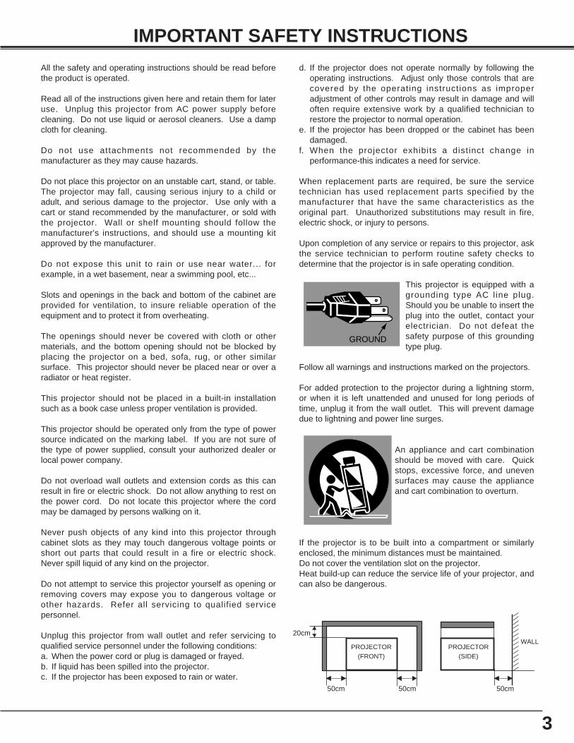
This projector is equipped with agrounding type AC line plug.Should you be unable to insert theplug into the outlet, contact yourelectrician. Do not defeat thesafety purpose of this groundingtype plug.
Follow all warnings and instructions marked on the projectors.
For added protection to the projector during a lightning storm,or when it is left unattended and unused for long periods oftime, unplug it from the wall outlet. This will prevent damagedue to lightning and power line surges.
An appliance and cart combinationshould be moved with care. Quickstops, excessive force, and unevensurfaces may cause the applianceand cart combination to overturn.
If the projector is to be built into a compartment or similarlyenclosed, the minimum distances must be maintained. Do not cover the ventilation slot on the projector. Heat build-up can reduce the service life of your projector, andcan also be dangerous.
GROUND
20cm
50cm 50cm 50cm
PROJECTOR(FRONT)
PROJECTOR(SIDE)
WALL
4
TABLE OF CONTENTS
TRADEMARKS● Apple, Macintosh, and PowerBook are trademarks or registered trademarks of Apple Computer,Inc.● IBM and PS/2 are trademarks or registered trademarks of International Business Machines, Inc.● Windows and PowerPoint are registered trademarks of Microsoft Corporation.● Each name of corporations or products in the owner's manual is a trademark or a registered trademark of its
respective corporation.
MCI MODE 32
OPERATING THE PC CARD SLOT 32SELECTING MCI MODE 33SHOW THE DATA IN THE MEMORY CARD 34WRITE DATA INTO THE MEMORY CARD 35PICTURE IMAGE ADJUSTMENT 36PICTURE POSITION ADJUSTMENT 36PICTURE SCREEN ADJUSTMENT 37CF CARD AND PCMCIA ADAPTER 38
FEATURES AND DESIGN 5
BEFORE OPERATION 14
PREPARATION 6
NAME OF EACH PART OF THE PROJECTOR 6SETTING-UP THE PROJECTOR 7
POSITIONING THE PROJECTOR 7ADJUSTABLE FEET 7CONNECTING THE AC POWER CORD 8VENTILATION 8MOUNTING LENS COVER 9MOVING THE PROJECTOR 9
CONNECTING THE PROJECTOR 10
TERMINALS OF THE PROJECTOR 10CONNECTING TO THE VIDEO EQUIPMENT 11CONNECTING TO THE COMPUTER 12
OPERATION OF THE REMOTE CONTROL 14LASER POINTER FUNCTION 14REMOTE CONTROL BATTERY INSTALLATION 15
TOP CONTROLS AND INDICATORS 16OPERATING ON-SCREEN MENU 17
HOW TO OPERATE THE ON-SCREEN MENU 17FLOW OF ON-SCREEN MENU 17MENU BAR 18
BASIC OPERATION 20
TURNING ON / OFF THE PROJECTOR 20ADJUSTING THE IMAGE 21
ZOOM ADJUSTMENT 21FOCUS ADJUSTMENT 21KEYSTONE ADJUSTMENT 21BRIGHT SWITCH 22NO SHOW FUNCTION 22PICTURE FREEZE FUNCTION 22
SOUND ADJUSTMENT 22SOUND VOLUME ADJUSTMENT 22SOUND MUTE ADJUSTMENT 22
COMPUTER MODE 23
VIDEO MODE 30
SETTING 40
APPENDIX 41
SELECTING COMPUTER MODE 23SELECTING COMPUTER SYSTEM 23PC ADJUSTMENT 24COMPATIBLE COMPUTER SPECIFICATION 26PICTURE IMAGE ADJUSTMENT 27PICTURE POSITION ADJUSTMENT 28PICTURE SCREEN ADJUSTMENT 29
SELECTING VIDEO MODE 30SELECTING COLOR SYSTEM 30PICTURE SCREEN ADJUSTMENT 30PICTURE IMAGE ADJUSTMENT 31
SETTING MENU 40SETTING LANGUAGE 40
OPERATING WIRELESS MOUSE 41MAINTENANCE 42
TEMPERATURE WARNING INDICATOR 42AIR FILTER CARE AND CLEANING 42CLEANING THE PROJECTION LENS 42LAMP REPLACEMENT 43LAMP REPLACEMENT MONITOR TIMER 43
TROUBLESHOOTING 44TECHNICAL SPECIFICATIONS 46
5
FEATURES AND DESIGN
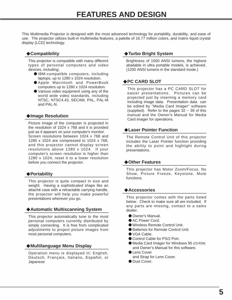
This Multimedia Projector is designed with the most advanced technology for portability, durability, and ease ofuse. The projector utilizes built-in multimedia features, a palette of 16.77 million colors, and matrix liquid crystaldisplay (LCD) technology.
◆ Compatibility
This projector is compatible with many differenttypes of personal computers and videodevices, including;
● IBM-compatible computers, includinglaptops, up to 1280 x 1024 resolution.
● Apple Macintosh and PowerBookcomputers up to 1280 x 1024 resolution.
● Various video equipment using any of theworld wide video standards, includingNTSC, NTSC4.43, SECAM, PAL, PAL-Mand PAL-N.
◆ Image Resolution
Picture Image of the computer is projected inthe resolution of 1024 x 768 and it is providedjust as it appears on your computer's monitor. Screen resolutions between 1024 x 768 and1280 x 1024 are compressed to 1024 x 768,and this projector cannot display screenresolutions above 1280 x 1024. If yourcomputer's screen resolution is higher than1280 x 1024, reset it to a lower resolutionbefore you connect the projector.
◆ Automatic Multiscanning System
This projector automatically tune to the mostpersonal computers currently distributed bysimply connecting. It is free from complicatedadjustments to project picture images frommost personal computers.
◆ Accessories
This projector comes with the parts listedbelow. Check to make sure all are included. Ifany parts are missing, contact to a salesdealer.
● Owner's Manual.● AC Power Cord.● Wireless Remote Control Unit.● Batteries for Remote Control Unit.● VGA Cable.● Control Cable for PS/2 Port.● Media Card Imager for Windows 95 (CD-ROM)
and Owner’s Manual for this software.● Lens Cover
and Strap for Lens Cover.● Dust Cover.
◆ Other Features
This projector has Motor Zoom/Focus, NoShow, Picture Freeze, Keystone, Mutefunctions.
◆ Portability
This projector is quite compact in size andweight. Having a sophisticated shape like anattaché case with a retractable carrying handle,the projector will help you make powerfulpresentations wherever you go.
◆ Multilanguage Menu Display
Operation menu is displayed in; English,Deutsch, Français, Ital iano, Español, orJapanese
◆ Laser Pointer Function
The Remote Control Unit of this projectorincludes the Laser Pointer function providingthe abil i ty to point and highlight duringpresentations.
◆ PC CARD SLOT
This projector has a PC CARD SLOT foreasier presentations. Pictures can beprojected just by inserting a memory cardincluding image data. Presentation data canbe edited by "Media Card Imager" software(supplied). Refer to the pages 32 ~ 39 of thismanual and the Owner's Manual for MediaCard imager for operations.
◆ Turbo Bright System
Brightness of 1500 ANSI lumens, the highestabailable in ultra portable models, is achieved.(1200 ANSI lumens in the standard mode.)
6
PREPARATION
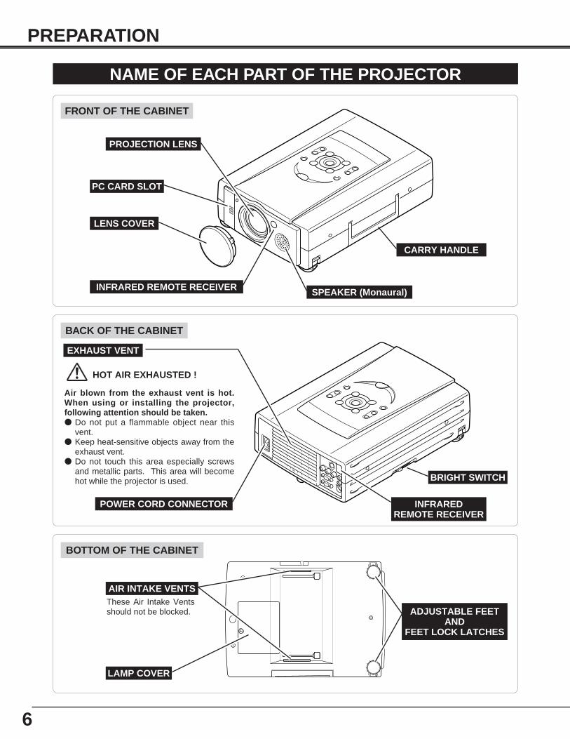
NAME OF EACH PART OF THE PROJECTOR
These Air Intake Ventsshould not be blocked.
BOTTOM OF THE CABINET
BACK OF THE CABINET
CARRY HANDLE
HOT AIR EXHAUSTED !
Air blown from the exhaust vent is hot.When using or installing the projector,following attention should be taken.● Do not put a flammable object near this
vent. ● Keep heat-sensitive objects away from the
exhaust vent.● Do not touch this area especially screws
and metallic parts. This area will becomehot while the projector is used.
INFRARED REMOTE RECEIVER
POWER CORD CONNECTOR
EXHAUST VENT
FRONT OF THE CABINET
LAMP COVER
ADJUSTABLE FEETAND
FEET LOCK LATCHES
PROJECTION LENS
SPEAKER (Monaural)INFRARED REMOTE RECEIVER
LENS COVER
AIR INTAKE VENTS
PC CARD SLOT
BRIGHT SWITCH
7
PREPARATION
ADJUSTABLE FEET
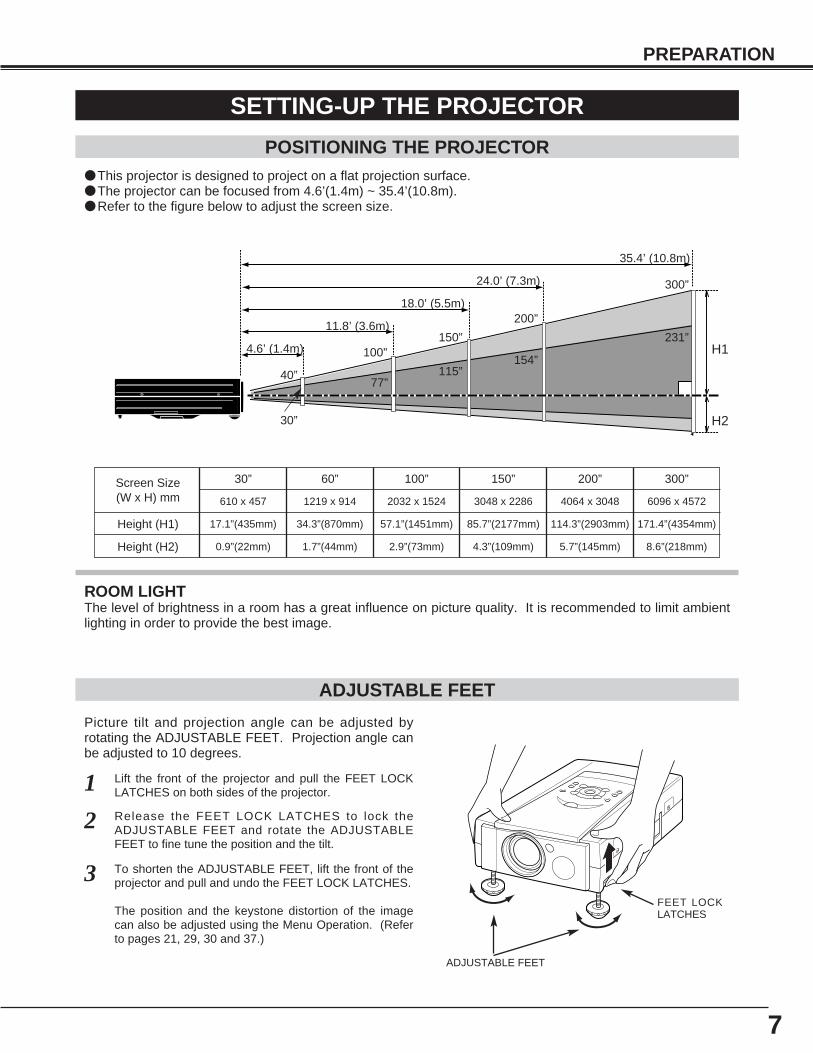
Picture tilt and projection angle can be adjusted byrotating the ADJUSTABLE FEET. Projection angle canbe adjusted to 10 degrees.
Lift the front of the projector and pull the FEET LOCKLATCHES on both sides of the projector.1
ADJUSTABLE FEET
SETTING-UP THE PROJECTOR
FEET LOCKLATCHES
Release the FEET LOCK LATCHES to lock theADJUSTABLE FEET and rotate the ADJUSTABLEFEET to fine tune the position and the tilt.
2
To shorten the ADJUSTABLE FEET, lift the front of theprojector and pull and undo the FEET LOCK LATCHES.
The position and the keystone distortion of the imagecan also be adjusted using the Menu Operation. (Referto pages 21, 29, 30 and 37.)
3
POSITIONING THE PROJECTOR● This projector is designed to project on a flat projection surface.● The projector can be focused from 4.6’(1.4m) ~ 35.4’(10.8m).● Refer to the figure below to adjust the screen size.
H1
H2
300”
231”
200”
154”
150”
115”
100”
77”40”
35.4’ (10.8m)
24.0’ (7.3m)
18.0’ (5.5m)
11.8’ (3.6m)
4.6’ (1.4m)
Screen Size(W x H) mm
Height (H1)
30”
Height (H2)
610 x 457
17.1”(435mm)
0.9”(22mm)
60”
1219 x 914
34.3”(870mm)
1.7”(44mm)
100”
2032 x 1524
57.1”(1451mm)
2.9”(73mm)
150”
3048 x 2286
85.7”(2177mm)
4.3”(109mm)
200”
4064 x 3048
114.3”(2903mm)
5.7”(145mm)
300”
6096 x 4572
171.4”(4354mm)
8.6”(218mm)
ROOM LIGHTThe level of brightness in a room has a great influence on picture quality. It is recommended to limit ambientlighting in order to provide the best image.
30”
8
PREPARATION
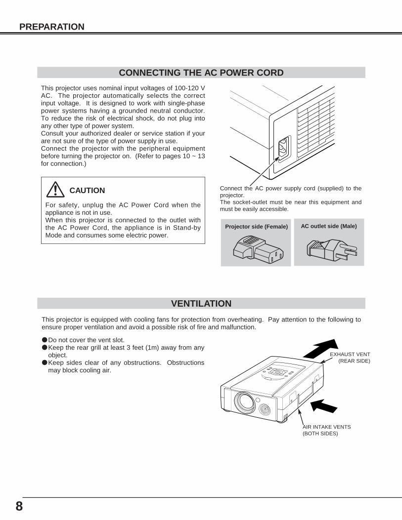
● Do not cover the vent slot.● Keep the rear grill at least 3 feet (1m) away from any
object.● Keep sides clear of any obstructions. Obstructions
may block cooling air.
This projector is equipped with cooling fans for protection from overheating. Pay attention to the following toensure proper ventilation and avoid a possible risk of fire and malfunction.
VENTILATION
AIR INTAKE VENTS (BOTH SIDES)
EXHAUST VENT(REAR SIDE)
This projector uses nominal input voltages of 100-120 VAC. The projector automatically selects the correctinput voltage. It is designed to work with single-phasepower systems having a grounded neutral conductor.To reduce the risk of electrical shock, do not plug intoany other type of power system.Consult your authorized dealer or service station if yourare not sure of the type of power supply in use.Connect the projector with the peripheral equipmentbefore turning the projector on. (Refer to pages 10 ~ 13for connection.)
CAUTION
For safety, unplug the AC Power Cord when theappliance is not in use.When this projector is connected to the outlet withthe AC Power Cord, the appliance is in Stand-byMode and consumes some electric power.
CONNECTING THE AC POWER CORD
Connect the AC power supply cord (supplied) to theprojector.The socket-outlet must be near this equipment andmust be easily accessible.
Projector side (Female) AC outlet side (Male)
9
PREPARATION
CAUTION IN CARRYING OR TRANSPORTING THE PROJECTOR
● Do not drop or bump the projector, otherwise damages or malfunctions may result.● When transporting the projector, use a carrying case recommended by Canon.● Do not transport the projector by using a courier or transport service in an unsuitable transport case. This
may cause damage to the projector. To transport the projector through a courier or transport service, usea case recommended by Canon.
● For carrying or transportation cases, contact a Canon authorized dealer.
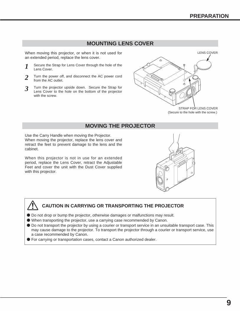
MOVING THE PROJECTOR
Use the Carry Handle when moving the Projector.When moving the projector, replace the lens cover andretract the feet to prevent damage to the lens and thecabinet.
When this projector is not in use for an extendedperiod, replace the Lens Cover, retract the AdjustableFeet and cover the unit with the Dust Cover suppliedwith this projector.
MOUNTING LENS COVER
When moving this projector, or when it is not used foran extended period, replace the lens cover.
Secure the Strap for Lens Cover through the hole of theLens Cover.1Turn the power off, and disconnect the AC power cordfrom the AC outlet. 2Turn the projector upside down. Secure the Strap forLens Cover to the hole on the bottom of the projectorwith the screw.
3
LENS COVER
STRAP FOR LENS COVER(Secure to the hole with the screw.)
10
CONNECTING THE PROJECTOR
TERMINALS OF THE PROJECTOR
S-VIDEO
R-AUDIO-L(MONO) VIDEOAUDIO
IN
OUT
CONTROL PORT
COMPUTER IN
MONITOR OUT
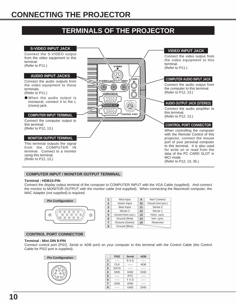
Connect the computer output tothis terminal. (Refer to P12, 13.)
When controlling the computerwith the Remote Control of thisprojector, connect the mouseport of your personal computerto this terminal. It is also usedfor write on or read from thedata of the PC CARD SLOT inMCI mode. (Refer to P12, 13, 35.)
This terminal outputs the signalfrom the COMPUTER INterminal. Connect to a monitorusing this terminal.(Refer to P12, 13.)
Connect the audio amplifier tothis terminal.(Refer to P12, 13.)
Connect the S-VIDEO outputfrom the video equipment to thisterminal.(Refer to P11.)
Connect the audio output fromthe computer to this terminal. (Refer to P12, 13.)
Connect the audio outputs fromthe video equipment to theseterminals.(Refer to P11.)● When the audio output is
monaural, connect it to the L(mono) jack.
COMPUTER INPUT TERMINAL
MONITOR OUTPUT TERMINAL
CONTROL PORT CONNECTOR
COMPUTER AUDIO INPUT JACKAUDIO INPUT JACKS
VIDEO INPUT JACKS-VIDEO INPUT JACK
AUDIO OUTPUT JACK (STEREO)
Connect the video output fromthe video equipment to thisterminal.(Refer to P11.)
COMPUTER INPUT / MONITOR OUTPUT TERMINAL
Terminal : HDB15-PIN Connect the display output terminal of the computer to COMPUTER INPUT with the VGA Cable (supplied). And connectthe monitor to MONITOR OUTPUT with the monitor cable (not supplied). When connecting the Macintosh computer, theMAC Adapter (not supplied) is required.
5 123410 9 678
15 14 13 1112
Red Input
Ground (Horiz.sync.)
Green Input
Sense 2Blue Input
Ground (Red)Ground (Green)Ground (Blue)
1
5
2
43
678
Non Connect
Horiz. sync.
Ground (Vert.sync.)
Sense 1Sense 0
Vert. sync.Reserved
9
13
10
1211
1415
Pin Configuration
Terminal : Mini DIN 8-PINConnect control port (PS/2, Serial or ADB port) on your computer to this terminal with the Control Cable (the ControlCable for PS/2 port is supplied).
12
3458 7 6
Pin Configuration
CONTROL PORT CONNECTOR
-----CLK
DATAGND----------
GND-----
R X D----------
GNDRTST X DGNDGND
-----ADB-----
GND---------------
GND
PS/2 Serial ADB
12345678
S-VIDEO
R-AUDIO-L(MONO) VIDEOAUDIO
IN
OUT
CONTROL PORT
COMPUTER IN
MONITOR OUT
11
CONNECTING THE PROJECTOR
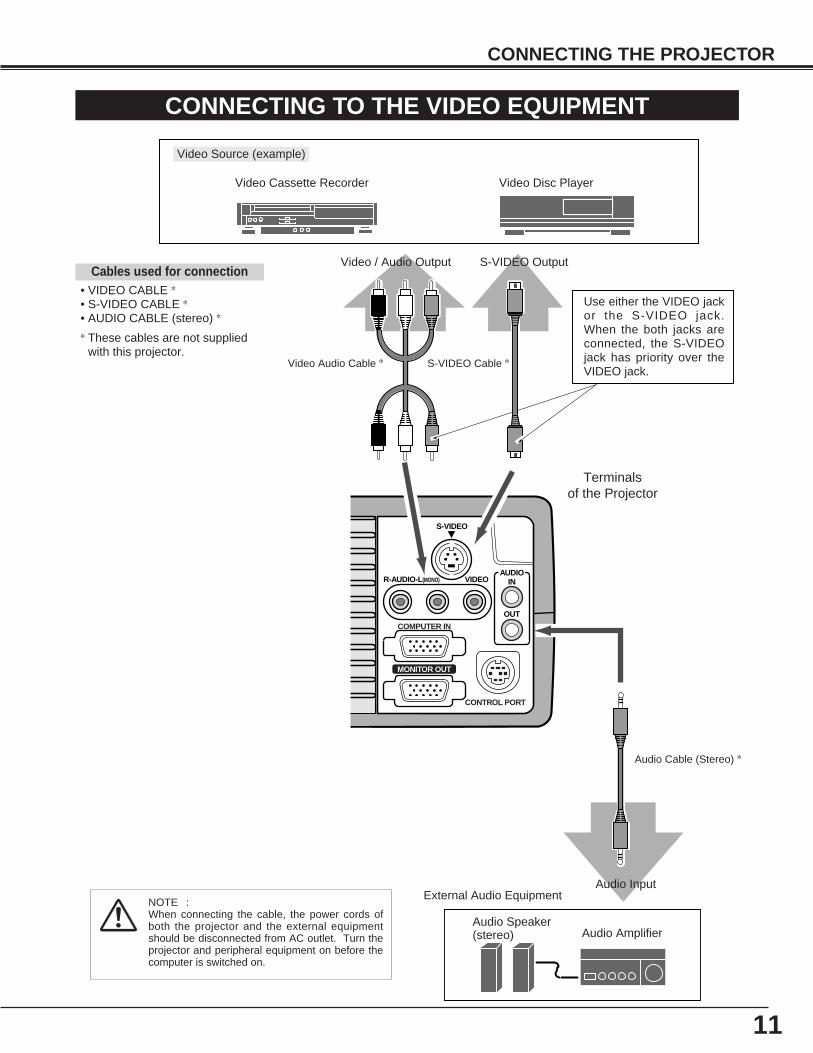
CONNECTING TO THE VIDEO EQUIPMENT
Video Source (example)
Video Cassette Recorder Video Disc Player
Video Audio Cable ✽ S-VIDEO Cable ✽
Audio AmplifierAudio Speaker(stereo)
External Audio Equipment
Audio Cable (Stereo) ✽
Terminals of the Projector
Use either the VIDEO jackor the S-VIDEO jack.When the both jacks areconnected, the S-VIDEOjack has priority over theVIDEO jack.
Video / Audio Output S-VIDEO Output
Audio Input
• VIDEO CABLE ✽
• S-VIDEO CABLE ✽
• AUDIO CABLE (stereo) ✽
✽ These cables are not suppliedwith this projector.
Cables used for connection
NOTE :When connecting the cable, the power cords ofboth the projector and the external equipmentshould be disconnected from AC outlet. Turn theprojector and peripheral equipment on before thecomputer is switched on.
12
CONNECTING THE PROJECTOR
ON
1 2 3 4 5 6
DIP
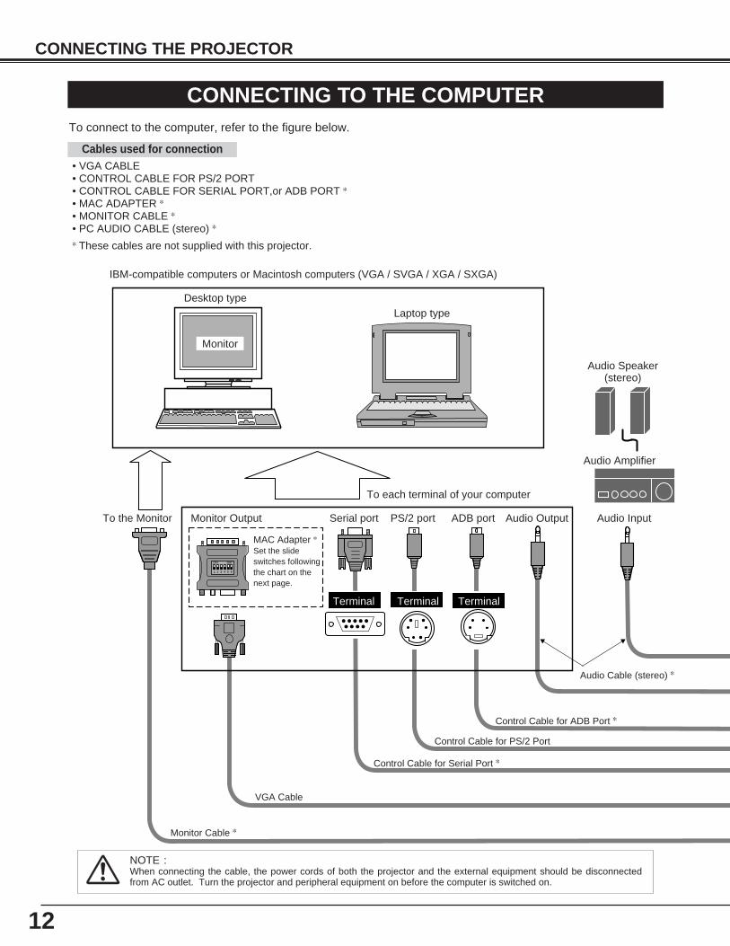
CONNECTING TO THE COMPUTERTo connect to the computer, refer to the figure below.
IBM-compatible computers or Macintosh computers (VGA / SVGA / XGA / SXGA)
VGA Cable
Monitor Output
Desktop typeLaptop type
Monitor
Audio Speaker(stereo)
Audio Amplifier
Control Cable for Serial Port ✽
Control Cable for PS/2 Port
Audio Cable (stereo) ✽
Monitor Cable ✽
Terminal Terminal
Serial port PS/2 port Audio Output Audio Input
To each terminal of your computer
To the Monitor
NOTE :When connecting the cable, the power cords of both the projector and the external equipment should be disconnectedfrom AC outlet. Turn the projector and peripheral equipment on before the computer is switched on.
MAC Adapter ✽
Set the slideswitches followingthe chart on thenext page.
Terminal
ADB port
Control Cable for ADB Port ✽
• VGA CABLE • CONTROL CABLE FOR PS/2 PORT • CONTROL CABLE FOR SERIAL PORT,or ADB PORT ✽
• MAC ADAPTER ✽
• MONITOR CABLE ✽
• PC AUDIO CABLE (stereo) ✽
✽ These cables are not supplied with this projector.
Cables used for connection
13
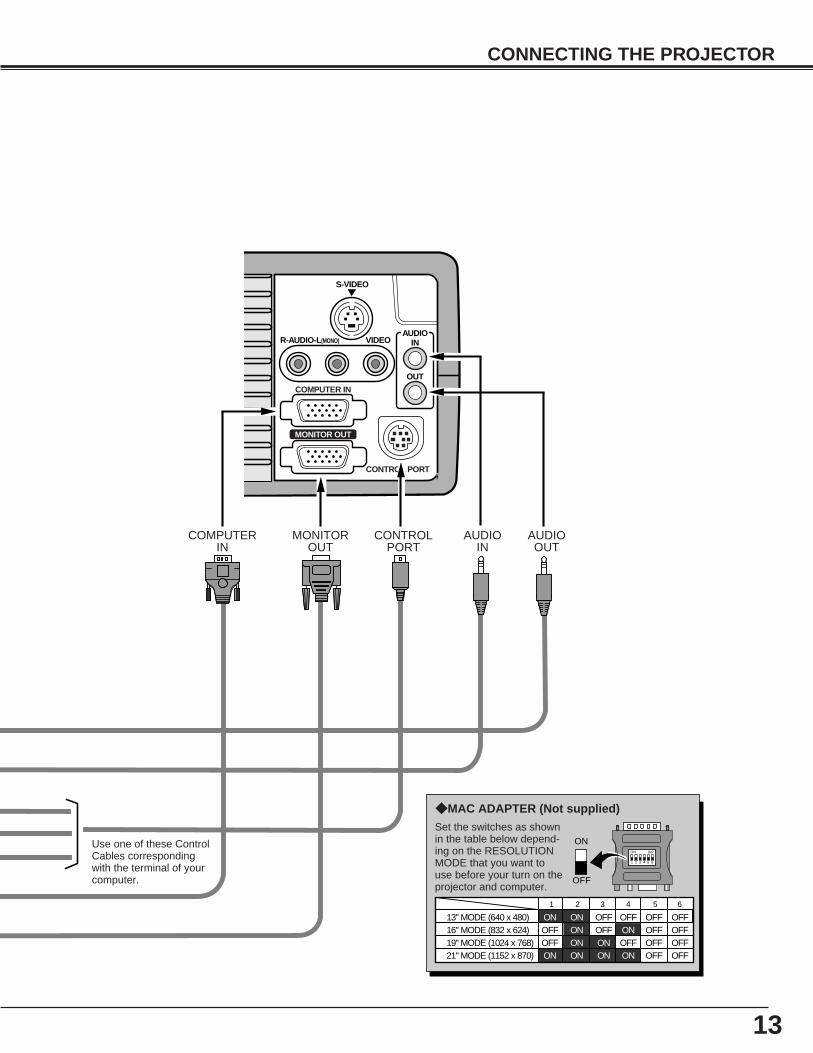
CONNECTING THE PROJECTOR
S-VIDEO
R-AUDIO-L(MONO) VIDEOAUDIO
IN
OUT
CONTROL PORT
COMPUTER IN
MONITOR OUT
ON
1
DIP
ON
OFF
2 3 4 5 6
13" MODE (640 x 480)16" MODE (832 x 624)19" MODE (1024 x 768)
OFFON ONON ONON ON
OFF OFF OFFOFFOFF OFF OFF
OFF OFF OFF OFF
1 2 3 4 5 6
OFF OFFON ONON ON21" MODE (1152 x 870)
CONTROLPORT
AUDIOOUT
AUDIOIN
MONITOROUT
COMPUTERIN
Use one of these ControlCables correspondingwith the terminal of yourcomputer.
Set the switches as shownin the table below depend-ing on the RESOLUTIONMODE that you want touse before your turn on theprojector and computer.
◆ MAC ADAPTER (Not supplied)
14
BEFORE OPERATION
OPERATION OF THE REMOTE CONTROL
VOLUME
POWER
FOCUSZOOM
VIDEOCOMPUTER/
MCI
D.ZOOM
MENU
MUTE
LASER
KEYSTONENO SHOW FREEZE
AUTO IMAGE NORMAL
PAGE
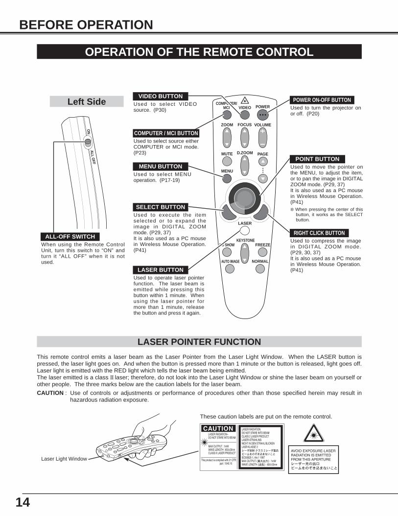
Used to select source eitherCOMPUTER or MCI mode.(P23)
Used to select VIDEOsource. (P30)
Used to execute the itemselected or to expand theimage in DIGITAL ZOOMmode. (P29, 37)It is also used as a PC mousein Wireless Mouse Operation.(P41)
POWER ON-OFF BUTTONUsed to turn the projector onor off. (P20)
MENU BUTTONUsed to select MENUoperation. (P17-19)
SELECT BUTTON
ON
ALL O
FF
ALL-OFF SWITCHWhen using the Remote ControlUnit, turn this switch to “ON” andturn it “ALL OFF” when it is notused.
Used to move the pointer onthe MENU, to adjust the item,or to pan the image in DIGITALZOOM mode. (P29, 37) It is also used as a PC mousein Wireless Mouse Operation.(P41)✽ When pressing the center of this
button, it works as the SELECTbutton.
VIDEO BUTTON
COMPUTER / MCI BUTTON
POINT BUTTON
LASER BUTTONUsed to operate laser pointerfunction. The laser beam isemitted while pressing thisbutton within 1 minute. Whenusing the laser pointer formore than 1 minute, releasethe button and press it again.
This remote control emits a laser beam as the Laser Pointer from the Laser Light Window. When the LASER button ispressed, the laser light goes on. And when the button is pressed more than 1 minute or the button is released, light goes off.Laser light is emitted with the RED light which tells the laser beam being emitted.The laser emitted is a class II laser; therefore, do not look into the Laser Light Window or shine the laser beam on yourself orother people. The three marks below are the caution labels for the laser beam.
CAUTION : Use of controls or adjustments or performance of procedures other than those specified herein may result inhazardous radiation exposure.
Laser Light Window
These caution labels are put on the remote control.
Used to compress the imagein DIGITAL ZOOM mode.(P29, 30, 37) It is also used as a PC mousein Wireless Mouse Operation.(P41)
RIGHT CLICK BUTTON
LASER POINTER FUNCTION
Left Side
15
BEFORE OPERATION
VOLUME
POWER
FOCUSZOOM
VIDEOCOMPUTER/
MCI
D.ZOOM
MENU
MUTE
LASER
KEYSTONENO SHOW FREEZE
AUTO IMAGE NORMAL
PAGE
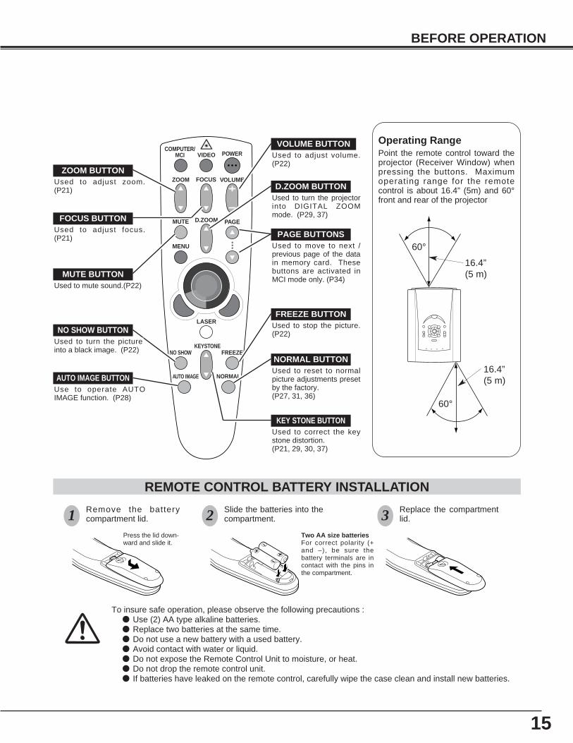
To insure safe operation, please observe the following precautions :● Use (2) AA type alkaline batteries.● Replace two batteries at the same time.● Do not use a new battery with a used battery.● Avoid contact with water or liquid.● Do not expose the Remote Control Unit to moisture, or heat.● Do not drop the remote control unit.● If batteries have leaked on the remote control, carefully wipe the case clean and install new batteries.
Press the lid down-ward and slide it.
Remove the batterycompartment lid.
Slide the batteries into thecompartment.
Replace the compartmentlid.
Two AA size batteriesFor correct polarity (+and –), be sure thebattery terminals are incontact with the pins inthe compartment.
REMOTE CONTROL BATTERY INSTALLATION
1 2 3
MUTE BUTTONUsed to mute sound.(P22)
ZOOM BUTTONUsed to adjust zoom.(P21)
FOCUS BUTTONUsed to adjust focus.(P21)
NO SHOW BUTTONUsed to turn the pictureinto a black image. (P22)
AUTO IMAGE BUTTONUse to operate AUTOIMAGE function. (P28)
VOLUME BUTTONUsed to adjust volume.(P22)
D.ZOOM BUTTONUsed to turn the projectorinto DIGITAL ZOOMmode. (P29, 37)
KEY STONE BUTTONUsed to correct the keystone distortion.(P21, 29, 30, 37)
FREEZE BUTTONUsed to stop the picture.(P22)
NORMAL BUTTONUsed to reset to normalpicture adjustments presetby the factory. (P27, 31, 36)
Operating Range Point the remote control toward theprojector (Receiver Window) whenpressing the buttons. Maximumoperating range for the remotecontrol is about 16.4” (5m) and 60°front and rear of the projector
16.4”(5 m)
60°
60°
16.4”(5 m)
Used to move to next /previous page of the datain memory card. Thesebuttons are activated inMCI mode only. (P34)
PAGE BUTTONS
POWER
NORMAL MENU MODE AUTO IMAGE
FOCUSZOOM
VOLUME PAGE
LAMPREPLACE
WARNINGTEMP. READY LAMP
WIDE
TELE
SELECT
BRIGHT
16
BEFORE OPERATION
TOP CONTROLS AND INDICATORS
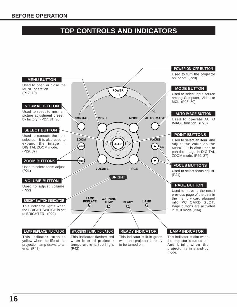
Used to open or close theMENU operation. (P17, 19)
MENU BUTTON
AUTO IMAGE BUTTON
READY INDICATOR
POWER ON–OFF BUTTON
WARNING TEMP. INDICATOR LAMP INDICATORLAMP REPLACE INDICATOR
Used to operate AUTOIMAGE function. (P28)
This indicator is lit in greenwhen the projector is readyto be turned on.
This indicator is dim whenthe projector is turned on.And bright when theprojector is in stand-bymode.
This indicator turns toyellow when the life of theprojection lamp draws to anend. (P43)
This indicator flashes redwhen internal projectortemperature is too high.(P42)
Used to turn the projectoron or off. (P20)
Used to select zoom adjust.(P21)
MODE BUTTON
SELECT BUTTON
FOCUS BUTTONS
NORMAL BUTTON
VOLUME BUTTON
POINT BUTTONS
Used to select input sourceamong Computer, Video orMCI. (P23, 30)
Used to select focus adjust.(P21)
Used to adjust volume.(P22)
Used to reset to normalpicture adjustment presetby factory. (P27, 31, 36)
Used to select an item andadjust the value on theMENU. It is also used topan the image in DIGITALZOOM mode. (P29, 37)
Used to execute the itemselected. It is also used toexpand the image inDIGITAL ZOOM mode. (P29, 37)
ZOOM BUTTONS
PAGE BUTTONUsed to move to the next /previous page of the data inthe memory card pluggedinto PC CARD SLOT.Page buttons are activatedin MCI mode (P34).
BRIGHT SWITCH INDICATORThis indicator lights whenthe BRIGHT SWITCH is setto BRIGHTER. (P22)
17
SELECT
BEFORE OPERATION
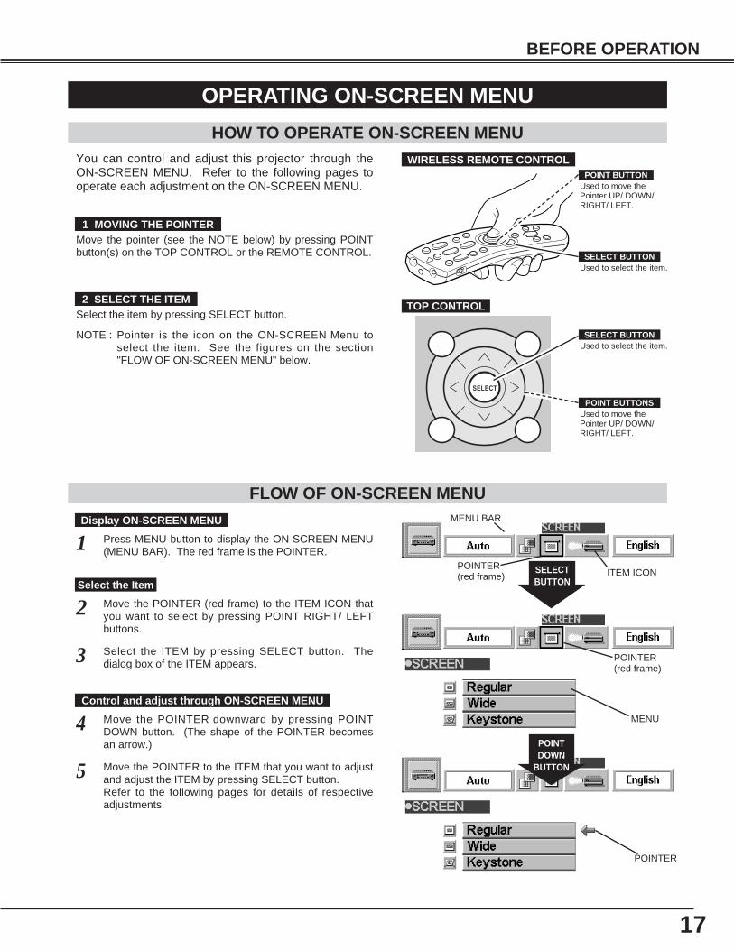
HOW TO OPERATE ON-SCREEN MENU
FLOW OF ON-SCREEN MENU
Display ON-SCREEN MENU
Press MENU button to display the ON-SCREEN MENU(MENU BAR). The red frame is the POINTER.
Select the ITEM by pressing SELECT button. Thedialog box of the ITEM appears.
Move the POINTER (red frame) to the ITEM ICON thatyou want to select by pressing POINT RIGHT/ LEFTbuttons.
Move the POINTER to the ITEM that you want to adjustand adjust the ITEM by pressing SELECT button.Refer to the following pages for details of respectiveadjustments.
Move the POINTER downward by pressing POINTDOWN button. (The shape of the POINTER becomesan arrow.)
Select the Item
Control and adjust through ON-SCREEN MENU
1
2
3
5
4
You can control and adjust this projector through theON-SCREEN MENU. Refer to the following pages tooperate each adjustment on the ON-SCREEN MENU.
1 MOVING THE POINTER
2 SELECT THE ITEM
Move the pointer (see the NOTE below) by pressing POINTbutton(s) on the TOP CONTROL or the REMOTE CONTROL.
Select the item by pressing SELECT button.
SELECTBUTTON
POINTDOWN
BUTTON
MENU BAR
POINTER(red frame) ITEM ICON
POINTER(red frame)
MENU
POINTER
Used to select the item.SELECT BUTTON
Used to move thePointer UP/ DOWN/RIGHT/ LEFT.
POINT BUTTONS
Used to select the item.SELECT BUTTON
Used to move thePointer UP/ DOWN/RIGHT/ LEFT.
POINT BUTTON
WIRELESS REMOTE CONTROL
TOP CONTROL
OPERATING ON-SCREEN MENU
NOTE : Pointer is the icon on the ON-SCREEN Menu toselect the item. See the figures on the section"FLOW OF ON-SCREEN MENU" below.
18
BEFORE OPERATION
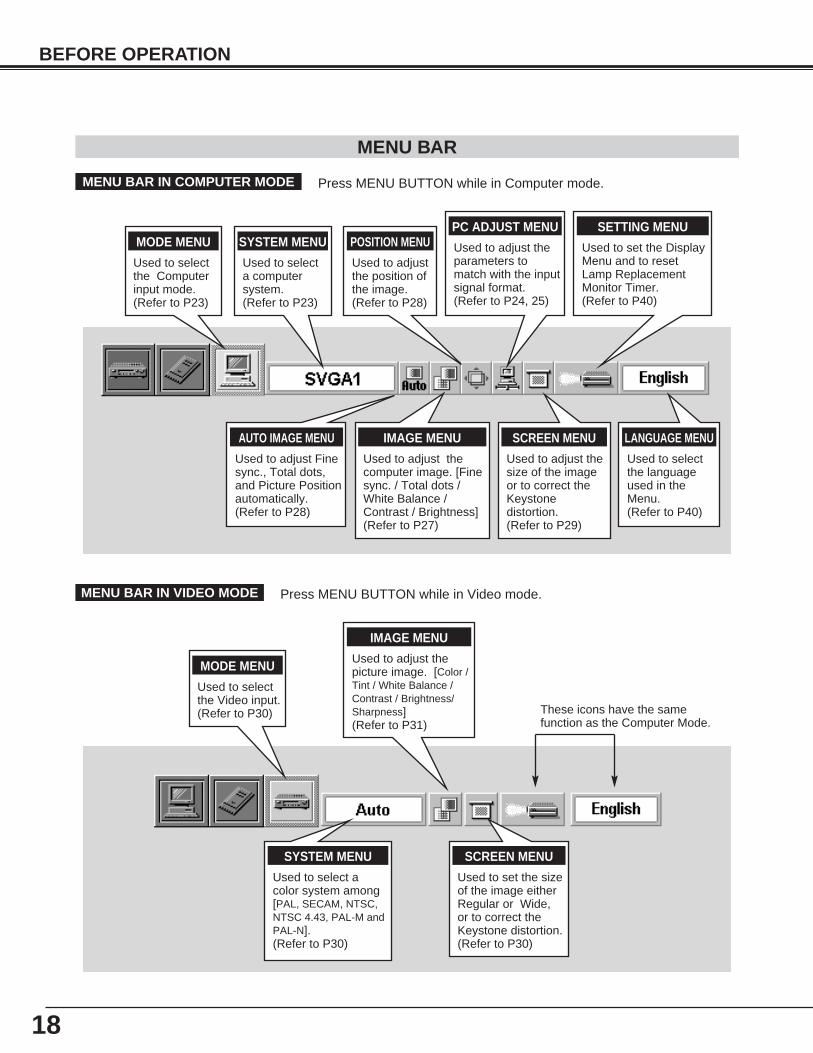
MENU BAR
IMAGE MENU
Used to adjust thecomputer image. [Finesync. / Total dots /White Balance /Contrast / Brightness](Refer to P27)
PC ADJUST MENU
Used to adjust theparameters tomatch with the inputsignal format.(Refer to P24, 25)
SETTING MENU
Used to set the DisplayMenu and to resetLamp ReplacementMonitor Timer.(Refer to P40)
MODE MENU
Used to selectthe Computerinput mode.(Refer to P23)
SCREEN MENU
Used to adjust thesize of the imageor to correct theKeystonedistortion.(Refer to P29)
MENU BAR IN COMPUTER MODE Press MENU BUTTON while in Computer mode.
SYSTEM MENU
Used to select acolor system among[PAL, SECAM, NTSC,NTSC 4.43, PAL-M andPAL-N]. (Refer to P30)
IMAGE MENU
Used to adjust thepicture image. [Color /Tint / White Balance /Contrast / Brightness/Sharpness](Refer to P31)
SCREEN MENU
Used to set the sizeof the image eitherRegular or Wide,or to correct theKeystone distortion.(Refer to P30)
MENU BAR IN VIDEO MODE Press MENU BUTTON while in Video mode.
These icons have the samefunction as the Computer Mode.
LANGUAGE MENU
Used to selectthe languageused in theMenu. (Refer to P40)
MODE MENU
Used to selectthe Video input.(Refer to P30)
POSITION MENU
Used to adjustthe position ofthe image.(Refer to P28)
AUTO IMAGE MENU
Used to adjust Finesync., Total dots,and Picture Positionautomatically.(Refer to P28)
SYSTEM MENU
Used to selecta computersystem.(Refer to P23)
19
BASIC OPERATION
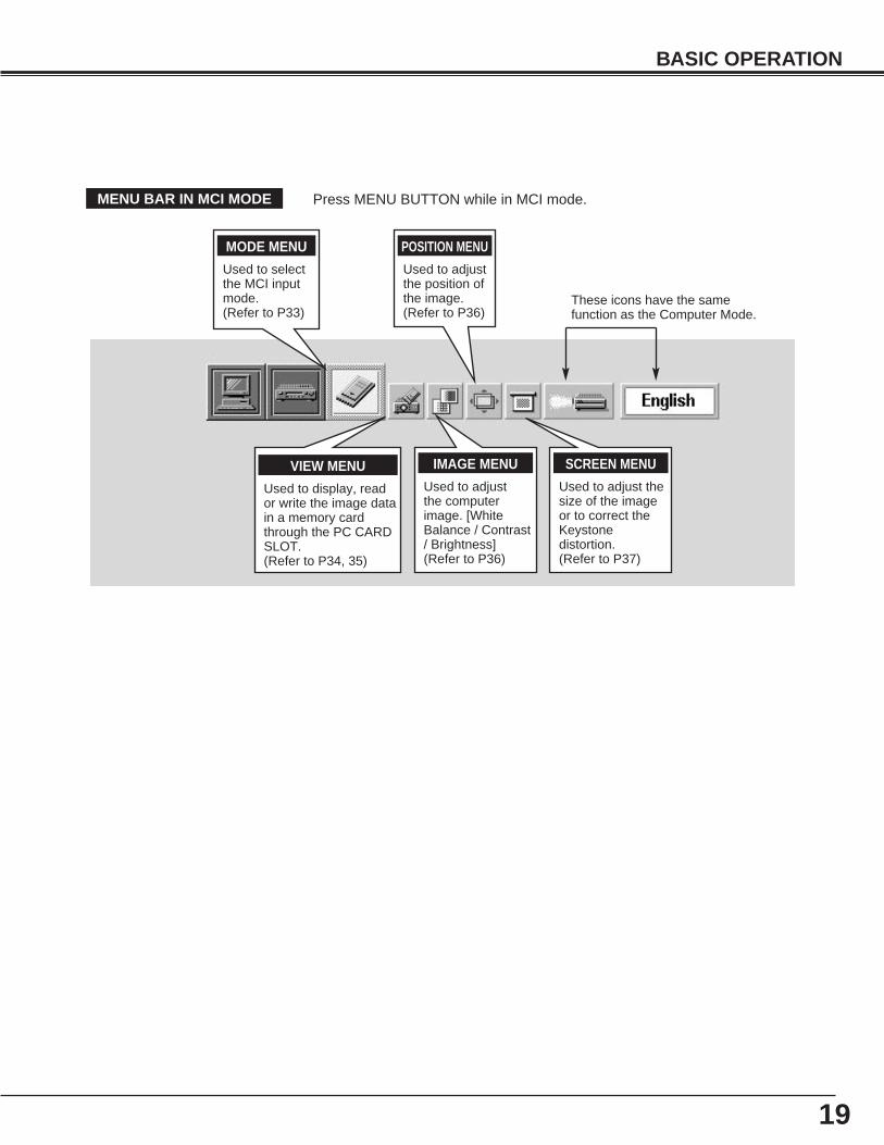
VIEW MENU
Used to display, reador write the image datain a memory cardthrough the PC CARDSLOT.(Refer to P34, 35)
MODE MENU
Used to selectthe MCI inputmode.(Refer to P33)
MENU BAR IN MCI MODE Press MENU BUTTON while in MCI mode.
These icons have the samefunction as the Computer Mode.
IMAGE MENU
Used to adjustthe computerimage. [WhiteBalance / Contrast/ Brightness](Refer to P36)
POSITION MENU
Used to adjustthe position ofthe image.(Refer to P36)
SCREEN MENU
Used to adjust thesize of the imageor to correct theKeystonedistortion.(Refer to P37)
20
BASIC OPERATIONS
TURNING ON THE PROJECTOR
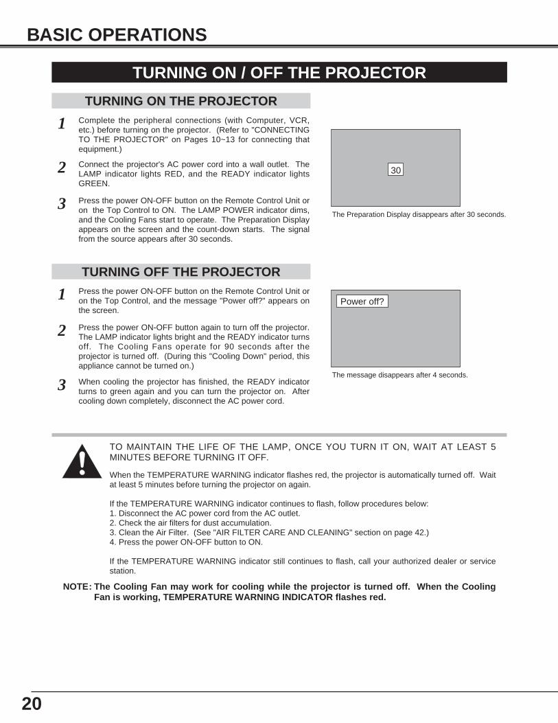
Connect the projector's AC power cord into a wall outlet. TheLAMP indicator lights RED, and the READY indicator lightsGREEN.
Press the power ON-OFF button on the Remote Control Unit oron the Top Control to ON. The LAMP POWER indicator dims,and the Cooling Fans start to operate. The Preparation Displayappears on the screen and the count-down starts. The signalfrom the source appears after 30 seconds.
2
3
TURNING OFF THE PROJECTORPress the power ON-OFF button on the Remote Control Unit oron the Top Control, and the message "Power off?" appears onthe screen.
Press the power ON-OFF button again to turn off the projector.The LAMP indicator lights bright and the READY indicator turnsoff. The Cooling Fans operate for 90 seconds after theprojector is turned off. (During this "Cooling Down" period, thisappliance cannot be turned on.)
1
2
TO MAINTAIN THE LIFE OF THE LAMP, ONCE YOU TURN IT ON, WAIT AT LEAST 5MINUTES BEFORE TURNING IT OFF.
Power off?
The message disappears after 4 seconds.
TURNING ON / OFF THE PROJECTOR
When the TEMPERATURE WARNING indicator flashes red, the projector is automatically turned off. Waitat least 5 minutes before turning the projector on again.
If the TEMPERATURE WARNING indicator continues to flash, follow procedures below:1. Disconnect the AC power cord from the AC outlet.2. Check the air filters for dust accumulation.3. Clean the Air Filter. (See "AIR FILTER CARE AND CLEANING" section on page 42.)4. Press the power ON-OFF button to ON.
If the TEMPERATURE WARNING indicator still continues to flash, call your authorized dealer or servicestation.
1 Complete the peripheral connections (with Computer, VCR,etc.) before turning on the projector. (Refer to "CONNECTINGTO THE PROJECTOR" on Pages 10~13 for connecting thatequipment.)
3 When cooling the projector has finished, the READY indicatorturns to green again and you can turn the projector on. Aftercooling down completely, disconnect the AC power cord.
30
The Preparation Display disappears after 30 seconds.
NOTE: The Cooling Fan may work for cooling while the projector is turned off. When the CoolingFan is working, TEMPERATURE WARNING INDICATOR flashes red.
21
BASIC OPERATION
ADJUSTING THE IMAGE
The message disappears after 4 seconds.
The message disappears after 4 seconds.
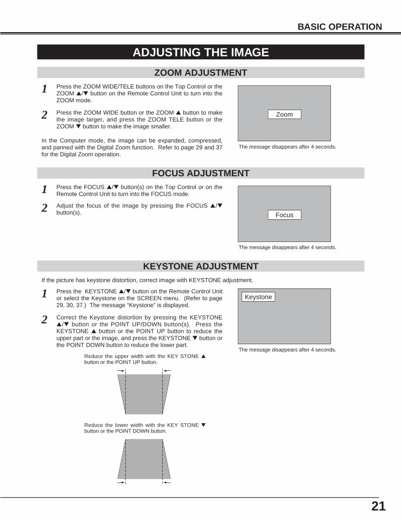
ZOOM ADJUSTMENT
1 Press the ZOOM WIDE/TELE buttons on the Top Control or theZOOM ▲/▼ button on the Remote Control Unit to turn into theZOOM mode.
2 Press the ZOOM WIDE button or the ZOOM ▲ button to makethe image larger, and press the ZOOM TELE button or theZOOM ▼ button to make the image smaller.
FOCUS ADJUSTMENT
1 Press the FOCUS ▲/▼ button(s) on the Top Control or on theRemote Control Unit to turn into the FOCUS mode.
2 Adjust the focus of the image by pressing the FOCUS ▲/▼button(s).
KEYSTONE ADJUSTMENT
1 Press the KEYSTONE ▲/▼ button on the Remote Control Unitor select the Keystone on the SCREEN menu. (Refer to page29, 30, 37.) The message “Keystone” is displayed.
2 Correct the Keystone distortion by pressing the KEYSTONE▲/▼ button or the POINT UP/DOWN button(s). Press theKEYSTONE ▲ button or the POINT UP button to reduce theupper part or the image, and press the KEYSTONE ▼ button orthe POINT DOWN button to reduce the lower part.
The message disappears after 4 seconds.Reduce the upper width with the KEY STONE ▲button or the POINT UP button.
Reduce the lower width with the KEY STONE ▼button or the POINT DOWN button.
In the Computer mode, the image can be expanded, compressed,and panned with the Digital Zoom function. Refer to page 29 and 37for the Digital Zoom operation.
Zoom
Focus
Keystone
If the picture has keystone distortion, correct image with KEYSTONE adjustment.
22
BASIC OPERATION
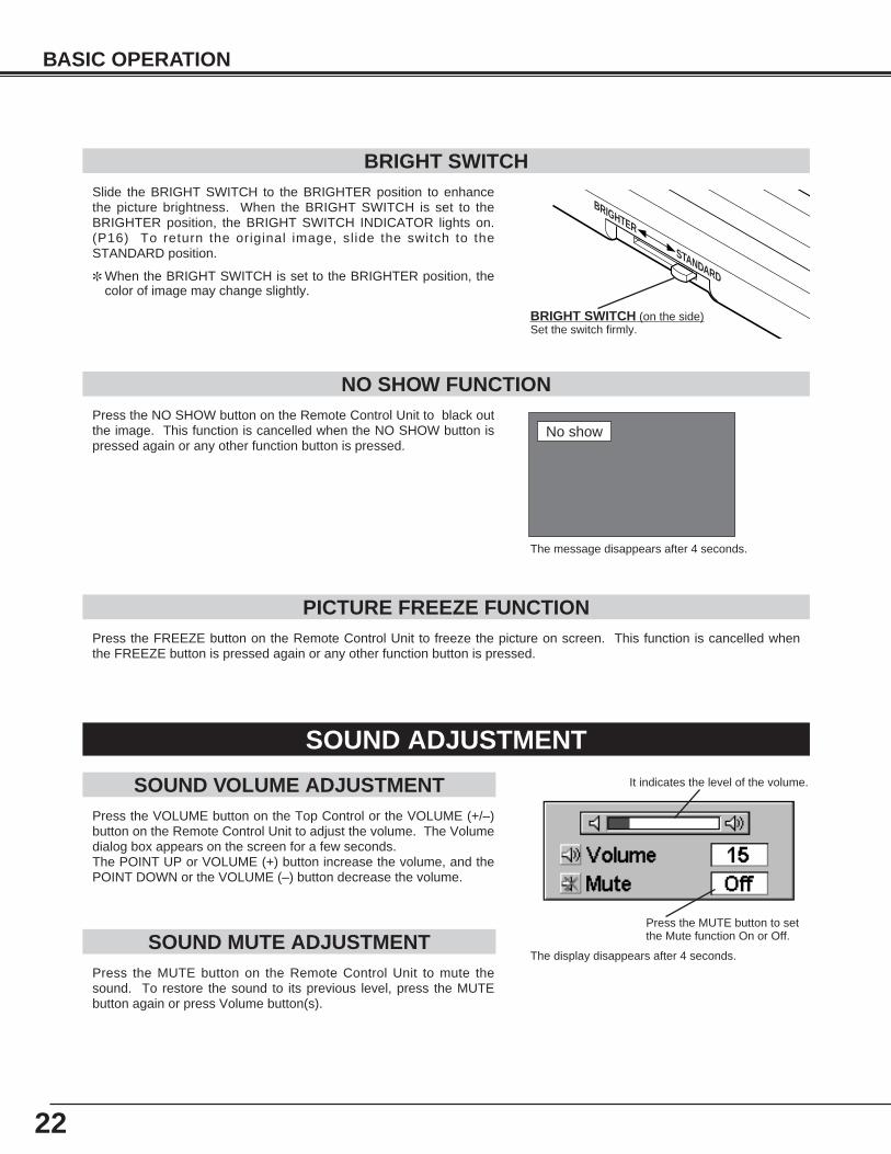
It indicates the level of the volume.
Press the MUTE button to setthe Mute function On or Off.
The display disappears after 4 seconds.
The message disappears after 4 seconds.
No show
Slide the BRIGHT SWITCH to the BRIGHTER position to enhancethe picture brightness. When the BRIGHT SWITCH is set to theBRIGHTER position, the BRIGHT SWITCH INDICATOR lights on.(P16) To return the original image, slide the switch to theSTANDARD position.
✽ When the BRIGHT SWITCH is set to the BRIGHTER position, thecolor of image may change slightly.
BRIGHT SWITCH
BRIGHTER
STANDARD
BRIGHT SWITCH (on the side)Set the switch firmly.
Press the VOLUME button on the Top Control or the VOLUME (+/–)button on the Remote Control Unit to adjust the volume. The Volumedialog box appears on the screen for a few seconds.The POINT UP or VOLUME (+) button increase the volume, and thePOINT DOWN or the VOLUME (–) button decrease the volume.
Press the MUTE button on the Remote Control Unit to mute thesound. To restore the sound to its previous level, press the MUTEbutton again or press Volume button(s).
SOUND ADJUSTMENT
Press the FREEZE button on the Remote Control Unit to freeze the picture on screen. This function is cancelled whenthe FREEZE button is pressed again or any other function button is pressed.
Press the NO SHOW button on the Remote Control Unit to black outthe image. This function is cancelled when the NO SHOW button ispressed again or any other function button is pressed.
NO SHOW FUNCTION
PICTURE FREEZE FUNCTION
SOUND MUTE ADJUSTMENT
SOUND VOLUME ADJUSTMENT
23
COMPUTER / MCIbutton
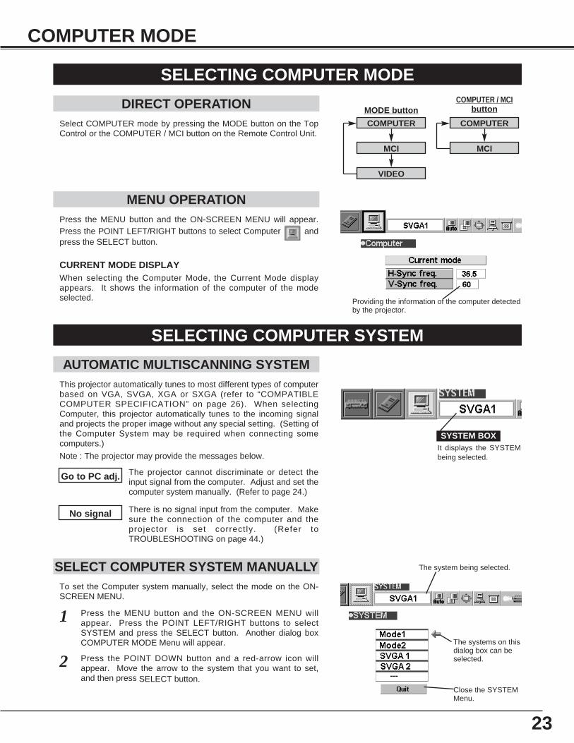
Press the MENU button and the ON-SCREEN MENU will appear.Press the POINT LEFT/RIGHT buttons to select Computer andpress the SELECT button.
COMPUTER MODE
SELECTING COMPUTER MODE
DIRECT OPERATIONSelect COMPUTER mode by pressing the MODE button on the TopControl or the COMPUTER / MCI button on the Remote Control Unit.
MENU OPERATION
When selecting the Computer Mode, the Current Mode displayappears. It shows the information of the computer of the modeselected.
CURRENT MODE DISPLAY
Providing the information of the computer detectedby the projector.
SELECTING COMPUTER SYSTEM
AUTOMATIC MULTISCANNING SYSTEMThis projector automatically tunes to most different types of computerbased on VGA, SVGA, XGA or SXGA (refer to “COMPATIBLECOMPUTER SPECIFICATION” on page 26). When selectingComputer, this projector automatically tunes to the incoming signaland projects the proper image without any special setting. (Setting ofthe Computer System may be required when connecting somecomputers.)
Note : The projector may provide the messages below.
The projector cannot discriminate or detect theinput signal from the computer. Adjust and set thecomputer system manually. (Refer to page 24.)
There is no signal input from the computer. Makesure the connection of the computer and theprojector is set correctly. (Refer toTROUBLESHOOTING on page 44.)
Go to PC adj.
No signal
SELECT COMPUTER SYSTEM MANUALLYTo set the Computer system manually, select the mode on the ON-SCREEN MENU.
It displays the SYSTEMbeing selected.
SYSTEM BOX
The system being selected.
The systems on thisdialog box can beselected.
Close the SYSTEMMenu.
Press the MENU button and the ON-SCREEN MENU willappear. Press the POINT LEFT/RIGHT buttons to selectSYSTEM and press the SELECT button. Another dialog boxCOMPUTER MODE Menu will appear.
Press the POINT DOWN button and a red-arrow icon willappear. Move the arrow to the system that you want to set,and then press SELECT button.
1
2
COMPUTER
MCI
VIDEO
COMPUTER
MCI
MODE button
24
COMPUTER MODE
PC ADJUSTMENTThis Projector can automatically tune to the display signals from most personal computers currently distributed.However, some computers employ the special signal formats which are different from the standard ones andmay not be tuned by Multiscanning of this projector. If this happens, the projector cannot reproduce a properimage and the image is recognized as a flickering picture, a non-synchronized picture, a non-centered picture ora skewed picture.This projector has PC ADJUSTMENT function, to enable you to precisely adjust several parameters to matchwith those exceptional signal formats and the projector has five independent memory areas to memorize thoseparameters manually adjusted. This enables you to recall the setting for a specific computer whenever you useit. Note : This PC ADJUSTMENT function cannot be operated when “RGB,” “HDTV1035i” or “HDTV1080i” is selected on the
SYSTEM MENU (P23 and 26).
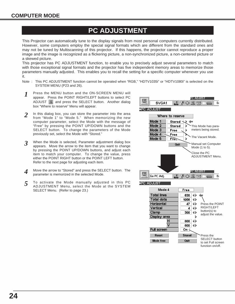
Press the MENU button and the ON-SCREEN MENU willappear. Press the POINT RIGHT/LEFT buttons to select PCADJUST and press the SELECT button. Another dialogbox “Where to reserve” Menu will appear.
In this dialog box, you can store the parameter into the areafrom “Mode 1” to “Mode 5.” When memorizing the newcomputer parameter, select the Mode with the message of“Free” by pressing the POINT UP/DOWN buttons and theSELECT button. To change the parameters of the Modepreviously set, select the Mode with “Stored.”
1
2
When the Mode is selected, Parameter adjustment dialog boxappears. Move the arrow to the item that you want to changeby pressing the POINT UP/DOWN buttons, and adjust eachitem to match your computer. To change the value, presseither the POINT RIGHT button or the POINT LEFT button.Refer to the next page for adjusting each item.
3
Move the arrow to “Stored” and press the SELECT button. Theparameter is memorized in the selected Mode.4
This Mode has para-meters being stored.
Close the PCADJUSTMENT Menu.
The Vacant Mode.
Manual set ComputerMode (1 to 5).
Press the POINTRIGHT/LEFTbutton(s) toadjust the value.
Press theSELECT buttonto set Full screenfunction on/off.
To activate the Mode manually adjusted in this PCADJUSTMENT Menu, select the Mode at the SYSTEMSELECT Menu. (Refer to page 23.)
5
25
COMPUTER MODE
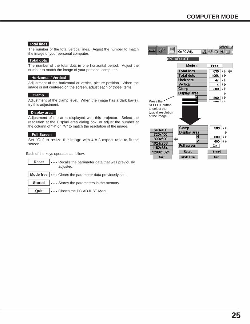
The number of the total vertical lines. Adjust the number to matchthe image of your personal computer.
Total lines
Recalls the parameter data that was previouslyadjusted.
Reset
Stores the parameters in the memory.Stored
Clears the parameter data previously set .Mode free
Closes the PC ADJUST Menu.Quit
The number of the total dots in one horizontal period. Adjust thenumber to match the image of your personal computer.
Total dots
Adjustment of the horizontal or vertical picture position. When theimage is not centered on the screen, adjust each of those items.
Horizontal / Vertical
Adjustment of the clamp level. When the image has a dark bar(s),try this adjustment.
Clamp
Adjustment of the area displayed with this projector. Select theresolution at the Display area dialog box, or adjust the number atthe column of “H” or “V” to match the resolution of the image.
Display area
Set “On” to resize the image with 4 x 3 aspect ratio to fit thescreen.
Full Screen
Each of the keys operates as follow.
Press theSELECT buttonto select thetypical resolutionof the image.
26
COMPUTER MODE
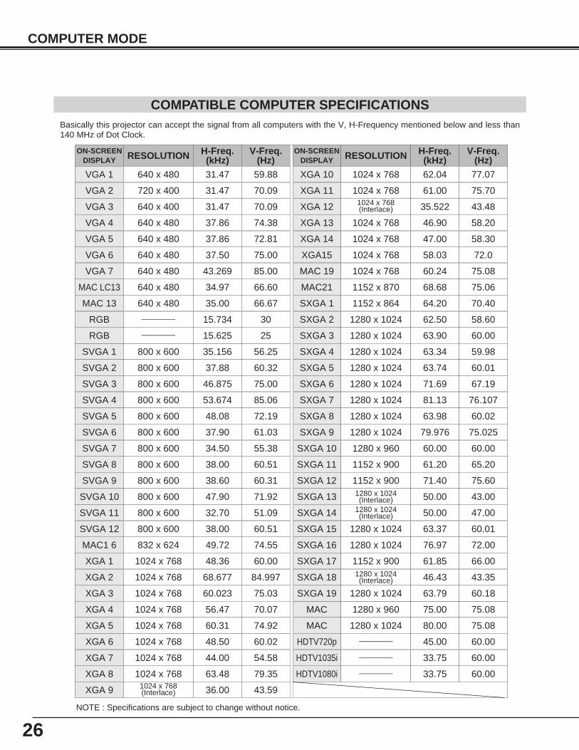
COMPATIBLE COMPUTER SPECIFICATIONSBasically this projector can accept the signal from all computers with the V, H-Frequency mentioned below and less than140 MHz of Dot Clock.
NOTE : Specifications are subject to change without notice.
ON-SCREENDISPLAY RESOLUTION H-Freq.
(kHz)V-Freq.
(Hz)VGA 1 640 x 480 31.47 59.88
VGA 2 720 x 400 31.47 70.09
VGA 3 640 x 400 31.47 70.09
VGA 4 640 x 480 37.86 74.38
VGA 5 640 x 480 37.86 72.81
VGA 6 640 x 480 37.50 75.00
MAC LC13 640 x 480 34.97 66.60
MAC 13 640 x 480 35.00 66.67
MAC1 6 832 x 624 49.72 74.55
MAC 19 1024 x 768 60.24 75.08
MAC21 1152 x 870 68.68 75.06
MAC 1280 x 960 75.00 75.08
MAC 1280 x 1024 80.00 75.08
SVGA 1 800 x 600 35.156 56.25
SVGA 2 800 x 600 37.88 60.32
SVGA 3 800 x 600 46.875 75.00
SVGA 4 800 x 600 53.674 85.06
SVGA 5 800 x 600 48.08 72.19
SVGA 6 800 x 600 37.90 61.03
SVGA 7 800 x 600 34.50 55.38
SVGA 8 800 x 600 38.00 60.51
SVGA 9 800 x 600 38.60 60.31
SVGA 11 800 x 600 32.70 51.09
SVGA 12 800 x 600 38.00 60.51
ON-SCREENDISPLAY RESOLUTION H-Freq.
(kHz)V-Freq.
(Hz)XGA 10 1024 x 768
XGA 11 1024 x 768
XGA 12 1024 x 768(Interlace)
XGA 13 1024 x 768
62.04 77.07
XGA 14 1024 x 768
61.00 75.70
XGA15 1024 x 768
35.522 43.48
46.90 58.20
XGA 8 1024 x 768
47.00 58.30
XGA 9 1024 x 768(Interlace)
58.03 72.0
SXGA 1 1152 x 864
SXGA 2 1280 x 1024
63.48 79.35
SXGA 3 1280 x 1024
36.00 43.59
SXGA 4 1280 x 1024
64.20 70.40
SXGA 5 1280 x 1024
62.50 58.60
SXGA 6 1280 x 1024
63.90 60.00
SXGA 7 1280 x 1024
63.34 59.98
SXGA 8 1280 x 1024
63.74 60.01
SXGA 11 1152 x 900
71.69 67.19
SXGA 12 1152 x 900
81.13 76.107
SXGA 13 1280 x 1024(Interlace)
63.98 60.02
SXGA 14 1280 x 1024(Interlace)
61.20 65.20
71.40 75.60
50.00 43.00
HDTV720p ––––––––
50.00 47.00
45.00 60.00
XGA 1 1024 x 768
XGA 2 1024 x 768
XGA 3 1024 x 768
XGA 4 1024 x 768
48.36 60.00
68.677 84.997
XGA 6 1024 x 768
60.023 75.03
XGA 7 1024 x 768
56.47 70.07
48.50 60.02
44.00 54.58
SXGA 9 1280 x 1024
SXGA 10 1280 x 960
79.976 75.025
60.00 60.00
SXGA 15 1280 x 1024
SXGA 16 1280 x 1024
SXGA 17 1152 x 900
SXGA 18 1280 x 1024(Interlace)
63.37 60.01
76.97 72.00
61.85 66.00
46.43 43.35
SXGA 19 1280 x 1024 63.79 60.18
XGA 5 1024 x 768 60.31 74.92
VGA 7 640 x 480 43.269 85.00
RGB –––––––– 15.625 25
RGB –––––––– 15.734 30
HDTV1080i –––––––– 33.75 60.00
HDTV1035i –––––––– 33.75 60.00
SVGA 10 800 x 600 47.90 71.92
27
COMPUTER MODE
PICTURE IMAGE ADJUSTMENT
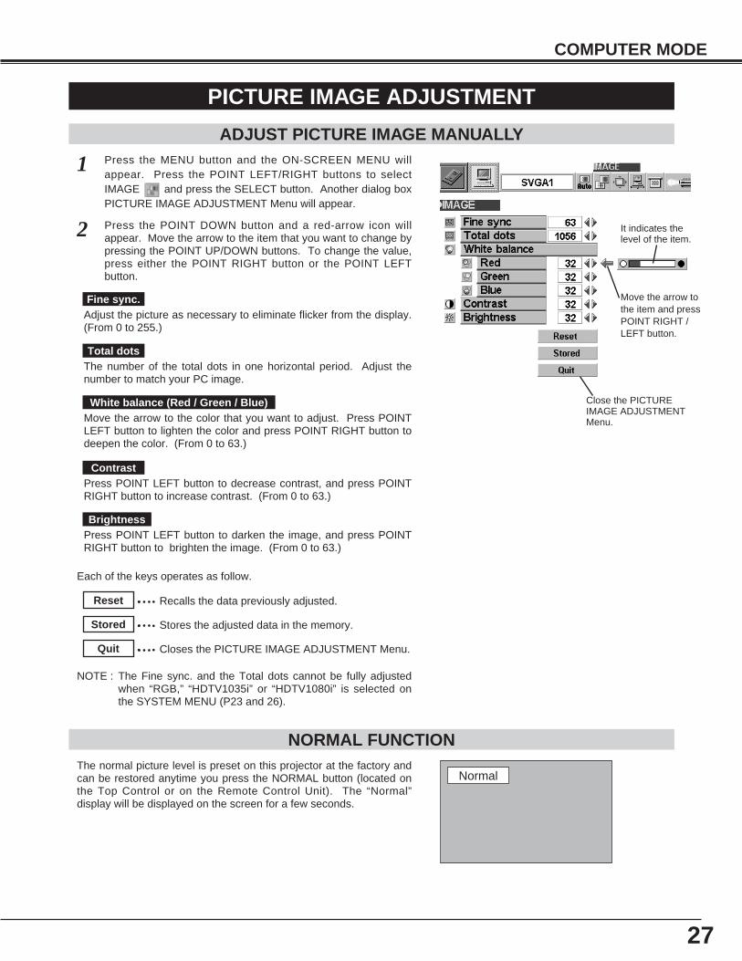
Press the MENU button and the ON-SCREEN MENU willappear. Press the POINT LEFT/RIGHT buttons to selectIMAGE and press the SELECT button. Another dialog boxPICTURE IMAGE ADJUSTMENT Menu will appear.
Press the POINT DOWN button and a red-arrow icon willappear. Move the arrow to the item that you want to change bypressing the POINT UP/DOWN buttons. To change the value,press either the POINT RIGHT button or the POINT LEFTbutton.
1
2
ADJUST PICTURE IMAGE MANUALLY
Adjust the picture as necessary to eliminate flicker from the display.(From 0 to 255.)
The number of the total dots in one horizontal period. Adjust thenumber to match your PC image.
Close the PICTUREIMAGE ADJUSTMENTMenu.
Move the arrow tothe item and pressPOINT RIGHT /LEFT button.
It indicates thelevel of the item.
Recalls the data previously adjusted.Reset
Stores the adjusted data in the memory.Stored
Closes the PICTURE IMAGE ADJUSTMENT Menu.Quit
Each of the keys operates as follow.
Fine sync.
Total dots
The normal picture level is preset on this projector at the factory andcan be restored anytime you press the NORMAL button (located onthe Top Control or on the Remote Control Unit). The “Normal”display will be displayed on the screen for a few seconds.
NORMAL FUNCTION
Normal
NOTE : The Fine sync. and the Total dots cannot be fully adjustedwhen “RGB,” “HDTV1035i” or “HDTV1080i” is selected onthe SYSTEM MENU (P23 and 26).
Press POINT LEFT button to decrease contrast, and press POINTRIGHT button to increase contrast. (From 0 to 63.)
Press POINT LEFT button to darken the image, and press POINTRIGHT button to brighten the image. (From 0 to 63.)
Move the arrow to the color that you want to adjust. Press POINTLEFT button to lighten the color and press POINT RIGHT button todeepen the color. (From 0 to 63.)
White balance (Red / Green / Blue)
Contrast
Brightness
28
COMPUTER MODE
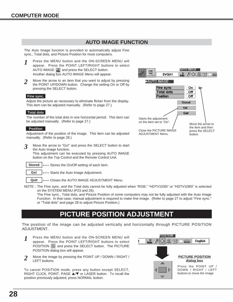
The Auto Image function is provided to automatically adjust Finesync., Total dots, and Picture Position for most computers.
Press the MENU button and the ON-SCREEN MENU willappear. Press the POINT LEFT/RIGHT buttons to selectAUTO IMAGE and press the SELECT button. Another dialog box AUTO IMAGE Menu will appear.
Move the arrow to an item that you want to adjust by pressingthe POINT UP/DOWN button. Change the setting On or Off bypressing the SELECT button.
1
2
AUTO IMAGE FUNCTION
Move the arrow to “Go!” and press the SELECT button to startthe Auto Image function. This adjustment can be executed by pressing AUTO IMAGEbutton on the Top Control and the Remote Control Unit.
3
Close the PICTURE IMAGEADJUSTMENT Menu.
Move the arrow tothe item and thenpress the SELECTbutton.
Starts the adjustmenton the item set to "On".
Adjust the picture as necessary to eliminate flicker from the display.This item can be adjusted manually. (Refer to page 27.)
The number of the total dots in one horizontal period. This item canbe adjusted manually. (Refer to page 27.)
Adjustment of the position of the image. This item can be adjustedmanually. (Refer to page 28.)
Fine sync.
Total dots
Position
Stores the On/Off setting of each item.Stored
Starts the Auto Image Adjustment.Go!
Closes the AUTO IMAGE ADJUSTMENT Menu.Quit
PICTURE POSITION ADJUSTMENTThe position of the image can be adjusted vertically and horizontally through PICTURE POSITIONADJUSTMENT.
Press the MENU button and the ON-SCREEN MENU willappear. Press the POINT LEFT/RIGHT buttons to selectPOSITION and press the SELECT button. The PICTUREPOSITION dialog box will appear.
Move the image by pressing the POINT UP / DOWN / RIGHT /LEFT buttons.
1
2 PICTURE POSITIONdialog box
Press the POINT UP /DOWN / RIGHT / LEFTbuttons to move the image
To cancel POSITION mode, press any button except SELECT,RIGHT CLICK, POINT, PAGE ▲/▼ or LASER button. To recall theposition previously adjusted, press NORMAL button.
NOTE : The Fine sync. and the Total dots cannot be fully adjusted when “RGB,” “HDTV1035i” or “HDTV1080i” is selectedon the SYSTEM MENU (P23 and 26).The Fine sync., Total dots, and Picture Position of some computers may not be fully adjusted with the Auto ImageFunction. In that case, manual adjustment is required to make fine image. (Refer to page 27 to adjust "Fine sync."or "Total dots" and page 28 to adjust Picture Position.)
29
COMPUTER MODE
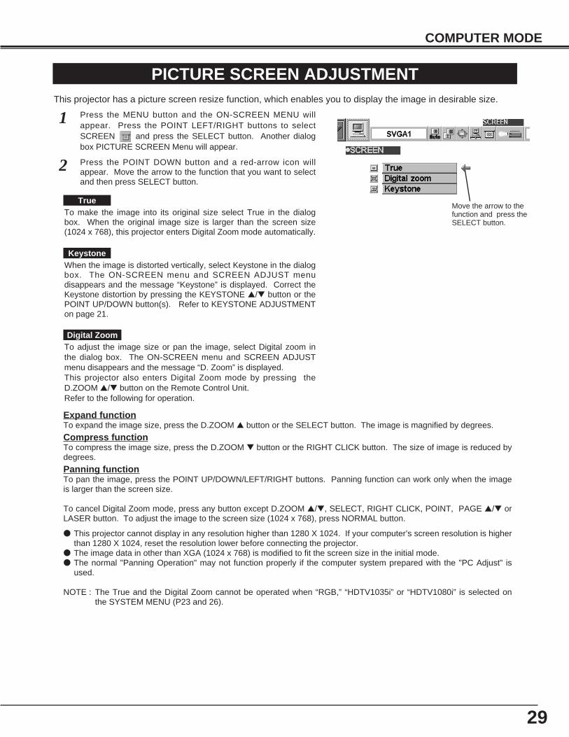
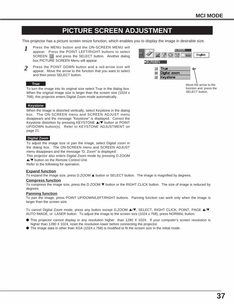
PICTURE SCREEN ADJUSTMENTThis projector has a picture screen resize function, which enables you to display the image in desirable size.
Press the MENU button and the ON-SCREEN MENU willappear. Press the POINT LEFT/RIGHT buttons to selectSCREEN and press the SELECT button. Another dialogbox PICTURE SCREEN Menu will appear.
1
Move the arrow to thefunction and press theSELECT button.
Press the POINT DOWN button and a red-arrow icon willappear. Move the arrow to the function that you want to selectand then press SELECT button.
2
To adjust the image size or pan the image, select Digital zoom inthe dialog box. The ON-SCREEN menu and SCREEN ADJUSTmenu disappears and the message “D. Zoom” is displayed. This projector also enters Digital Zoom mode by pressing theD.ZOOM ▲/▼ button on the Remote Control Unit. Refer to the following for operation.
● This projector cannot display in any resolution higher than 1280 X 1024. If your computer’s screen resolution is higherthan 1280 X 1024, reset the resolution lower before connecting the projector.
● The image data in other than XGA (1024 x 768) is modified to fit the screen size in the initial mode.● The normal "Panning Operation" may not function properly if the computer system prepared with the "PC Adjust" is
used.
NOTE : The True and the Digital Zoom cannot be operated when “RGB,” “HDTV1035i” or “HDTV1080i” is selected onthe SYSTEM MENU (P23 and 26).
Expand functionTo expand the image size, press the D.ZOOM ▲ button or the SELECT button. The image is magnified by degrees.
Compress functionTo compress the image size, press the D.ZOOM ▼ button or the RIGHT CLICK button. The size of image is reduced bydegrees.
Panning functionTo pan the image, press the POINT UP/DOWN/LEFT/RIGHT buttons. Panning function can work only when the imageis larger than the screen size.
To cancel Digital Zoom mode, press any button except D.ZOOM ▲/▼, SELECT, RIGHT CLICK, POINT, PAGE ▲/▼ orLASER button. To adjust the image to the screen size (1024 x 768), press NORMAL button.
To make the image into its original size select True in the dialogbox. When the original image size is larger than the screen size(1024 x 768), this projector enters Digital Zoom mode automatically.
True
Digital Zoom
KeystoneWhen the image is distorted vertically, select Keystone in the dialogbox. The ON-SCREEN menu and SCREEN ADJUST menudisappears and the message “Keystone” is displayed. Correct theKeystone distortion by pressing the KEYSTONE ▲/▼ button or thePOINT UP/DOWN button(s). Refer to KEYSTONE ADJUSTMENTon page 21.
30
VIDEO MODE
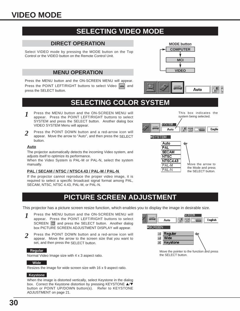
Press the MENU button and the ON-SCREEN MENU will appear.Press the POINT LEFT/RIGHT buttons to select Video andpress the SELECT button.
SELECTING VIDEO MODE
DIRECT OPERATIONSelect VIDEO mode by pressing the MODE button on the TopControl or the VIDEO button on the Remote Control Unit.
MENU OPERATION
SELECTING COLOR SYSTEMPress the MENU button and the ON-SCREEN MENU willappear. Press the POINT LEFT/RIGHT buttons to selectSYSTEM and press the SELECT button. Another dialog boxVIDEO SYSTEM Menu will appear.
Press the POINT DOWN button and a red-arrow icon willappear. Move the arrow to "Auto", and then press the SELECTbutton.
1
2
The projector automatically detects the incoming Video system, andadjusts itself to optimize its performance.When the Video System is PAL-M or PAL-N, select the systemmanually.
Auto
If the projector cannot reproduce the proper video image, it isrequired to select a specific broadcast signal format among PAL,SECAM, NTSC, NTSC 4.43, PAL-M, or PAL-N.
PAL / SECAM / NTSC / NTSC4.43 / PAL-M / PAL-N
Move the arrow tothe Mode and pressthe SELECT button.
PICTURE SCREEN ADJUSTMENTThis projector has a picture screen resize function, which enables you to display the image in desirable size.
Press the MENU button and the ON-SCREEN MENU willappear. Press the POINT LEFT/RIGHT buttons to selectSCREEN and press the SELECT button. Another dialogbox PICTURE SCREEN ADJUSTMENT DISPLAY will appear.
Press the POINT DOWN button and a red-arrow icon willappear. Move the arrow to the screen size that you want toset, and then press the SELECT button.
1
2
Normal Video Image size with 4 x 3 aspect ratio.
Resizes the image for wide screen size with 16 x 9 aspect ratio.
Move the pointer to the function and pressthe SELECT button.
Regular
Wide
KeystoneWhen the image is distorted vertically, select Keystone in the dialogbox. Correct the Keystone distortion by pressing KEYSTONE ▲/▼button or POINT UP/DOWN button(s). Refer to KEYSTONEADJUSTMENT on page 21.
This box indicates thesystem being selected.
COMPUTER
MCI
VIDEO
MODE button
31
Each of the keys operates as follow.
VIDEO MODE
PICTURE IMAGE ADJUSTMENT
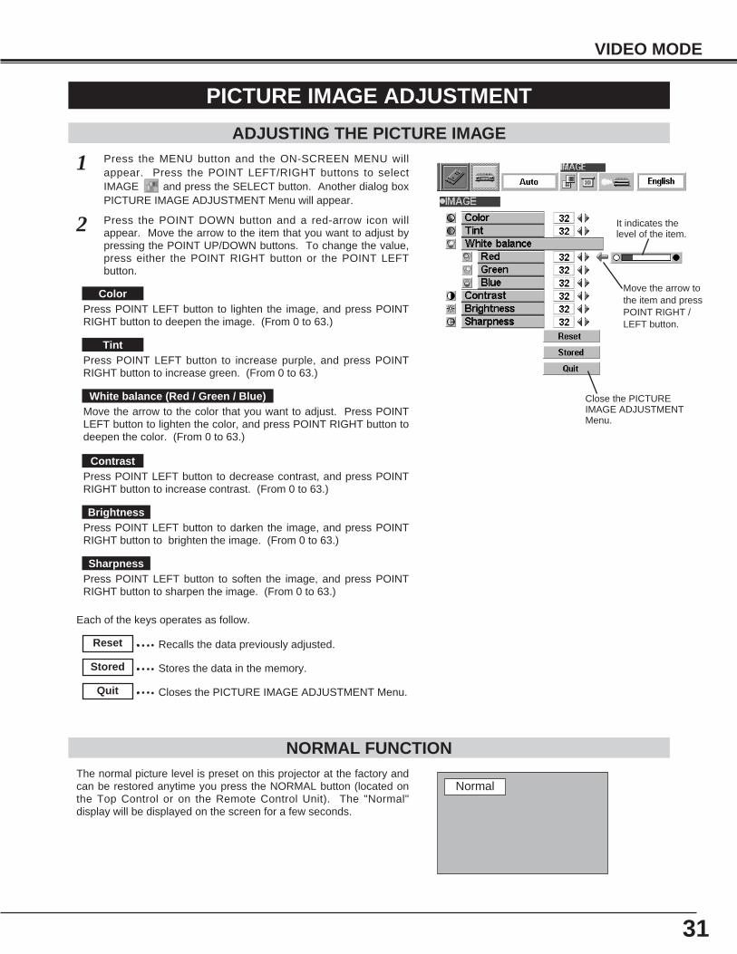
Press the MENU button and the ON-SCREEN MENU willappear. Press the POINT LEFT/RIGHT buttons to selectIMAGE and press the SELECT button. Another dialog boxPICTURE IMAGE ADJUSTMENT Menu will appear.
Press the POINT DOWN button and a red-arrow icon willappear. Move the arrow to the item that you want to adjust bypressing the POINT UP/DOWN buttons. To change the value,press either the POINT RIGHT button or the POINT LEFTbutton.
1
2
ADJUSTING THE PICTURE IMAGE
The normal picture level is preset on this projector at the factory andcan be restored anytime you press the NORMAL button (located onthe Top Control or on the Remote Control Unit). The "Normal"display will be displayed on the screen for a few seconds.
NORMAL FUNCTION
Recalls the data previously adjusted.Reset
Stores the data in the memory.Stored
Closes the PICTURE IMAGE ADJUSTMENT Menu.Quit
Normal
Press POINT LEFT button to lighten the image, and press POINTRIGHT button to deepen the image. (From 0 to 63.)
Press POINT LEFT button to increase purple, and press POINTRIGHT button to increase green. (From 0 to 63.)
Press POINT LEFT button to decrease contrast, and press POINTRIGHT button to increase contrast. (From 0 to 63.)
Press POINT LEFT button to darken the image, and press POINTRIGHT button to brighten the image. (From 0 to 63.)
Press POINT LEFT button to soften the image, and press POINTRIGHT button to sharpen the image. (From 0 to 63.)
Color
Tint
Contrast
Brightness
Sharpness
Move the arrow to the color that you want to adjust. Press POINTLEFT button to lighten the color, and press POINT RIGHT button todeepen the color. (From 0 to 63.)
White balance (Red / Green / Blue) Close the PICTUREIMAGE ADJUSTMENTMenu.
Move the arrow tothe item and pressPOINT RIGHT /LEFT button.
It indicates thelevel of the item.
32
MCI MODE
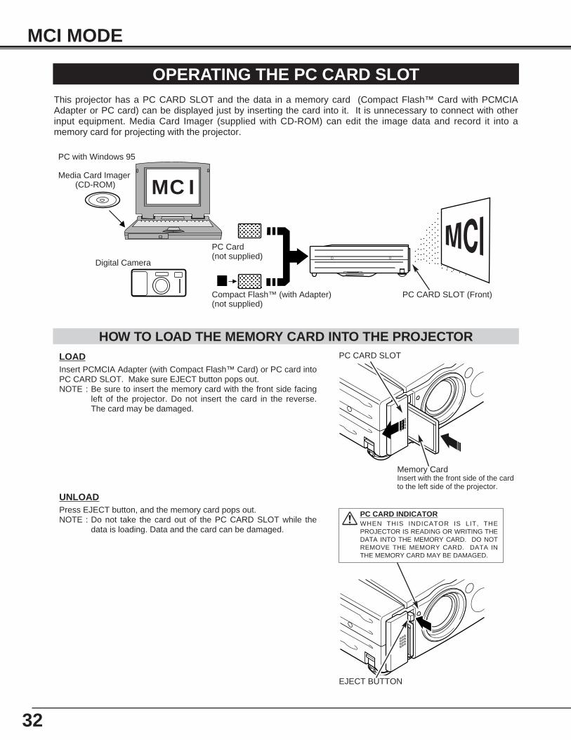
OPERATING THE PC CARD SLOTThis projector has a PC CARD SLOT and the data in a memory card (Compact Flash™ Card with PCMCIAAdapter or PC card) can be displayed just by inserting the card into it. It is unnecessary to connect with otherinput equipment. Media Card Imager (supplied with CD-ROM) can edit the image data and record it into amemory card for projecting with the projector.
MC I
HOW TO LOAD THE MEMORY CARD INTO THE PROJECTORLOADInsert PCMCIA Adapter (with Compact Flash™ Card) or PC card intoPC CARD SLOT. Make sure EJECT button pops out.NOTE : Be sure to insert the memory card with the front side facing
left of the projector. Do not insert the card in the reverse.The card may be damaged.
PC CARD SLOT
PC CARD SLOT (Front)
PC with Windows 95
Media Card Imager(CD-ROM)
Digital Camera
Compact Flash™ (with Adapter)(not supplied)
PC Card(not supplied)
UNLOADPress EJECT button, and the memory card pops out.NOTE : Do not take the card out of the PC CARD SLOT while the
data is loading. Data and the card can be damaged.
Memory Card Insert with the front side of the cardto the left side of the projector.
PC CARD INDICATORWHEN THIS INDICATOR IS LIT, THEPROJECTOR IS READING OR WRITING THEDATA INTO THE MEMORY CARD. DO NOTREMOVE THE MEMORY CARD. DATA INTHE MEMORY CARD MAY BE DAMAGED.
EJECT BUTTON
33
MCI MODE
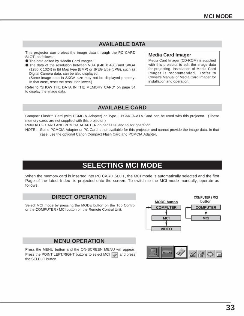
Press the MENU button and the ON-SCREEN MENU will appear.Press the POINT LEFT/RIGHT buttons to select MCI and pressthe SELECT button.
SELECTING MCI MODE
DIRECT OPERATIONSelect MCI mode by pressing the MODE button on the Top Controlor the COMPUTER / MCI button on the Remote Control Unit.
MENU OPERATION
COMPUTER / MCIbutton
COMPUTER
MCI
VIDEO
COMPUTER
MCI
MODE button
When the memory card is inserted into PC CARD SLOT, the MCI mode is automatically selected and the firstPage of the latest Index is projected onto the screen. To switch to the MCI mode manually, operate asfollows.
AVAILABLE DATA
AVAILABLE CARDCompact Flash™ Card (with PCMCIA Adapter) or Type || PCMCIA-ATA Card can be used with this projector. (Thosememory cards are not supplied with this projector.)Refer to CF CARD AND PCMCIA ADAPTER on pages 38 and 39 for operation.NOTE : Some PCMCIA Adapter or PC Card is not available for this projector and cannot provide the image data. In that
case, use the optional Canon Compact Flash Card and PCMCIA Adapter.
Media Card ImagerMedia Card Imager (CD-ROM) is suppliedwith this projector to edit the image datafor projecting. Installation of Media CardImager is recommended. Refer toOwner’s Manual of Media Card Imager forinstallation and operation.
This projector can project the image data through the PC CARDSLOT, as follows;● The data edited by “Media Card Imager.”● The data of the resolution between VGA (640 X 480) and SXGA
(1280 X 1024) in Bit Map type (BMP) or JPEG type (JPG), such asDigital Camera data, can be also displayed. (Some image data in SXGA size may not be displayed properly.In that case, reset the resolution lower.)
Refer to “SHOW THE DATA IN THE MEMORY CARD” on page 34to display the image data.
34
MCI MODE
Move the arrow toeach operation andpress the SELECTbutton.
SHOW THE DATA IN THE MEMORY CARD
BASIC OPERATION
Pages in the Index
Index
Select the Index
● This projector can project only image data in Bit Map or in JPEG format or the data edited by Media Card Imager(supplied) through the PC CARD SLOT. Other data is not compatible and should be edited and written to a memorycard with Media Card Imager before loading into PC CARD SLOT. (The data in Bit Map or in JPEG format, such as the data captured with a digital camera, can be projected directlythrough PC CARD SLOT.)
● If there is the data edited by Media Card Imager and other data (such as in Bit Map type or JPEG type) together in onememory card, the data edited by Media Card Imager has a priority to be projected with the LCD projector. The otherimage data in Bit Map type or JPEG type is not projected. In that case, edit that data and write it to the memory cardwith the Media Card Imager.
1
2
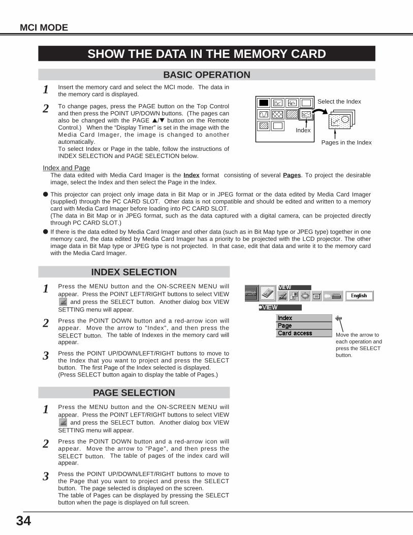
Insert the memory card and select the MCI mode. The data inthe memory card is displayed.
To change pages, press the PAGE button on the Top Controland then press the POINT UP/DOWN buttons. (The pages canalso be changed with the PAGE ▲/▼ button on the RemoteControl.) When the “Display Timer” is set in the image with theMedia Card Imager, the image is changed to anotherautomatically.To select Index or Page in the table, follow the instructions ofINDEX SELECTION and PAGE SELECTION below.
Index and PageThe data edited with Media Card Imager is the Index format consisting of several Pages. To project the desirableimage, select the Index and then select the Page in the Index.
INDEX SELECTION
PAGE SELECTION
1
2
Press the MENU button and the ON-SCREEN MENU willappear. Press the POINT LEFT/RIGHT buttons to select VIEW
and press the SELECT button. Another dialog box VIEWSETTING menu will appear.
Press the POINT DOWN button and a red-arrow icon willappear. Move the arrow to "Index", and then press theSELECT button. The table of Indexes in the memory card willappear.
3 Press the POINT UP/DOWN/LEFT/RIGHT buttons to move tothe Index that you want to project and press the SELECTbutton. The first Page of the Index selected is displayed. (Press SELECT button again to display the table of Pages.)
1
2
Press the MENU button and the ON-SCREEN MENU willappear. Press the POINT LEFT/RIGHT buttons to select VIEW
and press the SELECT button. Another dialog box VIEWSETTING menu will appear.
Press the POINT DOWN button and a red-arrow icon willappear. Move the arrow to "Page", and then press theSELECT button. The table of pages of the index card willappear.
3 Press the POINT UP/DOWN/LEFT/RIGHT buttons to move tothe Page that you want to project and press the SELECTbutton. The page selected is displayed on the screen.The table of Pages can be displayed by pressing the SELECTbutton when the page is displayed on full screen.
35
MCI MODE
WRITE DATA INTO THE MEMORY CARD
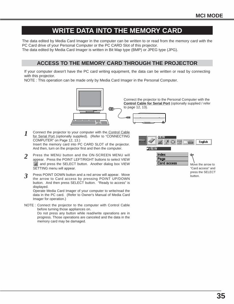
ACCESS TO THE MEMORY CARD THROUGH THE PROJECTORIf your computer doesn't have the PC card writing equipment, the data can be written or read by connectingwith this projector.NOTE : This operation can be made only by Media Card Imager in the Personal Computer.
The data edited by Media Card Imager in the computer can be written to or read from the memory card with thePC Card drive of your Personal Computer or the PC CARD Slot of this projector.The data edited by Media Card Imager is written in Bit Map type (BMP) or JPEG type (JPG).
NOTE : Connect the projector to the computer with Control Cablebefore turning those appliances on.Do not press any button while read/write operations are inprogress. Those operations are canceled and the data in thememory card may be damaged.
Connect the projector to the Personal Computer with theControl Cable for Serial Port (optionally supplied / referto page 12, 13).
Connect the projector to your computer with the Control Cablefor Serial Port (optionally supplied). (Refer to “CONNECTINGCOMPUTER” on Page 12, 13.)Insert the memory card into PC CARD SLOT of the projector.And then, turn on the projector first and then the computer.
1
2 Press the MENU button and the ON-SCREEN MENU willappear. Press the POINT LEFT/RIGHT buttons to select VIEW
and press the SELECT button. Another dialog box VIEWSETTING menu will appear.
3 Press POINT DOWN button and a red arrow will appear. Movethe arrow to Card access by pressing POINT UP/DOWNbutton. And then press SELECT button. “Ready to access” isdisplayed. Operate Media Card Imager of your computer to write/read thedata in the PC card. (Refer to Owner's Manual of Media CardImager for operation.)
Move the arrow to“Card access” andpress the SELECTbutton.
36
The position of the image can be adjusted vertically and horizontally through PICTURE POSITIONADJUSTMENT.
MCI MODE
PICTURE IMAGE ADJUSTMENT
ADJUST THE PICTURE IMAGE MANUALLY
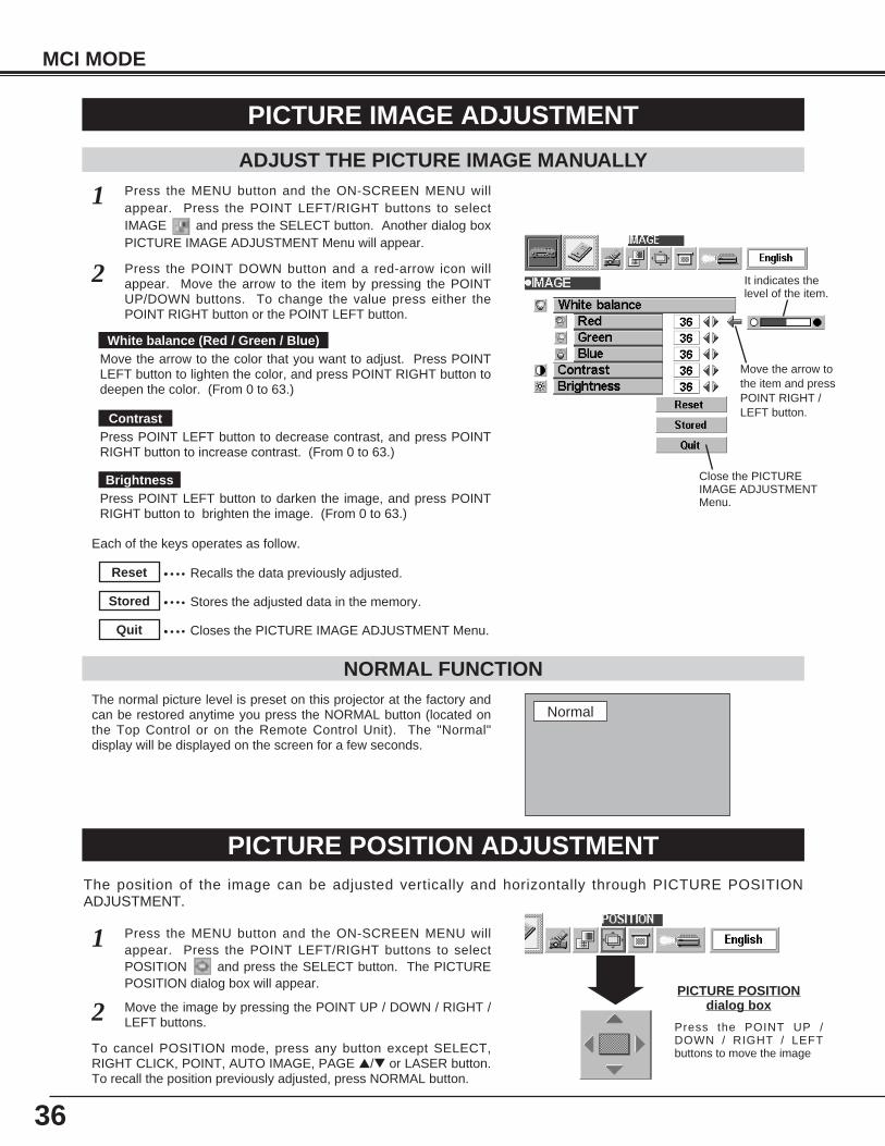
The normal picture level is preset on this projector at the factory andcan be restored anytime you press the NORMAL button (located onthe Top Control or on the Remote Control Unit). The "Normal"display will be displayed on the screen for a few seconds.
NORMAL FUNCTION
Press the MENU button and the ON-SCREEN MENU willappear. Press the POINT LEFT/RIGHT buttons to selectIMAGE and press the SELECT button. Another dialog boxPICTURE IMAGE ADJUSTMENT Menu will appear.
Press the POINT DOWN button and a red-arrow icon willappear. Move the arrow to the item by pressing the POINTUP/DOWN buttons. To change the value press either thePOINT RIGHT button or the POINT LEFT button.
1
2
Recalls the data previously adjusted.Reset
Stores the adjusted data in the memory.Stored
Closes the PICTURE IMAGE ADJUSTMENT Menu.Quit
Each of the keys operates as follow.
Close the PICTUREIMAGE ADJUSTMENTMenu.
Move the arrow tothe item and pressPOINT RIGHT /LEFT button.
It indicates thelevel of the item.
PICTURE POSITION ADJUSTMENT
Press the MENU button and the ON-SCREEN MENU willappear. Press the POINT LEFT/RIGHT buttons to selectPOSITION and press the SELECT button. The PICTUREPOSITION dialog box will appear.
Move the image by pressing the POINT UP / DOWN / RIGHT /LEFT buttons.
1
2PICTURE POSITION
dialog box
Press the POINT UP /DOWN / RIGHT / LEFTbuttons to move the image
Normal
To cancel POSITION mode, press any button except SELECT,RIGHT CLICK, POINT, AUTO IMAGE, PAGE ▲/▼ or LASER button.To recall the position previously adjusted, press NORMAL button.
Press POINT LEFT button to decrease contrast, and press POINTRIGHT button to increase contrast. (From 0 to 63.)
Press POINT LEFT button to darken the image, and press POINTRIGHT button to brighten the image. (From 0 to 63.)
Move the arrow to the color that you want to adjust. Press POINTLEFT button to lighten the color, and press POINT RIGHT button todeepen the color. (From 0 to 63.)
White balance (Red / Green / Blue)
Contrast
Brightness
37
MCI MODE
PICTURE SCREEN ADJUSTMENTThis projector has a picture screen resize function, which enables you to display the image in desirable size.
Press the MENU button and the ON-SCREEN MENU willappear. Press the POINT LEFT/RIGHT buttons to selectSCREEN and press the SELECT button. Another dialogbox PICTURE SCREEN Menu will appear.
To adjust the image size or pan the image, select Digital zoom inthe dialog box. The ON-SCREEN menu and SCREEN ADJUSTmenu disappears and the message “D. Zoom” is displayed. This projector also enters Digital Zoom mode by pressing D.ZOOM▲/▼ button on the Remote Control Unit. Refer to the following for operation.
1
● This projector cannot display in any resolution higher than 1280 X 1024. If your computer’s screen resolution ishigher than 1280 X 1024, reset the resolution lower before connecting the projector.
● The image data in other than XGA (1024 x 768) is modified to fit the screen size in the initial mode.
Expand functionTo expand the image size, press D.ZOOM ▲ button or SELECT button. The image is magnified by degrees.
Compress functionTo compress the image size, press the D.ZOOM ▼ button or the RIGHT CLICK button. The size of image is reduced bydegrees.
Panning functionTo pan the image, press POINT UP/DOWN/LEFT/RIGHT buttons. Panning function can work only when the image islarger than the screen size.
To cancel Digital Zoom mode, press any button except D.ZOOM ▲/▼, SELECT, RIGHT CLICK, POINT, PAGE ▲/▼,AUTO IMAGE, or LASER button. To adjust the image to the screen size (1024 x 768), press NORMAL button.
To turn the image into its original size select True in the dialog box.When the original image size is larger than the screen size (1024 x768), this projector enters Digital Zoom mode automatically.
Move the arrow to thefunction and press theSELECT button.
Press the POINT DOWN button and a red-arrow icon willappear. Move the arrow to the function that you want to selectand then press SELECT button.
2
True
Digital Zoom
KeystoneWhen the image is distorted vertically, select Keystone in the dialogbox. The ON-SCREEN menu and SCREEN ADJUST menudisappears and the message “Keystone” is displayed. Correct theKeystone distortion by pressing KEYSTONE ▲/▼ button or POINTUP/DOWN button(s). Refer to KEYSTONE ADJUSTMENT onpage 21.
38
MCI MODE
CF CARD AND PCMCIA ADAPTER
IMPORTANT NOTEData stored on a CF card may be damaged or lost due to physical damage to the CF card or accidentalerasure. It is recommended that any important data should be copied as a backup onto separate media,such as a floppy disk, a hard disk or a MO disk, etc. We shall not be liable for any damage or loss of profitsarising from the loss of data caused by the misoperation of or the damage to a CF card or its appliances.
The following may result in damaged or lost data:
• Misoperation of the CF card.
• Turning the LCD projector or the computer power off or removing the CF card / PCMCIA adapter while theCF card is in access operations (storing, reading or deleting the files).
• Exposure to a strong static electric charge.
• It has reached the end of its life.
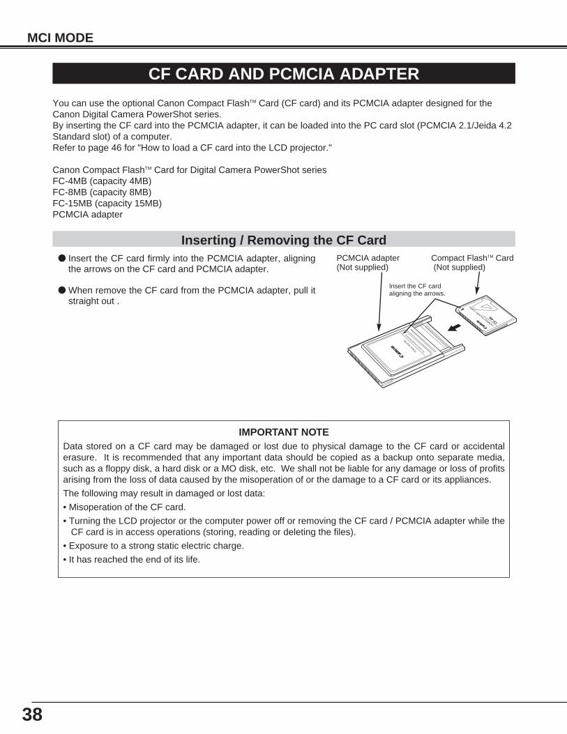
● Insert the CF card firmly into the PCMCIA adapter, aligningthe arrows on the CF card and PCMCIA adapter.
● When remove the CF card from the PCMCIA adapter, pull itstraight out .
You can use the optional Canon Compact FlashTM Card (CF card) and its PCMCIA adapter designed for theCanon Digital Camera PowerShot series.By inserting the CF card into the PCMCIA adapter, it can be loaded into the PC card slot (PCMCIA 2.1/Jeida 4.2Standard slot) of a computer.Refer to page 46 for "How to load a CF card into the LCD projector."
Canon Compact FlashTM Card for Digital Camera PowerShot seriesFC-4MB (capacity 4MB)FC-8MB (capacity 8MB)FC-15MB (capacity 15MB) PCMCIA adapter
For C
anon
Com
pactF
lash C
ard
PCMCIA ADAPTER
CF-4M
COMPACTFLASH CARD
PCMCIA adapter(Not supplied)
Compact FlashTM Card(Not supplied)
Insert the CF cardaligning the arrows.
Inserting / Removing the CF Card
39
MCI MODE
● Do not turn the LCD projector or the computer power off or remove the CF card / PCMCIA adapter whilethe CF card is in access operation (storing, reading or deleting files).
● CF cards / PCMCIA adapters are high-precision electronic devices. do not bend, drop, apply strong forcesor shock or place it where a strong static electrical charge may be generated.
● Do not touch the surface of the contact area with your fingers or allow it to be stained with foreign materials.
● Do not attempt to disassemble or alter CF cards.
● Moving CF card rapidly between hot and cold temperatures may cause condensation (water droplets) toform on it, leading to malfunctions. Avoid this problem by placing the CF card in a plastic bag and letting itslowly adjust to temperature changes before removing it from the bag. If condensation should occur, main-tain the CF card at a constant temperature and let the moisture evaporate naturally.
● Store CF cards / PCMCIA adapters in the protective case provided.
● Do not use or store CF cards / PCMCIA adapter in places subject to the following conditions:
strong magnetic fields
abundant dirt or dust
high temperatures, high humidity
SpecificationsInterface : PCMCIA / ATA PCMCIA 2.1/ JEIDA 4.2Card Slot Type : Type IIDimensions : 1.4 x 1.7 x 0.1 inches / 36.1 x 42.8 x 3.3 mm (CF card only)
3.4 x 2.1 x 0.2 inches / 86 x 54 x 5 mm (with PCMCIA Adapter)Weight : 0.4 oz / 10g (CF card only)
1.2 oz / 34g (with PCMCIA Adapter)
Subject to change without noticeWeight and dimensions are approximate.
Handling CF Card and PCMCIA Adapter
40
SETTING
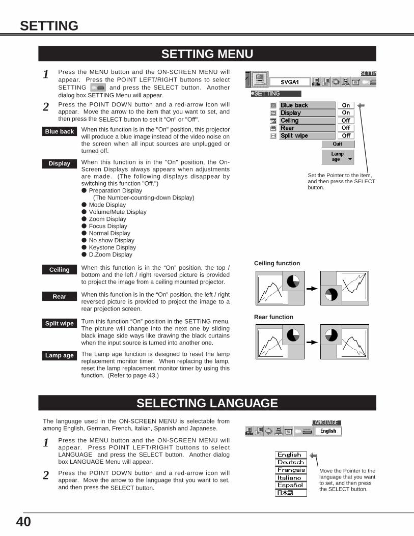
SETTING MENUPress the MENU button and the ON-SCREEN MENU willappear. Press the POINT LEFT/RIGHT buttons to selectSETTING and press the SELECT button. Anotherdialog box SETTING Menu will appear.
Press the POINT DOWN button and a red-arrow icon willappear. Move the arrow to the item that you want to set, andthen press the SELECT button to set it "On" or "Off".
1
2
Blue back When this function is in the "On" position, this projectorwill produce a blue image instead of the video noise onthe screen when all input sources are unplugged orturned off.
Display When this function is in the "On" position, the On-Screen Displays always appears when adjustmentsare made. (The following displays disappear byswitching this function "Off.")● Preparation Display
(The Number-counting-down Display)● Mode Display ● Volume/Mute Display● Zoom Display ● Focus Display ● Normal Display● No show Display ● Keystone Display ● D.Zoom Display
The Lamp age function is designed to reset the lampreplacement monitor timer. When replacing the lamp,reset the lamp replacement monitor timer by using thisfunction. (Refer to page 43.)
Lamp age
SELECTING LANGUAGE
Press the MENU button and the ON-SCREEN MENU willappear. Press POINT LEFT/RIGHT buttons to selectLANGUAGE and press the SELECT button. Another dialogbox LANGUAGE Menu will appear.
Press the POINT DOWN button and a red-arrow icon willappear. Move the arrow to the language that you want to set,and then press the SELECT button.
1
2
The language used in the ON-SCREEN MENU is selectable fromamong English, German, French, Italian, Spanish and Japanese.
Set the Pointer to the item,and then press the SELECTbutton.
Move the Pointer to thelanguage that you wantto set, and then pressthe SELECT button.
Ceiling When this function is in the “On” position, the top /bottom and the left / right reversed picture is providedto project the image from a ceiling mounted projector.
Rear When this function is in the “On” position, the left / rightreversed picture is provided to project the image to arear projection screen.
Split wipe Turn this function “On” position in the SETTING menu.The picture will change into the next one by slidingblack image side ways like drawing the black curtainswhen the input source is turned into another one.
Ceiling function
Rear function
41
APPENDIX
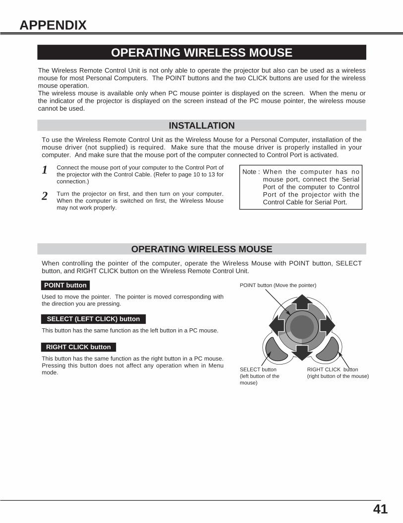
OPERATING WIRELESS MOUSE
INSTALLATION
The Wireless Remote Control Unit is not only able to operate the projector but also can be used as a wirelessmouse for most Personal Computers. The POINT buttons and the two CLICK buttons are used for the wirelessmouse operation.The wireless mouse is available only when PC mouse pointer is displayed on the screen. When the menu orthe indicator of the projector is displayed on the screen instead of the PC mouse pointer, the wireless mousecannot be used.
Connect the mouse port of your computer to the Control Port ofthe projector with the Control Cable. (Refer to page 10 to 13 forconnection.)
Turn the projector on first, and then turn on your computer.When the computer is switched on first, the Wireless Mousemay not work properly.
1
2
To use the Wireless Remote Control Unit as the Wireless Mouse for a Personal Computer, installation of themouse driver (not supplied) is required. Make sure that the mouse driver is properly installed in yourcomputer. And make sure that the mouse port of the computer connected to Control Port is activated.
OPERATING WIRELESS MOUSEWhen controlling the pointer of the computer, operate the Wireless Mouse with POINT button, SELECTbutton, and RIGHT CLICK button on the Wireless Remote Control Unit.
Used to move the pointer. The pointer is moved corresponding withthe direction you are pressing.
POINT button
This button has the same function as the left button in a PC mouse.
SELECT (LEFT CLICK) button
This button has the same function as the right button in a PC mouse.Pressing this button does not affect any operation when in Menumode.
RIGHT CLICK button
Note : When the computer has nomouse port, connect the SerialPort of the computer to ControlPort of the projector with theControl Cable for Serial Port.
POINT button (Move the pointer)
SELECT button(left button of themouse)
RIGHT CLICK button(right button of the mouse)
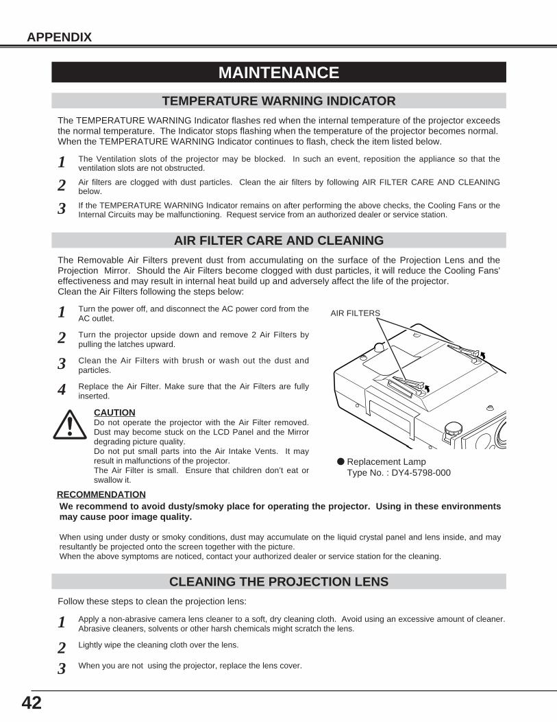
42
APPENDIX
CLEANING THE PROJECTION LENS
Apply a non-abrasive camera lens cleaner to a soft, dry cleaning cloth. Avoid using an excessive amount of cleaner.Abrasive cleaners, solvents or other harsh chemicals might scratch the lens.
When you are not using the projector, replace the lens cover.
1
3
Lightly wipe the cleaning cloth over the lens.2
Follow these steps to clean the projection lens:
MAINTENANCE
TEMPERATURE WARNING INDICATORThe TEMPERATURE WARNING Indicator flashes red when the internal temperature of the projector exceedsthe normal temperature. The Indicator stops flashing when the temperature of the projector becomes normal.When the TEMPERATURE WARNING Indicator continues to flash, check the item listed below.
The Ventilation slots of the projector may be blocked. In such an event, reposition the appliance so that theventilation slots are not obstructed.
Turn the power off, and disconnect the AC power cord from theAC outlet.
Turn the projector upside down and remove 2 Air Filters bypulling the latches upward.
1
2
The Removable Air Filters prevent dust from accumulating on the surface of the Projection Lens and theProjection Mirror. Should the Air Filters become clogged with dust particles, it will reduce the Cooling Fans'effectiveness and may result in internal heat build up and adversely affect the life of the projector.Clean the Air Filters following the steps below:
AIR FILTER CARE AND CLEANING
Clean the Air Filters with brush or wash out the dust andparticles.3
Air filters are clogged with dust particles. Clean the air filters by following AIR FILTER CARE AND CLEANINGbelow.
12
If the TEMPERATURE WARNING Indicator remains on after performing the above checks, the Cooling Fans or theInternal Circuits may be malfunctioning. Request service from an authorized dealer or service station.3
Replace the Air Filter. Make sure that the Air Filters are fullyinserted.4
AIR FILTERS
CAUTIONDo not operate the projector with the Air Filter removed.Dust may become stuck on the LCD Panel and the Mirrordegrading picture quality.Do not put small parts into the Air Intake Vents. It mayresult in malfunctions of the projector.The Air Filter is small. Ensure that children don’t eat orswallow it.
RECOMMENDATIONWe recommend to avoid dusty/smoky place for operating the projector. Using in these environmentsmay cause poor image quality.
When using under dusty or smoky conditions, dust may accumulate on the liquid crystal panel and lens inside, and mayresultantly be projected onto the screen together with the picture.When the above symptoms are noticed, contact your authorized dealer or service station for the cleaning.
● Replacement Lamp Type No. : DY4-5798-000
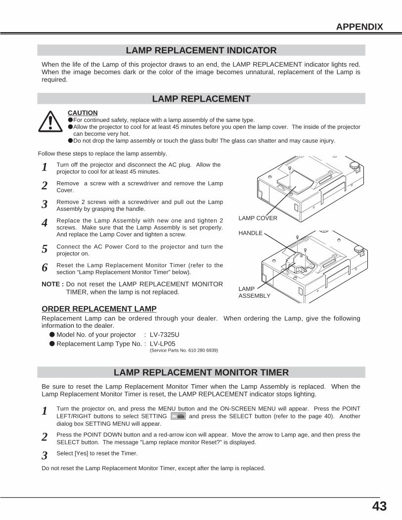
43
APPENDIX
LAMP REPLACEMENT INDICATORWhen the life of the Lamp of this projector draws to an end, the LAMP REPLACEMENT indicator lights red.When the image becomes dark or the color of the image becomes unnatural, replacement of the Lamp isrequired.
Turn off the projector and disconnect the AC plug. Allow theprojector to cool for at least 45 minutes.
Remove 2 screws with a screwdriver and pull out the LampAssembly by grasping the handle.
1
3
LAMP REPLACEMENT MONITOR TIMER
Replace the Lamp Assembly with new one and tighten 2screws. Make sure that the Lamp Assembly is set properly.And replace the Lamp Cover and tighten a screw.
4
LAMP REPLACEMENT
Remove a screw with a screwdriver and remove the LampCover.2
CAUTION● For continued safety, replace with a lamp assembly of the same type.● Allow the projector to cool for at least 45 minutes before you open the lamp cover. The inside of the projector
can become very hot.● Do not drop the lamp assembly or touch the glass bulb! The glass can shatter and may cause injury.
Be sure to reset the Lamp Replacement Monitor Timer when the Lamp Assembly is replaced. When theLamp Replacement Monitor Timer is reset, the LAMP REPLACEMENT indicator stops lighting.
Turn the projector on, and press the MENU button and the ON-SCREEN MENU will appear. Press the POINTLEFT/RIGHT buttons to select SETTING and press the SELECT button (refer to the page 40). Anotherdialog box SETTING MENU will appear.
1
Press the POINT DOWN button and a red-arrow icon will appear. Move the arrow to Lamp age, and then press theSELECT button. The message "Lamp replace monitor Reset?" is displayed.
2
Do not reset the Lamp Replacement Monitor Timer, except after the lamp is replaced.
Connect the AC Power Cord to the projector and turn theprojector on.
6
Follow these steps to replace the lamp assembly.
Reset the Lamp Replacement Monitor Timer (refer to thesection “Lamp Replacement Monitor Timer” below).
Select [Yes] to reset the Timer.3
5
LAMPASSEMBLY
HANDLE
LAMP COVER
NOTE : Do not reset the LAMP REPLACEMENT MONITORTIMER, when the lamp is not replaced.
ORDER REPLACEMENT LAMPReplacement Lamp can be ordered through your dealer. When ordering the Lamp, give the followinginformation to the dealer.
● Model No. of your projector : LV-7325U● Replacement Lamp Type No. : LV-LP05
(Service Parts No. 610 280 6939)
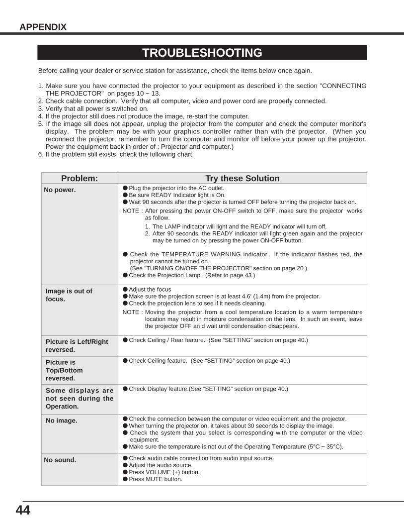
44
APPENDIX
TROUBLESHOOTINGBefore calling your dealer or service station for assistance, check the items below once again.
1. Make sure you have connected the projector to your equipment as described in the section "CONNECTINGTHE PROJECTOR" on pages 10 ~ 13.
2. Check cable connection. Verify that all computer, video and power cord are properly connected.3. Verify that all power is switched on.4. If the projector still does not produce the image, re-start the computer.5. If the image sill does not appear, unplug the projector from the computer and check the computer monitor's
display. The problem may be with your graphics controller rather than with the projector. (When youreconnect the projector, remember to turn the computer and monitor off before your power up the projector.Power the equipment back in order of : Projector and computer.)
6. If the problem still exists, check the following chart.
No power. ● Plug the projector into the AC outlet.● Be sure READY Indicator light is On.● Wait 90 seconds after the projector is turned OFF before turning the projector back on.
NOTE : After pressing the power ON-OFF switch to OFF, make sure the projector worksas follow.
1. The LAMP indicator will light and the READY indicator will turn off.2. After 90 seconds, the READY indicator will light green again and the projector
may be turned on by pressing the power ON-OFF button.
● Check the TEMPERATURE WARNING indicator. If the indicator flashes red, theprojector cannot be turned on.(See "TURNING ON/OFF THE PROJECTOR" section on page 20.)
● Check the Projection Lamp. (Refer to page 43.)
Image is out offocus.
● Adjust the focus● Make sure the projection screen is at least 4.6’ (1.4m) from the projector.● Check the projection lens to see if it needs cleaning.
NOTE : Moving the projector from a cool temperature location to a warm temperaturelocation may result in moisture condensation on the lens. In such an event, leavethe projector OFF an d wait until condensation disappears.
Picture is Left/Rightreversed.
● Check Ceiling / Rear feature. (See “SETTING” section on page 40.)
Problem: Try these Solution
Picture isTop/Bottomreversed.
● Check Ceiling feature. (See “SETTING” section on page 40.)
Some displays arenot seen during theOperation.
● Check Display feature.(See “SETTING” section on page 40.)
No image. ● Check the connection between the computer or video equipment and the projector.● When turning the projector on, it takes about 30 seconds to display the image.● Check the system that you select is corresponding with the computer or the video
equipment.● Make sure the temperature is not out of the Operating Temperature (5°C ~ 35°C).
No sound. ● Check audio cable connection from audio input source.● Adjust the audio source.● Press VOLUME (+) button.● Press MUTE button.
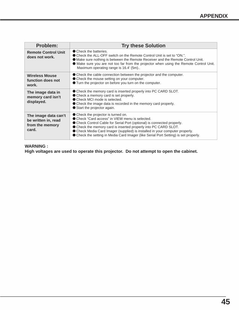
45
APPENDIX
WARNING :High voltages are used to operate this projector. Do not attempt to open the cabinet.
Remote Control Unitdoes not work.
● Check the batteries.● Check the ALL-OFF switch on the Remote Control Unit is set to “ON.”.● Make sure nothing is between the Remote Receiver and the Remote Control Unit.● Make sure you are not too far from the projector when using the Remote Control Unit.
Maximum operating range is 16.4’ (5m)..
Problem: Try these Solution
Wireless Mousefunction does notwork.
● Check the cable connection between the projector and the computer.● Check the mouse setting on your computer.● Turn the projector on before you turn on the computer.
The image data inmemory card isn’tdisplayed.
● Check the memory card is inserted properly into PC CARD SLOT.● Check a memory card is set properly.● Check MCI mode is selected.● Check the image data is recorded in the memory card properly.● Start the projector again.
The image data can’tbe written in, readfrom the memorycard.
● Check the projector is turned on.● Check “Card access” in VIEW menu is selected.● Check Control Cable for Serial Port (optional) is connected properly.● Check the memory card is inserted properly into PC CARD SLOT.● Check Media Card Imager (supplied) is installed in your computer properly.● Check the setting in Media Card Imager (like Serial Port Setting) is set properly.
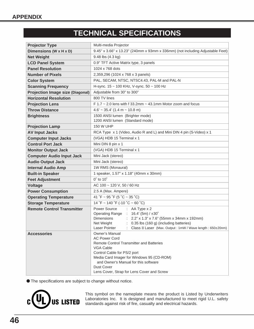
46
APPENDIX
0.9" TFT Active Matrix type, 3 panels
TECHNICAL SPECIFICATIONSMulti-media Projector
9.48 lbs (4.3 kg)
9.45" x 3.66" x 13.23" (240mm x 93mm x 336mm) (not including Adjustable Feet)
1024 x 768 dots
2,359,296 (1024 x 768 x 3 panels)
PAL, SECAM, NTSC, NTSC4.43, PAL-M and PAL-N
H-sync. 15 ~ 100 KHz, V-sync. 50 ~ 100 Hz
Adjustable from 30” to 300”
800 TV lines
1 speaker, 1.57" x 1.18" (40mm x 30mm)
AC 100 ~ 120 V, 50 / 60 Hz
2.5 A (Max. Ampere)
41 ˚F ~ 95 ˚F (5 ˚C ~ 35 ˚C)
14 ˚F ~ 140 ˚F (-10 ˚C ~ 60 ˚C)
Owner’s ManualAC Power CordRemote Control Transmitter and BatteriesVGA CableControl Cable for PS/2 port Media Card Imager for Windows 95 (CD-ROM)
and Owner's Manual for this softwareDust CoverLens Cover, Strap for Lens Cover and Screw
Projector Type
Net WeightDimensions (W x H x D)
Panel ResolutionNumber of PixelsColor SystemScanning FrequencyProjection Image size (Diagonal)
Horizontal Resolution
Built-in Speaker
VoltagePower ConsumptionOperating TemperatureStorage Temperature
Accessories
LCD Panel System
● The specifications are subject to change without notice.
F 1.7 ~ 2.0 lens with f 33.2mm ~ 43.1mm Motor zoom and focus
4.6’ ~ 35.4’ (1.4 m ~ 10.8 m)
150 W UHP
RCA Type x 1 (Video, Audio R and L) and Mini DIN 4 pin (S-Video) x 1
Projection LensThrow Distance
Projection LampAV Input Jacks
(VGA) HDB 15 Terminal x 1Computer Input JacksMini DIN 8 pin x 1
(VGA) HDB 15 Terminal x 1
Mini Jack (stereo)
Mini Jack (stereo)
1W RMS (Monaural)
Control Port JackMonitor Output JackComputer Audio Input JackAudio Output JackInternal Audio Amp
0˚ to 10˚Feet Adjustment
Power Source : AA Type x 2Operating Range : 16.4’ (5m) / ±30˚Dimensions : 2.2” x 1.3” x 7.6” (55mm x 34mm x 192mm)Net Weight : 0.35 lbs (160 g) (including batteries)Laser Pointer : Class II Laser (Max. Output : 1mW / Wave length : 650±20nm)
Remote Control Transmitter
This symbol on the nameplate means the product is Listed by UnderwritersLaboratories Inc. It is designed and manufactured to meet rigid U.L. safetystandards against risk of fire, casualty and electrical hazards.
1500 ANSI lumen (Brighter mode)1200 ANSI lumen (Standard mode)
Brightness
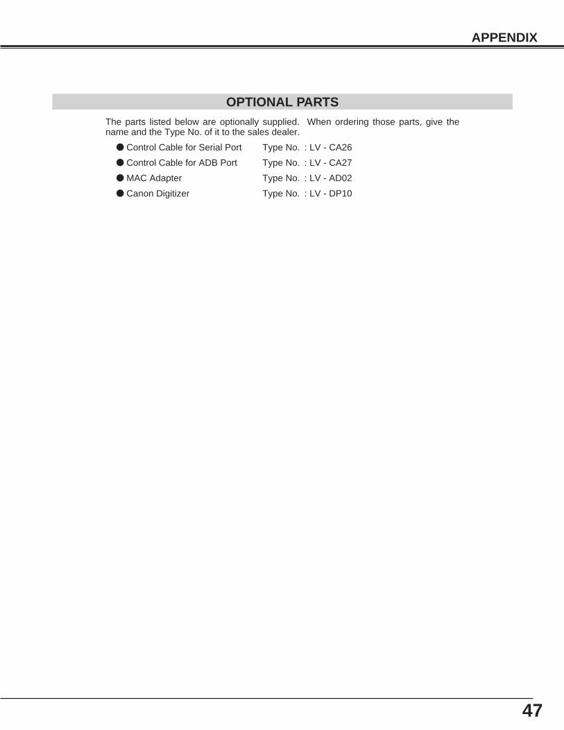
47
APPENDIX
OPTIONAL PARTSThe parts listed below are optionally supplied. When ordering those parts, give thename and the Type No. of it to the sales dealer.
● Control Cable for Serial Port Type No. : LV - CA26
● Control Cable for ADB Port Type No. : LV - CA27
● MAC Adapter Type No. : LV - AD02
● Canon Digitizer Type No. : LV - DP10
1AA6P1P2169-- (MB6S)
CANON INC. 30-2, Shimomaruko 3-chome, Ohta-ku, Tokyo 146-8501, Japan
CANON U.S.A., INC. NEW YORK OFFICEOne Canon Plaza, Lake Success, NY 11042-1198, U.S.A.phone : 516-328-5960
CANON U.S.A., INC. LOS ANGELES OFFICE15955 Alton Parkway, irvine, CA 92718-3616, U.S.A.phone : 949-753-4320
CANON CANADA, INC.6390 Dixie Road Mississauga, Ontario L5T 1P7 Canadaphone : 905-795-1111
©CANON INC. 2000YT1-1311-000 PRINTED IN JAPAN


