269
Multimedia Security: Steganography and Digital Watermarking Techniques for Protection of Intellectual Property Chun-Shien Lu IDEA GROUP PUBLISHING
| Date post: | 10-Dec-2016 |
| Category: |
Documents |
| Upload: | nguyentuyen |
| View: | 223 times |
| Download: | 4 times |

Multimedia Security:Steganography and Digital Watermarking Techniques
for Protection of Intellectual Property
Chun-Shien Lu
IDEA GROUP PUBLISHING

Hershey • London • Melbourne • Singapore��������� ��� ����
����������� ��������
��������� !�����
��������"�������#���
$��!��%��&�'��
�����������'
��������������� ����
Chun-Shien LuInstitute of Information Science
Academia Sinica, Taiwan, ROC

Acquisitions Editor: Mehdi Khosrow-PourSenior Managing Editor: Jan TraversManaging Editor: Amanda AppicelloDevelopment Editor: Michele RossiCopy Editor: Ingrid WiditzTypesetter: Jennifer WetzelCover Design: Lisa TosheffPrinted at: Yurchak Printing Inc.
Published in the United States of America byIdea Group Publishing (an imprint of Idea Group Inc.)701 E. Chocolate Avenue, Suite 200Hershey PA 17033Tel: 717-533-8845Fax: 717-533-8661E-mail: [email protected] site: http://www.idea-group.com
and in the United Kingdom byIdea Group Publishing (an imprint of Idea Group Inc.)3 Henrietta StreetCovent GardenLondon WC2E 8LUTel: 44 20 7240 0856Fax: 44 20 7379 3313Web site: http://www.eurospan.co.uk
Copyright © 2005 by Idea Group Inc. All rights reserved. No part of this book may be repro-duced in any form or by any means, electronic or mechanical, including photocopying, withoutwritten permission from the publisher.
Library of Congress Cataloging-in-Publication Data
Multimedia security : steganography and digital watermarking techniques forprotection of intellectual property / Chun-Shien Lu, Editor. p. cm. ISBN 1-59140-192-5 -- ISBN 1-59140-275-1 (ppb) -- ISBN 1-59140-193-3 (ebook) 1. Computer security. 2. Multimedia systems--Security measures. 3. Intellectual property. I. Lu,Chun-Shien. QA76.9.A25M86 2004 005.8--dc22 2004003775
British Cataloguing in Publication DataA Cataloguing in Publication record for this book is available from the British Library.
All work contributed to this book is new, previously-unpublished material. The views expressed inthis book are those of the authors, but not necessarily of the publisher.
����������� ��������
��������� !�������������
"�������#����$��!��%��&�'��
�����������'���������������� ����
$�(����'�)������&
Preface .............................................................................................................. v
Chapter IDigital Watermarking for Protection of Intellectual Property ................. 1
Mohamed Abdulla Suhail, University of Bradford, UK
Chapter IIPerceptual Data Hiding in Still Images .....................................................48
Mauro Barni, University of Siena, ItalyFranco Bartolini, University of Florence, ItalyAlessia De Rosa, University of Florence, Italy
Chapter IIIAudio Watermarking: Properties, Techniques and Evaluation ............75
Andrés Garay Acevedo, Georgetown University, USA
Chapter IVDigital Audio Watermarking .................................................................... 126
Changsheng Xu, Institute for Infocomm Research, SingaporeQi Tian, Institute for Infocomm Research, Singapore
Chapter VDesign Principles for Active Audio and Video Fingerprinting ........... 157
Martin Steinebach, Fraunhofer IPSI, GermanyJana Dittmann, Otto-von-Guericke-University Magdeburg, Germany
Chapter VIIssues on Image Authentication ............................................................. 173
Ching-Yung Lin, IBM T.J. Watson Research Center, USA
Chapter VIIDigital Signature-Based Image Authentication .................................... 207
Der-Chyuan Lou, National Defense University, TaiwanJiang-Lung Liu, National Defense University, TaiwanChang-Tsun Li, University of Warwick, UK
Chapter VIIIData Hiding in Document Images ........................................................... 231
Minya Chen, Polytechnic University, USANasir Memon, Polytechnic University, USAEdward K. Wong, Polytechnic University, USA
About the Authors ..................................................................................... 248
Index ............................................................................................................ 253
v
��'���
In this digital era, the ubiquitous network environment has promoted therapid delivery of digital multimedia data. Users are eager to enjoy the conve-nience and advantages that networks have provided. Meanwhile, users are ea-ger to share various media information in a rather cheap way without aware-ness of possibly violating copyrights. In view of these, digital watermarkingtechnologies have been recognized as a helpful way in dealing with the copy-right protection problem in the past decade. Although digital watermarking stillfaces some challenging difficulties for practical uses, there are no other tech-niques that are ready to substitute it. In order to push ahead with the develop-ment of digital watermarking technologies, the goal of this book is to collectboth comprehensive issues and survey papers in this field so that readers caneasily understand state of the art in multimedia security, and the challengingissues and possible solutions. In particular, the authors that contribute to thisbook have been well known in the related fields. In addition to the invited chap-ters, the other chapters are selected from a strict review process. In fact, theacceptance rate is lower than 50%.
There are eight chapters contained in this book. The first two chaptersprovide a general survey of digital watermarking technologies. In Chapter I, anextensive literature review of the multimedia copyright protection is thoroughlyprovided. It presents a universal review and background about the watermarkingdefinition, concept and the main contributions in this field. Chapter II focuseson the discussions of perceptual properties in image watermarking. In this chap-ter, a detailed description of the main phenomena regulating the HVS will begiven and the exploitation of these concepts in a data hiding system will beconsidered. Then, some limits of classical HVS models will be highlighted andsome possible solutions to get around these problems pointed out. Finally, acomplete mask building procedure, as a possible exploitation of HVS charac-teristics for perceptual data hiding in still images will be described.
From Chapter III through Chapter V, audio watermarking plays the mainrole. In Chapter III, the main theme is to propose a methodology, including

vi
performance metrics, for evaluating and comparing the performance of digitalaudio watermarking schemes. This is because the music industry is facing sev-eral challenges as well as opportunities as it tries to adapt its business to thenew medium. In fact, the topics discussed in this chapter come not only fromprinted sources but also from very productive discussions with some of theactive researchers in the field. These discussions have been conducted via e-mail, and constitute a rich complement to the still low number of printed sourcesabout this topic. Even though the annual number of papers published onwatermarking has been nearly doubling every year in the last years, it is stilllow. Thus it was necessary to augment the literature review with personal in-terviews. In Chapter IV, the aim is to provide a comprehensive survey andsummary of the technical achievements in the research area of digital audiowatermarking. In order to give a big picture of the current status of this area,this chapter covers the research aspects of performance evaluation for audiowatermarking, human auditory system, digital watermarking for PCM audio,digital watermarking for wav-table synthesis audio, and digital watermarkingfor compressed audio. Based on the current technology used in digital audiowatermarking and the demand from real-world applications, future promisingdirections are identified. In Chapter V, a method for embedding a customeridentification code into multimedia data is introduced. Specifically, the describedmethod, active digital fingerprinting, is a combination of robust digitalwatermarking and the creation of a collision-secure customer vector. There isalso another mechanism often called fingerprinting in multimedia security, whichis the identification of content with robust hash algorithms. To be able to distin-guish both methods, robust hashes are called passive fingerprinting and colli-sion-free customer identification watermarks are called active fingerprinting.Whenever we write fingerprinting in this chapter, we mean active fingerprint-ing.
In Chapters VI and VII, the media content authentication problem will bediscussed. It is well known that multimedia authentication distinguishes itselffrom other data integrity security issues because of its unique property of con-tent integrity in several different levels - from signal syntax levels to semanticlevels. In Chapter VI, several image authentication issues, including the math-ematical forms of optimal multimedia authentication systems, a description ofrobust digital signature, the theoretical bound of information hiding capacity ofimages, an introduction of the Self-Authentication-and-Recovery Image(SARI) system, and a novel technique for image/video authentication in thesemantic level will be thoroughly described. This chapter provides an overviewof these image authentication issues. On the other hand, in the light of thepossible disadvantages that watermarking-based authentication techniques mayresult in, Chapter VII has moved focus to labeling-based authentication tech-niques. In labeling-based techniques, the authentication information is conveyedin a separate file called label. A label is additional information associated with

vii
the image content and can be used to identify the image. In order to associatethe label content with the image content, two different ways can be employedand are stated as follows.
The last chapter describes watermarking methods applied to those mediadata that receives less attention. With the proliferation of digital media such asimages, audio, and video, robust digital watermarking and data hiding techniquesare needed for copyright protection, copy control, annotation, and authentica-tion of document images. While many techniques have been proposed for digi-tal color and grayscale images, not all of them can be directly applied to binaryimages in general and document images in particular. The difficulty lies in thefact that changing pixel values in a binary image could introduce irregularitiesthat are very visually noticeable. Over the last few years, we have seen agrowing but limited number of papers proposing new techniques and ideas forbinary image watermarking and data hiding. In Chapter VIII, an overview andsummary of recent developments on this important topic, and discussion ofimportant issues such as robustness and data hiding capacity of the differenttechniques is presented.

��#��*��������&
As the editor of this book, I would like to thank all the authors who havecontributed their chapters to this book during the lengthy process of compila-tion. In particular, I truly appreciate Idea Group Inc. for giving me the extensionof preparing the final book manuscript. Without your cooperation, this bookwould not be born.
Chun-Shien Lu, PhDAssistant Research FellowInstitute of Information Science, Academia SinicaTaipei City, Taiwan 115, Republic of China (ROC)[email protected]://www.iis.sinica.edu.tw/~lcs
viii

Digital Watermarking for Protection of Intellectual Property 1
Copyright © 2005, Idea Group Inc. Copying or distributing in print or electronic forms without writtenpermission of Idea Group Inc. is prohibited.
Chapter I
Digital Watermarkingfor Protection of
Intellectual PropertyMohamed Abdulla Suhail, University of Bradford, UK
ABSTRACTDigital watermarking techniques have been developed to protect thecopyright of media signals. This chapter aims to provide a universal reviewand background about the watermarking definition, concept and the maincontributions in this field. The chapter starts with a general view of digitaldata, the Internet and the products of these two, namely, the multimedia andthe e-commerce. Then, it provides the reader with some initial backgroundand history of digital watermarking. The chapter presents an extensive anddeep literature review of the field of digital watermarking and watermarkingalgorithms. It also highlights the future prospective of the digitalwatermarking.
INTRODUCTIONDigital watermarking techniques have been developed to protect the
copyright of media signals. Different watermarking schemes have been sug-gested for multimedia content (images, video and audio signal). This chapteraims to provide an extensive literature review of the multimedia copyrightprotection. It presents a universal review and background about the watermarkingdefinition, concept and the main contributions in this field. The chapter consistsof four main sections.
2 Suhail
Copyright © 2005, Idea Group Inc. Copying or distributing in print or electronic forms without writtenpermission of Idea Group Inc. is prohibited.
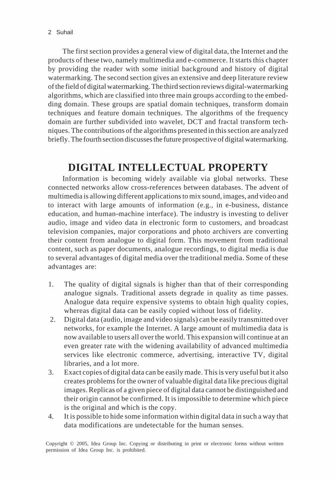
The first section provides a general view of digital data, the Internet and theproducts of these two, namely multimedia and e-commerce. It starts this chapterby providing the reader with some initial background and history of digitalwatermarking. The second section gives an extensive and deep literature reviewof the field of digital watermarking. The third section reviews digital-watermarkingalgorithms, which are classified into three main groups according to the embed-ding domain. These groups are spatial domain techniques, transform domaintechniques and feature domain techniques. The algorithms of the frequencydomain are further subdivided into wavelet, DCT and fractal transform tech-niques. The contributions of the algorithms presented in this section are analyzedbriefly. The fourth section discusses the future prospective of digital watermarking.
DIGITAL INTELLECTUAL PROPERTYInformation is becoming widely available via global networks. These
connected networks allow cross-references between databases. The advent ofmultimedia is allowing different applications to mix sound, images, and video andto interact with large amounts of information (e.g., in e-business, distanceeducation, and human-machine interface). The industry is investing to deliveraudio, image and video data in electronic form to customers, and broadcasttelevision companies, major corporations and photo archivers are convertingtheir content from analogue to digital form. This movement from traditionalcontent, such as paper documents, analogue recordings, to digital media is dueto several advantages of digital media over the traditional media. Some of theseadvantages are:
1. The quality of digital signals is higher than that of their correspondinganalogue signals. Traditional assets degrade in quality as time passes.Analogue data require expensive systems to obtain high quality copies,whereas digital data can be easily copied without loss of fidelity.
2. Digital data (audio, image and video signals) can be easily transmitted overnetworks, for example the Internet. A large amount of multimedia data isnow available to users all over the world. This expansion will continue at aneven greater rate with the widening availability of advanced multimediaservices like electronic commerce, advertising, interactive TV, digitallibraries, and a lot more.
3. Exact copies of digital data can be easily made. This is very useful but it alsocreates problems for the owner of valuable digital data like precious digitalimages. Replicas of a given piece of digital data cannot be distinguished andtheir origin cannot be confirmed. It is impossible to determine which pieceis the original and which is the copy.
4. It is possible to hide some information within digital data in such a way thatdata modifications are undetectable for the human senses.

Digital Watermarking for Protection of Intellectual Property 3
Copyright © 2005, Idea Group Inc. Copying or distributing in print or electronic forms without writtenpermission of Idea Group Inc. is prohibited.
E-CommerceModern electronic commerce (e-commerce) is a new activity that is the
direct result of a revolutionary information technology, digital data and theInternet. E-commerce is defined as the conduct of business transactions andtrading over a common information systems (IS) platform such as the Web orInternet. The amount of information being offered to public access grows at anamazing rate with current and new technologies. Technology used in e-commerce is allowing new, more efficient ways of carrying out existing businessand this has had an impact not only on commercial enterprises but also on sociallife. The e-commerce potential was developed through the World Wide Web(WWW) in the 1990s.
E-commerce can be divided into e-tailing, e-operations and e-fulfillment,all supported by an e-strategy. E-tailing involves the presentation of theorganization’s selling wares (goods/services) in the form of electronic cata-logues (e-catalogues). E-catalogues are an Internet version of the informationpresentation about the organization, its products, and so forth. E-operationscover the core transactional processes for production of goods and delivery ofservices. E-fulfillment is an area within e-commerce that still seems quiteblurred. It complements e-tailing and e-operations as it covers a range of post-retailing and operational issues. The core of e-fulfillment is payment systems,copyright protection of intellectual property, security (which includes privacy)and order management (i.e., supply chain, distribution, etc.). In essence, fulfill-ment is seen as the fuel to the growth and development of e-commerce.
The owners of copyright and related rights are granted a range of differentrights to control or be remunerated for various types of uses of their property(e.g., images, video, audio). One of these rights includes the right to excludeothers from reproducing the property without authorization. The development ofdigital technologies permitting transmission of digital data over the Internet hasraised questions about how these rights apply in the new environment. How candigital intellectual property be made publicly available while guaranteeingownership of the intellectual rights by the rights-holder and free access toinformation by the user?
Copyright Protection of Intellectual PropertyAn important factor that slows down the growth of multimedia networked
services is that authors, publishers and providers of multimedia data are reluctantto allow the distribution of their documents in a networked environment. This isbecause the ease of reproducing digital data in their exact original form is likelyto encourage copyright violation, data misappropriation and abuse. These are theproblems of theft and distribution of intellectual property. Therefore, creatorsand distributors of digital data are actively seeking reliable solutions to theproblems associated with copyright protection of multimedia data.

4 Suhail
Copyright © 2005, Idea Group Inc. Copying or distributing in print or electronic forms without writtenpermission of Idea Group Inc. is prohibited.
Moreover, the future development of networked multimedia systems, inparticular on open networks like the Internet, is conditioned by the developmentof efficient methods to protect data owners against unauthorized copying andredistribution of the material put on the network. This will guarantee that theirrights are protected and their assets properly managed. Copyright protection ofmultimedia data has been accomplished by means of cryptography algorithms toprovide control over data access and to make data unreadable to non-authorizedusers. However, encryption systems do not completely solve the problem,because once encryption is removed there is no more control on the dissemina-tion of data.
The concept of digital watermarking arose while trying to solve problemsrelated to the copyright of intellectual property in digital media. It is used as ameans to identify the owner or distributor of digital data. Watermarking is theprocess of encoding hidden copyright information since it is possible today to hideinformation messages within digital audio, video, images and texts, by taking intoaccount the limitations of the human audio and visual systems.
Digital Watermarking: What, Why, When and How?It seems that digital watermarking is a good way to protect intellectual
property from illegal copying. It provides a means of embedding a message in apiece of digital data without destroying its value. Digital watermarking embedsa known message in a piece of digital data as a means of identifying the rightfulowner of the data. These techniques can be used on many types of digital dataincluding still imagery, movies, and music. This chapter focuses on digitalwatermarking for images and in particular invisible watermarking.
What is Digital Watermarking?A digital watermark is a signal permanently embedded into digital data
(audio, images, video, and text) that can be detected or extracted later by meansof computing operations in order to make assertions about the data. Thewatermark is hidden in the host data in such a way that it is inseparable from thedata and so that it is resistant to many operations not degrading the hostdocument. Thus by means of watermarking, the work is still accessible butpermanently marked.
Digital watermarking techniques derive from steganography, which meanscovered writing (from the Greek words stegano or “covered” and graphos or“to write”). Steganography is the science of communicating information whilehiding the existence of the communication. The goal of steganography is to hidean information message inside harmless messages in such a way that it is notpossible even to detect that there is a secret message present. Both steganographyand watermarking belong to a category of information hiding, but the objectivesand conditions for the two techniques are just the opposite. In watermarking, for
Digital Watermarking for Protection of Intellectual Property 5
Copyright © 2005, Idea Group Inc. Copying or distributing in print or electronic forms without writtenpermission of Idea Group Inc. is prohibited.
example, the important information is the “external” data (e.g., images, voices,etc.). The “internal” data (e.g., watermark) are additional data for protecting theexternal data and to prove ownership. In steganography, however, the externaldata (referred to as a vessel, container, or dummy data) are not very important.They are just a carrier of the important information. The internal data are themost important.
On the other hand, watermarking is not like encryption. Watermarking doesnot restrict access to the data while encryption has the aim of making messagesunintelligible to any unauthorized persons who might intercept them. Onceencrypted data is decrypted, the media is no longer protected. A watermark isdesigned to permanently reside in the host data. If the ownership of a digital workis in question, the information can be extracted to completely characterize theowner.
Why Digital Watermarking?Digital watermarking is an enabling technology for e-commerce strategies:
conditional and user-specific access to services and resources. Digitalwatermarking offers several advantages. The details of a good digitalwatermarking algorithm can be made public knowledge. Digital watermarkingprovides the owner of a piece of digital data the means to mark the data invisibly.The mark could be used to serialize a piece of data as it is sold or used as a methodto mark a valuable image. For example, this marking allows an owner to safelypost an image for viewing but legally provides an embedded copyright to prohibitothers from posting the same image. Watermarks and attacks on watermarks aretwo sides of the same coin. The goal of both is to preserve the value of the digitaldata. However, the goal of a watermark is to be robust enough to resist attackbut not at the expense of altering the value of the data being protected. On theother hand, the goal of the attack is to remove the watermark without destroyingthe value of the protected data. The contents of the image can be marked withoutvisible loss of value or dependence on specific formats. For example a bitmap(BMP) image can be compressed to a JPEG image. The result is an image thatrequires less storage space but cannot be distinguished from the original.Generally, a JPEG compression level of 70% can be applied without humanlyvisible degradation. This property of digital images allows insertion of additionaldata in the image without altering the value of the image. The message is hiddenin unused “visual space” in the image and stays below the human visible thresholdfor the image.
When Did the Technique Originate?The idea of hiding data in another media is very old, as described in the case
of steganography. Nevertheless, the term digital watermarking first appearedin 1993, when Tirkel et al. (1993) presented two techniques to hide data in
6 Suhail
Copyright © 2005, Idea Group Inc. Copying or distributing in print or electronic forms without writtenpermission of Idea Group Inc. is prohibited.
images. These methods were based on modifications to the least significant bit(LSB) of the pixel values.
How Can We Build an Effective Watermarking Algorithm?The following sections will discuss further answering this question. How-
ever, it is desired that watermarks survive image-processing manipulations suchas rotation, scaling, image compression and image enhancement, for example.Taking advantage of the discrete wavelet transform properties and robustfeatures extraction techniques are the new trends that are used in the recentdigital image watermarking methods. Robustness against geometrical transfor-mation is essential since image-publishing applications often apply some kind ofgeometrical transformations to the image, and thus, an intellectual propertyownership protection system should not be affected by these changes.
DIGITAL WATERMARKING CONCEPTThis section aims to provide the theoretical background about the
watermarking field but concentrating mainly on digital images and the principlesby which watermarks are implemented. It discusses the requirements that areneeded for an effective watermarking system. It shows that the requirementsare application-dependent, but some of them are common to most practicalapplications. It explains also the challenges facing the researchers in this fieldfrom the digital watermarking requirement viewpoint. Swanson, Kobayashi andTewfik (1998), Busch and Wolthusen (1999), Mintzer, Braudaway and Yeung(1997), Servetto, Podilchuk and Ramchandran (1998), Cox, Kilian, Leighton andShamoon (1997), Bender, Gruhl, Morimoto and Lu (1996), Zaho, and Silvestreand Dowling (1997) include discussions of watermarking concepts and principlesand review developments in transparent data embedding for audio, image, andvideo media.
Visible vs. Invisible WatermarksDigital watermarking is divided into two main categories: visible and
invisible. The idea behind the visible watermark is very simple. It is equivalentto stamping a watermark on paper, and for this reason is sometimes said to bedigitally stamped. An example of visible watermarking is provided by televisionchannels, like BBC, whose logo is visibly superimposed on the corner of the TVpicture. Invisible watermarking, on the other hand, is a far more complexconcept. It is most often used to identify copyright data, like author, distributor,and so forth.

Digital Watermarking for Protection of Intellectual Property 7
Copyright © 2005, Idea Group Inc. Copying or distributing in print or electronic forms without writtenpermission of Idea Group Inc. is prohibited.
Though a lot of research has been done in the area of invisible watermarks,much less has been done for visible watermarks. Visible and invisible water-marks both serve to deter theft but they do so in very different ways. Visiblewatermarks are especially useful for conveying an immediate claim of owner-ship (Mintzer, Braudaway & Yeung, 1997). Their main advantage, in principleat least, is the virtual elimination of the commercial value of a document to awould-be thief, without lessening the document’s utility for legitimate, authorizedpurposes. Invisible watermarks, on the other hand, are more of an aid in catchinga thief than for discouraging theft in the first place (Mintzer et al., 1997; Swansonet al., 1998). This chapter focuses on the latter category, and the phrase“watermark” is taken to mean the invisible watermark, unless otherwise stated.
Watermarking ClassificationThere are different classifications of invisible watermarking algorithms.
The reason behind this is the enormous diversity of watermarking schemes.Watermarking approaches can be distinguished in terms of watermarking hostsignal (still images, video signal, audio signal, integrated circuit design), and theavailability of original signal during extraction (non-blind, semi-blind, blind). Also,they can be categorized based on the domain used for watermarking embeddingprocess, as shown in Figure 1. The watermarking application is considered oneof the criteria for watermarking classification. Figure 2 shows the subcategoriesbased on watermarking applications.
M o d ific a t io n L ea s tS ign if ic a n t B i t (L S B )
S p re ad S p e ct ru m
S p a tia l D o m a in
W a ve le t tran s fo rm (D W T )
C o s in e tra n s fo rm (D C T )
F rac ta l tran s fo rm a n d o th e rs
T ra n s fo rm D o m a in
S p a tia l d o m a in
T ran s fo rm d o m a in
F ea tu re D o m ain
W a te rm ark in g E m b ed d in g D o m a in
Figure 1. Classification of watermarking algorithms based on domain usedfor the watermarking embedding process

8 Suhail
Copyright © 2005, Idea Group Inc. Copying or distributing in print or electronic forms without writtenpermission of Idea Group Inc. is prohibited.
Digital Watermarking ApplicationWatermarking has been proposed in the literature as a means for different
applications. The four main digital watermarking applications are:
1. Copyright protection2. Image authentication3. Data hiding4. Covert communication
Figure 2 shows the different applications of watermarking with someexamples for each of these applications. Also, digital watermarking is proposedfor tracing images in the event of their illicit redistribution. The need for this hasarisen because modern digital networks make large-scale dissemination simpleand inexpensive. In the past, infringement of copyrighted documents was oftenlimited by the unfeasibility of large-scale photocopying and distribution. Inprinciple, digital watermarking makes it possible to uniquely mark each imagesold. If a purchaser then makes an illicit copy, the illicit duplication may beconvincingly demonstrated (Busch & Wolthusen, 1999; Swanson et al., 1998).
Watermark EmbeddingGenerally, watermarking systems for digital media involve two distinct
stages: (1) watermark embedding to indicate copyright and (2) watermarkdetection to identify the owner (Swanson et al., 1998). Embedding a watermarkrequires three functional components: a watermark carrier, a watermark gen-erator, and a carrier modifier. A watermark carrier is a list of data elements,selected from the un-watermarked signal, which are modified during theencoding of a sequence of noise-like signals that form the watermark. The noisesignals are generated pseudo-randomly, based on secret keys, independently ofthe carrier. Ideally, the signal should have the maximum amplitude, which is stillbelow the level of perceptibility (Cox et al., 1997; Silvestre & Dowling, 1997;
E lec tro n ic co m m e rceC opy C on tro l (e .g D VD )D istribu tio n o f m u lt im e d ia c on te n t
C opyrigh t P ro te c t ion
Fore nsic im a ge sA TM ca rds
Im a ge A u the n t ic a t ion
M e d ic a l im a gesC a rtogra phyB roa dc a st m o n ito ring
D a ta h id ing
D efe nse a pp lic a tio nsIn te llige nc e app lic a t ions
C ove rt C om m u nic a t ion
W a te rm a rk ing A pp lic a tions
Figure 2. Classification of watermarking technology based on applications
Digital Watermarking for Protection of Intellectual Property 9
Copyright © 2005, Idea Group Inc. Copying or distributing in print or electronic forms without writtenpermission of Idea Group Inc. is prohibited.
Swanson et al., 1998). The carrier modifier adds the generated noise signals tothe selected carrier. To balance the competing requirements for low perceptibil-ity and robustness of the added watermark, the noise must be scaled andmodulated according to the strength of the carrier.
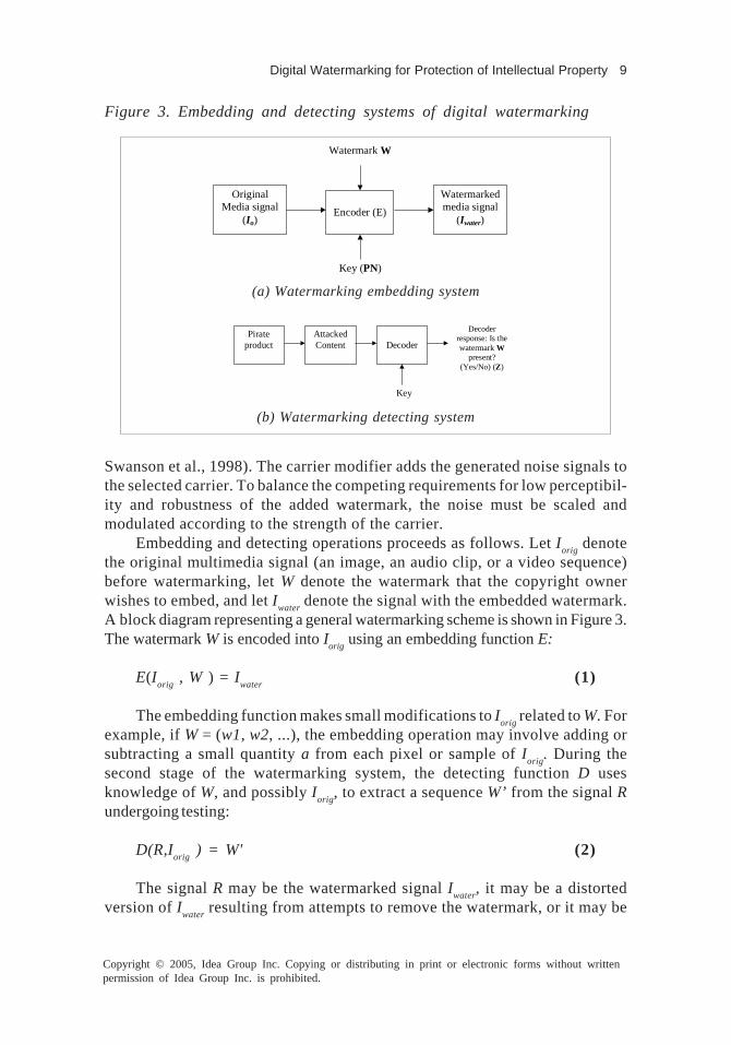
Embedding and detecting operations proceeds as follows. Let Iorig
denotethe original multimedia signal (an image, an audio clip, or a video sequence)before watermarking, let W denote the watermark that the copyright ownerwishes to embed, and let I
water denote the signal with the embedded watermark.
A block diagram representing a general watermarking scheme is shown in Figure 3.The watermark W is encoded into I
orig using an embedding function E:
E(Iorig
, W ) = Iwater
(1)
The embedding function makes small modifications to Iorig
related to W. Forexample, if W = (w1, w2, ...), the embedding operation may involve adding orsubtracting a small quantity a from each pixel or sample of I
orig. During the
second stage of the watermarking system, the detecting function D usesknowledge of W, and possibly I
orig, to extract a sequence W’ from the signal R
undergoing testing:
D(R,Iorig
) = W' (2)
The signal R may be the watermarked signal Iwater
, it may be a distortedversion of I
water resulting from attempts to remove the watermark, or it may be
OriginalMedia signal
(Io)Encoder (E)
Watermark W
Watermarkedmedia signal
(Iwater)
Key (PN)
Pirateproduct
AttackedContent Decoder
Decoderresponse: Is thewatermark W
present?(Yes/No) (Z)
Key
Figure 3. Embedding and detecting systems of digital watermarking
(a) Watermarking embedding system
(b) Watermarking detecting system

10 Suhail
Copyright © 2005, Idea Group Inc. Copying or distributing in print or electronic forms without writtenpermission of Idea Group Inc. is prohibited.
an unrelated signal. The extracted sequence W' is compared with the watermarkW to determine whether R is watermarked. The comparison is usually based ona correlation measure ρ, and a threshold λ
o used to make the binary decision (Z)
on whether the signal is watermarked or not. To check the similarity between W,the embedded watermark and W', the extracted one, the correlation measurebetween them can be found using:
''
')',(
WW
WWWW
⋅⋅=ρ (3)
where W, W' is the scalar product between these two vectors. However, thedecision function is:
Z(W’,W ) = λ≥ρ
otherwise0
,1 0(4)
where ρ is the value of the correlation and λ0 is a threshold. A 1 indicates a
watermark was detected, while a 0 indicates that a watermark was not detected.In other words, if W and W' are sufficiently correlated (greater than somethreshold λ
0), the signal R has been verified to contain the watermark that
confirms the author’s ownership rights to the signal. Otherwise, the owner of the
0 100 200 300 400 500 6000
0.1
0.2
0.3
0.4
0.5
0.6
0.7
0.8
0.9
1
Watermarks
Det
ecto
r R
espo
se
Magnitude of the detector response
OutputThreshold
Figure 4. Detection threshold experimentally (of 600 random watermarksequences studied, only one watermark — which was origanally inserted —has a higher correlation output above others) (Threshold is set to be 0.1 inthis graph.)

Digital Watermarking for Protection of Intellectual Property 11
Copyright © 2005, Idea Group Inc. Copying or distributing in print or electronic forms without writtenpermission of Idea Group Inc. is prohibited.
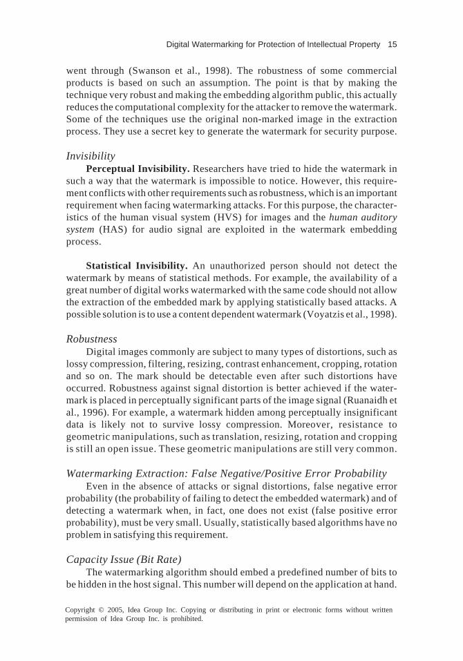
watermark W has no rights over the signal R. It is possible to derive the detectionthreshold λ
0 analytically or empirically by examining the correlation of random
sequences. Figure 4 shows the detection threshold of 600 random watermarksequences studied, and only one watermark, which was originally inserted, hasa significantly higher correlation output than the others. As an example of ananalytically defined threshold, τ can be defined as:
∑=cN
nmwaterIcN
|),(|3
ατ (5)
where α is a weighting factor and Nc is the number of coefficients that have been
marked. The formula is applicable to square and non-square images (Hernadez& Gonzalez, 1999). One can even just select certain coefficients (based on apseudo-random sequence or a human visual system (HVS) model). The choiceof the threshold influences the false-positive and false- negative probability.Hernandez and Gonzalez (1999) propose some methods to compute predictablecorrelation thresholds and efficient watermark detection systems.
A Watermarking ExampleA simple example of the basic watermarking process is described here. The
example is very basic just to illustrate how the watermarking process works. Thediscrete cosine transform (DCT) is applied on the host image, which isrepresented by the first block (8x8 pixel) of the “trees” image shown in Figure5. The block is given by:
0.7025
0.7025
0.7025
0.7025
0.7025
0.7025
0.7025
0.5880
0.7025 0.7025 0.7745 0.7745 0.7745 0.7025 0.7025
0.7745 0.7025 0.7745 0.7025 0.7025 0.7745 0.7025
0.7025 0.7745 0.7025 0.7745 0.7025 0.7025 0.7025
0.7025 0.7025 0.7025 0.7025 0.7745 0.7025 0.7745
0.7025 0.7745 0.7025 0.7025 0.7025 0.7025 0.7025
0.7025 0.7025 0.7745 0.7745 0.7025 0.7745 0.7745
0.7745 0.7025 0.7745 0.7025 0.7745 0.7745 0.7745
0.6122 0.6122 0.6003 0.7232 0.6599 0.8245 0.7232
1B
Block B1 of ‘trees’ image
Figure 5. ‘Trees’ image with its first 8x8 block

12 Suhail
Copyright © 2005, Idea Group Inc. Copying or distributing in print or electronic forms without writtenpermission of Idea Group Inc. is prohibited.
=
0.7025
0.7025
0.7025
0.7025
0.7025
0.7025
0.7025
0.5880
0.7025 0.7025 0.7745 0.7745 0.7745 0.7025 0.7025
0.7745 0.7025 0.7745 0.7025 0.7025 0.7745 0.7025
0.7025 0.7745 0.7025 0.7745 0.7025 0.7025 0.7025
0.7025 0.7025 0.7025 0.7025 0.7745 0.7025 0.7745
0.7025 0.7745 0.7025 0.7025 0.7025 0.7025 0.7025
0.7025 0.7025 0.7745 0.7745 0.7025 0.7745 0.7745
0.7745 0.7025 0.7745 0.7025 0.7745 0.7745 0.7745
0.6122 0.6122 0.6003 0.7232 0.6599 0.8245 0.7232
1B
Applying DCT on B1, the result is:
=
0.0329
0.0980-
0.0731-
0.0278-
0.0589-
0.0063
0.0336-
0.0070-
0.0422- 0.0084- 0.0286 0.0140- 0.0327 0.0697 0.0025
0.0105 0.0141 0.0518 0.0150- 0.0460- 0.0366 0.0422-
0.0586- 0.0361- 0.0200- 0.0240 0.0088 0.0064- 0.0790-
0.0526 0.0147 0.0093- 0.0355- 0.0034 0.0500 0.1066-
0.0031- 0.0182 0.0394- 0.0090- 0.0379 0.0436 0.0953-
0.0871- 0.0187- 0.0081- 0.0410- 0.0136- 0.0739 0.0354-
0.0415- 0.0114- 0.0137- 0.0104 0.0645 0.1157 0.0526-
0.0472- 0.0032- 0.0093- 0.0161 0.0379- 0.1162 5.7656
)( 1BDCT
Notice that most of the energy of the DCT of B1 is compact at the DC value
(DC coefficient =5.7656).The watermark, which is a pseudo-random real number generated using
random number generator and a seed value (key), is given by:
=
0.7771-
0.6312-
0.7952-
1.0894-
0.0374
2.5061
0.9269-
0.7167
0.6811- 1.7004 2.5359 0.2068 0.5532 1.7087- 0.1033-
0.1278 0.0855- 0.1994 0.3541 1.1233 1.7409- 0.0509
0.0007- 0.8294 0.3946- 1.1281- 1.6732 0.3008- 0.1303-
0.8054- 0.7764- 1.6061- 0.9099- 0.5224 1.8204 0.2059
1.1958- 0.1539 0.5422 1.4165- 0.0246- 0.8966 0.9424
0.3633- 0.1870 0.7859 0.0870- 1.6191 0.7000 0.7319
1.6095- 0.2174 0.4993 0.3888- 0.8350 0.6320- 0.7922
0.4570- 0.2259 1.0693- 1.6130- 0.8579- 0.2759 1.6505
W
Applying DCT on W, the result is:

Digital Watermarking for Protection of Intellectual Property 13
Copyright © 2005, Idea Group Inc. Copying or distributing in print or electronic forms without writtenpermission of Idea Group Inc. is prohibited.
=
0.5278-
0.0535
0.1452
0.8152-
0.5771-
0.3735
0.8266-
1.3164
0.7046- 0.4169 0.0656 1.5048- 0.9942 0.0380 0.4453
0.4119 0.7244- 0.3144- 0.2921- 0.7449 1.1217- 1.4724
0.1021- 0.1858 0.6200 0.0979- 1.2626 0.9041- 0.4222
0.9079- 0.9858- 0.0309- 1.2930 0.9799 0.5313 0.7653-
0.4434- 1.1027 1.7946- 0.0076- 1.5394 0.8337 1.7482-
0.8743 1.0022 1.3513 1.3837 1.3448- 1.4093- 0.0217
0.1335- 1.1665- 0.6162 0.2411- 2.8606 0.8694 0.1255
2.6675 1.0925- 0.3163- 0.7187 0.1714 1.5861 0.2390
)(WDCT
B1 is watermarked with W as shown in the block diagram in Figure 6
according to:
fw = f + α · w · f (6)
where f is a DCT coefficient of the host signal (B1), w is a DCT coefficient of
the watermark signal (W) and α is the watermarking energy, which is taken tobe 0.1 (α=0.1). The DC value of the host signal is not modified. This is tominimize the distortion of the watermarked image. Therefore, the DC value willbe kept un-watermarked.
The above equation can be rewritten in matrix format as follows:
⋅⋅+
=
valueDCforBDCT
valueDCexceptallforBDCTWDCTBDCTwBDCT
)1(
tcoefficien)1()()1()1(
α
(7)
where B1w
is the watermarked signal of B1. The result after applying the above
equation can be calculated as:
Frequency transform�
Frequency transform�
Encoder
= 0.1�
Watermark generator
�
Key�
Host signal�
+�
Watermarked image�
Inverse
Frequency transform
�
Figure 6. Basic block diagram of the watermarking process
α

14 Suhail
Copyright © 2005, Idea Group Inc. Copying or distributing in print or electronic forms without writtenpermission of Idea Group Inc. is prohibited.
=
0.0312
0.0985-
0.0742-
0.0255-
0.0555-
0.0066
0.0308-
0.0079-
0.0392- 0.0088- 0.0288 0.0119- 0.0360 0.0700 0.0026
0.0109 0.0131 0.0502 0.0146- 0.0494- 0.0325 0.0485-
0.0580- 0.0368- 0.0212- 0.0238 0.0099 0.0058- 0.0823-
0.0478 0.0132 0.0092- 0.0400- 0.0037 0.0527 0.0984-
0.0029- 0.0202 0.0323- 0.0090- 0.0438 0.0472 0.0786-
0.0947- 0.0206- 0.0092- 0.0467- 0.0117- 0.0635 0.0355-
0.0409- 0.0101- 0.0145- 0.0101 0.0830 0.1258 0.0532-
0.0598- 0.0028- 0.0090- 0.0172 0.0386- 0.1346 5.7656
BDCT w)( 1
Notice that the DC value of DCT(B1w
)is the same as the DC value ofDCT(B
1). To construct the watermarked image, the inverse DCT of the above
two-dimensional array is computed to give:
=
0.6974
0.6992
0.6978
0.6996
0.6933
0.6920
0.6998
0.5922
0.7044 0.7001 0.7793 0.7800 0.7712 0.7048 0.6877
0.7736 0.7026 0.7765 0.7067 0.7002 0.7765 0.7017
0.7015 0.7741 0.7078 0.7801 0.7026 0.7032 0.7051
0.7013 0.7012 0.7067 0.7081 0.7789 0.7100 0.7872
0.6986 0.7692 0.7013 0.7037 0.7045 0.7093 0.7064
0.6956 0.7002 0.7663 0.7682 0.6973 0.7746 0.7734
0.7755 0.6955 0.7712 0.7011 0.7735 0.7809 0.7818
0.6175 0.6026 0.5991 0.7228 0.6609 0.8361 0.7331
1wB
It is easy to compare B1w
and B1 and see the very slight modification due to
the watermark.
Robust Watermarking Scheme RequirementsIn this section, the requirements needed for an effective watermarking
system are introduced. The requirements are application-dependent, but some ofthem are common to most practical applications. One of the challenges forresearchers in this field is that these requirements compete with each other. Suchgeneral requirements are listed below. Detailed discussions of them can be foundin Petitcolas (n.d.), Voyatzis, Nikolaidis and Pitas (1998), Ruanaidh, Dowling andBoland (1996), Ruanaidh and Pun (1997), Hsu and Wu (1996), Ruanaidh, Bolandand Dowling (1996), Hernandez, Amado and Perez-Gonzalez (2000), Swanson,Zhu and Tewfik (1996), Wolfgang and Delp (1996), Craver, Memon, Yeo andYeung (1997), Zeng and Liu (1997), and Cox and Miller (1997).
SecurityEffectiveness of a watermark algorithm cannot be based on the assumption
that possible attackers do not know the embedding process that the watermark
Digital Watermarking for Protection of Intellectual Property 15
Copyright © 2005, Idea Group Inc. Copying or distributing in print or electronic forms without writtenpermission of Idea Group Inc. is prohibited.
went through (Swanson et al., 1998). The robustness of some commercialproducts is based on such an assumption. The point is that by making thetechnique very robust and making the embedding algorithm public, this actuallyreduces the computational complexity for the attacker to remove the watermark.Some of the techniques use the original non-marked image in the extractionprocess. They use a secret key to generate the watermark for security purpose.
InvisibilityPerceptual Invisibility. Researchers have tried to hide the watermark in
such a way that the watermark is impossible to notice. However, this require-ment conflicts with other requirements such as robustness, which is an importantrequirement when facing watermarking attacks. For this purpose, the character-istics of the human visual system (HVS) for images and the human auditorysystem (HAS) for audio signal are exploited in the watermark embeddingprocess.
Statistical Invisibility. An unauthorized person should not detect thewatermark by means of statistical methods. For example, the availability of agreat number of digital works watermarked with the same code should not allowthe extraction of the embedded mark by applying statistically based attacks. Apossible solution is to use a content dependent watermark (Voyatzis et al., 1998).
RobustnessDigital images commonly are subject to many types of distortions, such as
lossy compression, filtering, resizing, contrast enhancement, cropping, rotationand so on. The mark should be detectable even after such distortions haveoccurred. Robustness against signal distortion is better achieved if the water-mark is placed in perceptually significant parts of the image signal (Ruanaidh etal., 1996). For example, a watermark hidden among perceptually insignificantdata is likely not to survive lossy compression. Moreover, resistance togeometric manipulations, such as translation, resizing, rotation and croppingis still an open issue. These geometric manipulations are still very common.
Watermarking Extraction: False Negative/Positive Error ProbabilityEven in the absence of attacks or signal distortions, false negative error
probability (the probability of failing to detect the embedded watermark) and ofdetecting a watermark when, in fact, one does not exist (false positive errorprobability), must be very small. Usually, statistically based algorithms have noproblem in satisfying this requirement.
Capacity Issue (Bit Rate)The watermarking algorithm should embed a predefined number of bits to
be hidden in the host signal. This number will depend on the application at hand.
16 Suhail
Copyright © 2005, Idea Group Inc. Copying or distributing in print or electronic forms without writtenpermission of Idea Group Inc. is prohibited.
There is no general rule for this. However, in the image case, the possibility ofembedding into the image at least 300-400 bits should be guaranteed. In general,the number of bits that can be hidden in data is limited. Capacity issues werediscussed by Servetto et al. (1998).
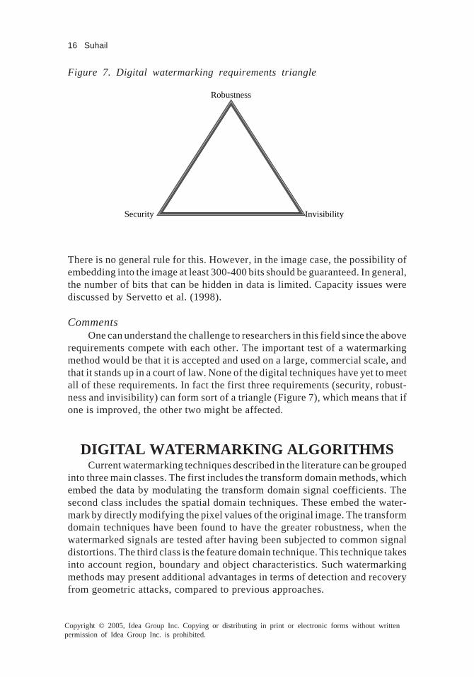
CommentsOne can understand the challenge to researchers in this field since the above
requirements compete with each other. The important test of a watermarkingmethod would be that it is accepted and used on a large, commercial scale, andthat it stands up in a court of law. None of the digital techniques have yet to meetall of these requirements. In fact the first three requirements (security, robust-ness and invisibility) can form sort of a triangle (Figure 7), which means that ifone is improved, the other two might be affected.
DIGITAL WATERMARKING ALGORITHMSCurrent watermarking techniques described in the literature can be grouped
into three main classes. The first includes the transform domain methods, whichembed the data by modulating the transform domain signal coefficients. Thesecond class includes the spatial domain techniques. These embed the water-mark by directly modifying the pixel values of the original image. The transformdomain techniques have been found to have the greater robustness, when thewatermarked signals are tested after having been subjected to common signaldistortions. The third class is the feature domain technique. This technique takesinto account region, boundary and object characteristics. Such watermarkingmethods may present additional advantages in terms of detection and recoveryfrom geometric attacks, compared to previous approaches.
Invisibility Security
Robustness
Figure 7. Digital watermarking requirements triangle

Digital Watermarking for Protection of Intellectual Property 17
Copyright © 2005, Idea Group Inc. Copying or distributing in print or electronic forms without writtenpermission of Idea Group Inc. is prohibited.
In this chapter, the algorithms in this survey are organized according to theirembedding domain, as indicated in Figure 1. These are grouped into:
1. spatial domain techniques2. transform domain techniques3. feature domain techniques
However, due to the amount of published work in the field of watermarkingtechnology, the main focus will be on wavelet-based watermarking techniquepapers. The wavelet domain is the most efficient domain for watermarkingembedding so far. However, the review considers some other techniques, whichserve the purpose of giving a broader picture of the existing watermarkingalgorithms. Some examples of spatial domain and fractal-based techniques willbe reviewed.
Spatial Domain TechniquesThis section gives a brief introduction to the spatial domain technique to give
the reader some background information about watermarking in this domain.Many spatial techniques are based on adding fixed amplitude pseudo noise (PN)sequences to an image. In this case, E and D (as introduced in previous section)are simply the addition and subtraction operators, respectively. PN sequencesare also used as the “spreading key” when considering the host media as thenoise in a spread spectrum system, where the watermark is the transmittedmessage. In this case, the PN sequence is used to spread the data bits over thespectrum to hide the data.
When applied in the spatial or temporal domains, these approaches modifythe least significant bits (LSB) of the host data. The invisibility of the watermarkis achieved on the assumption that the LSB data are visually insignificant. Thewatermark is generally recovered using knowledge of the PN sequence (andperhaps other secret keys, like watermark location) and the statistical propertiesof the embedding process. Two LSB techniques are described in Schyndel,Tirkel and Osborne (1994). The first replaces the LSB of the image with a PNsequence, while the second adds a PN sequence to the LSB of the data. InBender et al. (1996), a direct sequence spread spectrum technique is proposedto embed a watermark in host signals. One of these, LSB-based, is a statisticaltechnique that randomly chooses n pairs of points (a
i, b
i ) in an image and
increases the brightness of ai by one unit while simultaneously decreasing the
brightness of bi. Another PN sequence spread spectrum approach is proposed
in Wolfgang and Delp (1996), where the authors hide data by adding a fixedamplitude PN sequence to the image. Wolfgang and Delp add fixed amplitude 2DPN sequence obtained from a long 1D PN sequence to the image. In Schyndelet al. (1994) and Pitas and Kaskalis (1995), an image is randomly split into two
18 Suhail
Copyright © 2005, Idea Group Inc. Copying or distributing in print or electronic forms without writtenpermission of Idea Group Inc. is prohibited.
subsets of equal size. The mean value of one of the subsets is increased by aconstant factor k. In effect, the scheme adds high frequency noise to the image.
In Tanaka, Nakamura and Matsui (1990), the watermarking algorithms usea predictive coding scheme to embed the watermark into the image. Also, thewatermark is embedded into the image by dithering the image based on thestatistical properties of the image. In Bruyndonckx, Quisquater and Macq(1995), a watermark for an image is generated by modifying the luminancevalues inside 8x8 blocks of pixels, adding one extra bit of information to eachblock. The encoder secretly makes the choice of the modified block. The XeroxData Glyph technology (Swanson et al., 1998) adds a bar code to its imagesaccording to a predetermined set of geometric modifications. Hirotsugu (1996)constructs a watermark by concealing graph data in the LSBs of the image.
In general, approaches that modify the LSB of the data using a fixedmagnitude PN sequence are highly sensitive to signal processing operations andare easily corrupted. A contributing factor to this weakness is the fact that thewatermark must be invisible. As a result, the magnitude of the embedded noiseis limited by the portions of the image or audio for example, smooth regions, thatmost easily exhibit the embedded noise.
Transform Domain TechniquesMany transform-based watermarking techniques have been proposed. To
embed a watermark, a transformation is first applied to the host data, and thenmodifications are made to the transform coefficients.
The work presented in Ruanaidh, Dowling and Boland (1996), Ruanaidh,Boland and Dowling (1996), Bors and Pitas (1996), Nikolaidis and Pitas (1996),Pitas (1996), Boland, Ruanaidh and Dautzenberg (1995), Cox et al. (1995, 1996),Tilki and Beex (1996) and Hartung and Girod (1996) can be considered to be thepioneering work that utilizes the transform domain for the watermarking process.These papers were published at early stages of development of watermarkingalgorithms, so they represent a basic framework for this research. Therefore, thedetails of these papers will not be described since most of them discuss the basicalgorithms that are not robust enough for watermarking copyright protection.They are mentioned here for those readers who are interested in the historicalbackground of the watermarking research field. In this section, the state of theart of the current watermarking algorithms using the transform domain ispresented. The section has three main parts, including discussions of wavelet-based watermarking, DCT-based watermarking and fractal domain watermarking.
Digital Watermarking Using Wavelet DecompositionMany papers propose to use the wavelet transform domain for watermarking
because of a number of advantages that can be gained by using this approach.The work described in many of the works referenced in this chapter implement
Digital Watermarking for Protection of Intellectual Property 19
Copyright © 2005, Idea Group Inc. Copying or distributing in print or electronic forms without writtenpermission of Idea Group Inc. is prohibited.
watermarking in the wavelet domain. The wavelet-based watermarking algo-rithms that are most relevant to the proposed method are discussed here.
A perceptually based technique for watermarking images is proposed inWei, Quin and Fu (1998). The watermark is inserted in the wavelet coefficientsand its amplitudes are controlled by the wavelet coefficients so that watermarknoise does not exceed the just-noticeable difference of each wavelet coefficient.Meanwhile, the order of inserting watermark noise in the wavelet coefficients isthe same as the order of the visual significance of the wavelet coefficients (Weiet al., 1998). The invisibility and the robustness of the digital watermark may beguaranteed; however, security is not, which is a major drawback of thesealgorithms.
Zhu et al. (1998) proposed to implement a four-level wavelet decompositionusing a watermark of a Gaussian sequence of pseudo-random real numbers. Thedetail sub-band coefficients are watermarked. The watermark sequence atdifferent resolution levels is nested:
123... WWW ⊂⊂⊂ (8)
where Wj denotes the watermark sequence w
i at resolution level j. The length of
Wj used for an image size of MxM is given by
jj
MN .2
2
23 ⋅= (9)
This algorithm can easily be built into video watermarking applicationsbased on a 3-D wavelet transform due to its simple structure. The hierarchicalnature of the wavelet representation allows multi-resolutional detection of thedigital watermark, which is a Gaussian distributed random vector added to all thehigh pass bands in the wavelet domain. It is shown that when subjected todistortion from compression, the corresponding watermark can still be correctlyidentified at each resolution in the DWT domain. Robustness against rotation andother geometric attacks are not investigated in this chapter. Also, the watermarkingis not secure because one can extract the watermark statistically once thealgorithm is known by the attackers.
The approach used in Wolfgang, Podlchuk and Delp (1998, 1999) is four-level wavelet decomposition using 7/9-bi-orthogonal filters. To embed thewatermarking, the following model is used:
>⋅+
=otherwisenmf
nmjnmfifwnmjnmfnmf
i
),(
),(),(),(),(),('
(10)
20 Suhail
Copyright © 2005, Idea Group Inc. Copying or distributing in print or electronic forms without writtenpermission of Idea Group Inc. is prohibited.
Only transform coefficients f (m, n) with values above their correspondingJND threshold j (m, n) are selected. The JND used here is based on the workof Watson et al. (1997). The original image is needed for watermarkingextraction. Also, Wolfgang et al. (1998) compare the robustness of watermarksembedded in the DCT vs. the DWT domain when subjected to lossy compressionattack. They found that it is better to match the compression and watermarkingdomains. However, the selection of coefficients does not include the perceptualsignificant parts of the image, which may lead to loss of the watermarkingcoefficient inserted in the insignificant parts of the host image. Also, low-passfiltering of the image will affect the watermark inserted in the high-levelcoefficients of the host signal.
Dugad et al. (1998) used a Gaussian sequence of pseudo-random realnumbers as a watermark. The watermark is inserted in a few selected significantcoefficients. The wavelet transform is a three-level decomposition withDaubechies-8 filters. The algorithm selects coefficients in all detail sub-bandswhose magnitude is above a given threshold T
1 and modifies these coefficients
according to:
f1(m, n) = f (m, n) + α ⋅ f (m, n) ⋅ wi
(11)
During the extraction process, only coefficients above the detection thresh-old T
1 > T
2 are taken into consideration. The visual masking in Dugad et al. (1998)
is done implicitly due to the time-frequency localization property of the DWT.Since the detail sub-bands where the watermark is added contain typically edgeinformation, the signature’s energy is concentrated in the edge areas of theimage. This makes the watermark invisible because the human eye is lesssensitive to modifications of texture and edge information. However, theselocations are considered to be the easiest locations to modify by compression orother common signal processing attacks, which reduces the robustness of thealgorithm.
Inoue et al. (1998, 2000) suggested the use of a three-level decompositionusing 5/3 symmetric short kernel filters (SSKF) or Daubechies-16 filters. Theyclassify wavelet coefficients as insignificant or significant by using zero-tree,which is defined in the embedded zero-tree wavelet (EZW) algorithm. There-fore, wavelet coefficients are segregated as significant or insignificant using thenotion of zero-trees (Lewis & Knwles, 1992; Pitas & Kaskalis, 1995; Schyndelet al., 1994; Shapiro, 1993). If the threshold is T, then a DWT coefficient f (m,n) is said to be insignificant:
if |f (m, n)| < T (12)
If a coefficient and all of its descendants1 are insignificant with respect toT, then the set of these insignificant wavelet coefficients is called a zero-tree forthe threshold T.

Digital Watermarking for Protection of Intellectual Property 21
Copyright © 2005, Idea Group Inc. Copying or distributing in print or electronic forms without writtenpermission of Idea Group Inc. is prohibited.
This watermarking approach considers two main groups. One handlessignificant coefficients where all zero-trees Z for the threshold T are chosen.This group does not consider the approximation sub-band (LL). All coefficientsof zero-tree Z
i are set as follows:
=+
=−=
1
0),('
i
i
wifm
wifmnmf (13)
The second group manipulates significant coefficients from the coarsestscale detail sub-bands (LH
3, HL
3, HH
3). The coefficient selection is based on:
T1 < | f(m, n)| < T
2, where T
2 > T
1 > T (14)
The watermark here replaces a selected coefficient via quantizationaccording to:
<=−<=−>=
>=
=
0),(0
0),(1
0),(0
0),(1
),('
1
2
1
2
nmfandwT
nmfandwT
nmfandwT
nmfandwT
nmf
i
i
i
i
(15)
To extract the watermark in the first group, the average coefficient valueM for the coefficients belonging to zero-tree Z
i is first computed as follows:
≥<
=01
00
Mi
Miwi (16)
However, for the second group, the watermark wi is detected from a
significant coefficient f*(m, n) according to:
+≥+<
=2/)(|),(*|1
2/)(|),(*|0
21
21
TTnmf
TTnmfwi (17)
This approach makes use of the positions of zero-tree roots to guide theextraction algorithms. Experimental results showed that the proposed methodgives the watermarked image of better quality compared to other existing
22 Suhail
Copyright © 2005, Idea Group Inc. Copying or distributing in print or electronic forms without writtenpermission of Idea Group Inc. is prohibited.
systems at that time and is robust against JPEG compression. On the other hand,the proposed approach may lose synchronization because it depends on insignifi-cant coefficients, which of course harms the robustness of the watermarkingembedding process.
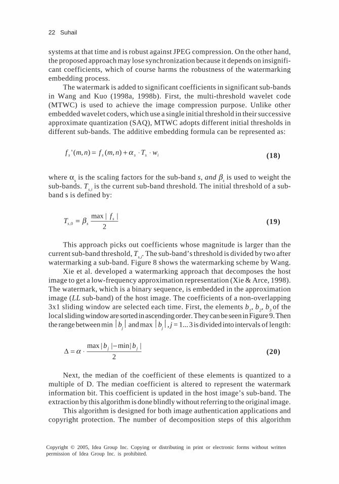
The watermark is added to significant coefficients in significant sub-bandsin Wang and Kuo (1998a, 1998b). First, the multi-threshold wavelet code(MTWC) is used to achieve the image compression purpose. Unlike otherembedded wavelet coders, which use a single initial threshold in their successiveapproximate quantization (SAQ), MTWC adopts different initial thresholds indifferent sub-bands. The additive embedding formula can be represented as:
issss wTnmfnmf ⋅⋅+= α),(),(' (18)
where αs is the scaling factors for the sub-band s, and β
s is used to weight the
sub-bands. Ts,i
is the current sub-band threshold. The initial threshold of a sub-band s is defined by:
2
||max0,
sss
fT β= (19)
This approach picks out coefficients whose magnitude is larger than thecurrent sub-band threshold, T
s,i. The sub-band’s threshold is divided by two after
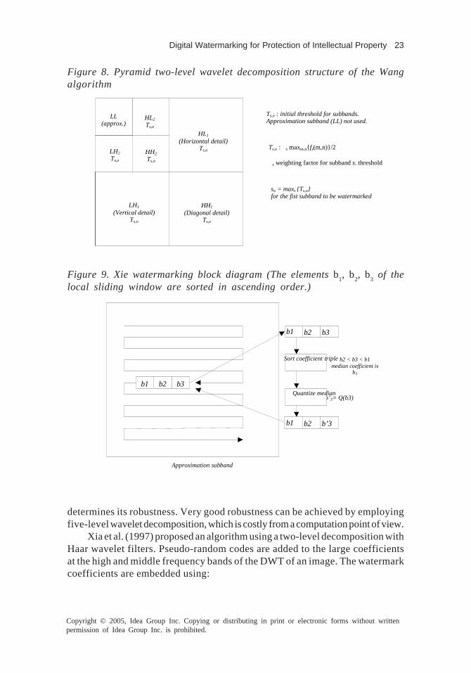
watermarking a sub-band. Figure 8 shows the watermarking scheme by Wang.Xie et al. developed a watermarking approach that decomposes the host
image to get a low-frequency approximation representation (Xie & Arce, 1998).The watermark, which is a binary sequence, is embedded in the approximationimage (LL sub-band) of the host image. The coefficients of a non-overlapping3x1 sliding window are selected each time. First, the elements b
1, b
2, b
3 of the
local sliding window are sorted in ascending order. They can be seen in Figure 9. Thenthe range between min b
j and max b
j, j = 1... 3 is divided into intervals of length:
2
||min||max jj bb −⋅=∆ α (20)
Next, the median of the coefficient of these elements is quantized to amultiple of D. The median coefficient is altered to represent the watermarkinformation bit. This coefficient is updated in the host image’s sub-band. Theextraction by this algorithm is done blindly without referring to the original image.
This algorithm is designed for both image authentication applications andcopyright protection. The number of decomposition steps of this algorithm
Digital Watermarking for Protection of Intellectual Property 23
Copyright © 2005, Idea Group Inc. Copying or distributing in print or electronic forms without writtenpermission of Idea Group Inc. is prohibited.
LL�
(approx.)
HH2
Ts,o
HH1
(Diagonal detail) Ts,o
HL1
(Horizontal detail) Ts,o
LH1
(Vertical detail) Ts,o
HL2
Ts,o
LH2
Ts,o�
Ts,o : initial threshold for subbands. Approximation subband (LL) not used.
Ts,o : s maxm,n{fs(m,n)}/2
s weighting factor for subband s. threshold
so = maxs {Ts,o} for the fist subband to be watermarked
Figure 8. Pyramid two-level wavelet decomposition structure of the Wangalgorithm
b2 < b3 < b1 median coefficient is
b3 b3
b’3= Q(b3)
Approximation subband
b3 b2 b1
Sort coefficient triple
Quantize median
b1 b2 b3
b1 b2 b’3
Figure 9. Xie watermarking block diagram (The elements b1, b
2, b
3 of the
local sliding window are sorted in ascending order.)
determines its robustness. Very good robustness can be achieved by employingfive-level wavelet decomposition, which is costly from a computation point of view.
Xia et al. (1997) proposed an algorithm using a two-level decomposition withHaar wavelet filters. Pseudo-random codes are added to the large coefficientsat the high and middle frequency bands of the DWT of an image. The watermarkcoefficients are embedded using:

24 Suhail
Copyright © 2005, Idea Group Inc. Copying or distributing in print or electronic forms without writtenpermission of Idea Group Inc. is prohibited.
iwnmfnmfnmf ⋅⋅+= βα ),(),()',( (21)
The LL sub-band does not carry any watermark information. α is theweighting or watermarking energy factor as explained before, and β indicates theamplification of large coefficients. Therefore, this algorithm merges most of thewatermarking energy in edges and texture, which represents most of thecoefficients in the detail sub-bands. This will enhance invisibility of thewatermarking process because the human eye is less sensitive to changes inedge and texture information, compared to changes in low-frequency compo-nents that are concentrated in the LL sub-band. Also, it is shown that this methodis robust to some common image distortions. However, low pass and medianfilters will affect the robustness of the algorithm since most of the watermarkingcoefficients are in the high frequency coefficients of the host signal.
Kundur and Hatzinakos proposed to apply the Daubechies family oforthogonal wavelet filters to decompose the original image to a three-level multi-resolution representation (1998). Figure 10 shows the scheme representation ofthis algorithm.
The algorithm pseudo-randomly selects locations in the detail sub-bands.The selected coefficients are sorted in ascending coefficient magnitude order.Then the median coefficient is quantized to designate the information of a singlewatermark bit. The median coefficient is set to the nearest reconstruction pointthat represents the current watermark information. The quantization step size iscontrolled by the bin width parameter ∆. The robustness of this algorithm is not
Selected coefficients at resolution level 1 (fLH,1(m,n), fHL,1(m,n), fHH,1(m,n))
Manipulating median coefficient fk2,1 (m,n)
In ascending order fk1,1(m,n)< fk2,1(m,n)< fk3,1(m,n)
LH1
4.2
HL1
15.7
HH1
0.53
LL LH2
HL2 HH2
fk2,1 (m,n)
fk3,1 (m,n) fk1,1 (m,n)
Figure 10. Scheme representation of Kundur algorithm (The algorithmpseudo-randomly selects locations in the detail subbands. The selectedcoefficients are sorted in ascending coefficient magnitude order.)

Digital Watermarking for Protection of Intellectual Property 25
Copyright © 2005, Idea Group Inc. Copying or distributing in print or electronic forms without writtenpermission of Idea Group Inc. is prohibited.
good enough; therefore, the authors suggest an improvement to the algorithm inKundur and Hatzinakos (1999). Coarser quantization in this algorithm enhancesrobustness. However, this also increases distortion in the watermarked signal.
Also, Kundur and Hatzinakos (1998) proposed a fragile watermark. Theycall such a technique a telltale tamper-proofing method. Their design embeds afragile watermark in the discrete wavelet domain of the signal by quantizing thecorresponding coefficients with user-specified keys. The watermark is a binarysignature, which is embedded into key-selected detail sub-band coefficients.This algorithm is built on the quantization method (Kundur & Hatzinakos, 1998).An integer wavelet transform is introduced to avoid round-off errors during theinverse transform, because round-off may be considered as a tampering attempt.This algorithm is just an extension of Kundur and Hatzinakos (1998); however,it is not used for copyright protection, just for tamper proofing.
Kundur and Hatzinakos also developed an algorithm for still imagewatermarking in which the watermark embedding process employs multi-resolution fusion techniques and incorporates a model of the human visual system(Kundur & Hatzinakos, 1997). The watermark in Kundur and Hatzinakos (1997)is a logo image, which is decomposed using the DWT. The watermark is chosento be a factor of 2M smaller than the host image. Both the original image and thewatermark are transformed into the DWT domain. The host image is decom-posed in L steps (L is an integer, L ≤ M). The watermark is embedded in all detailsub-bands. Kundur presented rules to select all parameters of the HVS modeland the scaling parameters. Simulation results demonstrated robustness of thealgorithm to common image distortions. The algorithm is not robust to rotation.
Podilchukand Zeng (1998) proposed two watermarking techniques fordigital images that are based on utilizing visual models, which have beendeveloped in the context of image compression. Specifically, they proposedwatermarking schemes where visual models are used to determine image-dependent upper bounds on watermark insertion. They propose perceptuallybased watermarking schemes in two frameworks: the block-based discretecosine transform and multi-resolution wavelet framework, and discuss the meritsof each one. Their schemes are shown to provide very good results both in termsof image transparency and robustness.
Chae et al. (1998a, 1998b) proposed a grayscale image, with as much as25% of the host image size to be used as a watermark. They suggested using aone-level decomposition on both the host and the logo image. Each coefficientof the original signal is modified to insert the logo image. The block diagram ofthis scheme can be seen in Figure 11. The coefficients have to be expanded dueto the size of the logo image, which is 25% of the host image. For the logo image,A, B, C stand for the most significant byte (MSB), the middle byte, and the leastsignificant byte (LSBe) respectively. A, B, C represent a 24-bits per coefficient.Three 24-bit numbers A’, B’, C’ are produced by considering A, B and C as their

26 Suhail
Copyright © 2005, Idea Group Inc. Copying or distributing in print or electronic forms without writtenpermission of Idea Group Inc. is prohibited.
most significant byte, respectively. Also, the middle and least significant bytesare set to zero. Then a block of 2x2 is built. The logo image is added to the originalimage by:
f’(m, n) = α f (m, n) + w(m, n) (22)
where f(m,n) is the DWT coefficient of the original image and the DWTcoefficients of the logo image are given by w(m, n). This algorithm is limited tologo images that are 25% of the size of the host image. Also, there is anotherconstraint. It is difficult to use higher wavelet decomposition steps since thewatermark is a logo image. Also, their experimental results show that thewatermarked image is transparent to embedding and the quality of the extractedsignature is high even when the watermarked image is subjected to waveletcompression and JPEG lossy compression. On the other hand, geometric attackswere not studied in this work. The capacity issue with this scheme can beconsidered as trade-off between the quantity of hidden data and the quality ofthe watermarked image. Murkherjee et al. (1998) and Chae et al. (1998) alsointroduced a watermark sequence w
i of p-ary symbols. Similar to the work of
Figure 11. Chae watermarking process (The coefficients have to beexpanded due to the size of the logo image, which is 25% of the host image.)
scale by add ALPHA images inverse scaling
IDWT
Host image, fused image scaled to 24 bits/coefficient
expanded block
2x2 expand DWT
Logo image Scaled to 24 bits/coefficient expanded logo
image A’
B’
MSB LSBe
24 bit logo coefficient shifted to MSB
LL LH
HL
HH LL LH
HL HH
LL LH HL HH
A’ B’ C’ A’
0 0 A
A B C B 0 0 C 0 0
DWT
C’
Digital Watermarking for Protection of Intellectual Property 27
Copyright © 2005, Idea Group Inc. Copying or distributing in print or electronic forms without writtenpermission of Idea Group Inc. is prohibited.
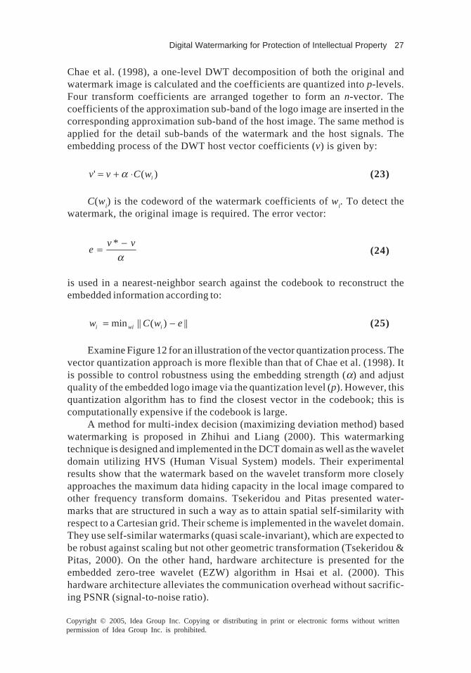
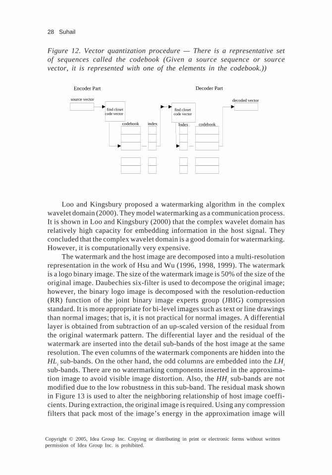
Chae et al. (1998), a one-level DWT decomposition of both the original andwatermark image is calculated and the coefficients are quantized into p-levels.Four transform coefficients are arranged together to form an n-vector. Thecoefficients of the approximation sub-band of the logo image are inserted in thecorresponding approximation sub-band of the host image. The same method isapplied for the detail sub-bands of the watermark and the host signals. Theembedding process of the DWT host vector coefficients (v) is given by:
)(' iwCvv ⋅+= α (23)
C(wi) is the codeword of the watermark coefficients of w
i. To detect the
watermark, the original image is required. The error vector:
αvv
e−
=*
(24)
is used in a nearest-neighbor search against the codebook to reconstruct theembedded information according to:
||)(||min ewCw iwii −= (25)
Examine Figure 12 for an illustration of the vector quantization process. Thevector quantization approach is more flexible than that of Chae et al. (1998). Itis possible to control robustness using the embedding strength (α) and adjustquality of the embedded logo image via the quantization level (p). However, thisquantization algorithm has to find the closest vector in the codebook; this iscomputationally expensive if the codebook is large.
A method for multi-index decision (maximizing deviation method) basedwatermarking is proposed in Zhihui and Liang (2000). This watermarkingtechnique is designed and implemented in the DCT domain as well as the waveletdomain utilizing HVS (Human Visual System) models. Their experimentalresults show that the watermark based on the wavelet transform more closelyapproaches the maximum data hiding capacity in the local image compared toother frequency transform domains. Tsekeridou and Pitas presented water-marks that are structured in such a way as to attain spatial self-similarity withrespect to a Cartesian grid. Their scheme is implemented in the wavelet domain.They use self-similar watermarks (quasi scale-invariant), which are expected tobe robust against scaling but not other geometric transformation (Tsekeridou &Pitas, 2000). On the other hand, hardware architecture is presented for theembedded zero-tree wavelet (EZW) algorithm in Hsai et al. (2000). Thishardware architecture alleviates the communication overhead without sacrific-ing PSNR (signal-to-noise ratio).
28 Suhail
Copyright © 2005, Idea Group Inc. Copying or distributing in print or electronic forms without writtenpermission of Idea Group Inc. is prohibited.
Loo and Kingsbury proposed a watermarking algorithm in the complexwavelet domain (2000). They model watermarking as a communication process.It is shown in Loo and Kingsbury (2000) that the complex wavelet domain hasrelatively high capacity for embedding information in the host signal. Theyconcluded that the complex wavelet domain is a good domain for watermarking.However, it is computationally very expensive.
The watermark and the host image are decomposed into a multi-resolutionrepresentation in the work of Hsu and Wu (1996, 1998, 1999). The watermarkis a logo binary image. The size of the watermark image is 50% of the size of theoriginal image. Daubechies six-filter is used to decompose the original image;however, the binary logo image is decomposed with the resolution-reduction(RR) function of the joint binary image experts group (JBIG) compressionstandard. It is more appropriate for bi-level images such as text or line drawingsthan normal images; that is, it is not practical for normal images. A differentiallayer is obtained from subtraction of an up-scaled version of the residual fromthe original watermark pattern. The differential layer and the residual of thewatermark are inserted into the detail sub-bands of the host image at the sameresolution. The even columns of the watermark components are hidden into theHL
i sub-bands. On the other hand, the odd columns are embedded into the LH
i
sub-bands. There are no watermarking components inserted in the approxima-tion image to avoid visible image distortion. Also, the HH
i sub-bands are not
modified due to the low robustness in this sub-band. The residual mask shownin Figure 13 is used to alter the neighboring relationship of host image coeffi-cients. During extraction, the original image is required. Using any compressionfilters that pack most of the image’s energy in the approximation image will
Figure 12. Vector quantization procedure — There is a representative setof sequences called the codebook (Given a source sequence or sourcevector, it is represented with one of the elements in the codebook.))
source vector decoded vector
codebook index Index � codebook�
find closet code vector
Encoder Part Decoder Part
find closet code vector

Digital Watermarking for Protection of Intellectual Property 29
Copyright © 2005, Idea Group Inc. Copying or distributing in print or electronic forms without writtenpermission of Idea Group Inc. is prohibited.
seriously damage the robustness of this algorithm. This is because the watermarkinformation is embedded in the detail sub-band.
Ejima and Miyazki suggested using a wavelet packet of image and videowatermarking (2000). Figure 14 depicts the wavelet packet representation usedby Ejima. The energy for each sub-band B
i,j is calculated. Then, certain sub-
bands are pseudo-randomly selected according to their energy. The meanabsolute coefficient value of each selected sub-band is quantized and used toencode one bit of watermark information. Finally, pseudo-randomly selectedcoefficients of that sub-band are manipulated to reflect the quantized coefficientmean value. This type of algorithm generates redundant information since thewavelet packet generates details and approximation sub-band for each resolu-tion, which adds to the computation overhead.
Kim et al. (1999) proposed to insert a watermark into the large coefficientsin each DWT band of L=3, except the first level sub-bands. The number ofwatermark elements w
i in each of the detail sub-bands is proportional to the
energy of that sub-band. They defined this energy by:
∑∑−
=
−
=⋅=
1
0
21
0
1 M
m
N
ns nmf
NMe ),( (26)
where M, N denotes the size of the sub-band. The watermark (wi) is also a
Gaussian sequence of pseudo-random real numbers. In the detail sub-bands,4,500 coefficients are modified but only 500 are modified in the approximationsub-band. Before inserting the watermark coefficients, the host image DWT
Pseudo- Resolution random Reduction permutation
residual scrambled residual
Watermark Image (logo)
Differential layer
LL 2 HL 2
LH 2 HH 2 HH
HL 1
LH l HH 1 Scrambled differential
layer
Figure 13. Scheme for binary watermarking embedding algorithm proposedby Hsu’s
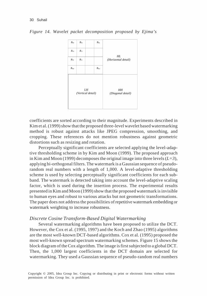
30 Suhail
Copyright © 2005, Idea Group Inc. Copying or distributing in print or electronic forms without writtenpermission of Idea Group Inc. is prohibited.
coefficients are sorted according to their magnitude. Experiments described inKim et al. (1999) show that the proposed three-level wavelet based watermarkingmethod is robust against attacks like JPEG compression, smoothing, andcropping. These references do not mention robustness against geometricdistortions such as resizing and rotation.
Perceptually significant coefficients are selected applying the level-adap-tive thresholding scheme in by Kim and Moon (1999). The proposed approachin Kim and Moon (1999) decomposes the original image into three levels (L=3),applying bi-orthogonal filters. The watermark is a Gaussian sequence of pseudo-random real numbers with a length of 1,000. A level-adaptive thresholdingscheme is used by selecting perceptually significant coefficients for each sub-band. The watermark is detected taking into account the level-adaptive scalingfactor, which is used during the insertion process. The experimental resultspresented in Kim and Moon (1999) show that the proposed watermark is invisibleto human eyes and robust to various attacks but not geometric transformations.The paper does not address the possibilities of repetitive watermark embedding orwatermark weighting to increase robustness.
Discrete Cosine Transform-Based Digital WatermarkingSeveral watermarking algorithms have been proposed to utilize the DCT.
However, the Cox et al. (1995, 1997) and the Koch and Zhao (1995) algorithmsare the most well-known DCT-based algorithms. Cox et al. (1995) proposed themost well-known spread spectrum watermarking schemes. Figure 15 shows theblock diagram of the Cox algorithm. The image is first subjected to a global DCT.Then, the 1,000 largest coefficients in the DCT domain are selected forwatermarking. They used a Gaussian sequence of pseudo-random real numbers
HH
(Diagonal detail)
HL
(Horizontal detail)
LH
(Vertical detail)
B00� B01��
B0n�
B10� B11��
�
Bm0� �
�
Bmn�
B10� B11��
�
Figure 14. Wavelet packet decomposition proposed by Ejima’s
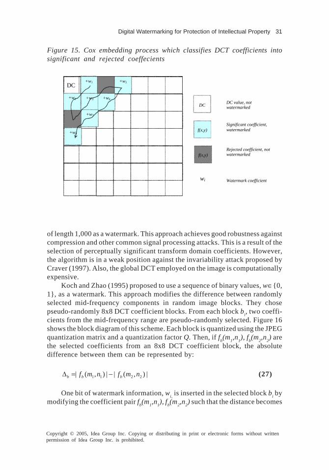
Digital Watermarking for Protection of Intellectual Property 31
Copyright © 2005, Idea Group Inc. Copying or distributing in print or electronic forms without writtenpermission of Idea Group Inc. is prohibited.
of length 1,000 as a watermark. This approach achieves good robustness againstcompression and other common signal processing attacks. This is a result of theselection of perceptually significant transform domain coefficients. However,the algorithm is in a weak position against the invariability attack proposed byCraver (1997). Also, the global DCT employed on the image is computationallyexpensive.
Koch and Zhao (1995) proposed to use a sequence of binary values, w∈{0,1}, as a watermark. This approach modifies the difference between randomlyselected mid-frequency components in random image blocks. They chosepseudo-randomly 8x8 DCT coefficient blocks. From each block b
i, two coeffi-
cients from the mid-frequency range are pseudo-randomly selected. Figure 16shows the block diagram of this scheme. Each block is quantized using the JPEGquantization matrix and a quantization factor Q. Then, if f
b(m
1,n
1), f
b(m
2,n
2) are
the selected coefficients from an 8x8 DCT coefficient block, the absolutedifference between them can be represented by:
|),(||),(| 2211 nmfnmf bbb −=∆ (27)
One bit of watermark information, wi, is inserted in the selected block b
i by
modifying the coefficient pair fb(m
1,n
1), f
b(m
2,n
2) such that the distance becomes
DC�
+w1�
�
+w2�
+w3�
�
+w5�
+w6�
�
+w8�
+w7�
f(x,y)
�
DC
�
f(x,y)�
DC value, not watermarked�
Significant coefficient, watermarked�
Rejected coefficient, not watermarked
�
wi� Watermark coefficient�
Figure 15. Cox embedding process which classifies DCT coefficients intosignificant and rejected coeffecients
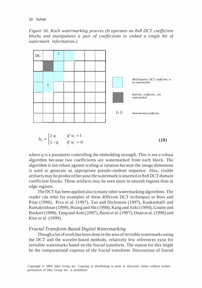
32 Suhail
Copyright © 2005, Idea Group Inc. Copying or distributing in print or electronic forms without writtenpermission of Idea Group Inc. is prohibited.
=−≤=≥
=∆0
1
i
ib wifq
wifq(28)
where q is a parameter controlling the embedding strength. This is not a robustalgorithm because two coefficients are watermarked from each block. Thealgorithm is not robust against scaling or rotation because the image dimensionis used to generate an appropriate pseudo-random sequence. Also, visibleartifacts may be produced because the watermark is inserted in 8x8 DCT domaincoefficient blocks. These artifacts may be seen more in smooth regions than inedge regions.
The DCT has been applied also in many other watermarking algorithms. Thereader can refer for examples of these different DCT techniques to Bors andPitas (1996), Piva et al. (1997), Tao and Dickinson (1997), Kankanhalli andRamakrishnan (1999), Huang and Shi (1998), Kang and Aoki (1999), Goutte andBaskurt (1998), Tang and Aoki (1997), Barni et al. (1997), Duan et al. (1998) andKim et al. (1999).
Fractal Transform-Based Digital WatermarkingThough a lot of work has been done in the area of invisible watermarks using
the DCT and the wavelet-based methods, relatively few references exist forinvisible watermarks based on the fractal transform. The reason for this mightbe the computational expense of the fractal transform. Discussions of fractal
DC�
�
�
Mid-frequency DCT coefficient, to be watermarked�
Rejected coefficient, not watermarked�
f1, f2� Watermarked coefficient�
f2�
�
�
f2�
�
�
f2�
�
�
�
Figure 16. Koch watermarking process (It operates on 8x8 DCT coefficientblocks and manipulates a pair of coefficients to embed a single bit ofwatermark information.)
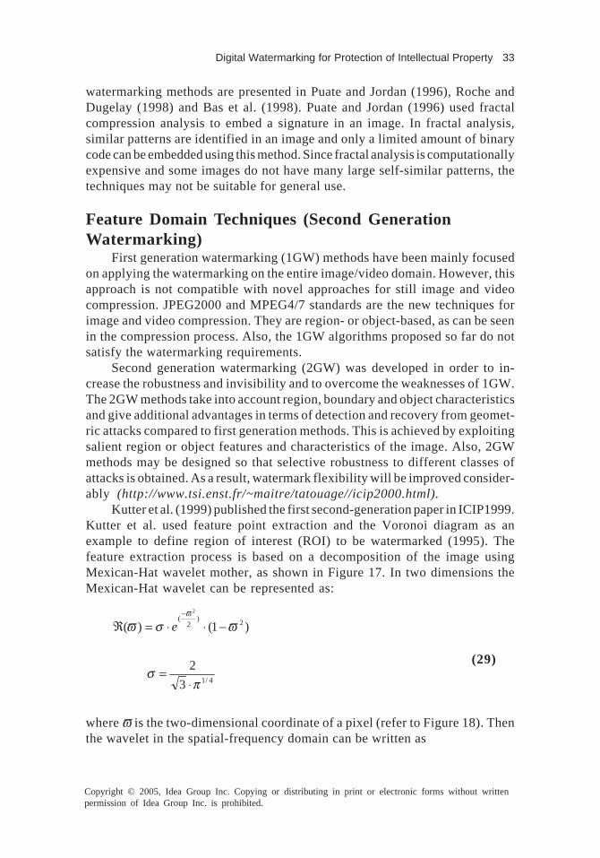
Digital Watermarking for Protection of Intellectual Property 33
Copyright © 2005, Idea Group Inc. Copying or distributing in print or electronic forms without writtenpermission of Idea Group Inc. is prohibited.
watermarking methods are presented in Puate and Jordan (1996), Roche andDugelay (1998) and Bas et al. (1998). Puate and Jordan (1996) used fractalcompression analysis to embed a signature in an image. In fractal analysis,similar patterns are identified in an image and only a limited amount of binarycode can be embedded using this method. Since fractal analysis is computationallyexpensive and some images do not have many large self-similar patterns, thetechniques may not be suitable for general use.
Feature Domain Techniques (Second GenerationWatermarking)
First generation watermarking (1GW) methods have been mainly focusedon applying the watermarking on the entire image/video domain. However, thisapproach is not compatible with novel approaches for still image and videocompression. JPEG2000 and MPEG4/7 standards are the new techniques forimage and video compression. They are region- or object-based, as can be seenin the compression process. Also, the 1GW algorithms proposed so far do notsatisfy the watermarking requirements.
Second generation watermarking (2GW) was developed in order to in-crease the robustness and invisibility and to overcome the weaknesses of 1GW.The 2GW methods take into account region, boundary and object characteristicsand give additional advantages in terms of detection and recovery from geomet-ric attacks compared to first generation methods. This is achieved by exploitingsalient region or object features and characteristics of the image. Also, 2GWmethods may be designed so that selective robustness to different classes ofattacks is obtained. As a result, watermark flexibility will be improved consider-ably (http://www.tsi.enst.fr/~maitre/tatouage//icip2000.html).
Kutter et al. (1999) published the first second-generation paper in ICIP1999.Kutter et al. used feature point extraction and the Voronoi diagram as anexample to define region of interest (ROI) to be watermarked (1995). Thefeature extraction process is based on a decomposition of the image usingMexican-Hat wavelet mother, as shown in Figure 17. In two dimensions theMexican-Hat wavelet can be represented as:
4/1
2)2
(
3
2
)1()(
2
πσ
ϖσϖϖ
⋅=
−⋅⋅=ℜ−
e
(29)
where ϖ is the two-dimensional coordinate of a pixel (refer to Figure 18). Thenthe wavelet in the spatial-frequency domain can be written as

34 Suhail
Copyright © 2005, Idea Group Inc. Copying or distributing in print or electronic forms without writtenpermission of Idea Group Inc. is prohibited.
)/(1)()( kkH ekkk
�����⋅−
∧⋅⋅=ℜ (30)
where k�
is the 2D spatial-frequency variable. The Mexican Hat is alwayscentered at the origin in the frequency domain, which means that the responseof a Mexican Hat wavelet is invariant to rotation. However, the stability of themethod proposed in Kutter’s work depends on the features points. Theseextracted features have the drawback that their location may change by somepixels because of attack or during the watermarking process. Changing thelocation of the extracted feature points will cause problems during the detectingprocess.
Later in 2000, ICIP organized a special session on second-generation digitalwatermarking algorithms (Baudry et al., 2000; Eggers et al., 2000; Furon &Duhamel, 2000; Loo & Kingsbury, 2000; Lu & Liao, 2000; Miller et al., 2000;Piva et al., 2000; Solachidis et al., 2000). Eight papers were presented in thissession. This special session was intended to provide researchers with theopportunity of presenting the latest research results on second-generation digitalwatermarking Kutter et al. (1999) show that rather than looking at the image
����
����
����
���
���
���
���
���
���
� �� �
Figure 17. Mexican-hat mother wavelet function for 1D
Figure 18. 2D Mexican-hat mother wavelet function in spatial domain (left)and in transform domain (right)
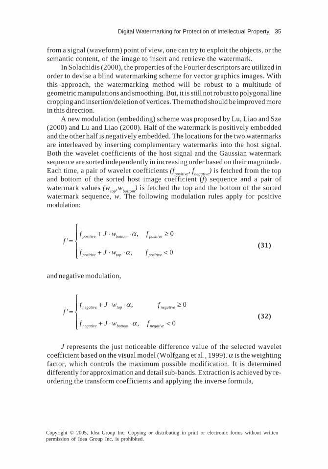
Digital Watermarking for Protection of Intellectual Property 35
Copyright © 2005, Idea Group Inc. Copying or distributing in print or electronic forms without writtenpermission of Idea Group Inc. is prohibited.
from a signal (waveform) point of view, one can try to exploit the objects, or thesemantic content, of the image to insert and retrieve the watermark.
In Solachidis (2000), the properties of the Fourier descriptors are utilized inorder to devise a blind watermarking scheme for vector graphics images. Withthis approach, the watermarking method will be robust to a multitude ofgeometric manipulations and smoothing. But, it is still not robust to polygonal linecropping and insertion/deletion of vertices. The method should be improved morein this direction.
A new modulation (embedding) scheme was proposed by Lu, Liao and Sze(2000) and Lu and Liao (2000). Half of the watermark is positively embeddedand the other half is negatively embedded. The locations for the two watermarksare interleaved by inserting complementary watermarks into the host signal.Both the wavelet coefficients of the host signal and the Gaussian watermarksequence are sorted independently in increasing order based on their magnitude.Each time, a pair of wavelet coefficients (f
positive, f
negative) is fetched from the top
and bottom of the sorted host image coefficient (f) sequence and a pair ofwatermark values (w
top,w
bottom) is fetched the top and the bottom of the sorted
watermark sequence, w. The following modulation rules apply for positivemodulation:
<⋅⋅+
≥⋅⋅+=
0,
0,'
positivetoppositive
positivebottompositive
fwJf
fwJff
α
α(31)
and negative modulation,
<⋅⋅+
≥⋅⋅+=
0,
0,'
negativebottomnegative
negativetopnegative
fwJf
fwJff
α
α(32)
J represents the just noticeable difference value of the selected waveletcoefficient based on the visual model (Wolfgang et al., 1999). α is the weightingfactor, which controls the maximum possible modification. It is determineddifferently for approximation and detail sub-bands. Extraction is achieved by re-ordering the transform coefficients and applying the inverse formula,

36 Suhail
Copyright © 2005, Idea Group Inc. Copying or distributing in print or electronic forms without writtenpermission of Idea Group Inc. is prohibited.
α−−=
J
ffw
** (33)
This proposed complementary modulation approach can be applied to allspread spectrum watermarking algorithms in other domains. It performs betterthan random insertion because modulation of one of the two marks will besignificantly stronger after attack by simultaneously embedding two complimen-tary watermarks. Security issues and geometric attacks were not considered inthe design of this algorithm. Also, Lu and Liao (2000) used the same approachto propose a semi-blind watermark extraction. The original image is not requiredat the detection side; only a set of image-dependent parameters is needed. Theseparameters describe the wavelet coefficient probability distribution that origi-nally has been embedded. The host image coefficient selection is limited to detailsub-bands because only the high frequency bands can be accurately modeledusing this approach. More research should focus on the analysis of accuracy ofindependent component analysis (ICA). This is because ICA is used torepresent the host image in this work. Also, the accuracy of automaticsegmentation is one of the drawbacks of this method.
Piva et al. proposed a method for a DWT-based object watermarkingsystem for MPEG-4 video streams. Their method relies on an image-watermarkingalgorithm, which embeds the code in the discrete wavelet transform of eachframe. They insert the watermark before compression, that is, frame by frame,for this to be robust against format conversions. However, analysis of theproposed system against a larger set of attacks is not considered in Piva et al.(2000).
The host image is decomposed using the dual tree complex-wavelettransform (DT-CWT) to obtain a three-level multi-resolution representation inLoo and Kingsbury (2000). The mark is a bipolar, w
i∈{–1, 1} pseudo-random
bitmap. The 1,000 largest coefficients in the DCT domain are selected in a similarmanner to the Cox et al. algorithm (1997). However, the embedding is done inthe wavelet transform domain. The watermark coefficient is inserted accordingto:
iwnmnmfnmf ⋅+⋅+= 22),(),(),(' βζα (34)
where α and β are level-dependent weights. ζ(m,n) is the average magnitude ina 3x3 neighborhood around the coefficient location. The DT-CWT has a 4:1redundancy for 2D signals. The proposed transform overcomes two drawbacksof the DWT. These are directional selectivity of diagonal features and lack ofshift invariance. Real DWT filters do not capture the direction of diagonalfeatures. As a result of that, the local image activity is not optimally represented,

Digital Watermarking for Protection of Intellectual Property 37
Copyright © 2005, Idea Group Inc. Copying or distributing in print or electronic forms without writtenpermission of Idea Group Inc. is prohibited.
also limiting the energy of the signal that can be embedded imperceptibly. Shiftinvariance means that small shifts in the input signal do not cause major variationsin the distribution of energy between wavelet coefficients at different scales. Onthe other hand, due to the redundancy in the transform domain, some embeddedinformation might be lost in the inverse transform process or during imagecompression, which affects the robustness of the algorithm.
Comments on the Existing AlgorithmsFrom the literature review in this section, it is apparent that digital watermarking
can be achieved by using either transform techniques and embedding thewatermark data into the frequency domain representation of the host image orby directly embedding the watermark into the spatial domain data of the image.The review also shows there are several requirements that the embeddingmethod has yet to satisfy. Creating robust watermarking methods is still achallenging research problem. These algorithms are robust against some attacksbut not against most of them. As an example, they cannot withstand geometricattacks such as rotation or cropping. Also, some of the current methods aredesigned to suit only specific application, which limits their widespread use.
Moreover, there are drawbacks in the existing algorithms associated withthe watermark-embedding domain. These drawbacks vary from system tosystem. Watermarking schemes that modify the LSB of the data using a fixedmagnitude PN sequence are highly sensitive to signal processing operations andare easily corrupted. Some transform domain watermarking algorithms cannotsurvive most image processing operations and geometric manipulations. This willlimit their use in large numbers of applications. Using fractal transforms, only alimited amount of binary code can be embedded. Since fractal analysis iscomputationally expensive, and some images do not have many large, self-similarpatterns, fractal-based algorithms may not be suitable or practical for generaluse. Feature domain algorithms suffer from problems of stability of featurepoints if they are exposed to an attack. For example, the method proposed inKutter’s work depends on the stability of extracted features whose locationsmay change by several pixels because of attack or because of the watermarkingprocess. This will cause problems during the decoding process. Security is anissue facing most of the algorithms reviewed.
FUTURE OF DIGITAL WATERMARKINGWatermarking technology is still in the evolutionary stages. The watermarking
future is promising. While the challenges to realization of this dream are many,a great deal of research effort has already been expended to overcome thesechallenges. Therefore, the objective of this section is to shed light on importantaspects of the future of watermarking technology.

38 Suhail
Copyright © 2005, Idea Group Inc. Copying or distributing in print or electronic forms without writtenpermission of Idea Group Inc. is prohibited.
Development ChallengesWatermarking technology will become increasingly important as more
vendors wish to sell their digital works on the Internet. This includes all mannersof digital data including books, images, music and movies. Progress has beenmade and lots of developments and improvements have happened in the lastseven years. However, despite this development and improvement in the digitalimage watermarking field, current technologies are far from what the end useris expecting. Lack of standardization and lack of a set of precise and realisticrequirements for watermarking systems are two aspects that hinder furtherdevelopments of digital watermarking techniques and copy protection mecha-nisms. Also, the lack of agreement on the definition of a common benchmark formethod comparison and on the definition of the performance related concept isthe third aspect for this hindering.
Digital Watermarking and Image Processing AttacksDigital watermarking was claimed to be the ultimate solution for copyright
protection over the Internet when the concept of digital watermarking was firstpresented. However, some problems related to robustness and security ofwatermarking algorithms to intentional or unintentional attacks still remainunsolved. These problems must be solved before digital watermarking can beclaimed to be the ultimate solution for copyright ownership protection in digitalmedia. One of these problems is the effect of geometrical transformations suchas rotation, translation and scaling on the recovery of the watermark. Anotheris the security of the watermarking algorithm when intentional attackers makeuse of knowledge of the watermarking algorithm to destroy or remove thewatermark.
Watermarking Standardization IssueThe most important question about watermarking technology is whether
watermarking will be standardized and used in the near future. There are severalmovements to standardize watermarking technology, but no one standard hasprevailed at this moment in time. Some researchers have been working todevelop a standardized framework for protecting digital images and othermultimedia content through technology built into media files and correspondingapplication software. However, they have lacked a clear vision of what theframework should be or how it would be used.
In addition, there was a discussion about how and whether watermarkingshould form part of the standard during the standardization process of JPEG2000.The requirements regarding security have been identified in the framework ofJPEG2000. However, there has been neither in-depth clarification nor a harmo-nized effort to address watermarking issues. It is important to deduce what really
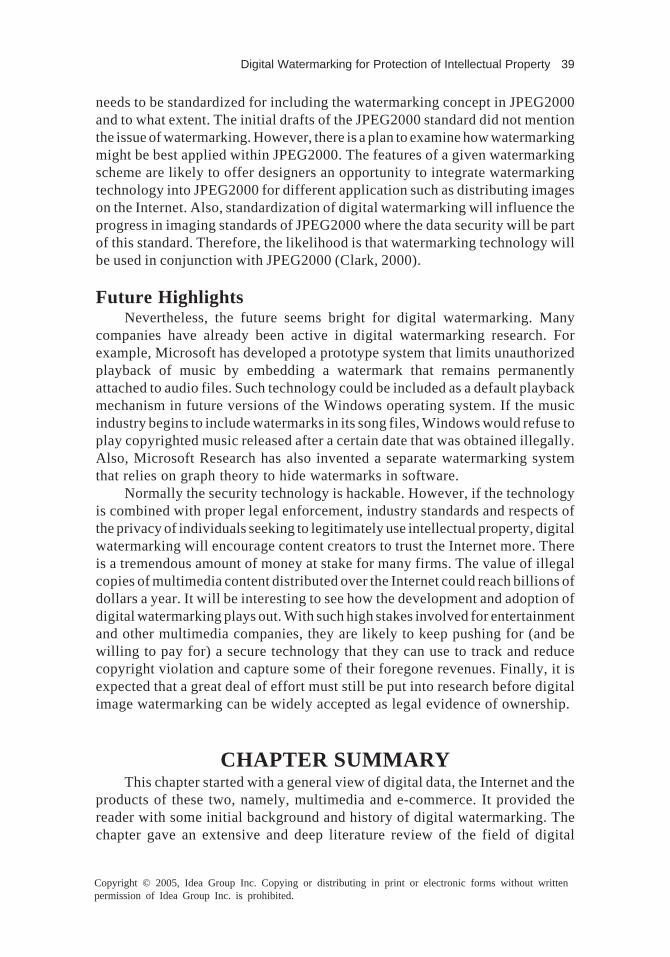
Digital Watermarking for Protection of Intellectual Property 39
Copyright © 2005, Idea Group Inc. Copying or distributing in print or electronic forms without writtenpermission of Idea Group Inc. is prohibited.
needs to be standardized for including the watermarking concept in JPEG2000and to what extent. The initial drafts of the JPEG2000 standard did not mentionthe issue of watermarking. However, there is a plan to examine how watermarkingmight be best applied within JPEG2000. The features of a given watermarkingscheme are likely to offer designers an opportunity to integrate watermarkingtechnology into JPEG2000 for different application such as distributing imageson the Internet. Also, standardization of digital watermarking will influence theprogress in imaging standards of JPEG2000 where the data security will be partof this standard. Therefore, the likelihood is that watermarking technology willbe used in conjunction with JPEG2000 (Clark, 2000).
Future HighlightsNevertheless, the future seems bright for digital watermarking. Many
companies have already been active in digital watermarking research. Forexample, Microsoft has developed a prototype system that limits unauthorizedplayback of music by embedding a watermark that remains permanentlyattached to audio files. Such technology could be included as a default playbackmechanism in future versions of the Windows operating system. If the musicindustry begins to include watermarks in its song files, Windows would refuse toplay copyrighted music released after a certain date that was obtained illegally.Also, Microsoft Research has also invented a separate watermarking systemthat relies on graph theory to hide watermarks in software.
Normally the security technology is hackable. However, if the technologyis combined with proper legal enforcement, industry standards and respects ofthe privacy of individuals seeking to legitimately use intellectual property, digitalwatermarking will encourage content creators to trust the Internet more. Thereis a tremendous amount of money at stake for many firms. The value of illegalcopies of multimedia content distributed over the Internet could reach billions ofdollars a year. It will be interesting to see how the development and adoption ofdigital watermarking plays out. With such high stakes involved for entertainmentand other multimedia companies, they are likely to keep pushing for (and bewilling to pay for) a secure technology that they can use to track and reducecopyright violation and capture some of their foregone revenues. Finally, it isexpected that a great deal of effort must still be put into research before digitalimage watermarking can be widely accepted as legal evidence of ownership.
CHAPTER SUMMARYThis chapter started with a general view of digital data, the Internet and the
products of these two, namely, multimedia and e-commerce. It provided thereader with some initial background and history of digital watermarking. Thechapter gave an extensive and deep literature review of the field of digital
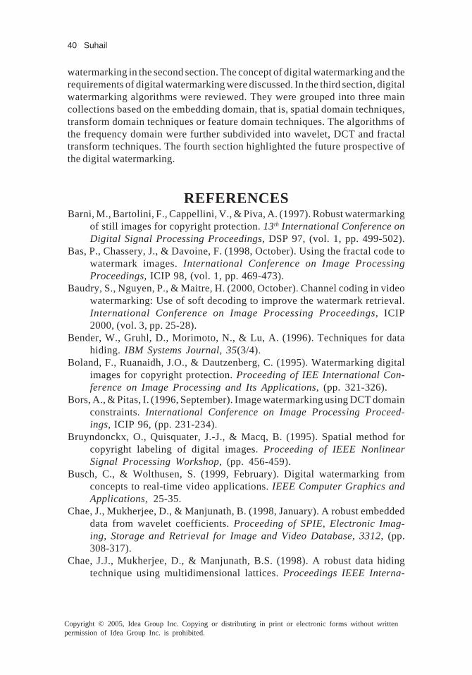
40 Suhail
Copyright © 2005, Idea Group Inc. Copying or distributing in print or electronic forms without writtenpermission of Idea Group Inc. is prohibited.
watermarking in the second section. The concept of digital watermarking and therequirements of digital watermarking were discussed. In the third section, digitalwatermarking algorithms were reviewed. They were grouped into three maincollections based on the embedding domain, that is, spatial domain techniques,transform domain techniques or feature domain techniques. The algorithms ofthe frequency domain were further subdivided into wavelet, DCT and fractaltransform techniques. The fourth section highlighted the future prospective ofthe digital watermarking.
REFERENCESBarni, M., Bartolini, F., Cappellini, V., & Piva, A. (1997). Robust watermarking
of still images for copyright protection. 13th International Conference onDigital Signal Processing Proceedings, DSP 97, (vol. 1, pp. 499-502).
Bas, P., Chassery, J., & Davoine, F. (1998, October). Using the fractal code towatermark images. International Conference on Image ProcessingProceedings, ICIP 98, (vol. 1, pp. 469-473).
Baudry, S., Nguyen, P., & Maitre, H. (2000, October). Channel coding in videowatermarking: Use of soft decoding to improve the watermark retrieval.International Conference on Image Processing Proceedings, ICIP2000, (vol. 3, pp. 25-28).
Bender, W., Gruhl, D., Morimoto, N., & Lu, A. (1996). Techniques for datahiding. IBM Systems Journal, 35(3/4).
Boland, F., Ruanaidh, J.O., & Dautzenberg, C. (1995). Watermarking digitalimages for copyright protection. Proceeding of IEE International Con-ference on Image Processing and Its Applications, (pp. 321-326).
Bors, A., & Pitas, I. (1996, September). Image watermarking using DCT domainconstraints. International Conference on Image Processing Proceed-ings, ICIP 96, (pp. 231-234).
Bruyndonckx, O., Quisquater, J.-J., & Macq, B. (1995). Spatial method forcopyright labeling of digital images. Proceeding of IEEE NonlinearSignal Processing Workshop, (pp. 456-459).
Busch, C., & Wolthusen, S. (1999, February). Digital watermarking fromconcepts to real-time video applications. IEEE Computer Graphics andApplications, 25-35.
Chae, J., Mukherjee, D., & Manjunath, B. (1998, January). A robust embeddeddata from wavelet coefficients. Proceeding of SPIE, Electronic Imag-ing, Storage and Retrieval for Image and Video Database, 3312, (pp.308-317).
Chae, J.J., Mukherjee, D., & Manjunath, B.S. (1998). A robust data hidingtechnique using multidimensional lattices. Proceedings IEEE Interna-

Digital Watermarking for Protection of Intellectual Property 41
Copyright © 2005, Idea Group Inc. Copying or distributing in print or electronic forms without writtenpermission of Idea Group Inc. is prohibited.
tional Forum on Research and Technology Advances in Digital Li-braries, ADL 98, (pp. 319-326).
Clark, R. (2000). An introduction to JPEG 2000 and watermarking. IEE Seminaron Secure Images & Image Authentication, 3/1-3/6.
Cox, I., & Miller, L. (1997, February). A review of watermarking and theimportance of perceptual modeling. Proceeding of SPIE Conference onHuman Vision and Electronic Imaging II, 3016, (pp. 92-99).
Cox, I., Kilian, J., Leighton, F.T., & Shamoon, T. (1995). Secure spreadspectrum watermarking for multimedia. Technical Report 95-10, NECResearch Institute.
Cox, I., Kilian, J., Leighton, F.T., & Shamoon, T. (1996, September). Securespread spectrum watermarking for images, audio and video. InternationalConference on Image Processing Proceedings, ICIP 96, (vol. 3, pp. 243-246).
Cox, I., Kilian, J., Leighton, F.T., & Shamoon, T. (1997, December). Securespread spectrum watermarking for multimedia. IEEE Transaction ImageProcessing, 6(12), 1673-1687.
Craver, S., Memon, N., Yeo, B., & Yeung, M. (1997, October). On theinvertibility of invisible watermarking techniques. International Confer-ence on Image Processing Proceedings, ICIP 97, (pp. 540-543).
Duan, F., King, I., Chan, L., & Xu, L. (1998). Intra-block algorithm for digitalwatermarking. 14th International Conference on Pattern RecognitionProceedings, (vol. 2, pp. 1589-1591).
Dugad, R., Ratakonda, K., & Ahuja, N. (1998, October). A new wavelet-basedscheme for watermarking images. International Conference on ImageProcessing Proceedings, ICIP 98, (vol. 2, pp. 419-423).
Eggers, J., Su, J., & Girod, B. (2000, October). Robustness of a blind imagewatermarking scheme. International Conference on Image ProcessingProceedings, ICIP 2000, (vol. 3, pp. 17-20).
Ejim, M., & Miyazaki, A. (2000, October). A wavelet-based watermarking fordigital images and video. International Conference on Image Process-ing, ICIP 00, (vol. 3, pp. 678-681).
Furon, T., & Duhamel, P. (2000, October). Robustness of asymmetricwatermarking technique. International Conference on Image Process-ing Proceedings, ICIP 2000, (vol. 3, pp. 21-24).
Goutte, R., & Baskurt, A. (1998). On a new approach of insertion of confidentialdigital signature into images. Proceedings of Fourth InternationalConference on Signal Processing, ICSP 98, (vol. 2, pp. 1170-1173).
Hartung, F., & Girod, B. (1996, October). Digital watermarking of raw andcompressed video. Proceeding of the SPIE Digital Computing Tech-niques and Systems for Video Communication, 2952, (pp. 205-213).
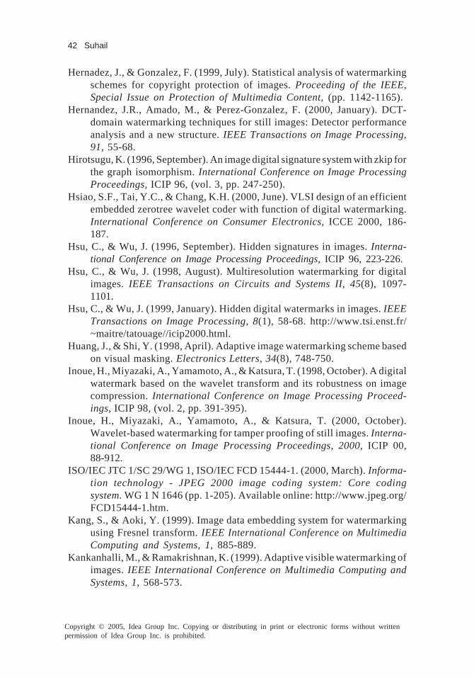
42 Suhail
Copyright © 2005, Idea Group Inc. Copying or distributing in print or electronic forms without writtenpermission of Idea Group Inc. is prohibited.
Hernadez, J., & Gonzalez, F. (1999, July). Statistical analysis of watermarkingschemes for copyright protection of images. Proceeding of the IEEE,Special Issue on Protection of Multimedia Content, (pp. 1142-1165).
Hernandez, J.R., Amado, M., & Perez-Gonzalez, F. (2000, January). DCT-domain watermarking techniques for still images: Detector performanceanalysis and a new structure. IEEE Transactions on Image Processing,91, 55-68.
Hirotsugu, K. (1996, September). An image digital signature system with zkip forthe graph isomorphism. International Conference on Image ProcessingProceedings, ICIP 96, (vol. 3, pp. 247-250).
Hsiao, S.F., Tai, Y.C., & Chang, K.H. (2000, June). VLSI design of an efficientembedded zerotree wavelet coder with function of digital watermarking.International Conference on Consumer Electronics, ICCE 2000, 186-187.
Hsu, C., & Wu, J. (1996, September). Hidden signatures in images. Interna-tional Conference on Image Processing Proceedings, ICIP 96, 223-226.
Hsu, C., & Wu, J. (1998, August). Multiresolution watermarking for digitalimages. IEEE Transactions on Circuits and Systems II, 45(8), 1097-1101.
Hsu, C., & Wu, J. (1999, January). Hidden digital watermarks in images. IEEETransactions on Image Processing, 8(1), 58-68. http://www.tsi.enst.fr/~maitre/tatouage//icip2000.html.
Huang, J., & Shi, Y. (1998, April). Adaptive image watermarking scheme basedon visual masking. Electronics Letters, 34(8), 748-750.
Inoue, H., Miyazaki, A., Yamamoto, A., & Katsura, T. (1998, October). A digitalwatermark based on the wavelet transform and its robustness on imagecompression. International Conference on Image Processing Proceed-ings, ICIP 98, (vol. 2, pp. 391-395).
Inoue, H., Miyazaki, A., Yamamoto, A., & Katsura, T. (2000, October).Wavelet-based watermarking for tamper proofing of still images. Interna-tional Conference on Image Processing Proceedings, 2000, ICIP 00,88-912.
ISO/IEC JTC 1/SC 29/WG 1, ISO/IEC FCD 15444-1. (2000, March). Informa-tion technology - JPEG 2000 image coding system: Core codingsystem. WG 1 N 1646 (pp. 1-205). Available online: http://www.jpeg.org/FCD15444-1.htm.
Kang, S., & Aoki, Y. (1999). Image data embedding system for watermarkingusing Fresnel transform. IEEE International Conference on MultimediaComputing and Systems, 1, 885-889.
Kankanhalli, M., & Ramakrishnan, K. (1999). Adaptive visible watermarking ofimages. IEEE International Conference on Multimedia Computing andSystems, 1, 568-573.
Digital Watermarking for Protection of Intellectual Property 43
Copyright © 2005, Idea Group Inc. Copying or distributing in print or electronic forms without writtenpermission of Idea Group Inc. is prohibited.
Kim, J.R., & Moon, Y.S. (1999, October). A robust wavelet-based digitalwatermarking using level-adaptive thresholding. International Confer-ence on Image Processing Proceedings, ICIP 99, 2, 226-230.
Kim, S., Suthaharan, S., Lee, H., & Rao, K. (1999). Image watermarkingscheme using visual model and BN distribution. Electronics Letters, 35(3),212-214.
Kim, Y.S., Kwon, O.H., & Park, R.H. (1999, March). Wavelet basedwatermarking method for digital images using the human visual system.Electronics Letters, 35(6), 466-468.
Koch, E., & Zhao, J. (1995). Towards robust and hidden image copyrightlabeling. Proceeding of IEEE Nonlinear Signal Processing Workshop,(pp. 452-455).
Kreyszic, E. (1998). Advanced engineering mathematics. New York: JohnWiley & Sons.
Kundur, D., & Hatzinakos, D. (1997, September). A robust digital imagewatermarking method using wavelet-based fusion. International Confer-ence on Image Processing Proceedings, ICIP 97, (vol. 1, pp. 544-547).
Kundur, D., & Hatzinakos, D. (1998a). Digital watermarking using multiresolutionwavelet decomposition. International Conference on Acoustics, Speechand Signal Processing Proceedings, (vol. 5, pp. 2969-2972).
Kundur, D., & Hatzinakos, D. (1998b, October). Towards a telltale watermarkingtechnique for tamper-proofing. International Conference on ImageProcessing Proceedings, ICIP 98, (vol. 2, pp. 409-413).
Kundur, D., & Hatzinakos, D. (1999, October). Attack characterization foreffective watermarking. International Conference on Image Process-ing Proceedings, ICIP 99, (vol. 2, pp. 240-244).
Kutter, M., Bhattacharjee, S.K., & Ebrahimi, T. (1999, October). Towardssecond generation watermarking schemes. International Conference onImage Processing Proceedings, ICIP 99, (vol. 1, pp. 320-323).
Lewis, A., & Knwles, G. (1992, April). Image compression using 2-D wavelettransform. IEEE Transactions on Image Processing, 1, 244-250.
Loo, P., & Kingsbury, N. (2000a, April). Digital watermarking with complexwavelets. IEE Seminar on Secure Images and Image Authentication,10/1-10/7.
Loo, P., & Kingsbury, N. (2000b, October). Digital watermarking using complexwavelets. International Conference on Image Processing Proceed-ings, ICIP 2000, 3, 29-32.
Lu, C.S., & Liao, H.Y. (2000, October). Oblivious cocktail watermarking bysparse code shrinkage: A regional- and global-based scheme. Interna-tional Conference on Image Processing Proceedings, ICIP 2000, 3, 13-16.

44 Suhail
Copyright © 2005, Idea Group Inc. Copying or distributing in print or electronic forms without writtenpermission of Idea Group Inc. is prohibited.
Lu, C.S., Liao, H.Y., & Sze, C.J. (2000, July). Combined watermarking forimage authentication and protection. IEEE International Conference onMultimedia and Expo, ICME 2000, 3, 1415-1418.
Lumini, A., & Maio, D. (2000, March). A wavelet-based image watermarkingscheme. International Conference on Information Technology: Cod-ing and Computing, 122-127.
Miller, M., Cox, I., & Bloom, J. (2000, October). Informed embedding exploitingimage and detector information during watermark insertion. InternationalConference on Image Processing Proceedings, ICIP 2000, 3, 1-4.
Mintzer, F., Braudaway, G.W., & Yeung, M.M. (1997, October). Effective andineffective digital watermarks. International Conference on ImageProcessing Proceedings, ICIP 97, 3, 9-12.
Mukherjee, D., Chae, J.J., & Mitra, S.K. (1998, October). A source and channelcoding approach to data hiding with application to hiding speech in video.International Conference on Image Processing Proceedings, ICIP 98,1, 348-352.
Nikolaidis, N., & Pitas, I. (1996, May). Copyright protection of images usingrobust digital signatures. Proceeding of IEEE Conference Acoustics,Speech & Signal Processing ’96, (pp. 2168-2171).
Petitcolas, F. Weakness of existing watermarking schemes. Available online:http://www.cl.cam.ac.uk/~fabb2/watermarking.
Pitas, I. (1996, September). A method for signature casting on digital images.International Conference on Image Processing Proceedings, ICIP 96,(vol. 3, pp. 215-218).
Pitas, I., & Kaskalis, T. (1995). Applying signatures on digital images. Proceed-ing of IEEE Nonlinear Signal Processing Workshop, (pp. 460-463).
Piva, A., Barni, M., Bartolini, F., & Cappellini, V. (1997, September). DCT-based watermark recovering without resorting to the uncorrupted originalimage. International Conference on Image Processing Proceedings,ICIP 97, (pp. 520-523).
Piva, A., Caldelli, R., & De Rosa, A. (2000, October). A DWT-based objectwatermarking system for MPEG-4 video streams. International Confer-ence on Image Processing Proceedings, ICIP 2000, (vol. 3, pp. 5-8).
Podilchuk, C.I., & Zeng, C.W. (1998, May). Image-adaptive watermarkingusing visual models. IEEE Journal on Selected Areas in Communica-tions, 16(4), 525-539.
Puate, J., & Jordan, F. (1996, November). Using fractal compression scheme toembed a digital signature into an image. Proceedings of SPIE PhotonicsEast’96 Symposium. Available online: http://iswww.epfl.ch/~jordan/watremarking.html.
Roche, S., & Dugelay, J. (1998). Image watermarking based on the fractaltransform: A draft demonstration. IEEE Second Workshop on Multime-dia Signal Processing, 358–363.
Digital Watermarking for Protection of Intellectual Property 45
Copyright © 2005, Idea Group Inc. Copying or distributing in print or electronic forms without writtenpermission of Idea Group Inc. is prohibited.
Ruanaidh, J.O., Boland, F., & Dowling, W. (1996, September). Phasewatermarking of digital images. International Conference on ImageProcessing Proceedings, ICIP 96, 239-242.
Ruanaidh, J.O., Dowling, W.J., & Boland, F.M. (1996, August). Watermarkingdigital images for copyright protection. IEE Proceedings on Vision,Signal and Image Processing, 143(4), 250-256.
Ruanaidh, J.O., & Pun, T. (1997, October). Rotation, scale and translationinvariant digital image watermarking. International Conference on Im-age Processing Proceedings, ICIP 97, 1, 536-539.
Schyndel, R.G., Tirkel, A.Z., & Osborne, C.F. (1994). A digital watermark.Proceeding of IEEE International Conference on Image, (vol. 2, pp.86-90).
Servetto, S.D., Podilchuk, C.I., & Ramchandran, K. (1998, October). Capacityissues in digital image watermarking. International Conference on ImageProcessing, ICIP 98, 1, 445-449.
Silvestre, G., & Dowling, W. (1997). Image watermarking using digital commu-nication techniques. International Conference on Image Processingand its Application 1997, 1, 443-447.
Solachidis, V., Nikolaidis, N., & Pitas, I. (2000, October). Fourier descriptorswatermarking of vector graphics images. International Conference onImage Processing Proceedings, ICIP 2000, 3, 9-12.
Swanson, M., Zhu, B., & Tewfik, A. (1996, September). Transparent robustimage watermarking. International Conference on Image ProcessingProceedings, ICIP 96, pp. 211-214.
Swanson, M.D., Kobayashi, M., & Shapiro, J. (1993, December). Embeddedimage coding using zerotrees of wavelet coefficients. IEEE Transactionson Signal Processing, 41(12), 3445-3462.
Tanaka, K., Nakamura, Y., & Matsui, K. (1990). Embedding secret informationinto a dithered multi-level image. Proceeding of IEEE Military Commu-nications Conference, (pp. 216-220).
Tang, W., & Aoki, Y. (1997). A DCT-based coding of images in watermarking.Proceedings of International Conference on Information, Communi-cations and Signal Processing, ICICS97, (vol. 1, pp. 510-512).
Tao, B., & Dickinson, B. (1997). Adaptive watermarking in the DCT domain.IEEE International Conference on Acoustics, Speech, and SignalProcessing, ICASSP 97, 4, 2985-2988.
Tewfik, A.H. (1998, June). Multimedia data-embedding and watermarkingtechnologies. Proceedings of the IEEE, 86(6), 1064–1087.
Tilki, J.F., & Beex, A.A. (1996). Encoding a hidden digital signature onto anaudio signal using psychoacoustic masking. Proceeding of 7th Interna-tional Conference on Signal Processing Applications and Techniques,(pp. 476-480).
46 Suhail
Copyright © 2005, Idea Group Inc. Copying or distributing in print or electronic forms without writtenpermission of Idea Group Inc. is prohibited.
Tirkel, A., Rankin, G., Schyndel, R., Ho, W., Mee, N., & Osborne, C. (1993).Electronic watermark. Proceedings of Digital Image Computing, Tech-nology and Applications, DICTA 93, (pp. 666-673).
Tsai, M., Yu, K., & Chen, Y. (2000, February). Joint wavelet and spatialtransformation for digital watermarking. IEEE Transactions on Con-sumer Electronics, 46(1), 237.
Tsekeridou, S., & Pitas, I. (2000, May). Wavelet-based self-similar watermarkingfor still images. The IEEE International Symposium on Circuits andSystems, ISCAS 2000, 1, 220- 223.
Voyatzis, G., Nikolaidis, N., & Pitas, I. (1998, September). Digital watermarkingan overview. Proceedings EUSIPCO ’98, Rhodes, Greece.
Wang, H.J., & Kuo, C.C. (1998a). Image protection via watermarking onperceptually significant wavelet coefficients. IEEE Second Workshop onMultimedia Signal Processing, 279-284.
Wang, H.J., & Kuo, C.C. (1998b). An integrated progressive image coding andwatermark system. International Conference on Acoustics, Speechand Signal Processing Proceedings, 6, 3721-3724.
Watson, A., Yang, G., Solomom, A., & Villasenor, J. (1997). Visibility of waveletquantization noise. IEEE Transaction in Image Processing, 6, 1164-1175.
Wei, Z.H., Qin, P., & Fu, Y.Q. (1998, November). Perceptual digital watermarkof images using wavelet transform. IEEE Transactions on ConsumerElectronics, 44(4), 1267 –1272.
Wolfgang, P., & Delp, E. (1996, September). A watermark for digital images.International Conference on Image Processing Proceedings, ICIP 96,219-222.
Wolfgang, R., Podlchuk, C., & Delp, E. (1999, July). Perceptual watermarks fordigital images and video. Proceedings of IEEE Special Issue on Identi-fication and Protection of Multimedia Information, 7, 1108-1126.
Wolfgang, R.B., Podilchuk, C.I., & Delp, E.J. (1998, October). The effect ofmatching watermark and compression transforms in compressed colorimages. International Conference on Image Processing Proceedings,ICIP 98, 1, 440-444.
Wu, X., Zhu, W., Xiong, Z., & Zhang, Y. (2000, May). Object-basedmultiresolution watermarking of images and video. The 2000 IEEE Inter-national Symposium on Circuits and Systems, ISCAS 2000, 1, 212-215.
Xia, X., Boncelet, C.G., & Arce, G.R. (1997, September). A multiresolutionwatermark for digital images. International Conference on Image Pro-cessing Proceedings, ICIP 97, 1, 548-551.
Xie, L., & Arce, G.R. (1998, October). Joint wavelet compression and authen-tication watermarking. International Conference on Image ProcessingProceedings, ICIP 98, 2, 427-431.
Digital Watermarking for Protection of Intellectual Property 47
Copyright © 2005, Idea Group Inc. Copying or distributing in print or electronic forms without writtenpermission of Idea Group Inc. is prohibited.
Zaho, J. Look it’s not there. Available online: http://www.byte.com/art/9701/sec18/art1.htm.
Zeng, W., & Liu, B. (1997, October). On resolving rightful ownerships of digitalimages by invisible watermarks. International Conference on ImageProcessing Proceedings, ICIP 97, (pp. 552-555).
Zhihui, W., & Liang, X. (2000, July). An evaluation method for watermarkingtechniques. IEEE International Conference on Multimedia and Expo,ICME 2000, 1, 373-376.
Zhu, W., Xiong, Z., & Zhang, Y. (1998, October). Multiresolution watermarkingfor images and video: A unified approach. International Conference onImage Processing Proceedings, ICIP 98, 1, 465-468.
ENDNOTES1 Descendants are defined as the coefficients corresponding to the same
spatial location but at a finer scale of the same orientation in the DWT sub-bands.
48 Barni, Bartolini & De Rosa
Copyright © 2005, Idea Group Inc. Copying or distributing in print or electronic forms without writtenpermission of Idea Group Inc. is prohibited.
Chapter II
Perceptual Data Hidingin Still Images
Mauro Barni, University of Siena, Italy
Franco Bartolini, University of Florence, Italy
Alessia De Rosa, University of Florence, Italy
ABSTRACTThe idea of embedding some information within a digital media, in such away that the inserted data are intrinsically part of the media itself, hasaroused a considerable interest in different fields. One of the moreexamined issues is the possibility of hiding the highest possible amount ofinformation without affecting the visual quality of the host data. For sucha purpose, the understanding of the mechanisms underlying Human Visionis a mandatory requirement. Hence, the main phenomena regulating theHuman Visual System will be firstly discussed and their exploitation in adata hiding system will be then considered.
INTRODUCTIONIn the last 10 years, digital watermarking has received increasing attention,
since it is seen as an effective tool for copyright protection of digital data(Petitcolas, Anderson, & Kuhn, 1999), one of the most crucial problems slowingdown the diffusion of new multimedia services such as electronic commerce,

Perceptual Data Hiding in Still Images 49
Copyright © 2005, Idea Group Inc. Copying or distributing in print or electronic forms without writtenpermission of Idea Group Inc. is prohibited.
open access to digital archives, distribution of documents in digital format and soon. According to the watermarking paradigm, the protection of copyrighted datais accomplished by injecting into the data an invisible signal, that is, thewatermark, conveying information about data ownership, its provenance or anyother information that can be useful to enforce copyright laws.
Recently, the idea of embedding some information within a digital documentin such a way that the inserted data are intrinsically part of the document itselfhas been progressively applied to other purposes as well, including broadcastmonitoring, data authentication, data indexing, content labelling, hidden annota-tion, and so on.
Regardless of the specific purpose, it is general agreed that one of the mainrequirements a data hiding scheme must satisfy regards invisibility; that is, thedigital code must be embedded in an imperceptible way so that its presence doesnot affect the quality of the to-be-protected data.
As far as the embedding of a hidden signal within a host image is concerned,it is evident that the understanding of the mechanisms underlying human visionis a mandatory requirement (Cox & Miller, 1997; Tewfik & Swanson, 1997;Wolfgang, Podilchuk, & Delp, 1999). All the more that, in addition to theinvisibility constraint, many applications require that the embedded informationbe resistant against the most common image manipulations. This, in turn, calls forthe necessity of embedding a watermark whose strength is as high as possible,a task which clearly can take great advantage from the availability of an accuratemodel to describe the human visual system (HVS) behaviour. In other words, wecan say that the goal of perceptual data hiding is twofold: to better hide thewatermark, thus making it less perceivable to the eye, and to allow to the use ofthe highest possible watermark strength, thus influencing positively the perfor-mance of the data recovery step.
Many approaches have been proposed so far to model the characteristicsof the HVS and to exploit such models to improve the effectiveness of existingwatermarking systems (Podilchuk & Zeng, 1998; Wolfgang et al., 1999). Thoughall the proposed methods rely on some general knowledge about the mostimportant features of HVS, we can divide the approaches proposed so far intotheoretical (Kundur & Hatzinakos, 1997; Podilchuk & Zeng, 1998; Swanson,Zhu, & Tewfik, 1998; Wolfgang et al., 1999) and heuristic (Bartolini, Barni,Cappellini & Piva, 1998; Delaigle, Vleeschouwer, & Macq, 1998; Van Schyndel,Tirkel, & Osborne, 1994) ones. Even if a theoretically grounded approach to theproblem would be clearly preferable, heuristic algorithms sometimes providebetter results due to some problems with HVS models currently in use (Bartolini,1998; Delaigle, 1998).
In this chapter, we will first give a detailed description of the mainphenomena regulating the HVS, and we will consider the exploitation of theseconcepts in a data hiding system. Then, some limits of classical HVS models will

50 Barni, Bartolini & De Rosa
Copyright © 2005, Idea Group Inc. Copying or distributing in print or electronic forms without writtenpermission of Idea Group Inc. is prohibited.
Figure 1. Noiseless (left) and noisy (right) versions of the House image
be highlighted and some possible solutions to get around these problems pointedout. Finally, we will describe a complete mask building procedure, as a possibleexploitation of HVS characteristics for perceptual data hiding in still images.
BASICS OF HUMANVISUAL SYSTEM MODELLING
Even if the human visual system is certainly one of the most complexbiological devices far from being exactly described, each person has dailyexperience of the main phenomena that influence the ability of the HVS toperceive (or not to perceive) certain stimuli. In order to exemplify suchphenomena, it may very instructive to consider two copies of the same image, onebeing a disturbed version of the other. For instance, we can consider the twoimages depicted in Figure 1, showing, on the left, a noiseless version of the houseimage, and, on the right, a noisy version of the same image. It is readily seen that:(1) noise is not visible in high activity regions, for example, on foliage; (2) noiseis very visible in uniform areas such as the sky or the street; (3) noise is lessvisible in correspondence of edges; (4) noise is less visible in dark and brightareas.
As it can be easily experienced, the above observations do not depend onthe particular image depicted in the figure. On the contrary, they can begeneralised, thus deriving some very general rules: (1) disturbances are lessvisible in highly textured regions than in uniform areas; (2) noise is more easilyperceived around edges than in textured areas, but less easily than in flat regions;(3) the human eye is less sensitive to disturbances in dark and bright regions. Inthe last decades, several mathematical models have been developed to describethe above basic mechanisms. In the following, the main concepts underlyingthese models are presented.

Perceptual Data Hiding in Still Images 51
Copyright © 2005, Idea Group Inc. Copying or distributing in print or electronic forms without writtenpermission of Idea Group Inc. is prohibited.
Basically, a model describing the human visual perception is based on twomain concepts: the contrast sensitivity function and the contrast maskingmodel. The first concept is concerned with the sensitivity of the human eye toa sine grating stimulus; as the sensitivity of the eye depends strongly on displaybackground luminance and spatial frequency of the stimulus, these two param-eters have to be taken into account in the mathematical description of humansensitivity. The second concept considers the effect of one stimulus on thedetectability of another, where the stimuli can be coincident (iso-frequencymasking), or non- coincident (non iso-frequency masking) in frequency andorientation.
Contrast SensitivityContrast represents the dynamic range of luminance in a region of a picture.
If we consider an image characterised by a uniform background luminance L anda small superimposed patch of uniform luminance L+∆L, the contrast can beexpressed as:
.L
LC
∆= (1)
For understanding how a human observer is able to perceive this variationof luminance, we can refer to the experiments performed by Weber in the middleof 18th century. According to Weber’s experimental set-up, ∆L is increased untilthe human eye can perceive the difference between the patch and the back-ground. Weber observed that the ratio between the just noticeable value of thesuperimposed stimulus ∆L
jn and L is nearly constant to 0.02; the only exception
is represented by very low and very high luminance values, a fact that is incomplete agreement with the rules listed before, that is, disturbances are lessvisible in dark and bright areas. Such behaviour is justified by the fact thatreceptors are not able to perceive luminance changes above and below a givenrange (saturation effect).
However, a problem with the above experimental set-up is that the case ofa uniform luminance stimuli superimposed to a uniform luminance background isnot a realistic one: hence, a different definition of the contrast must be given. Inparticular, by letting L(x, y) be the luminance of a pixel at position (x, y) and L
o the
local mean background luminance, a local contrast definition can be written as:
.),(
o
o
L
LyxLC
−= (2)
52 Barni, Bartolini & De Rosa
Copyright © 2005, Idea Group Inc. Copying or distributing in print or electronic forms without writtenpermission of Idea Group Inc. is prohibited.
This formulation is still a simplification of real images, where more complextexture patterns are present. The easiest way to get closer to the case of realimages consists in decomposing the disturbing signal into a sum of sinusoidalsignals, and then investigating the HVS behaviour in the presence of a singlesinusoidal stimulus, and then considering the combination of more stimuli. To thisaim, let us consider an image obtained by summing a sinusoidal stimulus to auniform background. The spatial luminance of the image is given by:
)),cos(2cos(),( θθπ ysinxfLLyxL o +∆+= (3)
where f, θ and ∆L are, respectively, the frequency, orientation and amplitude ofthe superimposed stimulus. Note that the frequency f, measured in cycles/degree, is a function of the frequency ν measured in cycles/m and the viewingdistance D between the observer and the monitor expressed in meter:
f = (π D/180)ν.
In order to evaluate the smallest sinusoid a human eye can distinguish fromthe background, ∆L is increased until the observer perceives it. We refer to sucha threshold value of ∆L as the luminance value of the just noticeable sinusoidalstimulus, and we will refer to it as ∆L
jn. Instead of ∆L
jn, it is usually preferred to
consider the minimum contrast necessary to just detect a sine wave of a givenfrequency f and orientation θ superimposed to a background L
o, thus leading to
the concept of just noticeable contrast (JNC) (Eckert & Bradley, 1998):
.o
jn
L
LJNC
∆= (4)
The inverse of JNC is commonly referred to as the contrast sensitivityfunction (CSF) (Damera-Venkata, Kite, Geisler, Evans, & Bovik, 2000) andgives an indication of the capability of the human eye to notice a sinusoidalstimulus on a uniform background:
.1
jn
oc L
L
JNCS
∆== (5)
By repeating the above experiment for different viewing conditions anddifferent values of f and θ, it is found that the major factors JNC (or equivalentlyS
c) depends upon are: (1) the frequency of the stimulus f, (2) the orientation of
the stimulus θ, (3) background luminance Lo, and (4) the viewing angle w, that

Perceptual Data Hiding in Still Images 53
Copyright © 2005, Idea Group Inc. Copying or distributing in print or electronic forms without writtenpermission of Idea Group Inc. is prohibited.
is, the ratio between the square root of the area A of the monitor and the viewingdistance D:
DAw π/180= .
Many analytical expressions of CSF can be found in the scientific literature.In this chapter, we only consider the one obtained by Barten (1990) by fitting dataof psychophysical experiments. According to Barten’s model, the factorsinfluencing human vision are taken into account by the following expression:
( ) ( )
( ),)(exp1
)()(exp),,(,,,
fLbc
fLbfLwfaLwfS
o
oooc
⋅+⋅
⋅Γ−= θθ
(6)
with:
( )
( )( ) ( )
( ) ( ),4cos08.008.1
,06.0
,/10013.0
,
3/1
121
/7.01540),,(
15.0
2
2.0
θθ −=Γ=
+=
+⋅+
+=−
c
LLb
fw
LLwfa
oo
oo
(7)
where the frequency of the stimulus f is measured in cycles/degree; theorientation of the stimulus θ in degrees; the observer viewing angle w indegrees, and the mean local background luminance L
0 in candelas/m2. In
particular, the term Γ(θ) takes into account that the eye sensitivity is not isotropic.In fact, psychophysical experiments showed less sensitivity to ±45 degrees
oriented stimuli than to vertically and horizontally oriented ones, an effect that iseven more pronounced at high frequencies: about -3dB at six cycles/degree and-1dB at 1 cycle/degree (Comes & Macq, 1990).
In Figures 2, 3 and 4, the plot of Sc against luminance and frequency is
shown. In particular, in Figure 2 the plots of CSF with respect to frequency arereported for several values of background luminance; results refer to a horizontal
stimulus (i.e., θ = 0) and to an observer viewing angle w = 180/ 12π , which isobtained when the monitor is viewed from a distance of four time its height. Asit can be seen, all the curves exhibit the same trend for all values of background
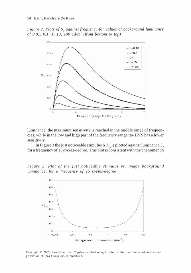
54 Barni, Bartolini & De Rosa
Copyright © 2005, Idea Group Inc. Copying or distributing in print or electronic forms without writtenpermission of Idea Group Inc. is prohibited.
luminance: the maximum sensitivity is reached in the middle range of frequen-cies, while in the low and high part of the frequency range the HVS has a lowersensitivity.
In Figure 3 the just noticeable stimulus ∆ Ljn is plotted against luminance L,
for a frequency of 15 cycles/degree. This plot is consistent with the phenomenon
Figure 3. Plot of the just noticeable stimulus vs. image backgroundluminance, for a frequency of 15 cycles/degree
Figure 2. Plots of Sc against frequency for values of background luminance
of 0.01, 0.1, 1, 10, 100 cd/m2 (from bottom to top)
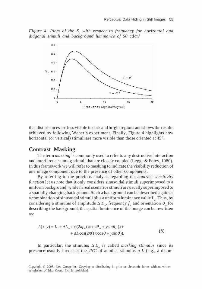
Perceptual Data Hiding in Still Images 55
Copyright © 2005, Idea Group Inc. Copying or distributing in print or electronic forms without writtenpermission of Idea Group Inc. is prohibited.
that disturbances are less visible in dark and bright regions and shows the resultsachieved by following Weber’s experiment. Finally, Figure 4 highlights howhorizontal (or vertical) stimuli are more visible than those oriented at 45°.
Contrast MaskingThe term masking is commonly used to refer to any destructive interaction
and interference among stimuli that are closely coupled (Legge & Foley, 1980).In this framework we will refer to masking to indicate the visibility reduction ofone image component due to the presence of other components.
By referring to the previous analysis regarding the contrast sensitivityfunction let us note that it only considers sinusoidal stimuli superimposed to auniform background, while in real scenarios stimuli are usually superimposed toa spatially changing background. Such a background can be described again asa combination of sinusoidal stimuli plus a uniform luminance value L
o. Thus, by
considering a stimulus of amplitude ∆ Lm, frequency f
m and orientation θ
m for
describing the background, the spatial luminance of the image can be rewrittenas:
)).cos(2cos(
))cos(2cos(),(
θθπθθπ
ysinxfL
ysinxfLLyxL mmmmo
+∆+++∆+=
(8)
In particular, the stimulus ∆ Lm is called masking stimulus since its
presence usually increases the JNC of another stimulus ∆ L (e.g., a distur-
Figure 4. Plots of the Sc with respect to frequency for horizontal and
diagonal stimuli and background luminance of 50 cd/m2

56 Barni, Bartolini & De Rosa
Copyright © 2005, Idea Group Inc. Copying or distributing in print or electronic forms without writtenpermission of Idea Group Inc. is prohibited.
bance). The stimuli can be coincident in frequency and orientation (i.e., fm = f and
θm = θ ), leading to iso-frequency masking, or non-coincident (i.e. f
m ≠ f and θ
m ≠
θ), leading to non- iso-frequency masking. In the first case, JNC elevation ismaximal; in the latter, JNC elevation decreases regularly as the maskingfrequency departs from the stimulus frequency.
In the following both iso and non-iso-frequency masking will be consid-ered and a masked just noticeable contrast function (JNC
m) detailed to model
these masking effects.
Iso-Frequency MaskingBy relying on the works by Watson (Watson, 1987, 1993),the masked JNC
can be written as a function of the non-masked JNC:
( ) ( )
( )( ) ,
,,,
,,,
,,,,,,
⋅
⋅=
o
om
oom
LwfJNC
LwfCF
LwfJNCLwfJNC
θθ
θθ
(9)
where F is a non-linear function indicating how much JNC increments inpresence of a masking signal, and C
m is the contrast of the masking image
component, that is, Cm = ∆L
m/L
o.
The function F(⋅) can be approximated by the following relation (Watson,1987):
( ) { },,1maxW
XXF = (10)
where W is an exponent lying between 0.4 and 0.95.Let us note that expression (10) does not take the so-called pedestal effect
into account (Legge & Foley, 1980). In fact, it assumes that the presence of onestimulus can only decrease the detectability of another stimulus at the samefrequency and orientation. Indeed, several studies have shown that a low valueof the masking contrast C
m increases noise visibility (Foley & Legge, 1981); in
particular, when the masking component is not perceptible, that is, Cm < JNC,
then a more exact expression for F would also assume values below one. InFigure 5, the trends of the masking function F(X) obtained by fitting experimentalresults (solid line) and by using equation 10 (dashed line) are shown: the pedestaleffect is also highlighted.
By inserting equation 10 in equation 9, we get:

Perceptual Data Hiding in Still Images 57
Copyright © 2005, Idea Group Inc. Copying or distributing in print or electronic forms without writtenpermission of Idea Group Inc. is prohibited.
( ) ( )( )( ) .
,,,
,,,,1max
,,,,,,
⋅
⋅=W
o
om
oom
LwfJNC
LwfC
LwfJNCLwfJNC
θθ
θθ
(11)
It is important to note that masking only affects the AC components of theimage. The effect of the DC coefficient on the threshold is expressed by equation6, in which the influence of background mean luminance L
o on human vision is
taken into account.
Non-Iso-Frequency MaskingWhen the masking frequency (f
m , θ
m ) departs from signal frequency (f, θ)
JNCm increment decreases. A possibility to model non-iso-frequency masking
consists in introducing in equation 11 a weighing function, which takes intoaccount that each frequency component contributes differently to the masking,according to its frequency position. The weighing function can be modelled asGaussian-like (Comes & Macq, 1990):
( ) ( ) ( ),
/logexp,/
2
2
2
22
−+−=−θσθθ
σθθ m
f
mmm
ffffg (12)
where
Figure 5. Plot of the masking function F(X) (solid line) and its approximation(dashed line) given by equation 10, where it is assumed W = 0.6 (Thepedestal effect is highlighted.)

58 Barni, Bartolini & De Rosa
Copyright © 2005, Idea Group Inc. Copying or distributing in print or electronic forms without writtenpermission of Idea Group Inc. is prohibited.
,2.1
,log2.1 2
θθσ
σ
B
B ff
=
=
(13)
.log327
,2
2 fB
B f
−=
=
θ
(14)
By inserting the weighing function (12) in the JNCm expression, the value of
the masked just noticeable contrast is obtained:
( ) ( )
( ) ( )( ) ,
,,,
,,,,/,1max
,,,,,,
−⋅
⋅=
W
mmm
mmmmmm
oom
LwfJNC
LwfCffg
LwfJNCLwfJNC
θθθθ
θθ
(15)
where the stimulus at spatial frequency (f , θ ) is masked by the stimulus at spatialfrequency (f
m , θ
m ). Note that the mean luminance’s L
o and L
m can be supposed
to be identical when both the frequencies f and fm belong to the same spatial
region. Furthermore, when (fm , θ
m ) = (f, θ) the weighing function assumes value
1, thus reducing to equation 11.
EXPLOITATION OF HVS CONCEPTSFOR DATA HIDING
It is widely known among watermarking researchers that HVS character-istics have to be carefully considered for developing a watermarking system thatminimises the image visual degradation while maximising robustness (Cox &Miller, 1997; Tewfik & Swanson, 1997). Let us, thus, see how the conceptsderiving from the analysis of the models of human perception can be exploitedfor better hiding data into images.
Basically, we distinguish two different approaches for considering HVSconcepts during the data embedding process. The former approach considers theselection of appropriate features that are most suitable to be modified, withoutdramatically affecting perceptual image quality. Basing on the characteristics
Perceptual Data Hiding in Still Images 59
Copyright © 2005, Idea Group Inc. Copying or distributing in print or electronic forms without writtenpermission of Idea Group Inc. is prohibited.
that control the HVS (i.e., the dependence of the contrast sensitivity onfrequency and luminance, and the masking effect), the idea is to locate whichimage features can better mask the embedded data. By following the secondapproach, the inserted data, embedded into an image without a particular care forthe selection of the most suitable features, are adapted to the local image contentfor better reducing their perceptibility. In other words, by referring to the justnoticeable contrast, the maximum amount of data that can be introduced into animage is locally adapted.
Let us consider host feature selection first. By carefully observing thesimple basic rules describing the mechanisms underlying the HVS we discussedabove, it is readily seen that some of them are more naturally expressed in thespatial domain, whereas others are more easily modelled in the frequencydomain. Let us consider, for example, the CSF and the masking models describedin the previous section. The most suitable domain to describe them is, obviously,the frequency domain. This is not the case, however, when the lower sensitivityto disturbances in bright and dark regions has to be taken into account, aphenomenon that is clearly easier to describe in the spatial domain. Despite theirsimplicity, these examples point out the difficulty of fully exploiting the charac-teristics of the HVS by simply choosing the set of features the mark has to beinserted in. Of course, this does not mean that a proper selection of the hostfeature is of no help in watermark hiding. On the contrary, many systems havebeen proposed where embedding is performed in a feature domain that is knownto be relatively more immune to disturbances. This is the case of frequencydomain watermarking algorithms. Let us consider the curves reported in Figures 2and 4. If we ignore very low frequencies (due to its very small extension theregion of very low frequencies is usually not considered), we see how watermarkhiding is more easily achieved avoiding marking the low frequency portion of thespectrum where disturbances are more easily perceived by the HSV. By relyingon perceptibility considerations only, the frequency portion of the spectrum turnsout to be a perfect place to hide information. When considering robustness toattacks, though, a high frequency watermark turns out to be too vulnerable toattacks such as low-pass filtering and JPEG compression, for which a low-passwatermark would be preferable. The most adopted solution consists in trading offbetween the two requirements, thus embedding the watermark into the medium-high portion of the frequency spectrum.
Similar considerations are valid for hybrid techniques, that is, those tech-niques embedding the watermark in a domain retaining both spatial and fre-quency localisation, as it is the case, for example, of wavelet- or block-DCT-based systems. In particular, the situation for block-DCT methods is identical tothe frequency domain case; high frequency coefficients are usually preferred forembedding, in order to reduce visibility. The same objective can be reached inthe DWT (Discrete Wavelet Transform) case by performing embedding in thefinest sub-bands. By starting from these considerations, we can conclude that
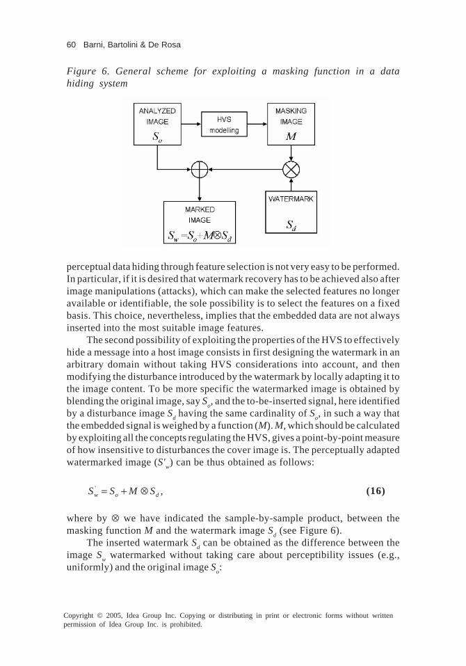
60 Barni, Bartolini & De Rosa
Copyright © 2005, Idea Group Inc. Copying or distributing in print or electronic forms without writtenpermission of Idea Group Inc. is prohibited.
perceptual data hiding through feature selection is not very easy to be performed.In particular, if it is desired that watermark recovery has to be achieved also afterimage manipulations (attacks), which can make the selected features no longeravailable or identifiable, the sole possibility is to select the features on a fixedbasis. This choice, nevertheless, implies that the embedded data are not alwaysinserted into the most suitable image features.
The second possibility of exploiting the properties of the HVS to effectivelyhide a message into a host image consists in first designing the watermark in anarbitrary domain without taking HVS considerations into account, and thenmodifying the disturbance introduced by the watermark by locally adapting it tothe image content. To be more specific the watermarked image is obtained byblending the original image, say S
o, and the to-be-inserted signal, here identified
by a disturbance image Sd having the same cardinality of S
o, in such a way that
the embedded signal is weighed by a function (M). M, which should be calculatedby exploiting all the concepts regulating the HVS, gives a point-by-point measureof how insensitive to disturbances the cover image is. The perceptually adaptedwatermarked image (S'
w) can be thus obtained as follows:
,'dow SMSS ⊗+= (16)
where by ⊗ we have indicated the sample-by-sample product, between themasking function M and the watermark image S
d (see Figure 6).
The inserted watermark Sd can be obtained as the difference between the
image Sw watermarked without taking care about perceptibility issues (e.g.,
uniformly) and the original image So:
Figure 6. General scheme for exploiting a masking function in a datahiding system

Perceptual Data Hiding in Still Images 61
Copyright © 2005, Idea Group Inc. Copying or distributing in print or electronic forms without writtenpermission of Idea Group Inc. is prohibited.
.owd SSS −= (17)
Regardless of the domain where watermark embedding has been per-formed, and on the embedding rule, this difference always models the signaladded to the original image for carrying the hidden information.
Whereas the general shape of M is easily found (e.g., lower values areexpected in flat areas, whereas textured areas should be characterised by highervalues of M), the exact definition of M is a complicated task, possibly involvinga complex manual tuning phase. Let us suppose, for example, that M takes valuesin the [0,1] interval; that is, the effect of the blending mask is only to reduce thewatermark strength in the most perceptually sensitive regions. In this case S
w
should be tuned so that the hidden signal is just below the visibility threshold invery textured regions (where M is likely to take values close to 1) and well visiblein all the other image areas. The mask, if properly designed, will reducewatermark strength on the other image regions in such a way to make itimperceptible everywhere. This procedure requires a manual tuning of thewatermark strength during the embedding process to achieve S
w and this limits
its efficacy when a large amount of images need to be watermarked.A different possibility is that mask values indicate directly the maximum
amount of the watermark strength that can be used for each region of the imageat hand: in this case mask values are not normalised between [0,1], and the imagecan be watermarked to achieve S
w without tuning the watermark strength in
advance.In the following sections we will describe how this second approach can be
implemented by relying on the HVS model introduced previously. Before goinginto the details of mask building, however, some limitations of classical HVSmodels will be pointed out and some innovative solutions outlined.
LIMITS OF CLASSICAL HVS MODELSAND A NEW APPROACH
Having described (in the second section) the main phenomena regulating theHVS, we now consider how these factors can be modelled to be used during adata hiding process. Let us recall the two concepts that mainly influence thehuman perception: the contrast sensitivity and the masking effect. The strictdependence of these factors on both frequency and luminance of the consideredstimuli imposes the need to achieve good models that simultaneously take intoaccount the two parameters.
Several HVS models have been proposed so far; without going into adescription of related literature, we will point out some important limits ofclassical approaches, and describe some possible solutions to cope with these
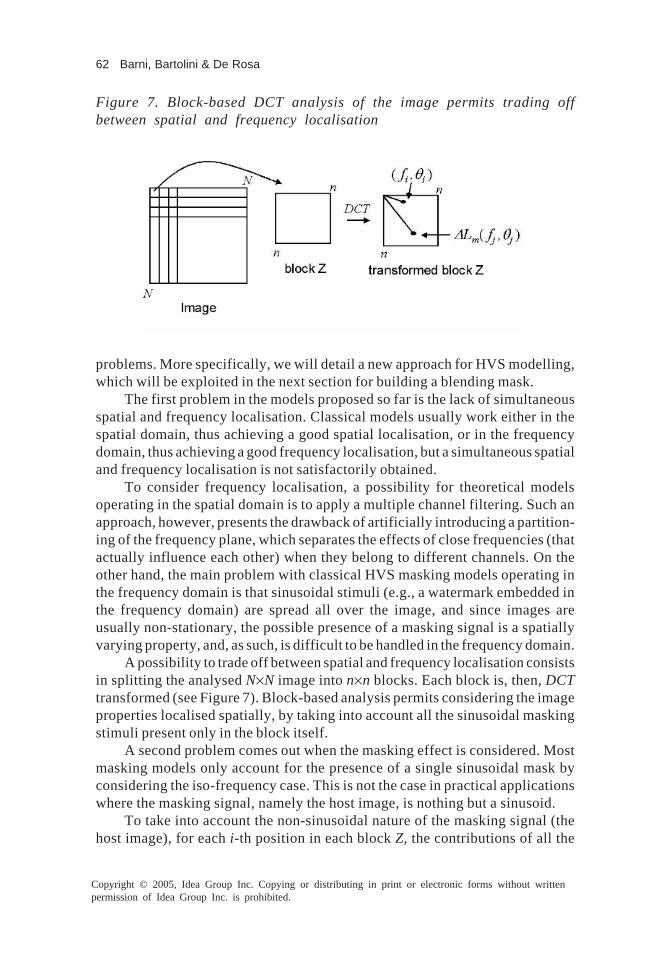
62 Barni, Bartolini & De Rosa
Copyright © 2005, Idea Group Inc. Copying or distributing in print or electronic forms without writtenpermission of Idea Group Inc. is prohibited.
problems. More specifically, we will detail a new approach for HVS modelling,which will be exploited in the next section for building a blending mask.
The first problem in the models proposed so far is the lack of simultaneousspatial and frequency localisation. Classical models usually work either in thespatial domain, thus achieving a good spatial localisation, or in the frequencydomain, thus achieving a good frequency localisation, but a simultaneous spatialand frequency localisation is not satisfactorily obtained.
To consider frequency localisation, a possibility for theoretical modelsoperating in the spatial domain is to apply a multiple channel filtering. Such anapproach, however, presents the drawback of artificially introducing a partition-ing of the frequency plane, which separates the effects of close frequencies (thatactually influence each other) when they belong to different channels. On theother hand, the main problem with classical HVS masking models operating inthe frequency domain is that sinusoidal stimuli (e.g., a watermark embedded inthe frequency domain) are spread all over the image, and since images areusually non-stationary, the possible presence of a masking signal is a spatiallyvarying property, and, as such, is difficult to be handled in the frequency domain.
A possibility to trade off between spatial and frequency localisation consistsin splitting the analysed N×N image into n×n blocks. Each block is, then, DCTtransformed (see Figure 7). Block-based analysis permits considering the imageproperties localised spatially, by taking into account all the sinusoidal maskingstimuli present only in the block itself.
A second problem comes out when the masking effect is considered. Mostmasking models only account for the presence of a single sinusoidal mask byconsidering the iso-frequency case. This is not the case in practical applicationswhere the masking signal, namely the host image, is nothing but a sinusoid.
To take into account the non-sinusoidal nature of the masking signal (thehost image), for each i-th position in each block Z, the contributions of all the
Figure 7. Block-based DCT analysis of the image permits trading offbetween spatial and frequency localisation

Perceptual Data Hiding in Still Images 63
Copyright © 2005, Idea Group Inc. Copying or distributing in print or electronic forms without writtenpermission of Idea Group Inc. is prohibited.
surrounding frequencies (fj , θ
j) of the same block must be considered. By
starting from the non- iso-frequency masking (equation 15), a sum of theweighed masking contributions on the whole block must be introduced.
Swanson et al. (1998) propose a summation rule of the form:
( ) ( )[
( ) ( )( ) .
,,,
,,,,/,1max
,,,,,,
2/12
−⋅
⋅= ∑∈
W
Zjj
Zjjmijij
ZjZiiZiim
LwfJNC
LwfCffg
LwfJNCLwfJNC
θθ
θθ
θθ
(18)
Such a rule presents some limits, which will be evidenced in a while, thuscalling for a different summation rule:
( ) ( )
( ) ( )( ) .
,,,
,,,,/,1max
,,,,,,
−⋅
⋅=
∑∈
W
Zj Zjj
Zjjmijij
ZiiZiim
LwfJNC
LwfCffg
LwfJNCLwfJNC
θθ
θθ
θθ
(19)
Let us note that the contrast of the masking component Cm is given by:
( ) ( ),
,,,,,
Z
jjmZjjm L
wfLLwfC
θθ
∆= (20)
where ∆Lm(f
j, θ
j ) is the amplitude of the sinusoidal masking component at
frequency (fj, θ
j ). Furthermore, for each block Z the mean luminance L
z is
measured based on the value of the corresponding DC coefficient.By comparing equations 18 and 19, it is evident that the novelty of equation
19 is the introduction of the ∑ operator inside the max operator. In particular, weconsider the sum of all the weighed masking contributions in the block and thenapply the formula proposed by Watson for the masked JNC to the sum, byconsidering it as a single contribution (this justifies the position of the exponentW outside the ∑ operator). The validity of the proposed expression can be verifiedby considering that if all masking frequency components are null, equation 19must reduce to the non-masked JNC (equation 11). Moreover, if only two closefrequencies contribute to masking and, as an extreme case, these two frequen-

64 Barni, Bartolini & De Rosa
Copyright © 2005, Idea Group Inc. Copying or distributing in print or electronic forms without writtenpermission of Idea Group Inc. is prohibited.
cies coincide, the masking effect of these two components must be added as asingle sinusoidal mask.
Such conditions are not satisfied by equation 18. It can be observed, in fact,that if no masking frequency is present in Z, the masked JNC differs from thenon-masked JNC by a factor (N
z)1/2, where N
z indicates the number of frequency
components contained in Z. In other words, contributions of masking componentsare always considered even when such components are null. From experimentalresults we evidenced that this situation occurs with a probability of around 50%.In addition, if equation 18 is adopted, when two coincident frequencies contributeto the masking, their masking effects cannot be added as a single sinusoidalmask.
As a third consideration it appears that all the techniques described so farproduce masking functions that depend only on the image characteristics, that is,on the characteristics of the masking signal, but not on the characteristics of thedisturbing signal. On the contrary, to estimate the maximum amount of disturbingsignal that can be inserted into an image by preserving its perceptual quality, itshould be considered how the modifications caused by watermark insertioninfluence each other. For example, we consider two contiguous coefficients ofa full-frame transform X
1(f
1) and X
2(f
2): the modifications imposed separately to
X1 and X
2 both contribute to the disturbance of both the corresponding frequen-
cies f1 and f
2. Instead, usual models do not consider this effect, by simply limiting
the amount of modification of each coefficient in dependence on the maskingcapability of its neighbourhood, but without considering the disturbance ofneighbouring coefficients.
A different approach must then be valued: instead of considering the singledisturbing components separately, we adopt a new formula for expressing thedisturb contrast for each position of the image, which we call the EquivalentDisturb Contrast C
deq. Such a formula takes into account all the considerations
expressed until now. In particular, to trade off between spatial and frequencylocalisation of noise, a block-based DCT decomposition is applied to thedisturbing image. Furthermore, to take into account the non-sinusoidal charac-teristics of the noise signal, for each i-th position of block Z all the disturbingcomponents belonging to the same block are added by using the weighingfunction g (equation 12). The equivalent disturb contrast C
deq is then written as:
( ) ( ) ( )∑∈
−=Zj
ZiidijijZiid LwfCffgLwfCeq
,,,,/,,, θθθθ (21)
where Cd is the contrast of the disturb component defined as:
( ) ( ),
,,,,,
Z
jjdZjjd L
wfLLwfC
θθ
∆= (22)
Perceptual Data Hiding in Still Images 65
Copyright © 2005, Idea Group Inc. Copying or distributing in print or electronic forms without writtenpermission of Idea Group Inc. is prohibited.
with ∆Ld (f
j, θ
j, w) being the amplitude of the sinusoidal noise signal at frequency
(fj, θ
j).In conclusion, in order to guarantee the invisibility of a disturbance (i.e., the
watermark) in a given image, for each frequency of each block Z, the equivalentdisturb contrast C
deq computed by equation 21 must be smaller than the value of
the masked just noticeable contrast JNCm obtained by equation 19, which is:
( ) ( ) ZZiLwfJNCLwfC ZiimZiideq∀∈∀≤ ,,,,,,, θθ (23)
IMPROVED MASK BUILDINGFOR DATA HIDING
The goal of this section is to present a method for building a mask thatindicates, for each region of a given image, the maximum allowable energy of thewatermark, under the constraint of image quality preservation. Such an approachwill be based on the enhanced HVS model presented in the previous section, andit will provide a masking function for improving watermark invisibility andstrength.
Before going on, it is worth noting that, so far, the behaviour of the HVS hasbeen described in terms of luminance; however, digital images are usually storedas grey-level values, and a watermarking system will directly affect grey-levelvalues. It is the goal of the next section to describe how grey-level values arerelated to the luminance perceived by the eye.
Luminance vs. Grey-Level Pixel ValuesThe luminance perceived by the eye does not depend solely on the grey level
of the pixels forming the image. On the contrary, several other factors must betaken into account, including: the environment lighting conditions, the shape ofthe filter modelling the low pass behaviour of the eye, and of course the way theimage is reproduced. In this framework we will concentrate on the case ofpictures reproduced by a cathode ray tube (CRT), for which the dependencebetween grey-level values and luminance is better known and more easilymodelled.
It is known that the relation between the grey level I of an image pixel andthe luminance L of the light emitted by the corresponding CRT element is a non-linear one. More specifically, such a relation as is usually modelled by theexpression (20):
( ) ,)( γmIqILL +== (24)

66 Barni, Bartolini & De Rosa
Copyright © 2005, Idea Group Inc. Copying or distributing in print or electronic forms without writtenpermission of Idea Group Inc. is prohibited.
with q defining luminance corresponding to a black image, m defines the contrastand γ accounts for the intrinsic non-linearity of the CRT emitting elements (thephosphors). While γ is a characteristic parameter of any given CRT, q and mdepend on “brightness” and “contrast” regulations usually accessible to the userthrough the CRT electronics.
A first possibility to map HVS concepts from luminance to grey-leveldomain consists in mapping grey-level values through (24), thus obtaining aluminance image, operating on this image according to the proposed model, andfinally going back to grey-level domain through the inverse of (24). Alternatively,we can try to directly write the just noticeable contrast as a function of grey-levelvalues. In analogy to equation 8, this can be done by considering a generic grey-level image composed of a uniform background I
o, a masking sinusoidal signal of
amplitude ∆Im and a disturbing sinusoidal stimulus of amplitude ∆I:
)),cos(2cos(
))cos(2cos(),(
θθπ
θθπ
ysinxfI
ysinxfIIyxI mmmmo
+∆+
++∆+=
(25)
which is mapped to a luminance pattern through equation 24:
( )
)),cos(2cos()('
))cos(2cos()('
)(),(),(
θθπ
θθπ
ysinxfIIL
ysinxfIIL
ILyxILyxL
o
mmmmo
o
+∆
++∆
+≈=
(26)
where L'(Io) is the derivative of the luminance mapping function given in (24) and
where a linear approximation of L(x,y) is adopted. By comparing (26) with (8)we have that, as a first approximation, ∆L
m = L'(I
o) ∆ I
m and ∆L = L'(I
o) ∆ I.
The just noticeable contrast in the grey-level domain can thus be expressed bythe formula:
( ) ( ) ( )
( )
( ).)(,,,)('
)(
)('
,,,
)('
,,,,,,,
oiioo
o
oo
ooii
oo
iijn
o
iijnoiiI
ILwfJNCILI
IL
ILI
LLwfJNC
ILI
wfL
I
wfIIwfJNC
θ
θ
θθθ
≈
≈=
=∆
≈∆
=
(27)
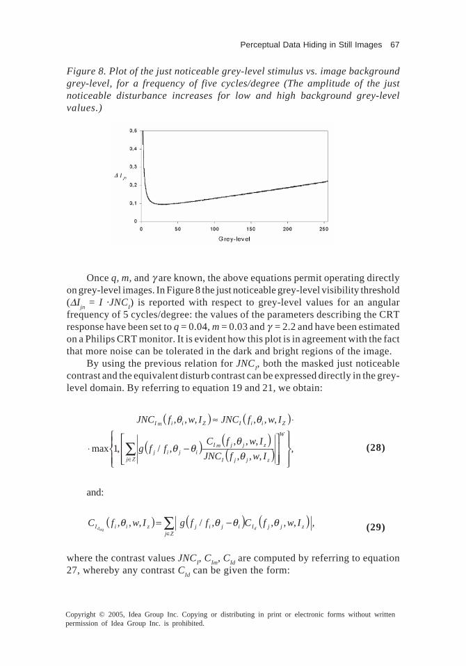
Perceptual Data Hiding in Still Images 67
Copyright © 2005, Idea Group Inc. Copying or distributing in print or electronic forms without writtenpermission of Idea Group Inc. is prohibited.
Once q, m, and γ are known, the above equations permit operating directlyon grey-level images. In Figure 8 the just noticeable grey-level visibility threshold(∆I
jn = I ·JNC
I) is reported with respect to grey-level values for an angular
frequency of 5 cycles/degree: the values of the parameters describing the CRTresponse have been set to q = 0.04, m = 0.03 and γ = 2.2 and have been estimatedon a Philips CRT monitor. It is evident how this plot is in agreement with the factthat more noise can be tolerated in the dark and bright regions of the image.
By using the previous relation for JNCI, both the masked just noticeable
contrast and the equivalent disturb contrast can be expressed directly in the grey-level domain. By referring to equation 19 and 21, we obtain:
( ) ( )
( ) ( )( ) ,
,,,
,,,,/,1max
,,,,,,
−⋅
⋅≈
∑∈
W
Zj zjjI
zjjmIijij
ZiiIZiimI
IwfJNC
IwfCffg
IwfJNCIwfJNC
θθ
θθ
θθ
(28)
and:
( ) ( ) ( ) ,,,,,/,,, ∑∈
−=Zj
zjjIijijziiI IwfCffgIwfCdeqd
θθθθ (29)
where the contrast values JNCI, C
Im, C
Id are computed by referring to equation
27, whereby any contrast CId
can be given the form:
Figure 8. Plot of the just noticeable grey-level stimulus vs. image backgroundgrey-level, for a frequency of five cycles/degree (The amplitude of the justnoticeable disturbance increases for low and high background grey-levelvalues.)
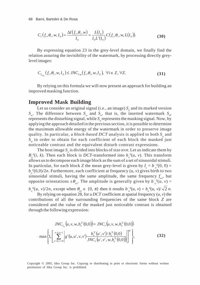
68 Barni, Bartolini & De Rosa
Copyright © 2005, Idea Group Inc. Copying or distributing in print or electronic forms without writtenpermission of Idea Group Inc. is prohibited.
( ) ( ) ( )( ) ( )( ).,,,
'
,,,,, 0
00
0
00 ILwfC
ILI
IL
I
wfIIwfC ii
iiiiI θθθ ≈∆= (30)
By expressing equation 23 in the grey-level domain, we finally find therelation assuring the invisibility of the watermark, by processing directly grey-level images:
( ) ( ) .,,,,,,,, ZZiIwfJNCIwfC ZiimIZiiIeqd
∀∈∀≤ θθ (31)
By relying on this formula we will now present an approach for building animproved masking function.
Improved Mask BuildingLet us consider an original signal (i.e., an image) S
o and its marked version
Sw. The difference between S
w and S
o, that is, the inserted watermark S
d,
represents the disturbing signal, while So represents the masking signal. Now, by
applying the approach detailed in the previous section, it is possible to determinethe maximum allowable energy of the watermark in order to preserve imagequality. In particular, a block-based DCT analysis is applied to both S
o and
Sd in order to obtain for each coefficient of each block the masked just
noticeable contrast and the equivalent disturb contrast expressions.The host image S
o is divided into blocks of size n×n. Let us indicate them by
Bo
Z(i, k). Then each block is DCT-transformed into bo
Z(u, v). This transformallows us to decompose each image block as the sum of a set of sinusoidal stimuli.In particular, for each block Z the mean grey-level is given by I
z = b’
oZ(0, 0) =
bo
Z(0,0)/2n. Furthermore, each coefficient at frequency (u, v) gives birth to twosinusoidal stimuli, having the same amplitude, the same frequency f
uv, but
opposite orientations ±θuv
. The amplitude is generally given by b’o
Z(u, v) =
bo
Z(u, v)/2n, except when θuv
∈ {0, π} then it results b’oZ(u, v) = b
oZ(u, v)/ 2 n.
By relying on equation 28, for a DCT coefficient at spatial frequency (u, v) thecontributions of all the surrounding frequencies of the same block Z areconsidered and the value of the masked just noticeable contrast is obtainedthrough the following expression:
( )( ) ( )( )
( ) ( ) ( )( )( ) ,
0,0,,','
0,0/','',,',',1max
0,0,,,0,0,,,
1,1
0',0''
''
''
⋅
⋅=
∑−−
==
Wnn
vuZ
oI
Zo
Zo
ZoI
ZoI
bwvuJNC
bvubvvuug
bwvuJNCbwvuJNCm
(32)
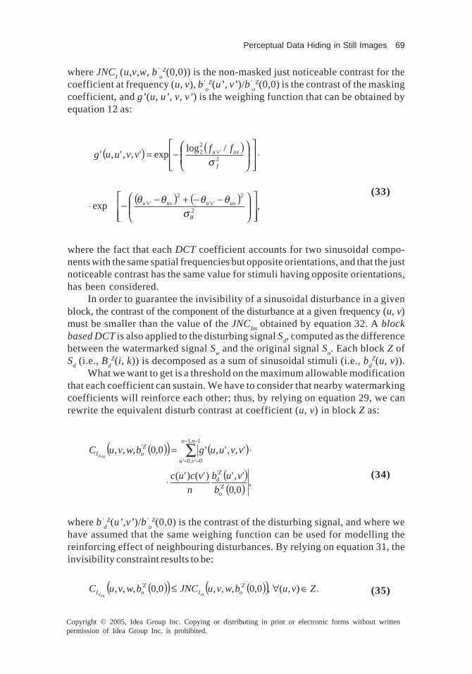
Perceptual Data Hiding in Still Images 69
Copyright © 2005, Idea Group Inc. Copying or distributing in print or electronic forms without writtenpermission of Idea Group Inc. is prohibited.
where JNCI (u,v,w, b’
oZ(0,0)) is the non-masked just noticeable contrast for the
coefficient at frequency (u, v), b’o
Z(u’, v’)/b’o
Z(0,0) is the contrast of the maskingcoefficient, and g’(u, u’, v, v’) is the weighing function that can be obtained byequation 12 as:
( ) ( )
( ) ( ),exp
/logexp',,','
2
2''
2''
2''
22
−−+−−⋅
⋅
−=
θσθθθθ
σ
uvvuuvvu
f
uvvu ffvvuug
(33)
where the fact that each DCT coefficient accounts for two sinusoidal compo-nents with the same spatial frequencies but opposite orientations, and that the justnoticeable contrast has the same value for stimuli having opposite orientations,has been considered.
In order to guarantee the invisibility of a sinusoidal disturbance in a givenblock, the contrast of the component of the disturbance at a given frequency (u, v)must be smaller than the value of the JNC
Im obtained by equation 32. A block
based DCT is also applied to the disturbing signal Sd, computed as the difference
between the watermarked signal Sw and the original signal S
o. Each block Z of
Sd (i.e., B
dZ(i, k)) is decomposed as a sum of sinusoidal stimuli (i.e., b
dZ(u, v)).
What we want to get is a threshold on the maximum allowable modificationthat each coefficient can sustain. We have to consider that nearby watermarkingcoefficients will reinforce each other; thus, by relying on equation 29, we canrewrite the equivalent disturb contrast at coefficient (u, v) in block Z as:
( )( ) ( )
( )( ) ,
0,0',')'()'(
',,','0,0,,,
'
'
1,1
0',0'
'
Zo
Zd
nn
vu
ZoI
b
vub
n
vcuc
vvuugbwvuCeqd
⋅
⋅= ∑−−
==
(34)
where b’d
Z(u’,v’)/b’o
Z(0,0) is the contrast of the disturbing signal, and where wehave assumed that the same weighing function can be used for modelling thereinforcing effect of neighbouring disturbances. By relying on equation 31, theinvisibility constraint results to be:
( )( ) ( )( ) .),(,0,0,,,0,0,,, '' ZvubwvuJNCbwvuC ZoI
ZoI meqd
∈∀≤ (35)

70 Barni, Bartolini & De Rosa
Copyright © 2005, Idea Group Inc. Copying or distributing in print or electronic forms without writtenpermission of Idea Group Inc. is prohibited.
Based on this approach, it is possible to build a masking function for spatiallyshaping any kind of watermark. By referring to equation 16, let us suppose thatthe mask M is block-wise constant, and let us indicate with M
Z the value assumed
by the mask in block Z. By exploiting the linearity property of the DCT transform,it is easy to verify that for satisfying the invisibility constraint we must have:
( )( ) ( )( ),),(
,0,0,,,0,0,,, ''
Zvu
bwvuJNCbwvuCM ZoI
ZoIZ meqd
∈∀
≤⋅(36)
thus boiling down to:
( )( )( )( ) .),(,
0,0,,,
0,0,,,min '
'
),(Zvu
bwvuC
bwvuJNCM
ZoI
ZoI
vuZ
eqd
m ∈∀= (37)
In Figures 9 to12 the resulting masking functions are shown for somestandard images, namely Lena, harbor, boat and airplane. These masksproduce reliable results, especially on textured areas. This is mainly due to thefact that the disturbing signal frequency content is also considered for buildingthe mask. Moreover, this method allows the maximum amount of watermarkingenergy that each image can tolerate to be automatically obtained, withoutresorting to manual tuning.
Figure 9. Mask obtained for the Lena image by means of the block-basedDCT perceptual model

Perceptual Data Hiding in Still Images 71
Copyright © 2005, Idea Group Inc. Copying or distributing in print or electronic forms without writtenpermission of Idea Group Inc. is prohibited.
Figure 10. Mask obtained for the Harbor image by means of the block-based DCT perceptual model
Figure 12. Mask obtained for the Airplane image by means of the block-based DCT perceptual model
Figure 11. Mask obtained for the Boat image by means of the block-basedDCT perceptual model
72 Barni, Bartolini & De Rosa
Copyright © 2005, Idea Group Inc. Copying or distributing in print or electronic forms without writtenpermission of Idea Group Inc. is prohibited.
CONCLUSIONSTwo of the main requirements a data-hiding scheme must satisfy regard
invisibility and robustness. The watermark must be invisible so that its presencedoes not affect the quality of the to-be-protected data; on the other hand, it mustbe resistant against the most common image manipulations, calling for thenecessity of embedding a watermark with as high a strength as possible. Theavailability of accurate models describing the phenomena regulating humanvision can give great advantage to satisfy the above requirements.
By starting from the analysis of the main important HVS concepts, we haveexplored how these factors can be exploited during the data-hiding process.Some important limits of the classical approaches have been pointed out, as wellas possible solutions to cope with them. Finally, we have detailed a new possibleapproach for HVS modelling and its exploitation for building a sensitivity mask.
Due to the space constraints, we limited our analysis to mask buildingalgorithms directly derived from the HVS model. For a couple of alternative(more heuristic) approaches to mask building, readers are referred to Bartoliniet al. (1998) and Pereira, Voloshynovskiy and Pun (2001). We also ignored visualmasking in domains other than the DFT and DCT ones. A detailed descriptionof an HVS-based data-hiding system operating in the wavelet domain, may befound in Barni, Bartolini and Piva (2001). To further explore the importance andthe role of perceptual considerations in a data hiding system, readers may alsorefer to Wolfgang et al. (1999) and Podilchuk and Zeng (1998).
We purposely limited our analysis to the case of grey-level images, since inmany cases the watermark is inserted in the luminance component of the hostimage. It has to be said, though, that advantages in terms of both robustness andimperceptibility are likely to be got by considering the way the HVS handlescolours.
REFERENCESAhumada, A.J., Jr., & Beard, B.L. (1996, February). Object detection in a noisy
scene. Proceedings of SPIE: Vol. 2657. Human Vision, Visual Process-ing, and Digital Display VII (pp. 190-199). Bellingham, WA.
Barni, M., Bartolini, F., & Piva, A. (2001, May). Improved wavelet-basedwatermarking through pixel-wise masking. IEEE Transactions on ImageProcessing, 10(5), 783-791.
Barten, P.G. (1990, October). Evaluation of subjective image quality with thesquare-root integral method. Journal of Optical Society of America,7(10), 2024-2031.
Bartolini, F., Barni, M., Cappellini, V., & Piva, A. (1998, October). Mask buildingfor perceptually hiding frequency embedded watermarks. Proceedings of

Perceptual Data Hiding in Still Images 73
Copyright © 2005, Idea Group Inc. Copying or distributing in print or electronic forms without writtenpermission of Idea Group Inc. is prohibited.
IEEE International Conference of Image Processing ’98, (vol. 1, pp.450-454). Chicago, IL.
Comes, S., & Macq, B. (1990, October). Human visual quality criterion.Proceedings of SPIE: Vol. 1360. Visual Communications and ImageProcessing (pp. 2-13). Lausanne, CH.
Cox, I., & Miller, M.L. (1997, February). A review of watermarking and theimportance of perceptual modeling. Proceedings of SPIE: Vol. 3016.Human Vision and Electronic Imaging II (pp. 92-99). Bellingham, WA.
Damera-Venkata, N., Kite, T.D., Geisler, W.S., Evans, B.L., & Bovik, A.C.(2000, April). Image quality assessment based on a degradation model.IEEE Transactions on Image Processing, 9(4), 636-650.
Delaigle, J.F., De Vleeschouwer, C., & Macq, B. (1998, May). Watermarkingalgorithm based on a human visual model. Signal Processing, 66(3), 319-336.
Eckert, M.P., & Bradley, A.P. (1998). Perceptual quality metrics applied to stillimage compression. Signal Processing, 70, 177-200.
Foley, J.M., & Legge, G.E. (1981). Contrast detection and near-thresholddiscrimination. Vision Research, 21, 1041-1053.
Kundur, D., & Hatzinakos, D. (1997, October). A robust digital watermarkingmethod using wavelet-based fusion. Proceedings of IEEE InternationalConference of Image Processing ’97: Vol. 1 (pp. 544-547). SantaBarbara, CA.
Legge, G.E., & Foley, J.M. (1980, December). Contrast masking in humanvision. Journal of Optical Society of America, 70(12), 1458-1471.
Pereira, S., Voloshynovskiy, S., & Pun, T. (2001, June). Optimal transformdomain watermark embedding via linear programming. Signal Process-ing, 81(6), 1251-1260.
Petitcolas, F.A., Anderson, R.J., & Kuhn, M.G. (1999, July). Information hiding:A survey. Proceedings of IEEE, 87(7), 1062-1078.
Podilchuk, C.I., & Zeng, W. (1998, May). Image-adaptive watermarking usingvisual models. IEEE Journal on Selected Areas in Communications,16(4), 525-539.
Swanson, M.D., Zhu, B., & Tewfik, A.H. (1998, May). Multiresolution scene-based video watermarking using perceptual models. IEEE Journal onSelected Areas in Communications, 16(4), 540-550.
Tewfik, A.H., & Swanson, M. (1997, July). Data hiding for multimedia person-alization, interaction, and protection. IEEE Signal Processing Magazine,14(4), 41-44.
Van Schyndel, R.G., Tirkel, A.Z., & Osborne, C.F. (1994, November). A digitalwatermark. Proceedings of IEEE International Conference of ImageProcessing ’94: Vol. 2 (pp. 86-90). Austin, TX.

74 Barni, Bartolini & De Rosa
Copyright © 2005, Idea Group Inc. Copying or distributing in print or electronic forms without writtenpermission of Idea Group Inc. is prohibited.
Voloshynovskiy, S., Pereira, S., Iquise, V., & Pun, T. (2001, June). Attackmodelling: Towards a second generation watermarking benchmark. SignalProcessing, 81(6), 1177-1214.
Watson, A.B. (1987, December). Efficiency of an image code based on humanvision. Journal of Optical Society of America, 4(12), 2401-2417.
Watson, A.B. (1993, February). Dct quantization matrices visually optimized forindividual images. Proceedings of SPIE: Vol. 1913. Human Vision,Visual Processing and Digital Display IV (pp. 202-216). Bellingham, WA.
Wolfgang, R.B., Podilchuk, C.I., & Delp, E.J. (1999, July). Perceptual water-marks for digital images and video. Proceedings of IEEE, 87(7), 1108-1126.

Audio Watermarking: Properties, Techniques and Evaluation 75
Copyright © 2005, Idea Group Inc. Copying or distributing in print or electronic forms without writtenpermission of Idea Group Inc. is prohibited.
Chapter III
Audio Watermarking:Properties, Techniques
and EvaluationAndrés Garay Acevedo, Georgetown University, USA
ABSTRACTThe recent explosion of the Internet as a collaborative medium has openedthe door for people who want to share their work. Nonetheless, theadvantages of such an open medium can pose very serious problems forauthors who do not want their works to be distributed without their consent.As new methods for copyright protection are devised, expectations aroundthem are formed and sometimes improvable claims are made. This chaptercovers one such technology: audio watermarking. First, the field isintroduced, and its properties and applications are discussed. Then, themost common techniques for audio watermarking are reviewed, and theframework is set for the objective measurement of such techniques. The lastpart of the chapter proposes a novel test and a set of metrics for thoroughbenchmarking of audio watermarking schemes. The development of such abenchmark constitutes a first step towards the standardization of therequirements and properties that such systems should display.
INTRODUCTIONThe recent explosion of the Internet as a collaborative medium has opened
the door for people who want to share their work. Nonetheless, the advantagesof such an open medium can pose very serious problems for authors who do notwant their works to be distributed without their consent. The digital nature of the

76 Garay Acevedo
Copyright © 2005, Idea Group Inc. Copying or distributing in print or electronic forms without writtenpermission of Idea Group Inc. is prohibited.
information that traverses through modern networks calls for new and improvedmethods for copyright protection1.
In particular, the music industry is facing several challenges (as well asopportunities) as it tries to adapt its business to the new medium. Contentprotection is a key factor towards a comprehensive information commerceinfrastructure (Yeung, 1998), and the industry expects new technologies willhelp them protect against the misappropriation of musical content.
One such technology, digital watermarking, has recently brought a tide ofpublicity and controversy. It is an emerging discipline, derived from an olderscience: steganography, or the hiding of a secret message within a seeminglyinnocuous cover message. In fact, some authors treat watermarking andsteganography as equal concepts, differentiated only by their final purpose(Johnson, Duric, & Jajodia, 2001).
As techniques for digital watermarking are developed, claims about theirperformance are made public. However, different metrics are typically used tomeasure performance, making it difficult to compare both techniques and claims.Indeed, there are no standard metrics for measuring the performance ofwatermarks for digital audio. Robustness does not correspond to the samecriteria among developers (Kutter & Petitcolas, 1999). Such metrics are neededbefore we can expect to see a commercial application of audio watermarkingproducts with a provable performance.
The objective of this chapter is to propose a methodology, includingperformance metrics, for evaluating and comparing the performance of digitalaudio watermarking schemes. In order to do this, it is necessary first to providea clear definition of what constitutes a watermark and a watermarking systemin the context of digital audio. This is the topic of the second section, which willprove valuable later in the chapter, as it sets a framework for the developmentof the proposed test.
After a clear definition of a digital watermark has been presented, a set ofkey properties and applications of digital watermarks can be defined anddiscussed. This is done in the third section, along with a classification of audiowatermarking schemes according to the properties presented. The importanceof these properties will be reflected on the proposed tests, discussed later in thechapter. The survey of different applications of watermarking techniques givesa practical view of how the technology can be used in a commercial and legalenvironment. The specific application of the watermarking scheme will alsodetermine the actual test to be performed to the system.
The fourth section presents a survey of specific audio watermarkingtechniques developed. Five general approaches are described: amplitude modi-fication, dither watermarking, echo watermarking, phase distortion, and spreadspectrum watermarking. Specific implementations of watermarking algorithms(i.e., test subjects) will be evaluated in terms of these categories2.

Audio Watermarking: Properties, Techniques and Evaluation 77
Copyright © 2005, Idea Group Inc. Copying or distributing in print or electronic forms without writtenpermission of Idea Group Inc. is prohibited.
The next three sections describe how to evaluate audio watermarkingtechnologies based on three different parameters: fidelity, robustness, andimperceptibility. Each one of these parameters will be precisely defined anddiscussed in its respective section, as they directly reflect the interests of thethree main actors involved in the communication process3: sender, attacker, andreceiver, respectively.
Finally, the last section provides an account on how to combine the threeparameters described above into a single performance measure of quality. Itmust be stated, however, that this measure should be dependant upon the desiredapplication of the watermarking algorithm (Petitcolas, 2000).
The topics discussed in this chapter come not only from printed sources butalso from very productive discussions with some of the active researchers in thefield. These discussions have been conducted via e-mail, and constitute a richcomplement to the still low number of printed sources about this topic. Eventhough the annual number of papers published on watermarking has been nearlydoubling every year in the last years (Cox, Miller, & Bloom, 2002), it is still low.Thus it was necessary to augment the literature review with personal interviews.
WATERMARKING: A DEFINITIONDifferent definitions have been given for the term watermarking in the
context of digital content. However, a very general definition is given by Cox etal. (2002), which can be seen as application independent: “We define watermarkingas the practice of imperceptibly altering a Work to embed a message about thatWork”. In this definition, the word work refers to a specific song, video orpicture4.
A crucial point is inferred by this definition, namely that the informationhidden within the work, the watermark itself, contains information about thework where it is embedded. This characteristic sets a basic requirement for awatermarking system that makes it different from a general steganographic tool.Moreover, by distinguishing between embedded data that relate to the coverwork and hidden data that do not, we can derive some of the applications andrequirements of the specific method. This is exactly what will be done later.
Another difference that is made between watermarking and steganographyis that the former has the additional notion of robustness against attacks (Kutter& Hartung, 2000). This fact also has some implications that will be covered later on.
Finally, if we apply Cox’s definition of watermarking into the field of audiosignal processing, a more precise definition, this time for audio watermarking,can be stated. Digital audio watermarking is defined as the process of “embed-ding a user specified bitsream in digital audio such that the addition of thewatermark (bitstream) is perceptually insignificant” (Czerwinski, Fromm, &Hodes, 1999).

78 Garay Acevedo
Copyright © 2005, Idea Group Inc. Copying or distributing in print or electronic forms without writtenpermission of Idea Group Inc. is prohibited.
This definition should be complemented with the previous one, so that we donot forget the watermark information refers to the digital audio file.
Elements of an Audio Watermarking SystemEmbedded watermarks are recovered by running the inverse process that
was used to embed them in the cover work, that is, the original work. This meansthat all watermarking systems consist of at least two generic building blocks: awatermark embedding system and a watermark recovery system.
Figure 1 shows a basic watermarking scheme, in which a watermark is bothembedded and recovered in an audio file. As can be seen, this process might alsoinvolve the use of a secret key. In general terms, given the audio file A, thewatermark W and the key K, the embedding process is a mapping of the formA×K×W→A'
Conversely, the recovery or extraction process receives a tentativelywatermarked audio file A', and a recovery key K' (which might be equal to K),and it outputs either the watermark W or a confidence measure about theexistence of W (Petitcolas, Anderson, & G., 1999).
At this point it is useful to attempt a formal definition of a watermarkingsystem, based on that of Katzenbeisser (2000), and which takes into account thearchitecture of the system. The quintuple ξ = ‹ C, W, K, D
k, E
k ›, where C is the
set of possible audio covers5, W the set of watermarks with |C| ≥ |W|, K the setof secret keys, E
k: C×K×W→C the embedding function and D
k: C×K→W the
extraction function, with the property that Dk (E
k (c, k, w) k) = w for all w ∈ W,
c ∈ C and k ∈ K is called a secure audio watermarking system.This definition is almost complete, but it fails to cover some special cases.
Some differences might arise between a real world system, and the one justdefined; for example, some detectors may not output the watermark W directlybut rather report the existence of it. Nonetheless, it constitutes a good approxi-mation towards a widely accepted definition of an audio watermarking system.
If one takes into account the small changes that a marking scheme can have,a detailed classification of watermarking schemes is possible. In this classifica-tion, the different schemes fall into three categories, depending on the set of
Figure 1. Basic watermarking system

Audio Watermarking: Properties, Techniques and Evaluation 79
Copyright © 2005, Idea Group Inc. Copying or distributing in print or electronic forms without writtenpermission of Idea Group Inc. is prohibited.
inputs and outputs (Kutter & Hartung, 2000). Furthermore, a specific and formaldefinition for each scheme can be easily given by adapting the definition justgiven for an audio watermarking system.
Private watermarking systems require the original audio A file in order toattempt recovery of the watermark W. They may also require a copy of theembedded watermark and just yield a yes or no answer to the question: does A'contain W?
Semi-private watermarking schemes do not use the original audio file fordetection, but they also answer the yes/no question shown above. This could bedescribed by the relation A'×K×W→{“Yes”, “No”}.
Public watermarking (also known as blind or oblivious watermarking)requires neither the original file A, nor the embedded watermark W. Thesesystems just extract n bits of information from the watermarked audio file. Ascan be seen, if a key is used then this corresponds to the definition given for asecure watermarking system.
Watermark as a Communication ProcessA watermarking process can be modeled as a communication process. In
fact, this assumption is used throughout this chapter. This will prove to bebeneficial in the next chapter when we differentiate between the requirementsof the content owner and consumer. A more detailed description of this modelcan be found in Cox et al. (2002).
In this framework, the watermarking process is viewed as a transmissionchannel through which the watermark message is communicated. Here thecover work is just part of the channel. This is depicted in Figure 2, based on thatfrom Cox et al. (2002).
In general terms, the embedding process consists of two steps. First, thewatermark message m is mapped into an added pattern6 W
a, of the same type and
dimension as the cover work A. When watermarking audio, the watermarkencoder produces an audio signal. This mapping may be done with a watermarkkey K. Next, W
a is embedded into the cover work in order to produce the
watermarked audio file A'.
Figure 2. Watermark communication process

80 Garay Acevedo
Copyright © 2005, Idea Group Inc. Copying or distributing in print or electronic forms without writtenpermission of Idea Group Inc. is prohibited.
After the pattern is embedded, the audio file is processed in some way. Thisis modeled as the addition of noise to the signal, which yields a noisy work A'
n.
The types of processing performed on the work will be discussed later, as theyare of no importance at this moment. However, it is important to state thepresence of noise, as any transmission medium will certainly induce it.
The watermark detector performs a process that is dependant on the typeof watermarking scheme. If the decoder is a blind or public decoder, then theoriginal audio file A is not needed during the recovery process, and only the keyK is used in order to decode a watermark message m
n. This is the case depicted
in Figure 2, as it is the one of most interest to us.Another possibility is for the detector to be informed. In this case, the
original audio cover A must be extracted from A'n in order to yield W
n, prior to
running the decoding process. In addition, a confidence measure can be theoutput of the system, rather than the watermark message.
PROPERTIES, CLASSIFICATIONAND APPLICATIONS
After a proper definition of a watermarking scheme, it is possible now totake a look at the fundamental properties that comprise a watermark. It can bestated that an ideal watermarking scheme will present all of the characteristicshere detailed, and this ideal type will be useful for developing a quality test.
However, in practice there exists a fundamental trade-off that restrictswatermark designers. This fundamental trade-off exists between three keyvariables: robustness, payload and perceptibility (Cox, Miller, Linnartz, &Kalker, 1999; Czerwinski et al., 1999; Johnson et al., 2001; Kutter & Petitcolas,1999; Zhao, Koch, & Luo, 1998). The relative importance given to each of thesevariables in a watermarking implementation depends on the desired applicationof the system.
Fundamental PropertiesA review of the literature quickly points out the properties that an ideal
watermarking scheme should possess (Arnold, 2000; Boney, Tewfik & Hamdy,1996; Cox, Miller, & Bloom, 2000; Cox et al., 1999, 2002; Kutter & Hartung,2000; Kutter & Petitcolas, 1999; Swanson, Zhu, Tewfik, & Boney, 1998). Theseare now discussed.
Imperceptibility. “The watermark should not be noticeable … nor should[it] degrade the quality of the content” (Cox et al., 1999). In general, the termrefers to a similarity between the original and watermarked versions of the coverwork.
Audio Watermarking: Properties, Techniques and Evaluation 81
Copyright © 2005, Idea Group Inc. Copying or distributing in print or electronic forms without writtenpermission of Idea Group Inc. is prohibited.
In the case of audio, the term audibility would be more appropriate;however, this could create some confusion, as the majority of the literature usesperceptibility. This is the same reason why the term fidelity is not used at thispoint, even though Cox et al. (1999) point out that if a watermark is trulyimperceptible, then it can be removed by perceptually-based lossy compressionalgorithms. In fact, this statement will prove to be a problem later when tryingto design a measure of watermark perceptibility. Cox’s statement implies thatsome sort of perceptibility criterion must be used not only to design thewatermark, but to quantify the distortion as well. Moreover, it implies that thisdistortion must be measured at the point where the audio file is being presentedto the consumer/receiver.
If the distortion is measured at the receiver’s end, it should also be measuredat the sender’s. That is, the distortion induced by a watermark must also bemeasured before any transmission process. We will refer to this characteristicat the sending end by using the term fidelity.
This distinction between the terms fidelity and imperceptibility is notcommon in the literature, but will be beneficial at a later stage. Differentiatingbetween the amount and characteristics of the noise or distortion that awatermark introduces in a signal before and after the transmission process takesinto account the different expectations that content owners and consumers havefrom the technology. However, this also implies that the metric used to evaluatethis effect must be different at these points. This is exactly what will be done lateron this chapter.
Artifacts introduced through a watermarking process are not only annoyingand undesirable, but may also reduce or destroy the commercial value of thewatermarked data (Kutter & Hartung, 2000). Nonetheless, the perceptibility ofthe watermark can increase when certain operations are performed on the coversignal.
Robustness refers to the ability to detect the watermark after commonsignal processing operations and hostile attacks. Examples of common opera-tions performed on audio files include noise reduction, volume adjustment ornormalization, digital to analog conversion, and so forth. On the other hand, ahostile attack is a process specifically designed to remove the watermark.
Not all watermarking applications require robustness against all possiblesignal processing operations. Only those operations likely to occur between theembedding of the mark and the decoding of it should be addressed. However, thenumber and complexity of attack techniques is increasing (Pereira,Voloshynovskiy, Madueño, Marchand-Maillet, & Pun, 2001; Voloshynovskiy,Pereira, Pun, Eggers, & Su, 2001), which means that more scenarios have to betaken into account when designing a system. A more detailed description of theseattacks is given in the sixth section.
82 Garay Acevedo
Copyright © 2005, Idea Group Inc. Copying or distributing in print or electronic forms without writtenpermission of Idea Group Inc. is prohibited.
Robustness deals with two different issues; namely the presence anddetection of the watermark after some processing operation. It is not necessaryto remove a watermark to render it useless; if the detector cannot report thepresence of the mark then the attack can be considered successful. This meansthat a watermarking scheme is robust when it is able to withstand a series ofattacks that try to degrade the quality of the embedded watermark, up to the pointwhere it’s removed, or its recovery process is unsuccessful. “No such perfectmethod has been proposed so far, and it is not clear yet whether an absolutelysecure watermarking method exists at all” (Kutter & Hartung, 2000).
Some authors prefer to talk about tamper resistance or even security whenreferring to hostile attacks; however, most of the literature encompasses thiscase under the term robustness.
The effectiveness of a watermarking system refers to the probability thatthe output of the embedder will be watermarked. In other words, it is theprobability that a watermark detector will recognize the watermark immediatelyafter inserting it in the cover work. What is most amazing about this definition isthe implication that a watermarking system might have an effectiveness of lessthan 100%. That is, it is possible for a system to generate marks that are not fullyrecoverable even if no processing is done to the cover signal. This happensbecause perfect effectiveness comes at a very high cost with respect to otherproperties, such as perceptibility (Cox et al., 2002). When a known watermarkis not successfully recovered by a detector it is said that a false negative, or type-II error, has occurred (Katzenbeisser, 2000).
Depending on the application, one might be willing to sacrifice someperformance in exchange for other characteristics. For example, if extremelyhigh fidelity is to be achieved, one might not be able to successfully watermarkcertain type of works without generating some kind of distortion. In some cases,the effectiveness can be determined analytically, but most of the time it has tobe estimated by embedding a large set of works with a given watermark and thentrying to extract that mark. However, the statistical characteristics of the test setmust be similar to those of the works that will be marked in the real world usingthe algorithm.
Data payload. In audio watermarking this term refers to the number ofembedded bits per second that are transmitted. A watermark that encodes N bitsis referred to as an N-bit watermark, and can be used to embed 2N differentmessages. It must be said that there is a difference between the encodedmessage m, and the actual bitstream that is embedded in the audio cover work.The latter is normally referred to as a pseudorandom (PN) sequence.
Many systems have been proposed where only one possible watermark canbe embedded. The detector then just determines whether the watermark ispresent or not. These systems are referred to as one-bit watermarks, as onlytwo different values can be encoded inside the watermark message. In discuss-

Audio Watermarking: Properties, Techniques and Evaluation 83
Copyright © 2005, Idea Group Inc. Copying or distributing in print or electronic forms without writtenpermission of Idea Group Inc. is prohibited.
ing the data payload of a watermarking method, it is also important to distinguishbetween the number of distinct watermarks that may be inserted, and the numberof watermarks that may be detected by a single iteration with a given watermarkdetector. In many watermarking applications, each detector need not test for allthe watermarks that might possibly be present (Cox et al., 1999). For example,one might insert two different watermarks into the same audio file, but only beinterested in recovering the last one to be embedded.
Other PropertiesSome of the properties reviewed in the literature are not crucial for testing
purposes; however they must be mentioned in order to make a thoroughdescription of watermarking systems.
• False positive rate. A false positive or type-I error is the detection of awatermark in a work that does not actually contain one. Thus a falsepositive rate is the expected number of false positives in a given number ofruns of the watermark detector. Equivalently, one can detect the probabilitythat a false positive will occur in a given detector run.In some applications a false positive can be catastrophic. For example,imagine a DVD player that incorrectly determines that a legal copy of a disk(for example a homemade movie) is a non-factory-recorded disk andrefuses to play it. If such an error is common, then the reputation of DVDplayers and consequently their market can be seriously damaged.
• Statistical invisibility. This is needed in order to prevent unauthorizeddetection and/or removal. Performing statistical tests on a set of watermarkedfiles should not reveal any information about the nature of the embeddedinformation, nor about the technique used for watermarking (Swanson etal., 1998). Johnson et al. (2001) provide a detailed description of knownsignatures that are created by popular information hiding tools. Theirtechniques can be also extended for use in some watermarking systems.
• Redundancy. To ensure robustness, the watermark information is embed-ded in multiple places on the audio file. This means that the watermarkcan usually be recovered from just a small portion of the watermarkedfile.
• Compression ratio, or similar compression characteristics as the originalfile. Audio files are usually compressed using different schemes, such asMPEG-Layer 3 audio compression. An audio file with an embeddedwatermark should yield a similar compression ratio as its unmarkedcounterpart, so that its value is not degraded. Moreover, the compressionprocess should not remove the watermark.
• Multiple watermarks. Multiple users should be able to embed a watermarkinto an audio file. This means that a user has to ideally be able to embed a

84 Garay Acevedo
Copyright © 2005, Idea Group Inc. Copying or distributing in print or electronic forms without writtenpermission of Idea Group Inc. is prohibited.
watermark without destroying any preexisting ones that might be alreadyresiding in the file. This must hold true even if the watermarking algorithmsare different.
• Secret keys. In general, watermarking systems should use one or morecryptographically secure keys to ensure that the watermark cannot bemanipulated or erased. This is important because once a watermark can beread by someone, this same person might alter it since both the location andembedding algorithm of the mark will be known (Kutter & Hartung, 2000).It is not safe to assume that the embedding algorithm is unknown to theattacker.As the security of the watermarking system relies in part on the use ofsecret keys, the keyspace must be large, so that a brute force attack isimpractical. In most watermarking systems the key is the PN-pattern itself,or at least is used as a seed in order to create it. Moreover, the watermarkmessage is usually encrypted first using a cipher key, before it is embeddedusing the watermark key. This practice adds security at two differentlevels. In the highest level of secrecy, the user cannot read or decode thewatermark, or even detect its presence. The second level of secrecypermits any user to detect the presence of the watermark, but the datacannot be decoded without the proper key.Watermarking systems in which the key is known to various detectors arereferred to as unrestricted-key watermarks. Thus, algorithms for use asunrestricted-key systems must employ the same key for every piece of data(Cox et al., 1999). Those systems that use a different key for eachwatermark (and thus the key is shared by only a few detectors) are knownas restricted-key watermarks.
• Computational cost. The time that it takes for a watermark to beembedded and detected can be a crucial factor in a watermarking system.Some applications, such as broadcast monitoring, require real time water-mark processing and thus delays are not acceptable under any circum-stances. On the other hand, for court disputes (which are rare), a detectionalgorithm that takes hours is perfectly acceptable as long as the effective-ness is high.
Additionally, the number of embedders and detectors varies according tothe application. This fact will have an effect on the cost of the watermarkingsystem. Applications such as DVD copy control need few embedders but adetector on each DVD player; thus the cost of recovering should be very low,while that of embedding could be a little higher7. Whether the algorithms areimplemented as plug-ins or dedicated hardware will also affect the economics ofdeploying a system.
Audio Watermarking: Properties, Techniques and Evaluation 85
Copyright © 2005, Idea Group Inc. Copying or distributing in print or electronic forms without writtenpermission of Idea Group Inc. is prohibited.
Different Types of WatermarksEven though this chapter does not relate to all kinds of watermarks that will
be defined, it is important to state their existence in order to later derive some ofthe possible applications of watermarking systems.
• Robust watermarks are simply watermarks that are robust against at-tacks. Even if the existence of the watermark is known, it should be difficultfor an attacker to destroy the embedded information without the knowledgeof the key8. An implication of this fact is that the amount of data that canbe embedded (also known as the payload) is usually smaller than in thecase of steganographic methods. It is important to say that watermarkingand steganographic methods are more complementary than competitive.
• Fragile watermarks are marks that have only very limited robustness(Kutter & Hartung, 2000). They are used to detect modifications of thecover data, rather than convey inerasable information, and usually becomeinvalid after the slightest modification of a work. Fragility can be anadvantage for authentication purposes. If a very fragile mark is detectedintact in a work, we can infer that the work has probably not been alteredsince the watermark was embedded (Cox et al., 2002). Furthermore, evensemi-fragile watermarks can help localize the exact location where thetampering of the cover work occurred.
• Perceptible watermarks, as the name states, are those that are easilyperceived by the user. Although they are usually applied to images (asvisual patterns or logos), it is not uncommon to have an audible signaloverlaid on top of a musical work, in order to discourage illegal copying. Asan example, the IBM Digital Libraries project (Memon & Wong, 1998;Mintzer, Magerlein, & Braudaway, 1996) has developed a visible water-mark that modifies the brightness of an image based on the watermark dataand a secret key. Even though perceptible watermarks are important forsome special applications, the rest of this chapter focuses on imperceptiblewatermarks, as they are the most common.
• Bitstream watermarks are marks embedded directly into compressedaudio (or video) material. This can be advantageous in environments wherecompressed bitstreams are stored in order to save disk space, like Internetmusic providers.
• Fingerprinting and labeling denote special applications of watermarks.They relate to watermarking applications where information such as thecreator or recipient of the data is used to form the watermark. In the caseof fingerprinting, this information consists of a unique code that uniquelyidentifies the recipient, and that can help to locate the source of a leak inconfidential information. In the case of labeling, the information embedded

86 Garay Acevedo
Copyright © 2005, Idea Group Inc. Copying or distributing in print or electronic forms without writtenpermission of Idea Group Inc. is prohibited.
is a unique data identifier, of interest for purposes such as library retrieving.A more thorough discussion is presented in the next section.
Watermark ApplicationsIn this section the seven most common application for watermarking
systems are presented. What is more important, all of them relate to the field ofaudio watermarking. It must be kept in mind that each of these applications willrequire different priorities regarding the watermark’s properties that have justbeen reviewed.• Broadcast monitoring. Different individuals are interested in broadcast
verification. Advertisers want to be sure that the ads they pay for are beingtransmitted; musicians want to ensure that they receive royalty paymentsfor the air time spent on their works.While one can think about putting human observers to record what they seeor hear on a broadcast, this method becomes costly and error prone. Thusit is desirable to replace it with an automated version, and digital water-marks can provide a solution. By embedding a unique identifier for eachwork, one can monitor the broadcast signal searching for the embeddedmark and thus compute the air time. Other solutions can be designed, butwatermarking has the advantage of being compatible with the installedbroadcast equipment, since the mark is included within the signal and doesnot occupy extra resources such as other frequencies or header files.Nevertheless, it is harder to embed a mark than to put it on an extra header,and content quality degradation can be a concern.
• Copyright owner identification. Under U.S. law, the creator of anoriginal work holds copyright to it the instant the work is recorded in somephysical form (Cox et al., 2002). Even though it is not necessary to placea copyright notice in distributed copies of work, it is considered a goodpractice, since a court can award more damages to the owner in the caseof a dispute.However, textual copyright notices9 are easy to remove, even withoutintention. For example, an image may be cropped prior to publishing. In thecase of digital audio the problem is even worse, as the copyright notice isnot visible at all times.Watermarks are ideal for including copyright notices into works, as theycan be both imperceptible and inseparable from the cover that containsthem (Mintzer, Braudaway, & Bell, 1998). This is probably the reason whycopyright protection is the most prominent application of watermarkingtoday (Kutter & Hartung, 2000). The watermarks are used to resolverightful ownership, and thus require a very high level of robustness (Arnold,2000). Furthermore, additional issues must be considered; for example, themarks must be unambiguous, as other parties can try to embed counterfeit

Audio Watermarking: Properties, Techniques and Evaluation 87
Copyright © 2005, Idea Group Inc. Copying or distributing in print or electronic forms without writtenpermission of Idea Group Inc. is prohibited.
copyright notices. Nonetheless, it must be stated that the legal impact ofwatermark copyright notices has not yet been tested in court.
• Proof of ownership. Multimedia owners may want to use watermarks notjust to identify copyright ownership, but also to actually prove ownership.This is something that a textual notice cannot easily do, since it can beforged.One way to resolve an ownership dispute is by using a central repository,where the author registers the work prior to distribution. However, this canbe too costly10 for many content creators. Moreover, there might be lack ofevidence (such as sketch or film negatives) to be presented at court, or suchevidence can even be fabricated.Watermarks can provide a way for authenticating ownership of a work.However, to achieve the level of security required for proof of ownership,it is probably necessary to restrict the availability of the watermark detector(Cox et al., 2002). This is thus not a trivial task.
• Content authentication. In authentication applications the objective is todetect modifications of the data (Arnold, 2000). This can be achieved withfragile watermarks that have low robustness to certain modifications. Thisproves to be very useful, as it is becoming easier to tamper with digitalworks in ways that are difficult to detect by a human observer.The problem of authenticating messages has been well studied in cryptog-raphy; however, watermarks are a powerful alternative as the signature isembedded directly into the work. This eliminates the problem of makingsure the signature stays with the work. Nevertheless, the act of embeddingthe watermark must not change the work enough to make it appear invalidwhen compared with the signature. This can be accomplished by separatingthe cover work in two parts: one for which the signature is computed, andthe other where it is embedded.Another advantage of watermarks is that they are modified along with thework. This means that in certain cases the location and nature of theprocessing within the audio cover can be determined and thus inverted. Forexample, one could determine if a lossy compression algorithm has beenapplied to an audio file11.
• Transactional watermarks. This is an application where the objective isto convey information about the legal recipient of digital data, rather thanthe source of it. This is done mainly to identify single distributed copies ofdata, and thus monitor or trace back illegally produced copies of data thatmay circulate12.The idea is to embed a unique watermark in each distributed copy of a work,in the process we have defined as fingerprinting. In these systems, thewatermarks must be secure against a collusion attack, which is explainedin the sixth section, and sometimes have to be extracted easily, as in thecase of automatic Web crawlers that search for pirated copies of works.

88 Garay Acevedo
Copyright © 2005, Idea Group Inc. Copying or distributing in print or electronic forms without writtenpermission of Idea Group Inc. is prohibited.
• Copy control/device control. Transactional watermarks as well aswatermarks for monitoring, identification, and proof of ownership do notprevent illegal copying (Cox et al., 2000). Copy protection is difficult toachieve in open systems, but might be desirable in proprietary ones. In suchsystems it is possible to use watermarks to indicate if the data can be copiedor not (Mintzer et al., 1998).The first and strongest line of defense against illegal copying is encryption,as only those who possess the decryption key can access the content. Withwatermarking, one could do a very different process: allow the media to beperceived, yet still prevent it from being recorded. If this is the case, awatermark detector must be included on every manufactured recorder,preferably in a tamper resistant device. This constitutes a serious nontech-nical problem, as there is no natural incentive for recording equipmentmanufacturers to include such a detector on their machines. This is due tothe fact that the value of the recorder is reduced from the point of view ofthe consumer.Similarly, one could implement play control, so that illegal copies can bemade but not played back by compliant equipment. This can be done bychecking a media signature, or if the work is properly encrypted forexample. By mixing these two concepts, a buyer will be left facing twopossibilities: buying a compliant device that cannot play pirated content, ora noncompliant one that can play pirated works but not legal ones.In a similar way, one could control a playback device by using embeddedinformation in the media they reproduce. This is known as device control.For example, one could signal how a digital audio stream should beequalized, or even extra information about the artist. A more extreme casecan be to send information in order to update the firmware of the playbackdevice while it is playing content, or to order it to shut down at a certain time.This method is practical, as the need for a signaling channel can beeliminated.
• Covert communication. Even though it contradicts the definition ofwatermark given before, some people may use watermarking systems inorder to hide data and communicate secretly. This is actually the realm ofsteganography rather than watermarking, but many times the boundariesbetween these two disciplines have been blurred. Nonetheless, in thecontext of this chapter, the hidden message is not a watermark but rathera robust covert communication.The use of watermarks for hidden annotation (Zhao et al., 1998), or labeling,constitutes a different case, where watermarks are used to create hiddenlabels and annotations in content such as medical imagery or geographicmaps, and indexes in multimedia content for retrieval purposes. In thesecases, the watermark requirements are specific to the actual media where

Audio Watermarking: Properties, Techniques and Evaluation 89
Copyright © 2005, Idea Group Inc. Copying or distributing in print or electronic forms without writtenpermission of Idea Group Inc. is prohibited.
the watermark will be embedded. Using a watermark that distorts apatient’s radiography can have serious legal consequences, while therecovery speed is crucial in multimedia retrieval.
AUDIO WATERMARKING TECHNIQUESIn this section the five most popular techniques for digital audio watermarking
are reviewed. Specifically, the different techniques correspond to the methodsfor merging (or inserting) the cover data and the watermark pattern into a singlesignal, as was outlined in the communication model of the second section.
There are two critical parameters to most digital audio representations:sample quantization method and temporal sampling rate. Data hiding in audiosignals is especially challenging, because the human auditory system (HAS)operates over a wide dynamic range. Sensitivity to additive random noise isacute. However, there are some “holes” available. While the HAS has a largedynamic range, it has a fairly small differential range (Bender, Gruhl, Morimoto,& Lu, 1996). As a result, loud sounds tend to mask out quiet sounds. This effectis known as masking, and will be fully exploited in some of the techniquespresented here (Swanson et al., 1998).
These techniques do not correspond to the actual implementation ofcommercial products that are available, but rather constitute the basis for someof them. Moreover, most real world applications can be considered a particularcase of the general methods described below.
Finally, it must be stated that the methods explained are specific to thedomain of audio watermarking. Several other techniques that are very popularfor hiding marks in other types of media, such as discrete cosine transform(DCT) coefficient quantization in the case of digital images, are not discussed.This is done because the test described in the following sections is related onlyto watermarking of digital audio.
Amplitude ModificationThis method, also known as least significant bit (LSB) substitution, is both
common and easy to apply in both steganography and watermarking (Johnson &Katzenbeisser, 2000), as it takes advantage of the quantization error that usuallyderives from the task of digitizing the audio signal.
As the name states, the information is encoded into the least significant bitsof the audio data. There are two basic ways of doing this: the lower order bitsof the digital audio signal can be fully substituted with a pseudorandom (PN)sequence that contains the watermark message m, or the PN-sequence can beembedded into the lower order bitstream using the output of a function thatgenerates the sequence based on both the nth bit of the watermark message andthe nth sample of the audio file (Bassia & Pitas, 1998; Dugelay & Roche, 2000).

90 Garay Acevedo
Copyright © 2005, Idea Group Inc. Copying or distributing in print or electronic forms without writtenpermission of Idea Group Inc. is prohibited.
Ideally, the embedding capacity of an audio file with this method is 1 kbpsper 1 kHz of sampled data. That is, if a file is sampled at 44 kHz then it is possibleto embed 44 kilobits on each second of audio. In return for this large channelcapacity, audible noise is introduced. The impact of this noise is a direct functionof the content of the host signal. For example, crowd noise during a rock concertwould mask some of the noise that would be audible in a string quartetperformance. Adaptive data attenuation has been used to compensate for thisvariation in content (Bender et al., 1996). Another option is to shape the PN-sequence itself so that it matches the audio masking characteristics of the coversignal (Czerwinski et al., 1999).
The major disadvantage of this method is its poor immunity to manipulation.Encoded information can be destroyed by channel noise, resampling, and soforth, unless it is encoded using redundancy techniques. In order to be robust,these techniques reduce the data rate, often by one to two orders of magnitude.Furthermore, in order to make the watermark more robust against localizedfiltering, a pseudorandom number generator can be used to spread the messageover the cover in a random manner. Thus, the distance between two embeddedbits is determined by a secret key (Johnson & Katzenbeisser, 2000). Finally, insome implementations the PN-sequence is used to retrieve the watermark fromthe audio file. In this way, the watermark acts at the same time as the key to thesystem.
Recently proposed systems use amplitude modification techniques in atransform space rather than in the time (or spatial) domain. That is, a transfor-mation is applied to the signal, and then the least significant bits of the coefficientsrepresenting the audio signal A on the transform domain are modified in order toembed the watermark W. After the embedding, the inverse transformation isperformed in order to obtain the watermarked audio file A’. In this case, thetechnique is also known as coefficient quantization. Some of the transforma-tions used for watermarking are the discrete Fourier transform (DFT), discretecosine transform (DCT), Mellin-Fourier transform, and wavelet transform(Dugelay & Roche, 2000). However, their use is more popular in the field ofimage and video watermarking.
Dither WatermarkingDither is a noise signal that is added to the input audio signal to provide
better sampling of that input when digitizing the signal (Czerwinski et al., 1999).As a result, distortion is practically eliminated, at the cost of an increased noisefloor.
To implement dithering, a noise signal is added to the input audio signal witha known probability distribution, such as Gaussian or triangular. In the particularcase of dithering for watermark embedding, the watermark is used to modulatethe dither signal. The host signal (or original audio file) is quantized using an
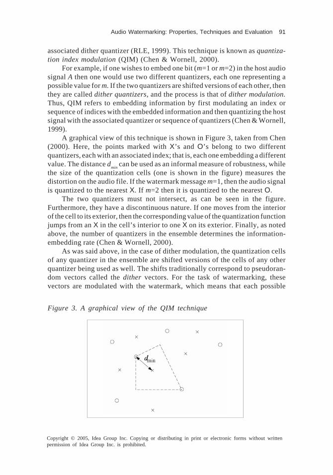
Audio Watermarking: Properties, Techniques and Evaluation 91
Copyright © 2005, Idea Group Inc. Copying or distributing in print or electronic forms without writtenpermission of Idea Group Inc. is prohibited.
associated dither quantizer (RLE, 1999). This technique is known as quantiza-tion index modulation (QIM) (Chen & Wornell, 2000).
For example, if one wishes to embed one bit (m=1 or m=2) in the host audiosignal A then one would use two different quantizers, each one representing apossible value for m. If the two quantizers are shifted versions of each other, thenthey are called dither quantizers, and the process is that of dither modulation.Thus, QIM refers to embedding information by first modulating an index orsequence of indices with the embedded information and then quantizing the hostsignal with the associated quantizer or sequence of quantizers (Chen & Wornell,1999).
A graphical view of this technique is shown in Figure 3, taken from Chen(2000). Here, the points marked with X’s and O’s belong to two differentquantizers, each with an associated index; that is, each one embedding a differentvalue. The distance d
min can be used as an informal measure of robustness, while
the size of the quantization cells (one is shown in the figure) measures thedistortion on the audio file. If the watermark message m=1, then the audio signalis quantized to the nearest X. If m=2 then it is quantized to the nearest O.
The two quantizers must not intersect, as can be seen in the figure.Furthermore, they have a discontinuous nature. If one moves from the interiorof the cell to its exterior, then the corresponding value of the quantization functionjumps from an X in the cell’s interior to one X on its exterior. Finally, as notedabove, the number of quantizers in the ensemble determines the information-embedding rate (Chen & Wornell, 2000).
As was said above, in the case of dither modulation, the quantization cellsof any quantizer in the ensemble are shifted versions of the cells of any otherquantizer being used as well. The shifts traditionally correspond to pseudoran-dom vectors called the dither vectors. For the task of watermarking, thesevectors are modulated with the watermark, which means that each possible
Figure 3. A graphical view of the QIM technique

92 Garay Acevedo
Copyright © 2005, Idea Group Inc. Copying or distributing in print or electronic forms without writtenpermission of Idea Group Inc. is prohibited.
embedded signal maps uniquely to a different dither vector. The host signal A isthen quantized with the resulting dithered quantizer in order to crate thewatermarked audio signal A'.
Echo WatermarkingEcho watermarking attempts to embed information on the original discrete
audio signal A(t) by introducing a repeated version of a component of the audiosignal with small enough offset (or delay), initial amplitude and decay rateαA(t – ∆t) to make it imperceptible. The resulting signal can be then expressedas A'(t) = A(t) + αA(t – ∆t).
In the most basic echo watermarking scheme, the information is encoded inthe signal by modifying the delay between the signal and the echo. This meansthat two different values ∆t and ∆t' are used in order to encode either a zero ora one. Both offset values have to be carefully chosen in a way that makes thewatermark both inaudible and recoverable (Johnson & Katzenbeisser, 2000).
As the offset between the original and the echo decreases, the two signalsblend. At a certain point, the human ear cannot distinguish between the twosignals. The echo is perceived as added resonance (Bender et al., 1996). Thispoint is hard to determine exactly, as it depends on many factors such as thequality of the original recording, the type of sound being echoed, and the listener.However, in general one can expect the value of the offset ∆t to be around onemillisecond.
Since this scheme can only embed one bit in a signal, a practical approachconsists of dividing the audio file into various blocks prior to the encodingprocess. Then each block is used to encode a bit, with the method describedabove. Moreover, if consecutive blocks are separated by a random number ofunused samples, the detection and removal of the watermark becomes moredifficult (Johnson & Katzenbeisser, 2000). Finally, all the blocks are concat-enated back, and the watermarked audio file A' is created. This technique resultsin an embedding rate of around 16 bits per second without any degradation of thesignal. Moreover, in some cases the resonance can even create a richer sound.
For watermark recovery, a technique known as cepstrum autocorrelationis used (Czerwinski et al., 1999). This technique produces a signal with twopronounced amplitude humps or spikes. By measuring the distance betweenthese two spikes, one can determine if a one or a zero was initially encoded inthe signal. This recovery process has the benefit that the original audio file A isnot needed. However, this benefit also becomes a drawback in that the schemepresented here is susceptible to attack. This will be further explained in the sixth section.
Phase CodingIt is known that the human auditory system is less sensitive to the phase
components of sound than to the noise components, a property that is exploited

Audio Watermarking: Properties, Techniques and Evaluation 93
Copyright © 2005, Idea Group Inc. Copying or distributing in print or electronic forms without writtenpermission of Idea Group Inc. is prohibited.
by some audio compression schemes. Phase coding (or phase distortion) makesuse of this characteristic as well (Bender et al., 1996; Johnson & Katzenbeisser,2000).
The method works by substituting the phase of the original audio signal Awith one of two reference phases, each one encoding a bit of information. Thatis, the watermark data W is represented by a phase shift in the phase of A.
The original signal A is split into a series of short sequences Ai, each one of
length l. Then a discrete Fourier transform (DFT) is applied to each one of theresulting segments. This transforms the signal representation from the timedomain to the frequency domain, thus generating a matrix of phases Φ and amatrix of Fourier transform magnitudes.
The phase shifts between consecutive signal segments must be preservedin the watermarked file A'. This is necessary because the human auditory systemis very sensitive to relative phase differences, but not to absolute phase changes.In other words, the phase coding method works by substituting the phase of theinitial audio segment with a reference phase that represents the data. After this,the phase of subsequent segments is adjusted in order to preserve the relativephases between them (Bender et al., 1996).
Given this, the embedding process inserts the watermark information in the
phase vector of the first segment of A, namely 0Φ�
. Then it creates a new phase
matrix Φ', using the original phase differences found in Φ.After this step, the original matrix of Fourier transform magnitudes is used
alongside the new phase matrix Φ' to construct the watermarked audio signalA', by applying the inverse Fourier transform (that is, converting the signal backto the time domain). At this point, the absolute phases of the signal have beenmodified, but their relative differences are preserved. Throughout the process,the matrix of Fourier amplitudes remains constant. Any modifications to it couldgenerate intolerable degradation (Dugelay & Roche, 2000).
In order to recover the watermark, the length of the segments, the DFTpoints, and the data interval must be known at the receiver. When the signal isdivided into the same segments that were used for the embedding process, thefollowing step is to calculate the DFT for each one of these segments. Once thetransformation has been applied, the recovery process can measure the value of
vector 0Φ�
and thereby restore the originally encoded value for W.
With phase coding, an embedding rate between eight and 32 bits per secondis possible, depending on the audio context. The higher rates are usually achievedwhen there is a noisy background in the audio signal. A higher embedding ratecan result in phase dispersion, a distortion13 caused by a break in the relationshipof the phases between each of the frequency components (Bender et al.,1996).

94 Garay Acevedo
Copyright © 2005, Idea Group Inc. Copying or distributing in print or electronic forms without writtenpermission of Idea Group Inc. is prohibited.
Spread Spectrum WatermarkingSpread spectrum techniques for watermarking borrow most of the theory
from the communications community (Czerwinski et al., 1999). The main idea isto embed a narrow-band signal (the watermark) into a wide-band channel (theaudio file). The characteristics of both A and W seems to suit this model perfectly.In addition, spread spectrum techniques offer the possibility of protecting thewatermark privacy by using a secret key to control the pseudorandom sequencegenerator that is needed in the process.
Generally, the message used as the watermark is a narrow band signalcompared to the wide band of the cover (Dugelay & Roche, 2000; Kirovski &Malvar, 2001). Spread spectrum techniques allow the frequency bands to bematched before embedding the message. Furthermore, high frequencies arerelevant for the invisibility of the watermark but are inefficient as far asrobustness is concerned, whereas low frequencies have the opposite character-istics. If a low energy signal is embedded on each of the frequency bands, thisconflict is partially solved. This is why spread spectrum techniques are valuablenot only for robust communication but for watermarking as well.
There are two basic approaches to spread spectrum techniques: directsequence and frequency hopping. In both of these approaches the idea is tospread the watermark data across a large frequency band, namely the entireaudible spectrum.
In the case of direct sequence, the cover signal A is modulated by thewatermark message m and a pseudorandom (PN) noise sequence, which has awide frequency spectrum. As a consequence, the spectrum of the resultingmessage m' is spread over the available band. Then, the spread message m' isattenuated in order to obtain the watermark W. This watermark is then added tothe original file, for example as additive random noise, in order to obtain thewatermarked version A'. To keep the noise level down, the attenuation per-formed to m' should yield a signal with about 0.5% of the dynamic range of thecover file A (Bender et al., 1996).
In order to recover the watermark, the watermarked audio signal A' ismodulated with the PN-sequence to remove it. The demodulated signal is then W.However, some keying mechanisms can be used when embedding the water-mark, which means that at the recovery end a detector must also be used. Forexample, if bi-phase shift keying is used when embedding W, then a phase detectormust be used at the recovery process (Czerwinski et al., 1999).
In the case of frequency hopping, the cover frequency is altered using arandom process, thus describing a wide range of frequency values. That is, thefrequency-hopping method selects a pseudorandom subset of the data to bewatermarked. The watermark W is then attenuated and merged with the selecteddata using one of the methods explained in this chapter, such as coefficient

Audio Watermarking: Properties, Techniques and Evaluation 95
Copyright © 2005, Idea Group Inc. Copying or distributing in print or electronic forms without writtenpermission of Idea Group Inc. is prohibited.
quantization in a transform domain. As a result, the modulated watermark has awide spectrum.
For the detection process, the pseudorandom generator used to alter thecover frequency is used to recover the parts of the signal where the watermarkis hidden. Then the watermark can be recovered by using the detection methodthat corresponds to the embedding mechanism used.
A crucial factor for the performance of spread spectrum techniques is thesynchronization between the watermarked audio signal A' and the PN-sequence(Dugelay & Roche, 2000; Kirovski & Malvar, 2001). This is why the particularPN-sequence used acts as a key to the recovery process. Nonetheless, someattacks can focus on this delicate aspect of the model.
MEASURING FIDELITYArtists, and digital content owners in general, have many reasons for
embedding watermarks in their copyrighted works. These reasons have beenstated in the previous sections. However, there is a big risk in performing suchan operation, as the quality of the musical content might be degraded to a pointwhere its value is diminished. Fortunately, the opposite is also possible and, ifdone right, digital watermarks can add value to content (Acken, 1998).
Content owners are generally concerned with the degradation of the coversignal quality, even more than users of the content (Craver, Yeo, & Yeung,1998). They have access to the unwatermarked content with which to comparetheir audio files. Moreover, they have to decide between the amount of tolerancein quality degradation from the watermarking process and the level of protectionthat is achieved by embedding a stronger signal. As a restriction, an embeddedwatermark has to be detectable in order to be valuable.
Given this situation, it becomes necessary to measure the impact that amarking scheme has on an audio signal. This is done by measuring the fidelity ofthe watermarked audio signal A', and constitutes the first measure that is definedin this chapter.
As fidelity refers to the similitude between an original and a watermarkedsignal, a statistical metric must be used. Such a metric will fall in one of twocategories: difference metrics or correlation metrics.
Difference metrics, as the name states, measure the difference betweenthe undistorted original audio signal A and the distorted watermarked signal A'.The popularity of these metrics is derived from their simplicity (Kutter &Petitcolas, 1999). In the case of digital audio, the most common difference metricused for quality evaluation of watermarks is the signal to noise ratio (SNR).This is usually measured in decibels (dB), so SNR(dB) = 10 log
10 (SNR).

96 Garay Acevedo
Copyright © 2005, Idea Group Inc. Copying or distributing in print or electronic forms without writtenpermission of Idea Group Inc. is prohibited.
The signal to noise ratio, measured in decibels, is defined by the formula:
∑∑
−=
nnn
nn
AA
A
dBSNR2
2
10)'(
log10)(
where An corresponds to the nth sample of the original audio file A, and A'
n to the
nth sample of the watermarked signal A'. This is a measure of quality that reflectsthe quantity of distortion that a watermark imposes on a signal (Gordy & Burton,2000).
Another common difference metric is the peak signal to noise ratio(PSNR), which measures the maximum signal to noise ratio found on an audiosignal. The formula for the PSNR, along with some other difference metricsfound in the literature are presented in Table 1 (Kutter & Hartung, 2000; Kutter& Petitcolas, 1999).
Although the tolerable amount of noise depends on both the watermarkingapplication and the characteristics of the unwatermarked audio signal, one couldexpect to have perceptible noise distortion for SNR values of 35dB (Petitcolas& Anderson, 1999).
Correlation metrics measure distortion based on the statistical correlationbetween the original and modified signals. They are not as popular as the
Maximum Difference |'|max nn AAMD −=
Average Absolute Difference ∑ −=
nnn AA
NAD |'|
1
Normalized Average Absolute Difference ∑ ∑−=n n
nnn AAANAD ||/|'|
Mean Square Error ∑ −=
nnn AA
NMSE 2)'(
1
Normalized Mean Square Error ∑∑ −=n
nn
nn AAANMSE 22 /)'(
LP-Norm p
nnn AA
NLP
/1
|'|1
−= ∑
Laplacian Mean Square Error 22222 )(/)'( ∑∑ ∇∇−∇=n
nnn
n AAALMSE
Signal to Noise Ratio ∑∑ −=n
nnn
n AAASNR 22 )'(/
Peak Signal to Noise Ratio ∑ −=n
nnnn
AAANPSNR 22 )'(/max
Audio Fidelity ∑∑ −−=n
nn
nn AAAAF 22 /)'(1
Table 1. Common difference distortion metrics
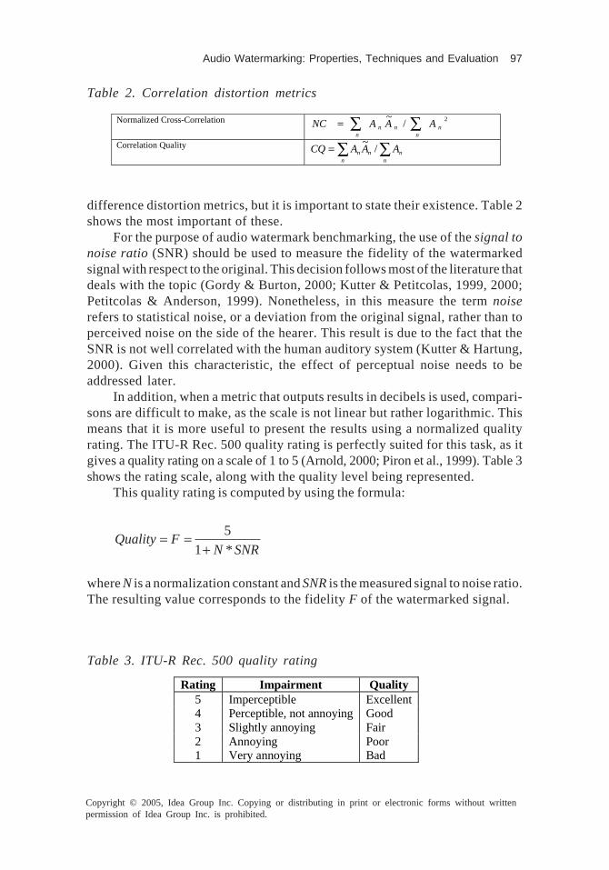
Audio Watermarking: Properties, Techniques and Evaluation 97
Copyright © 2005, Idea Group Inc. Copying or distributing in print or electronic forms without writtenpermission of Idea Group Inc. is prohibited.
difference distortion metrics, but it is important to state their existence. Table 2shows the most important of these.
For the purpose of audio watermark benchmarking, the use of the signal tonoise ratio (SNR) should be used to measure the fidelity of the watermarkedsignal with respect to the original. This decision follows most of the literature thatdeals with the topic (Gordy & Burton, 2000; Kutter & Petitcolas, 1999, 2000;Petitcolas & Anderson, 1999). Nonetheless, in this measure the term noiserefers to statistical noise, or a deviation from the original signal, rather than toperceived noise on the side of the hearer. This result is due to the fact that theSNR is not well correlated with the human auditory system (Kutter & Hartung,2000). Given this characteristic, the effect of perceptual noise needs to beaddressed later.
In addition, when a metric that outputs results in decibels is used, compari-sons are difficult to make, as the scale is not linear but rather logarithmic. Thismeans that it is more useful to present the results using a normalized qualityrating. The ITU-R Rec. 500 quality rating is perfectly suited for this task, as itgives a quality rating on a scale of 1 to 5 (Arnold, 2000; Piron et al., 1999). Table 3shows the rating scale, along with the quality level being represented.
This quality rating is computed by using the formula:
SNRNFQuality
*1
5
+==
where N is a normalization constant and SNR is the measured signal to noise ratio.The resulting value corresponds to the fidelity F of the watermarked signal.
Table 2. Correlation distortion metrics
Normalized Cross-Correlation ∑ ∑=n n
nnn AAANC2/
~
Correlation Quality ∑ ∑=n n
nnn AAACQ /~
Table 3. ITU-R Rec. 500 quality rating
Rating Impairment Quality 5 Imperceptible Excellent 4 Perceptible, not annoying Good 3 Slightly annoying Fair 2 Annoying Poor 1 Very annoying Bad
98 Garay Acevedo
Copyright © 2005, Idea Group Inc. Copying or distributing in print or electronic forms without writtenpermission of Idea Group Inc. is prohibited.
Data PayloadThe fidelity of a watermarked signal depends on the amount of embedded
information, the strength of the mark, and the characteristics of the host signal.This means that a comparison between different algorithms must be made underequal conditions. That is, while keeping the payload fixed, the fidelity must bemeasured on the same audio cover signal for all watermarking techniques beingevaluated.
However, the process just described constitutes a single measure event andwill not be representative of the characteristics of the algorithms being evalu-ated, as results can be biased depending on the chosen parameters. For thisreason, it is important to perform the tests using a variety of audio signals, withchanging size and nature (Kutter & Petitcolas, 2000). Moreover, the test shouldalso be repeated using different keys.
The amount of information that should be embedded is not easy todetermine, and depends on the application of the watermarking scheme. InKutter and Petitcolas (2000) a message length of 100 bits is used on their test ofimage watermarking systems as a representative value. However, some securewatermarking protocols might need a bigger payload value, as the watermark Wcould include a cryptographic signature for both the audio file A, and thewatermark message m in order to be more secure (Katzenbeisser & Veith,2002). Given this, it is recommended to use a longer watermark bitstream for thetest, so that a real world scenario is represented. A watermark size of 128 bitsis big enough to include two 56-bit signatures and a unique identification numberthat identifies the owner.
SpeedBesides fidelity, the content owner might be interested in the time it takes
for an algorithm to embed a mark (Gordy & Burton, 2000). Although speed isdependent on the type of implementation (hardware or software), one cansuppose that the evaluation will be performed on software versions of thealgorithms. In this case, it is a good practice to perform the test on a machine withsimilar characteristics to the one used by the end user (Petitcolas, 2000).Depending on the application, the value for the time it takes to embed awatermark will be incorporated into the results of the test. This will be done later,when all the measures are combined together.
MEASURING ROBUSTNESSWatermarks have to be able to withstand a series of signal operations that
are performed either intentionally or unintentionally on the cover signal and thatcan affect the recovery process. Given this, watermark designers try to

Audio Watermarking: Properties, Techniques and Evaluation 99
Copyright © 2005, Idea Group Inc. Copying or distributing in print or electronic forms without writtenpermission of Idea Group Inc. is prohibited.
guarantee a minimum level of robustness against such operations. Nonetheless,the concept of robustness is ambiguous most of the time and thus claims abouta watermarking scheme being robust are difficult to prove due to the lack oftesting standards (Craver, Perrig, & Petitcolas, 2000).
By defining a standard metric for watermark robustness, one can thenassure fairness when comparing different technologies. It becomes necessaryto create a detailed and thorough test for measuring the ability that a watermarkhas to withstand a set of clearly defined signal operations. In this section thesesignal operations are presented, and a practical measure for robustness isproposed.
How to MeasureBefore defining a metric, it must be stated that one does not need to erase
a watermark in order to render it useless. It is said that a watermarking schemeis robust when it is able to withstand a series of attacks that try to degrade thequality of the embedded watermark, up to the point where it is removed, or itsrecovery process is unsuccessful. This means that just by interfering with thedetection process a person can create a successful attack over the system, evenunintentionally.
However, in some cases one can overcome this characteristic by usingerror-correcting codes or a stronger detector (Cox et al., 2002). If an errorcorrection code is applied to the watermark message, then it is unnecessary toentirely recover the watermark W in order to successfully retrieve the embeddedmessage m. The use of stronger detectors can also be very helpful in thesesituations. For example, if a marking scheme has a publicly available detector,then an attacker will try to tamper with the cover signal up to the point where thedetector does not recognize the watermark’s presence14. Nonetheless, thecontent owner may have another version of the watermark detector, one that cansuccessfully recover the mark after some extra set of signal processingoperations. This “special” detector might not be released for public use foreconomic, efficiency or security reasons. For example, it might only be used incourt cases. The only thing that is really important is that it is possible to designa system with different detector strengths.
Given these two facts, it makes sense to use a metric that allows fordifferent levels of robustness, instead of one that only allows for two differentstates (the watermark is either robust or not). With this characteristic in mind,the basic procedure for measuring robustness is a three-step process, defined asfollows:
1. For each audio file in a determined test set embed a random watermark Won the audio signal A, with the maximum strength possible that does not

100 Garay Acevedo
Copyright © 2005, Idea Group Inc. Copying or distributing in print or electronic forms without writtenpermission of Idea Group Inc. is prohibited.
diminish the fidelity of the cover below a specified minimum (Petitcolas &Anderson, 1999).
2. Apply a set of relevant signal processing operations to the watermarkedaudio signal A'.
3. Finally, for each audio cover, extract the watermark W using the corre-sponding detector and measure the success of the recovery process.
Some of the early literature considered the recovery process successfulonly if the whole watermark message m was recovered (Petitcolas, 2000;Petitcolas & Anderson, 1999). This was in fact a binary robustness metric.However, the use of the bit-error rate has become common recently (Gordy &Burton, 2000; Kutter & Hartung, 2000; Kutter & Petitcolas, 2000), as it allowsfor a more detailed scale of values. The bit-error rate (BER) is defined as theratio of incorrect extracted bits to the total number of embedded bits and can beexpressed using the formula:
∑−
=
≠=
=1
0 ',0
',1100 l
n nn
nn
WW
WW
lBER
where l is the watermark length, Wn corresponds to the nth bit of the embedded
watermark and W'n corresponds to the nth bit of the recovered watermark. In
other words, this measure of robustness is the certainty of detection of theembedded mark (Arnold, 2000). It is easy to see why this measure makes moresense, and thus should be used as the metric when evaluating the success of thewatermark recovery process and therefore the robustness of an audiowatermarking scheme.
A final recommendation must be made at this point. The three-stepprocedure just described should be repeated several times, since the embeddedwatermark W is randomly generated and the recovery can be successful bychance (Petitcolas, 2000).
Up to this point no details have been given about the signal operations thatshould be performed in the second step of the robustness test. As a rule of thumb,one should include as a minimum the operations that the audio cover is expectedto go through in a real world application. However, this will not provide enoughtesting, as a malicious attacker will most likely have access to a wide range oftools as well as a broad range of skills. Given this situation, several scenariosshould be covered. In the following sections the most common signaloperations and attacks that an audio watermark should be able to withstand arepresented.

Audio Watermarking: Properties, Techniques and Evaluation 101
Copyright © 2005, Idea Group Inc. Copying or distributing in print or electronic forms without writtenpermission of Idea Group Inc. is prohibited.
Audio Restoration AttackAudio restoration techniques have been used for several years now,
specifically for restoring old audio recordings that have audible artifacts. In audiorestoration the recording is digitized and then analyzed for degradations. Afterthese degradations have been localized, the corresponding samples are elimi-nated. Finally the recording is reconstructed (that is, the missing samples arerecreated) by interpolating the signal using the remaining samples.
One can assume that the audio signal is the product of a stationaryautoregressive (AR) process of finite order (Petitcolas & Anderson, 1998). Withthis assumption in mind, one can use an audio segment to estimate a set of ARparameters and then calculate an approximate value for the missing samples.Both of the estimates are calculated using a least-square minimization technique.
Using the audio restoration method just described one can try to render awatermark undetectable by processing the marked audio signal A'. The processis as follows: First divide the audio signal A' into N blocks of size m samples each.A value of m=1000 samples has been proposed in the literature (Petitcolas &Anderson, 1999). A block of length l is removed from the middle of each blockand then restored using the AR audio restoration algorithm. This generates areconstructed block also of size m. After the N blocks have been processed theyare concatenated again, and an audio signal B' is produced. It is expected thatB' will be closer to A than to A' and thus the watermark detector will not find anymark in it.
An error free restoration is theoretically possible in some cases, but this isnot desired since it would produce a signal identical to A'. What is expected isto create a signal that has an error value big enough to mislead the watermarkdetector, but small enough to prevent the introduction of audible noise. Adjustingthe value of the parameter l controls the magnitude of the error (Petitcolas &Anderson, 1999). In particular, a value of l=80 samples has proven to give goodresults.
Invertibility AttackWhen resolving ownership cases in court, the disputing parties can both
claim that they have inserted a valid watermark on the audio file, as it issometimes possible to embed multiple marks on a single cover signal. Clearly,one mark must have been embedded before the other.
The ownership is resolved when the parties are asked to show the originalwork to court. If Alice has the original audio file A, which has been kept storedin a safe place, and Mallory has a counterfeit original file Ã, which has beenderived from A, then Alice can search for her watermark W in Mallory’s file andwill most likely find it. The converse will not happen, and the case will be resolved(Craver et al., 2000). However, an attack to this procedure can be created, andis known as an invertibility attack.
102 Garay Acevedo
Copyright © 2005, Idea Group Inc. Copying or distributing in print or electronic forms without writtenpermission of Idea Group Inc. is prohibited.
Normally the content owner adds a watermark W to the audio file A,creating a watermarked audio file A' = A+W, where the sign “+” denotes theembedding operation. This file is released to the public, while the original A andthe watermark W are stored in a safe place. When a suspicious audio file Ã
appears, the difference � ���� � � is computed. This difference should be equalto W if A' and à are equal, and very close to W if à was derived from A'. In
general, a correlation function ƒ(W, �� ) is used to determine the similarity
between the watermark W and the extracted data �� . This function will yield
a value close to 1, if W and �� are similar.However, Mallory can do the following: she can subtract (rather than add)
a second watermark w from Alice’s watermarked file A', using the inverse of theembedding algorithm. This yields an audio file  = A'- w = A + W- w, whichMallory can now claim to be the original audio file, along with w as the originalwatermark (Craver, Memon, Yeo, & Yeung, 1998). Now both Alice and Mallorycan claim copyright violation from their counterparts.
When the two originals are compared in court, Alice will find that herwatermark is present in Mallory’s audio file, since  – A = W-w is calculated, andƒ(W-w, W) ≈ 1. However, Mallory can show that when A –  = w -W is calculated,then ƒ(w -W, w) ≈ 1 as well. In other words, Mallory can show that her mark isalso present in Alice’s work, even though Alice has kept it locked at all times(Craver, Memon, & Yeung, 1996; Craver, Yeo et al., 1998). Given the symmetryof the equations, it is impossible to decide who is the real owner of the originalfile. A deadlock is thus created (Craver, Yeo et al., 1998; Pereira et al., 2001).
This attack is a clear example of how one can render a mark unusablewithout having to remove it, by exploiting the invertibility of the watermarkingmethod, which allows an attacker to remove as well as add watermarks. Suchan attack can be prevented by using a non-invertible cryptographic signature inthe watermark W; that is, using a secure watermarking protocol (Katzenbeisser& Veith, 2002; Voloshynovskiy, Pereira, Pun et al., 2001).
Specific Attack on Echo WatermarkingThe echo watermarking technique presented in this chapter can be easily
“attacked” simply by detecting the echo and then removing the delayed signal byinverting the convolution formula that was used to embed it. However, theproblem consists of detecting the echo without knowing the original signal andthe possible delay values. This problem is referred to as blind echo cancella-tion, and is known to be difficult to solve (Petitcolas, Anderson, & G., 1998).Nonetheless, a practical solution to this problem appears to lie in the samefunction that is used for echo watermarking extraction: cepstrum autocorrelation.Cepstrum analysis, along with a brute force search can be used together to findthe echo signal in the watermarked audio file A'.
^
^
^
^
^
^^
^ ^
Audio Watermarking: Properties, Techniques and Evaluation 103
Copyright © 2005, Idea Group Inc. Copying or distributing in print or electronic forms without writtenpermission of Idea Group Inc. is prohibited.
A detailed description of the attack is given by Craver et al. (2000), and theidea is as follows: If we take the power spectrum of A'(t) = A(t) + αA(t – ∆t),denoted by Φ and then calculate the logarithm of Φ, the amplitude of the delayedsignal can be augmented using an autocovariance function15 over the powerspectrum Φ'(ln(Φ)). Once the amplitude has been increased, then the “hump”of the signal becomes more visible and the value of the delay ∆t can bedetermined (Petitcolas et al., 1998).
Experiments show that when an artificial echo is added to the signal, thisattack works well for values of ∆t between 0.5 and three milliseconds (Craveret al., 2000). Given that the watermark is usually embedded with a delay valuethat ranges from 0.5 to two milliseconds, this attack seems to be well suited forthe technique and thus very likely to be successful (Petitcolas et al., 1999).
Collusion AttackA collusion attack, also known as averaging, is especially effective against
basic fingerprinting schemes. The basic idea is to take a large number ofwatermarked copies of the same audio file, and average them in order to producean audio signal without a detectable mark (Craver et al., 2000; Kirovski &Malvar, 2001).
Another possible scenario is to have copies of multiple works that have beenembedded with the same watermark. By averaging the sample values of theaudio signals, one could estimate the value of the embedded mark, and then tryto subtract it from any of the watermarked works. It has been shown that a smallnumber (around 10) of different copies are needed in order to perform asuccessful collusion attack (Voloshynovskiy, Pereira, Pun et al., 2001). Anobvious countermeasure to this attack is to embed more than one mark on eachaudio cover, and to make the marks dependant on the characteristics of the audiofile itself (Craver et al., 2000).
Signal Diminishment Attacks and Common ProcessingOperations
Watermarks must be able to survive a series of signal processing operationsthat are commonly performed on the audio cover work, either intentionally orunintentionally. Any manipulation of an audio signal can result in a successfulremoval of the embedded mark. Furthermore, the availability of advanced audioediting tools on the Internet, such as Audacity (Dannenberg & Mazzoni, 2002),implies that these operations can be performed without an extensive knowledgeof digital signal processing techniques. The removal of a watermark by perform-ing one of these operations is known as a signal diminishment attack, andprobably constitutes the most common attack performed on digital watermarks(Meerwald & Pereira, 2002).
104 Garay Acevedo
Copyright © 2005, Idea Group Inc. Copying or distributing in print or electronic forms without writtenpermission of Idea Group Inc. is prohibited.
Given this, a set of the most common signal operations must be specified,and watermark resistance to these must be evaluated. Even though an audio filewill most likely not be subject to all the possible operations, a thorough list isnecessary. Defining which subset of these operations is relevant for a particularwatermarking scheme is a task that needs to be done; however, this will beaddressed later in the chapter.
The signal processing operations presented here are classified into eightdifferent groups, according to the presentation made in Petitcolas et al. (2001).These are:
• Dynamics. These operations change the loudness profile of the audiosignal. The most basic way of performing this consists of increasing ordecreasing the loudness directly. More complicated operations includelimiting, expansion and compression, as they constitute nonlinear operationsthat are dependant on the audio cover.
• Filter. Filters cut off or increase a selected part of the audio spectrum.Equalizers can be seen as filters, as they increase some parts of thespectrum, while decreasing others. More specialized filters include low-pass, high-pass, all-pass, FIR, and so forth.
• Ambience. These operations try to simulate the effect of listening to anaudio signal in a room. Reverb and delay filters are used for this purpose,as they can be adjusted in order to simulate the different sizes andcharacteristics that a room can have.
• Conversion. Digital audio files are nowadays subject to format changes.For example, old monophonic signals might be converted to stereo formatfor broadcast transmission. Changes from digital to analog representationand back are also common, and might induce significant quantization noise,as no conversion is perfect.
• Lossy compression algorithms are becoming popular, as they reduce theamount of data needed to represent an audio signal. This means that lessbandwidth is needed to transmit the signal, and that less space is needed forits storage. These compression algorithms are based on psychoacousticmodels and, although different implementations exist, most of them rely ondeleting information that is not perceived by the listener. This can pose aserious problem to some watermarking schemes, as they sometimes willhide the watermark exactly in these imperceptible regions. If thewatermarking algorithm selects these regions using the same method as thecompression algorithm, then one just needs to apply the lossy compressionalgorithm to the watermarked signal in order to remove the watermark.
• Noise can be added in order to remove a watermark. This noise can evenbe imperceptible, if it is shaped to match the properties of the cover signal.Fragile watermarks are especially vulnerable to this attack. Sometimes

Audio Watermarking: Properties, Techniques and Evaluation 105
Copyright © 2005, Idea Group Inc. Copying or distributing in print or electronic forms without writtenpermission of Idea Group Inc. is prohibited.
noise will appear as the product of other signal operations, rather thanintentionally.
• Modulation effects like vibrato, chorus, amplitude modulation and flangingare not common post-production operations. However, they are included inmost of the audio editing software packages and thus can be easily used inorder to remove a watermark.
• Time stretch and pitch shift. These operations either change the length ofan audio passage without changing its pitch, or change the pitch withoutchanging its length in time. The use of time stretch techniques has becomecommon in radio broadcasts, where stations have been able to increase thenumber of advertisements without devoting more air time to these (Kuczynski,2000).
• Sample permutations. This group consists of specialized algorithms foraudio manipulation, such as the attack on echo hiding just presented.Dropping of some samples in order to misalign the watermark decoder isalso a common attack to spread-spectrum watermarking techniques.
It is not always clear how much processing a watermark should be able towithstand. That is, the specific parameters of the diverse filtering operations thatcan be performed on the cover signal are not easy to determine. In general termsone could expect a marking scheme to be able to survive several processingoperations up to the point where they introduce annoying audible effects on theaudio work. However, this rule of thumb is still too vague.
Fortunately, guidelines and minimum requirements for audio watermarkingschemes have been proposed by different organizations such as the SecureDigital Music Initiative (SDMI), International Federation of the PhonographicIndustry (IFPI), and the Japanese Society for Rights of Authors, Composers andPublishers (JASRAC). These guidelines constitute the baseline for any robust-ness test. In other words, they describe the minimum processing that an audiowatermark should be able to resist, regardless of its intended application. Table4 summarizes these requirements (JASRAC, 2001; SDMI, 2000).
False PositivesWhen testing for false positives, two different scenarios must be evaluated.
The first one occurs when the watermark detector signals the presence of a markon an unmarked audio file. The second case corresponds to the detectorsuccessfully finding a watermark W' on an audio file that has been marked witha watermark W (Cox et al., 2002; Kutter & Hartung, 2000; Petitcolas et al.,2001).
The testing procedure for both types of false positives is simple. In the firstcase one just needs to run the detector on a set of unwatermarked works. Forthe second case, one can embed a watermark W using a given key K, and then

106 Garay Acevedo
Copyright © 2005, Idea Group Inc. Copying or distributing in print or electronic forms without writtenpermission of Idea Group Inc. is prohibited.
try to extract a different mark W' while using the same key K. The false positiverate (FPR) is then defined as the number of successful test runs divided by thetotal number of test runs. A successful test run is said to occur whenever a falsepositive is detected.
However, a big problem arises when one takes into account the requiredfalse positive rate for some schemes. For example, a popular application such asDVD watermarking requires a false positive rate of 1 in 1012 (Cox et al., 2002).In order to verify that this rate is accomplished one would need to run thedescribed experiment during several years. Other applications such as proof ofownership in court are rare, and thus require a lower false positive rate.Nonetheless, a false rate probability of 10-6, required for the mentioned applica-tion, can be difficult to test.
MEASURING PERCEPTIBILITYDigital content consumers are aware of many aspects of emerging
watermarking technologies. However, only one prevails over all of them: usersare concerned with the appearance of perceptible (audible) artifacts due to theuse of a watermarking scheme. Watermarks are supposed to be imperceptible(Cox et al., 2002). Given this fact, one must carefully measure the amount of
Processing Operation Requirements Digital to analog conversion Two consecutive digital to analog and analog to digital conversions. Equalization 10 band graphic equalizer with the following characteristics:
Freq. (Hz)
31 62 125 250 500 1k 2k 4k 8k 16k
Gain (db)
-6 +6 -6 +3 -6 +6 -6 +6 -6 +6
Band-pass filtering 100 Hz – 6 kHz, 12dB/oct. Time stretch and pitch change +/- 10% compression and decompression. Codecs (at typically used data rates)
AAC, MPEG-4 AAC with perceptual noise substitution, MPEG-1 Audio Layer 3, Q-Design, Windows Media Audio, Twin-VQ, ATRAC-3, Dolby Digital AC-3, ePAC, RealAudio, FM, AM, PCM.
Noise addition Adding white noise with constant level of 40dB lower than total averaged music power (SNR: 40dB).
Time scale modification Pitch invariant time scaling of +/- 4%. Wow and flutter 0.5% rms, from DC to 250Hz. Echo addition Delay up to 100 milliseconds, feedback coefficient up to 0.5. Down mixing and surround sound processing
Stereo to mono, 6 channel to stereo, SRS, spatializer, Dolby surround, Dolby headphone.
Sample rate conversion 44.1 kHz to 16 kHz, 48 kHz to 44.1 kHz, 96 kHz to 48/44.1 kHz. Dynamic range reduction Threshold of 50dB, 16dB maximum compression.
Rate: 10-millisecond attack, 3-second recovery. Amplitude compression 16 bits to 8 bits.
Table 4. Summary of SDMI, STEP and IFPI requirements
Audio Watermarking: Properties, Techniques and Evaluation 107
Copyright © 2005, Idea Group Inc. Copying or distributing in print or electronic forms without writtenpermission of Idea Group Inc. is prohibited.
distortion that the listener will perceive on a watermarked audio file, as comparedto its unmarked counterpart. Formal listening tests have been considered the onlyrelevant method for judging audio quality, as traditional objective measures suchas the signal-to-noise ratio (SNR) or total-harmonic-distortion16 (THD) havenever been shown to reliably relate to the perceived audio quality, as they cannot be used to distinguish inaudible artifacts from audible noise (ITU, 2001;Kutter & Hartung, 2000; Thiede & Kabot, 1996). There is a need to adopt anobjective measurement test for perceptibility of audio watermarking schemes.
Furthermore, one must be careful, as perceptibility must not be viewed asa binary condition (Arnold & Schilz, 2002; Cox et al., 2002). Different levels ofperceptibility can be achieved by a watermarking scheme; that is, listeners willperceive the presence of the watermark in different ways. Auditory sensitivitiesvary significantly from individual to individual. As a consequence, any measureof perceptibility that is not binary should accurately reflect the probability of thewatermark being detected by a listener.
In this section a practical and automated evaluation of watermark percep-tibility is proposed. In order to do so, the human auditory system (HAS) is firstdescribed. Then a formal listening test is presented, and finally a psychoacousticalmodel for automation of such a procedure is outlined.
Human Auditory System (HAS)Figure 4, taken from Robinson (2002), presents the physiology of the human
auditory system. Each one of its components is now described.The pinna directionally filters incoming sounds, producing a spectral
coloration known as head related transfer function (or HRTF). This functionenables human listeners to localize the sound source in three dimensions.
The ear canal filters the sound, attenuating both low and high frequencies.As a result, a resonance arises around 5 kHz. After this, small bones known asthe timpanic membrane (or ear drum), malleus and incus transmit the soundpressure wave through the middle ear. The outer and middle ear perform a bandpass filter operation on the input signal.
The sound wave arrives at the fluid-filled cochlea, a coil within the ear thatis partially protected by a bone. Inside the cochlea resides the basilar membrane(BM), which semi-divides it. The basilar membrane acts as a spectrum analyzer,as it divides the signal into frequency components. Each point on the membraneresonates at a different frequency, and the spacing of these resonant frequenciesalong the BM is almost logarithmic. The effective frequency selectivity is relatedto the width of the filter characteristic at each point.
The outer hair cells, distributed along the length of the BM, react tofeedback from the brainstem. They alter their length to change the resonantproperties of the BM. As a consequence, the frequency response of themembrane becomes amplitude dependent.

108 Garay Acevedo
Copyright © 2005, Idea Group Inc. Copying or distributing in print or electronic forms without writtenpermission of Idea Group Inc. is prohibited.
Finally, the inner hair cells of the basilar membrane fire when the BM movesupward. In doing so, they transduce the sound wave at each point into a signalon the auditory nerve. In this way the signal is half wave rectified. Each cellneeds a certain time to recover between successive firings, so the averageresponse during a steady tone is lower than at its onset. This means that the innerhair cells act as an automatic gain control.
The net result of the process described above is that an audio signal, whichhas a relatively wide-bandwidth, and large dynamic range, is encoded fortransmission along the nerves. Each one of these nerves offers a much narrowerbandwidth, and limited dynamic range. In addition, a critical process hashappened during these steps. Any information that is lost due to the transductionprocess within the cochlea is not available to the brain. In other words, thecochlea acts as a lossy coder. The vast majority of what we cannot hear isattributable to this transduction process (Robinson & Hawksford, 1999).
Detailed modeling of the components and processes just described will benecessary when creating an auditory model for the evaluation of watermarkedaudio. In fact, by representing the audio signal at the basilar membrane, one caneffectively model what is effectively perceived by a human listener.
Perceptual PhenomenaAs was just stated, one can model the processes that take place inside the
HAS in order to represent how a listener responds to auditory stimuli. Given itscharacteristics, the HAS responds differently depending on the frequency andloudness of the input. This means that all components of a watermark may notbe equally perceptible. Moreover, it also denotes the need of using a perceptualmodel to effectively measure the amount of distortion that is imposed on an audiosignal when a mark is embedded. Given this fact, in this section the mainprocesses that need to be included on a perceptual model are presented.
Sensitivity refers to the ear’s response to direct stimuli. In experimentsdesigned to measure sensitivity, listeners are presented with isolated stimuli andtheir perception of these stimuli is tested. For example, a common test consistsof measuring the minimum sound intensity required to hear a particular frequency
Figure 4. Overview of the human auditory system (HAS)

Audio Watermarking: Properties, Techniques and Evaluation 109
Copyright © 2005, Idea Group Inc. Copying or distributing in print or electronic forms without writtenpermission of Idea Group Inc. is prohibited.
(Cox et al., 2002). The main characteristics measured for sensitivity arefrequency and loudness.
The responses of the HAS are frequency dependent; variations in fre-quency are perceived as different tones. Tests show that the ear is most sensitiveto frequencies around 3kHz and that sensitivity declines at very low (20 Hz) andvery high (20 kHz) frequencies.
Regarding loudness, different tests have been performed to measuresensitivity. As a general result, one can state that the HAS is able to discernsmaller changes when the average intensity is louder. In other words, the humanear is more sensitive to changes in louder signals than in quieter ones.
The second phenomenon that needs to be taken into account is masking. Asignal that is clearly audible if presented alone can be completely inaudible in thepresence of another signal, the masker. This effect is known as masking, and themasked signal is called the maskee. For example, a tone might become inaudiblein the presence of a second tone at a nearby frequency that is louder. In otherwords, masking is a measure of a listener’s response to one stimulus in thepresence of another.
Two different kinds of masking can occur: simultaneous masking andtemporal masking (Swanson et al., 1998). In simultaneous masking, both themasker and the maskee are presented at the same time and are quasi-stationary(ITU, 2001). If the masker has a discrete bandwidth, the threshold of hearing israised even for frequencies below or above the masker. In the situation wherea noise-like signal is masking a tonal signal, the amount of masking is almostfrequency independent; if the sound pressure of the maskee is about 5 dB belowthat of the masker, then it becomes inaudible. For other cases, the amount ofmasking depends on the frequency of the masker.
In temporal masking, the masker and the maskee are presented at differenttimes. Shortly after the decay of a masker, the masked threshold is closer tosimultaneous masking of this masker than to the absolute threshold (ITU, 2001).Depending on the duration of the masker, the decay time of the threshold canvary between five ms and 150 ms. Furthermore, weak signals just before loudsignals are masked. The duration of this backward masking effect is about five ms.
The third effect that has to be considered is pooling. When multiplefrequencies are changed rather than just one, it is necessary to know how tocombine the sensitivity and masking information for each frequency. Combiningthe perceptibilities of separate distortions gives a single estimate for the overallchange in the work. This is known as pooling. In order to calculate thisphenomenon, it is common to apply the formula:
1
( , ') | [ ] |p
p
i
D A A d i = ∑

110 Garay Acevedo
Copyright © 2005, Idea Group Inc. Copying or distributing in print or electronic forms without writtenpermission of Idea Group Inc. is prohibited.
where d[i] is an estimate of the likelihood that an individual will notice thedifference between A and A' in a temporal sample (Cox et al., 2002). In the caseof audio, a value of p=1 is sometimes appropriate, which turns the equation intoa linear summation.
ABX Listening TestAudio quality is usually evaluated by performing a listening test. In particu-
lar, the ABX listening test is commonly used when evaluating the quality ofwatermarked signals. Other tests for audio watermark quality evaluation, suchas the one described in Arnold and Schilz (2002), follow a similar methodologyas well. Given this, it becomes desirable to create an automatic model thatpredicts the response observed from a human listener in such a procedure.
In an ABX test the listener is presented with three different audio clips:selection A (in this case the non-watermarked audio), selection B (the watermarkedaudio) and X (either the watermarked or non-watermarked audio), drawn atrandom. The listener is then asked to decide if selection X is equal to A or B. Thenumber of correct answers is the basis to decide if the watermarked audio isperceptually different than the original audio and one will, therefore, declare thewatermarking algorithm as “perceptible”. In the other case, if the watermarkedaudio is perceptually equal to the original audio, the watermarking algorithm willbe declared as transparent, or imperceptible. In the particular case of Arnoldand Schilz (2002), the level of transparency is assumed to be determined by thenoise-to-mask ratio (NMR).
The ABX test is fully described in ITU Recommendation ITU-R BS.1116,and has been successfully used for subjective measurement of impaired audiosignals. Normally only one attribute is used for quality evaluation. It is alsodefined that this attribute represents any and all detected differences betweenthe original signal and the signal under test. It is known as basic audio quality(BAQ), and is calculated as the difference between the grade given to theimpaired signal and the grade given to the original signal. Each one of thesegrades uses the five-level impairment scale that was presented previously. Giventhis fact, values for the BAQ range between 0 and -4, where 0 corresponds toan imperceptible impairment and -4 to one judged as very annoying.
Although its results are highly reliable, there are many problems related toperforming an ABX test for watermark quality evaluation. One of them is thesubjective nature of the test, as the perception conditions of the listener may varywith time. Another problem arises from the high costs associated with the test.These costs include the setup of audio equipment17, construction of a noise-freelistening room, and the costs of employing individuals with extraordinarily acutehearing. Finally, the time required to perform extensive testing also poses aproblem to this alternative.
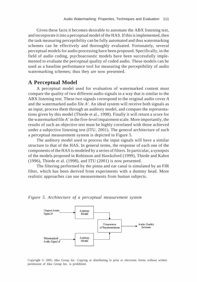
Audio Watermarking: Properties, Techniques and Evaluation 111
Copyright © 2005, Idea Group Inc. Copying or distributing in print or electronic forms without writtenpermission of Idea Group Inc. is prohibited.
Given these facts it becomes desirable to automate the ABX listening test,and incorporate it into a perceptual model of the HAS. If this is implemented, thenthe task measuring perceptibility can be fully automated and thus watermarkingschemes can be effectively and thoroughly evaluated. Fortunately, severalperceptual models for audio processing have been proposed. Specifically, in thefield of audio coding, psychoacoustic models have been successfully imple-mented to evaluate the perceptual quality of coded audio. These models can beused as a baseline performance tool for measuring the perceptibility of audiowatermarking schemes; thus they are now presented.
A Perceptual ModelA perceptual model used for evaluation of watermarked content must
compare the quality of two different audio signals in a way that is similar to theABX listening test. These two signals correspond to the original audio cover Aand the watermarked audio file A'. An ideal system will receive both signals asan input, process them through an auditory model, and compare the representa-tions given by this model (Thiede et al., 1998). Finally it will return a score forthe watermarked file A' in the five-level impairment scale. More importantly, theresults of such an objective test must be highly correlated with those achievedunder a subjective listening test (ITU, 2001). The general architecture of sucha perceptual measurement system is depicted in Figure 5.
The auditory model used to process the input signals will have a similarstructure to that of the HAS. In general terms, the response of each one of thecomponents of the HAS is modeled by a series of filters. In particular, a synopsisof the models proposed in Robinson and Hawksford (1999), Thiede and Kabot(1996), Thiede et al. (1998), and ITU (2001) is now presented.
The filtering performed by the pinna and ear canal is simulated by an FIRfilter, which has been derived from experiments with a dummy head. Morerealistic approaches can use measurements from human subjects.
Figure 5. Architecture of a perceptual measurement system
112 Garay Acevedo
Copyright © 2005, Idea Group Inc. Copying or distributing in print or electronic forms without writtenpermission of Idea Group Inc. is prohibited.
After this prefiltering, the audio signal has to be converted to a basilarmembrane representation. That is, the amplitude dependent response of thebasilar membrane needs to be simulated. In order to do this, the first step consistsof processing the input signal through a bank of amplitude dependant filters, eachone adapted to the frequency response of a point on the basilar membrane. Thecenter frequency of each filter should be linearly spaced on the Bark scale, acommonly used frequency scale18. The actual number of filters to be useddepends on the particular implementation. Other approaches might use a fastFourier transform to decompose the signal, but this creates a trade-off betweentemporal and spectral resolution (Thiede & Kabot, 1996).
At each point in the basilar membrane, its movement is transduced into anelectrical signal by the hair cells. The firing of individual cells is pseudorandom,but when the individual signals are combined, the proper motion of the BM isderived. Simulating the individual response of each hair cell and combining theseresponses is a difficult task, so other practical solutions have to be applied. Inparticular, Robinson and Hawksford (1999) implement a solution based oncalculating the half wave response of the cells, and then using a series offeedback loops to simulate the increased sensitivity of the inner hair cells to theonset of sounds. Other schemes might just convolve the signal with a spreadingfunction, to simulate the dispersion of energy along the basilar membrane, andthen convert the signal back to decibels (ITU, 2001). Independently of themethod used, the basilar membrane representation is obtained at this point.
After a basilar membrane representation has been obtained for both theoriginal audio signal A, and the watermarked audio signal A', the perceiveddifference between the two has to be calculated. The difference between thesignals at each frequency band has to be calculated, and then it must bedetermined at what level these differences will become audible for a humanlistener (Robinson & Hawksford, 1999). In the case of the ITU Recommenda-tion ITU-R BS.1387, this task is done by calculating a series of model variables,such as excitation, modulation and loudness patterns, and using them as an inputto an artificial neural network with one hidden layer (ITU, 2001). In the modelproposed in Robinson and Hawksford (1999), this is done as a summation overtime (over an interval of 20 ms) along with weighting of the signal and peaksuppression.
The result of this process is an objective difference between the two signals.In the case of the ITU model, the result is given in a negative five-levelimpairment scale, just like the BAQ, and is known as the objective differencegrade (ODG). For other models, the difference is given in implementation-dependant units. In both cases, a mapping or scaling function, from the modelunits to the ITU-R. 500 scale, must be used.
For the ITU model, this mapping could be trivial, as all that is needed is toadd a value of five to the value of the ODG. However, a more precise mapping

Audio Watermarking: Properties, Techniques and Evaluation 113
Copyright © 2005, Idea Group Inc. Copying or distributing in print or electronic forms without writtenpermission of Idea Group Inc. is prohibited.
function could be developed. The ODG has a resolution of one decimal, and themodel was not specifically designed for the evaluation watermarking schemes.Given this, a nonlinear mapping (for example using a logarithmic function) couldbe more appropriate.
For other systems, determining such a function will depend on the particularimplementation of the auditory model; nonetheless such a function should exist,as a correlation between objective and subjective measures was stated as aninitial requirement. For example, in the case of Thiede and Kabot (1996), asigmoidal mapping function is used. Furthermore, the parameters for themapping function can be calculated using a control group consisting of widelyavailable listening test data.
The resulting grade, in the five-level scale, is defined as the perceptibility ofthe audio watermark. This means that in order to estimate the perceptibility ofthe watermarking scheme, several test runs must be performed. Again, thesetest runs should embed a random mark on a cover signal, and a large andrepresentative set of audio cover signals must be used. The perceptibility testscore is finally calculated by averaging the different results obtained for each oneof the individual tests.
FINAL BENCHMARK SCOREIn the previous sections, three different testing procedures have been
proposed, in order to measure the fidelity, robustness and perceptibility of awatermarking scheme. Each one of these tests has resulted in several scores,some of which may be more useful than others. In this section, these scores arecombined in order to obtain a final benchmarking score. As a result, faircomparison amongst competing technologies is possible, as the final watermarkingscheme evaluation score is obtained.
In addition, another issue is addressed at this point: defining the specificparameters to be used for each attack while performing the robustness test.While the different attacks were explained in the sixth section, the strength atwhich they should be applied was not specified. As a general rule of thumb, it wasjust stated that these operations should be tested up to the point where noticeabledistortion is introduced on the audio cover file.
As it has been previously discussed, addressing these two topics can proveto be a difficult task. Moreover, a single answer might not be appropriate forevery possible watermarking application. Given this fact, one should develop anduse a set of application-specific evaluation templates to overcome this restric-tion. In order to do so, an evaluation template is defined as a set of guidelinesthat specifies the specific parameters to be used for the different tests per-formed, and also denotes the relative importance of each one of the testsperformed on the watermarking scheme. Two fundamental concepts have been
114 Garay Acevedo
Copyright © 2005, Idea Group Inc. Copying or distributing in print or electronic forms without writtenpermission of Idea Group Inc. is prohibited.
incorporated into that of evaluation templates: evaluation profiles and applicationspecific benchmarking.
Evaluation profiles have been proposed in Petitcolas (2000) as a methodfor testing different levels of robustness. Their sole purpose is to establish the setof tests and media to be used when evaluating a marking algorithm. For example,Table 4, which summarizes the robustness requirements imposed by variousorganizations, constitutes a general-purpose evaluation profile. More specificprofiles have to be developed when evaluating more specific watermarkingsystems. For example, one should test a marking scheme intended for advertise-ment broadcast monitoring with a set of recordings similar to those that will beused in a real world situation. There is no point in testing such an algorithm witha set of high-fidelity musical recordings. Evaluation profiles are thus a part of theproposed evaluation templates.
Application specific benchmarking, in turn, is proposed in Pereira et al.(2001) and Voloshynovskiy, Pereira, Iquise and Pun (2001) and consists ofaveraging the results of the different tests performed to a marking scheme, usinga set of weights that is specific to the intended application of the watermarkingalgorithm. In other words, attacks are weighted as a function of applications(Pereira et al., 2001). In the specific case of the evaluation templates proposedin this document, two different sets of weights should be specified: those usedwhen measuring one of the three fundamental characteristics of the algorithm(i.e., fidelity, robustness and perceptibility); and those used when combiningthese measures into a single benchmarking score.
After the different weights have been established, the overall watermarkingscheme score is calculated as a simple weighted average, with the formula:
* * *f f r r p pScore w s w s w s= + +
where w represents the assigned weight for a test, s to the score received on atest, and the subscripts f, r, p denote the fidelity, robustness and perceptibilitytests respectively. In turn, the values of s
f, s
r, and s
p are also determined using
a weighted average for the different measures obtained on the specific subtests.The use of an evaluation template is a simple, yet powerful idea. It allows
for a fair comparison of watermarking schemes, and for ease of automatedtesting. After these templates have been defined, one needs only to select theintended application of the watermarking scheme that is to be evaluated, and therest of the operations can be performed automatically. Nonetheless, time has tobe devoted to the task of carefully defining the set of evaluation templates for thedifferent applications sought to be tested. A very simple, general-purposeevaluation template is shown next, as an example.

Audio Watermarking: Properties, Techniques and Evaluation 115
Copyright © 2005, Idea Group Inc. Copying or distributing in print or electronic forms without writtenpermission of Idea Group Inc. is prohibited.
Presenting the ResultsThe main result of the benchmark presented here is the overall watermarking
scheme score that has just been explained. It corresponds to a single, numericalresult. As a consequence, comparison between similar schemes is both quick andeasy. Having such a comprehensive quality measure is sufficient in most cases.
Under some circumstances the intermediate scores might also be important,as one might want to know more about the particular characteristics of a
Application: General Purpose Audio Watermarking Final Score Weights: Fidelity = 1/3, Robustness = 1/3, Perceptibility = 1/3
FIDELITY TEST Measure Parameters Weight
Quality N/A 0.75 Data Payload Watermark length = 100 bits, score calculated as BER. 0.125 Speed Watermark length = 50 bits, score calculated as 1 if embedding time is
less than 2 minutes, 0 otherwise. 0.125
ROBUSTNESS TEST Measure Parameters Weight
D/A Conversion D/A ? A/D twice. 1/14 Equalization 10 band graphic equalizer with the following characteristics:
Freq. (Hz)
31 62 125 250 500 1k 2k 4k 8k 16k
Gain (db)
-6 +6 -6 +3 -6 +6 -6 +6 -6 +6
1/14
Band-pass filtering
100 Hz – 6 kHz, 12dB/oct. 1/14
Time stretch and pitch change
+/- 10% compression and decompression 1/14
Codecs AAC, MPEG-4 AAC with perceptual noise substitution, MPEG-1 Audio Layer 3, Windows Media Audio, and Twin-VQ at 128 kbps.
1/14
Noise addition Adding white noise with constant level of 40dB lower than total averaged music power (SNR: 40dB)
1/14
Time scale modification
Pitch invariant time scaling of +/- 4% 1/14
Wow and flutter 0.5% rms, from DC to 250Hz 1/14 Echo addition Delay = 100 milliseconds, feedback coefficient = 0.5 1/14 Down mixing Stereo to mono, and Dolby surround 1/14 Sample rate conversion
44.1 kHz to 16 kHz 1/14
Dynamic range reduction
Threshold of 50dB, 16dB maximum compression Rate: 10 millisecond attack, 3 second recovery
1/14
Amplitude compression
16 bits to 8 bits 1/14
PERCEPTIBILITY TEST Measure Parameters Weight
Watermark perceptibility
N/A 1
↔

116 Garay Acevedo
Copyright © 2005, Idea Group Inc. Copying or distributing in print or electronic forms without writtenpermission of Idea Group Inc. is prohibited.
For example, one might just be interested in the perceptibility score of the echowatermarking algorithm, or in the robustness against uniform noise for twodifferent schemes. For these cases, the use of graphs, as proposed in Kutter andHartung (2000) and Kutter and Petitcolas (1999, 2000) is recommended.
The graphs should plot the variance in two different parameters, with theremaining parameters fixed. That is, the test setup conditions should remainconstant along different test runs. Finally, several test runs should be performed,and the results averaged. As a consequence, a set of variable and fixedparameters for performing the comparisons are possible, and thus several graphscan be plotted. Some of the most useful graphs, based on the discussionpresented in Kutter and Petitcolas (1999), along with their correspondingvariables and constants, are summarized in Table 5.
Of special interest to some watermark developers is the use of receiveroperating characteristic (ROC) graphs, as they show the relation between falsepositives and false negatives for a given watermarking system. “They are usefulfor assessing the overall behavior and reliability of the watermarking schemebeing tested” (Petitcolas & Anderson, 1999).
In order to understand ROC graphs, one should remember that a watermarkdecoder can be viewed as a system that performs two different steps: first itdecides if a watermark is present on the audio signal A’, and then it tries torecover the embedded watermark W. The first step can be viewed as a form ofhypothesis testing (Kutter & Hartung, 2000), where the decoder decidesbetween the alternative hypothesis (a watermark is present), and the nullhypothesis (the watermark is not present). Given these two options, two differenterrors can occur, as was stated in the third section: a false positive, and a falsenegative.
ROC graphs plot the true positive fraction (TPF) on the Y-axis, and the falsepositive fraction (FPF) on the X-axis. The TPF is defined by the formula:
TPTPF
TP FN=
+
Table 5. Useful graphs when evaluating a specific watermarking scheme
Graph Type Perceptual Quality
Robustness Measure
Strength of a Specific Attack
Data Payload
Robustness to an attack
fixed variable variable fixed
Perceptual Quality vs. Payload
variable fixed Fixed variable
Attack strength vs. Perceptual Quality
variable fixed variable fixed
ROC fixed fixed fixed/variable fixed

Audio Watermarking: Properties, Techniques and Evaluation 117
Copyright © 2005, Idea Group Inc. Copying or distributing in print or electronic forms without writtenpermission of Idea Group Inc. is prohibited.
where TP is the number of true positive test results, and FN is the number of falsenegative tests. Conversely, the FPF is defined by:
FPFPF
TN FP=
+
where TN is the number of false-positive results, and FP the number of truenegative results. An optimal detector will have a curve that goes from the bottomleft corner to the top left, and then to the top right corner (Kutter & Petitcolas,2000). Finally, it must be stated that the same number of watermarked andunwatermarked audio samples should be used for the test, although false-positive testing can be time-consuming, as was previously discussed in thisdocument.
Automated EvaluationThe watermarking benchmark proposed here can be implemented for the
automated evaluation of different watermarking schemes. In fact, this idea hasbeen included in test design, and has motivated some key decisions, such as theuse of a computational model of the ear instead of a formal listening test.Moreover, the establishment of an automated test for watermarking systems isan industry need. This assertion is derived from the following fact: to evaluatethe quality of a watermarking scheme one can do one of the following threeoptions (Petitcolas, 2000):
• Trust the watermark developer and his or her claims about watermarkperformance.
• Thoroughly test the scheme oneself.• Have the watermarking scheme evaluated by a trusted third party.
Only the third option provides an objective solution to this problem, as longas the evaluation methodology and results are transparent to the public (Petitcolaset al., 2001). This means that anybody should be able to reproduce the resultseasily. As a conclusion, the industry needs to establish a trusted evaluationauthority in order to objectively evaluate its watermarking products. Theestablishment of watermark certification programs has been proposed, andprojects such as the Certimark and StirMark benchmarks are under development(Certimark, 2001; Kutter & Petitcolas, 2000; Pereira et al., 2001; Petitcolas etal., 2001). However, these programs seem to be aimed mainly at testing of imagewatermarking systems (Meerwald & Pereira, 2002). A similar initiative for audiowatermark testing has yet to be proposed.
118 Garay Acevedo
Copyright © 2005, Idea Group Inc. Copying or distributing in print or electronic forms without writtenpermission of Idea Group Inc. is prohibited.
Nonetheless, one problem remains unsolved: watermarking scheme devel-opers may not be willing to give the source code for their embedding andrecovery systems to a testing authority. If this is the situation, then bothwatermark embedding and recovery processes must be performed at thedeveloper’s side, while the rest of the operations can be performed by thewatermark tester. The problem with this scheme is that the watermark developercould cheat and always report the watermark as being recovered by the detector.Even if a basic zero knowledge protocol is used in the testing procedure, thedeveloper can cheat, as he or she will have access to both the original audio fileA and the modified, watermarked file à that has been previously processed bythe tester. The cheat is possible because the developer can estimate the valueof the watermarked file A’, even if it has always been kept secured by the tester(Petitcolas, 2000), and then try to extract the mark from this estimated signal.Given this fact, one partial solution consists of giving the watermark decoder tothe evaluator, while the developer maintains control over the watermarkembedder, or vice versa19.
Hopefully, as the need for thorough testing of watermarking systemsincreases, watermark developers will be more willing to give out access to theirsystems for thorough evaluation. Furthermore, if a common testing interface isagreed upon by watermark developers, then they will not need to release thesource code for their products; a compiled library will be enough for practicaltesting of the implemented scheme if it follows a previously defined set of designguidelines. Nonetheless, it is uncertain if both the watermarking industry andcommunity will undergo such an effort.
CONCLUSIONSDigital watermarking schemes can prove to be a valuable technique for
copyright control of digital material. Different applications and properties ofdigital watermarks have been reviewed in this chapter, specifically as they applyto digital audio. However, a problem arises as different claims are made aboutthe quality of the watermarking schemes being developed; every developermeasures the quality of their respective schemes using a different set ofprocedures and metrics, making it impossible to perform objective comparisonsamong their products.
As the problem just described can affect the credibility of watermarkingsystem developers, as well as the acceptance of this emerging technology bycontent owners, this document has presented a practical test for measuring thequality of digital audio watermarking techniques. The implementation and furtherdevelopment of such a test can prove to be beneficial not only to the industry, butalso to the growing field of researchers currently working on the subject.
Audio Watermarking: Properties, Techniques and Evaluation 119
Copyright © 2005, Idea Group Inc. Copying or distributing in print or electronic forms without writtenpermission of Idea Group Inc. is prohibited.
Nonetheless, several problems arise while implementing a widely acceptedbenchmark for watermarking schemes. Most of these problems have beenpresented in this document, but others have not been thoroughly discussed. Oneof these problems consists of including the growing number of attacks againstmarking systems that are proposed every year. These attacks get more complexand thus their implementation becomes more difficult (Meerwald & Pereira,2002; Voloshynovskiy, Pereira, Pun et al., 2001); nonetheless, they need to beimplemented and included if real world testing is sought.
Another problem arises when other aspects of the systems are to beevaluated. For example, user interfaces can be very important in determiningwhether a watermarking product will be widely accepted (Craver et al., 2000).Its evaluation is not directly related to the architecture and performance of amarking system, but it certainly will have an impact on its acceptance.
Legal constraints can also affect watermark testing, as patents mightprotect some of the techniques used for watermark evaluation. In othersituations, the use of certain watermarking schemes in court as acceptableproofs of ownership cannot be guaranteed, and a case-by-case study must beperformed (Craver, Yeo et al., 1998; Lai & Buonaiuti, 2000). Such legalattacks depend on many factors, such as the economic power of the disputingparties.
While these difficulties are important, they should not be considered severeand must not undermine the importance of implementing a widely acceptedbenchmarking for audio watermarking systems. Instead, they show the need forfurther development of the current testing techniques. The industry has seen thatambiguous requirements and unmethodical testing can prove to be a disaster, asthey can lead to the development of unreliable systems (Craver et al., 2001).
Finally, the importance of a specific benchmark for audio watermarkingmust be stated. Most of the available literature on watermarking relates to thespecific field of image watermarking. In a similar way, the development oftesting techniques for watermarking has focused on the marking of digitalimages. Benchmarks currently being developed, such as Stirmark and Certimark,will be extended in the future to manage digital audio content (Certimark, 2001;Kutter & Petitcolas, 2000); however, this might not be an easy task, as themetrics used in these benchmarks have been optimized for the evaluation ofimage watermarking techniques. It is in this aspect that the test proposed in thisdocument proves to be valuable, as it proposes the use of a psychoacousticalmodel in order to measure the perceptual quality of audio watermarkingschemes. Other aspects, such as the use of a communications model as the basefor the test design, are novel as well, and hopefully will be incorporated into thewatermark benchmarking initiatives currently under development.
120 Garay Acevedo
Copyright © 2005, Idea Group Inc. Copying or distributing in print or electronic forms without writtenpermission of Idea Group Inc. is prohibited.
REFERENCESAcken, J.M. (1998, July). How watermarking adds value to digital content.
Communications of the ACM, 41, 75-77.Arnold, M. (2000). Audio watermarking: Features, applications and algorithms.
Paper presented at the IEEE International Conference on Multimediaand Expo 2000.
Arnold, M., & Schilz, K. (2002, January). Quality evaluation of watermarkedaudio tracks. Paper presented at the Proceedings of the SPIE, Securityand Watermarking of Multimedia Contents IV, San Jose, CA.
Bassia, P., & Pitas, I. (1998, August). Robust audio watermarking in the timedomain. Paper presented at the 9th European Signal Processing Con-ference (EUSIPCO’98), Island of Rhodes, Greece.
Bender, W., Gruhl, D., Morimoto, N., & Lu, A. (1996). Techniques for datahiding. IBM Systems Journal, 35(5).
Boney, L., Tewfik, A.H., & Hamdy, K.N. (1996, June). Digital watermarks foraudio signals. Paper presented at the IEEE International Conference onMultimedia Computing and Systems, Hiroshima, Japan.
Certimark. (2001). Certimark benchmark, metrics & parameters (D22).Geneva, Switzerland.
Chen, B. (2000). Design and analysis of digital watermarking, informationembedding, and data hiding systems. MIT, Boston.
Chen, B., & Wornell, G.W. (1999, January). Dither modulation: A new approachto digital watermarking and information embedding. Paper presented at theSPIE: Security and Watermarking of Multimedia Contents, San Jose,CA.
Chen, B., & Wornell, G.W. (2000, June). Quantization index modulation: A classof provably good methods for digital watermarking and information embed-ding. Paper presented at the International Symposium on InformationTheory ISIT-2000, Sorrento, Italy.
Cox, I.J., Miller, M.L., & Bloom, J.A. (2000, March). Watermarking applica-tions and their properties. Paper presented at the International Confer-ence on Information Technology: Coding and Computing, ITCC 2000,Las Vegas, NV.
Cox, I.J., Miller, M.L., & Bloom, J.A. (2002). Digital watermarking (1st ed.).San Francisco: Morgan Kaufmann.
Cox, I.J., Miller, M.L., Linnartz, J.-P.M.G., & Kalker, T. (1999). A review ofwatermarking principles and practices. In K.K. Parhi & T. Nishitani (Eds.),Digital signal processing in multimedia systems (pp. 461-485). MarcellDekker.
Craver, S., Memon, N., Yeo, B.-L., & Yeung, M.M. (1998). Resolving rightfulownerships with invisible watermarking techniques: Limitations, attacks
Audio Watermarking: Properties, Techniques and Evaluation 121
Copyright © 2005, Idea Group Inc. Copying or distributing in print or electronic forms without writtenpermission of Idea Group Inc. is prohibited.
and implications. IEEE Journal on Selected Areas in Communications,16(4), 573-586.
Craver, S., Memon, N., & Yeung, M.M. (1996). Can invisible watermarksresolve rightful ownerships? (RC 20509). IBM Research.
Craver, S., Perrig, A., & Petitcolas, F.A.P. (2000). Robustness of copyrightmarking systems. In F.A.P. Petitcolas & S. Katzenbeisser (Eds.), In-formation hiding: Techniques for steganography and digitalwatermarking (1st ed., pp. 149-174). Boston, MA: Artech House.
Craver, S., Wu, M., Liu, B., Stubblefield, A., Swartzlander, B., Wallach, D.S.,Dean, D., & Felten, E.W. (2001, August). Reading between the lines:Lessons from the SDMI challenge. Paper presented at the USENIXSecurity Symposium, Washington, DC.
Craver, S., Yeo, B.-L., & Yeung, M.M. (1998, July). Technical trials and legaltribulations. Communications of the ACM, 41, 45-54.
Czerwinski, S., Fromm, R., & Hodes, T. (1999). Digital music distribution andaudio watermarking (IS 219). University of California - Berkeley.
Dannenberg, R., & Mazzoni, D. (2002). Audacity (Version 0.98). Pittsburgh,PA.
Dugelay, J.-L., & Roche, S. (2000). A survey of current watermarking tech-niques. In F. A.P. Petitcolas & S. Katzenbeisser (Eds.), Informationhiding: Techniques for steganography and digital watermarking (1sted., pp. 121-148). Boston, MA: Artech House.
Gordy, J.D., & Burton, L.T. (2000, August). Performance evaluation of digitalaudio watermarking algorithms. Paper presented at the 43rd MidwestSymposium on Circuits and Systems, Lansing, MI.
Initiative, S.D.M. (2000). Call for proposals for Phase II screening technol-ogy, Version 1.0: Secure Digital Music Initiative.
ITU. (2001). Method for objective measurements of perceived audio quality(ITU-R BS.1387). Geneva: International Telecommunication Union.
JASRAC. (2001). Announcement of evaluation test results for “STEP2001”, International evaluation project for digital watermark tech-nology for music. Tokyo: Japan Society for the Rights of Authors,Composers and Publishers.
Johnson, N.F., Duric, Z., & Jajodia, S. (2001). Information hiding:Steganography and watermarking - Attacks and countermeasures (1sted.). Boston: Kluwer Academic Publishers.
Johnson, N.F., & Katzenbeisser, S.C. (2000). A survey of steganographictechniques. In F.A.P. Petitcolas & S. Katzenbeisser (Eds.), Informationhiding: Techniques for steganography and digital watermarking (1sted., pp. 43-78). Boston, MA: Artech House.
Katzenbeisser, S., & Veith, H. (2002, January). Securing symmetric watermarkingschemes against protocol attacks. Paper presented at the Proceedings of

122 Garay Acevedo
Copyright © 2005, Idea Group Inc. Copying or distributing in print or electronic forms without writtenpermission of Idea Group Inc. is prohibited.
the SPIE, Security and Watermarking of Multimedia Contents IV, SanJose, CA.
Katzenbeisser, S.C. (2000). Principles of steganography. In F.A.P. Petitcolas &S. Katzenbeisser (Eds.), Information hiding: Techniques forsteganography and digital watermarking (1st ed., pp. 17-41). Boston,MA: Artech House.
Kirovski, D., & Malvar, H. (2001, April). Robust cover communication over apublic audio channel using spread spectrum. Paper presented at theInformation Hiding Workshop, Pittsburgh, PA.
Kuczynski, A. (2000, January 6). Radio squeezes empty air space for profit. TheNew York Times.
Kutter, M., & Hartung, F. (2000). Introduction to watermarking techniques. InF.A.P. Petitcolas & S. Katzenbeisser (Eds.), Information hiding: Tech-niques for steganography and digital watermarking (1st ed., pp. 97-120). Boston, MA: Artech House.
Kutter, M., & Petitcolas, F.A.P. (1999, January). A fair benchmark for imagewatermarking systems. Paper presented at the Electronic Imaging ‘99.Security and Watermarking of Multimedia Contents, San Jose, CA.
Kutter, M., & Petitcolas, F.A.P. (2000). Fair evaluation methods for imagewatermarking systems. Journal of Electronic Imaging, 9(4), 445-455.
Lai, S., & Buonaiuti, F.M. (2000). Copyright on the Internet and watermarking.In F.A. P. Petitcolas & S. Katzenbeisser (Eds.), Information hiding:Techniques for steganography and digital watermarking (1st ed., pp.191-213). Boston, MA: Artech House.
Meerwald, P., & Pereira, S. (2002, January). Attacks, applications, and evalu-ation of known watermarking algorithms with Checkmark. Paper pre-sented at the Proceedings of the SPIE, Security and Watermarking ofMultimedia Contents IV, San Jose, CA.
Memon, N., & Wong, P.W. (1998, July). Protecting digital media content.Communications of the ACM, 41, 35-43.
Mintzer, F., Braudaway, G.W., & Bell, A.E. (1998, July). Opportunities forwatermarking standards. Communications of the ACM, 41, 57-64.
Mintzer, F., Magerlein, K.A., & Braudaway, G.W. (1996). Color correctdigital watermarking of images.
Pereira, S., Voloshynovskiy, S., Madueño, M., Marchand-Maillet, S., & Pun, T.(2001, April). Second generation benchmarking and application orientedevaluation. Paper presented at the Information Hiding Workshop, Pitts-burgh, PA.
Petitcolas, F.A.P. (2000). Watermarking schemes evaluation. IEEE SignalProcessing, 17(5), 58-64.
Petitcolas, F.A.P., & Anderson, R.J. (1998, September). Weaknesses ofcopyright marking systems. Paper presented at the Multimedia and

Audio Watermarking: Properties, Techniques and Evaluation 123
Copyright © 2005, Idea Group Inc. Copying or distributing in print or electronic forms without writtenpermission of Idea Group Inc. is prohibited.
Security Workshop at the 6th ACM International Multimedia Confer-ence, Bristol UK.
Petitcolas, F.A.P., & Anderson, R.J. (1999, June). Evaluation of copyrightmarking systems. Paper presented at the IEEE Multimedia Systems,Florence, Italy.
Petitcolas, F.A.P., Anderson, R.J., & G., K.M. (1998, April). Attacks oncopyright marking systems. Paper presented at the Second Workshop onInformation Hiding, Portland, OR.
Petitcolas, F.A.P., Anderson, R.J., & G., K. M. (1999, July). Information hiding– A survey. Paper presented at the IEEE.
Petitcolas, F.A.P., Steinebach, M., Raynal, F., Dittmann, J., Fontaine, C., &Fatès, N. (2001, January 22-26). A public automated Web-based evaluationservice for watermarking schemes: StirMark Benchmark. Paper presentedat the Electronic Imaging 2001, Security and Watermarking of Multi-media Contents, San Jose, CA.
Piron, L., Arnold, M., Kutter, M., Funk, W., Boucqueau, J.M., & Craven, F.(1999, January). OCTALIS benchmarking: Comparison of fourwatermarking techniques. Paper presented at the Proceedings of SPIE:Security and Watermarking of Multimedia Contents, San Jose, CA.
RLE. (1999). Leaving a mark without a trace [RLE Currents 11(2)]. Availableonline: http://rleweb.mit.edu/Publications/currents/cur11-1/11-1watermark.htm.
Robinson, D.J.M. (2002). Perceptual model for assessment of coded audio.University of Essex, Essex.
Robinson, D.J.M., & Hawksford, M.J. (1999, September). Time-domain audi-tory model for the assessment of high-quality coded audio. Paper presentedat the 107th Conference of the Audio Engineering Society, New York.
Secure Digital Music Initiative. (2000). Call for proposal for Phase IIscreening technology (FRWG 000224-01).
Swanson, M.D., Zhu, B., Tewfik, A.H., & Boney, L. (1998). Robust audiowatermarking using perceptual masking. Signal Processing, 66(3), 337-355.
Thiede, T., & Kabot, E. (1996). A new perceptual quality measure for bit ratereduced audio. Paper presented at the 100th AES Convention, Copenhagen,Denmark.
Thiede, T., Treurniet, W.C., Bitto, R., Sporer, T., Brandenburg, K., Schmidmer,C., Keyhl, K., G., B. J., Colomes, C., Stoll, G., & Feiten, B. (1998). PEAQ- der künftige ITU-Standard zur objektiven messung der wahrgenommenenaudioqualität. Paper presented at the Tonmeistertagung Karlsruhe, Munich,Germany.
Voloshynovskiy, S., Pereira, S., Iquise, V., & Pun, T. (2001, June). Attackmodelling: Towards a second generation benchmark. Paper presented atthe Signal Processing.

124 Garay Acevedo
Copyright © 2005, Idea Group Inc. Copying or distributing in print or electronic forms without writtenpermission of Idea Group Inc. is prohibited.
Voloshynovskiy, S., Pereira, S., Pun, T., Eggers, J.J., & Su, J.K. (2001, August).Attacks on digital watermarks: Classification, estimation-based attacksand benchmarks. IEEE Communications Magazine, 39, 118-127.
Yeung, M.M. (1998, July). Digital watermarking. Communications of theACM, 41, 31-33.
Zhao, J., Koch, E., & Luo, C. (1998, July). In business today and tomorrow.Communications of the ACM, 41, 67-72.
ENDNOTES1 It must be stated that when information is digital there is no difference
between an original and a bit by bit copy. This constitutes the core of thethreat to art works, such as music recordings, as any copy has the samequality as the original. This problem did not exist with technologies such ascassette recorders, since the fidelity of a second-generation copy was nothigh enough to consider the technology a threat.
2 A test subject is defined as a specific implementation of a watermarkingalgorithm, based on one of the general techniques presented in thisdocument.
3 It is implied that the transmission of a watermark is considered a commu-nication process, where the content creator embeds a watermark into awork, which acts as a channel. The watermark is meant to be recoveredlater by a receiver, but there is no guarantee that the recovery will besuccessful, as the channel is prone to some tampering. This assumption willbe further explained later in the document.
4 Or a copy of such, given the digital nature of the medium.5 A cover is the same thing as a work. C, the set of all possible covers (or all
possible works), is known as content.6 This pattern is also known as a pseudo-noise (PN) sequence. Even though
the watermark message and the PN-sequence are different, it is the latterone we refer to as the watermark W.
7 The fingerprinting mechanism implemented by the DiVX, where eachplayer had an embedder rather than a decoder, constitutes an interestingand uncommon case.
8 This in accordance to Kerckhoff’s principle.9 In the case of an audio recording, the symbol � along with the owner name
must be printed on the surface of the physical media.1 0 The registration fee at the Office of Copyrights and Patents can be found
online at: http://www.loc.gov/copyright.1 1 In fact, the call for proposal for Phase II of SDMI requires this functionality
(Initiative, 2000).1 2 This is very similar to the use of serial numbers in software packages.
Audio Watermarking: Properties, Techniques and Evaluation 125
Copyright © 2005, Idea Group Inc. Copying or distributing in print or electronic forms without writtenpermission of Idea Group Inc. is prohibited.
1 3 Some of the literature refers to this distortion as beating.1 4 This is known as an oracle attack.
1 5 ( ) ( )( )( )C Ex x x x x∗= − −
1 6 THD is the amount of undesirable harmonics present in an output audiosignal, expressed as a percentage. The lower the percentage the better.
1 7 A description of the equipment used on a formal listening test can be foundin Arnold and Schilz (2002).
1 8 1 Bark corresponds to 100 Hz, and 24 Bark correspond to 15000 Hz.1 9 This decision will be motivated by the economics of the system; that is, by
what part of the systems is considered more valuable by the developer.
126 Xu & Tian
Copyright © 2005, Idea Group Inc. Copying or distributing in print or electronic forms without writtenpermission of Idea Group Inc. is prohibited.
Chapter IV
DigitalAudio Watermarking
Changsheng Xu, Institute for Infocomm Research, Singapore
Qi Tian, Institute for Infocomm Research, Singapore
ABSTRACTThis chapter provides a comprehensive survey and summary of the technicalachievements in the research area of digital audio watermarking. In orderto give a big picture of the current status of this area, this chapter coversthe research aspects of performance evaluation for audio watermarking,human auditory system, digital watermarking for PCM audio, digitalwatermarking for wav-table synthesis audio, and digital watermarking forcompressed audio. Based on the current technology used in digital audiowatermarking and the demand from real-world applications, futurepromising directions are identified.

Digital Audio Watermarking 127
Copyright © 2005, Idea Group Inc. Copying or distributing in print or electronic forms without writtenpermission of Idea Group Inc. is prohibited.
INTRODUCTIONThe recent growth of networked multimedia systems has increased the need
for the protection of digital media. This is particularly important for the protectionand enhancement of intellectual property rights. Digital media includes text,digital audio, video and images. The ubiquity of digital media in Internet and digitallibrary applications has called for new methods in digital copyright protection andnew measures in data security. Digital watermarking techniques have beendeveloped to meet the needs for these growing concerns and have become anactive research area.
Digital watermark is an invisible structure to be embedded into the hostmedia. To be effective, a watermark must be imperceptible within its host,discrete to prevent unauthorized removal, easily extracted by the owner, androbust to incidental and intentional distortions. Many watermarking techniquesin images and video are proposed, mainly focusing on the invisibility of thewatermark and its robustness against various signal manipulations and hostileattacks. Most of recent work can be grouped into two categories: spatial domainmethods (Pitas, 1996; Wolfgang & Delp, 1996) and frequency domain methods(Cox et al., 1995; Delaigle et al., 1996; Swanson et al., 1996). There is a currenttrend towards approaches that make use of information about the human visualsystem (HVS) to produce a more robust watermark. Such techniques use explicitinformation about the HVS to exploit the limited dynamic range of the human eye.
Compared with digital video and image watermarking, digital audiowatermarking provides a special challenge because the human auditory system(HAS) is extremely more sensitive than the HVS. The HAS is sensitive to adynamic range of amplitude of one billion to one and of frequency of onethousand to one. Sensitivity to additive random noise is also acute. Theperturbations in a sound file can be detected as low as one part in ten million(80dB below ambient level). Although the limit of perceptible noise increases asthe noise contents of the host audio signal increases, the typical allowable noiselevel is very low. While the HAS has a large dynamic range, it often has a fairlysmall differential range. As a result, loud sounds tend to mask out quiet sounds.Additionally, while the HAS has very low sensitivity to the amplitude and relativephase of the sound, it is unable to perceive absolute phase. Finally, there are someenvironmental distortions so common as to be ignored by the listener in mostcases. There is always a conflict between inaudibility and robustness in digitalaudio watermarking. How to achieve an optimal balance between inaudibilityand robustness of watermarked audio is a big challenge.
The aim of this chapter is to provide a comprehensive survey and summaryof the technical achievements in the research area of digital audio watermarking.In order to give a big picture of the current status of this area, this chapter coversthe research aspects of performance evaluation for audio watermarking, humanauditory system, digital watermarking for PCM audio, digital watermarking for

128 Xu & Tian
Copyright © 2005, Idea Group Inc. Copying or distributing in print or electronic forms without writtenpermission of Idea Group Inc. is prohibited.
wav-table synthesis audio, and digital watermarking for compressed audio.Based on the current technology used in digital audio watermarking and thedemand from real-world applications, future promising directions are identified.
PERFORMANCE EVALUATIONFOR AUDIO WATERMARKING
Digital audio watermarking can be applied into many applications, includingcopyright protection, authentication, trace of illegal distribution, captioning anddigital right management (DRM). Since different applications have differentrequirements, the criteria used to evaluate the performance of digital audiowatermarking techniques may be more important in some applications than inothers. Most of the requirements are conflicting and there is no unique set ofrequirements that all digital audio watermarking techniques must satisfy. Someimportant performance evaluation criteria are described in following subsec-tions. These criteria also can be used in image and video watermarking.
Perceptual QualityOne of the basic requirements of digital audio watermarking is that the
embedded watermark cannot affect the perceptual quality of the host audiosignal; that is, the embedded watermark should not be detectable by a listener.This is important in some applications, such as copyright protection and usagetracking. In addition, digital watermarking should not produce artefacts that areperceptually dissimilar from those that may be detected in an original host signal.
Usually, signal-to-noise ratio (SNR) of the original host signal vs. theembedded watermark can be used as a quantitative quality measure (Gordy &Bruton, 2000).
−=
∑
∑−
=
−
=1
0
2
1
0
2
10
)]()(~[
)(
log10N
n
N
n
nxnx
nx
SNR (1)
where x(n) is the host signal of length N samples and )(~ nx is the watermarked signal.Another subjective quality measure is listening test. In listening test,
subjects (called golden ears) are selected to listen to the test sample pairs withand without watermarks and give the grades corresponding to different impair-ment scales. There are a number of listening test methods, such as “PerceptualAudio Quality Measure (PAQM)” (Beerends & Stemerdink, 1992).
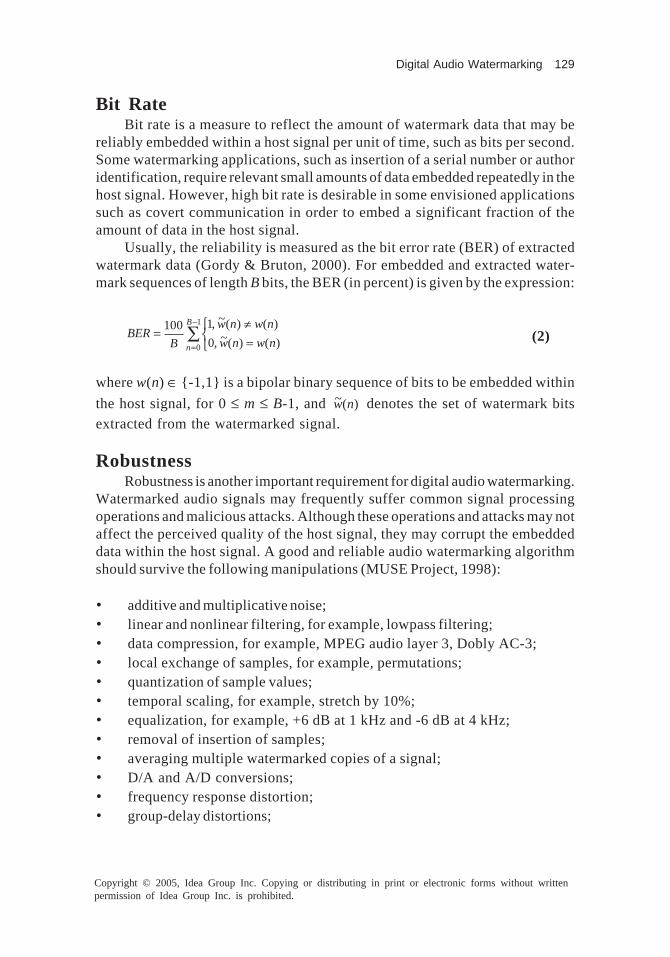
Digital Audio Watermarking 129
Copyright © 2005, Idea Group Inc. Copying or distributing in print or electronic forms without writtenpermission of Idea Group Inc. is prohibited.
Bit RateBit rate is a measure to reflect the amount of watermark data that may be
reliably embedded within a host signal per unit of time, such as bits per second.Some watermarking applications, such as insertion of a serial number or authoridentification, require relevant small amounts of data embedded repeatedly in thehost signal. However, high bit rate is desirable in some envisioned applicationssuch as covert communication in order to embed a significant fraction of theamount of data in the host signal.
Usually, the reliability is measured as the bit error rate (BER) of extractedwatermark data (Gordy & Bruton, 2000). For embedded and extracted water-mark sequences of length B bits, the BER (in percent) is given by the expression:
∑−
=
=≠
=1
0 )()(~,0
)()(~,1100 B
n nwnw
nwnw
BBER (2)
where w(n) ∈ {-1,1} is a bipolar binary sequence of bits to be embedded within
the host signal, for 0 ≤ m ≤ B-1, and )(~ nw denotes the set of watermark bitsextracted from the watermarked signal.
RobustnessRobustness is another important requirement for digital audio watermarking.
Watermarked audio signals may frequently suffer common signal processingoperations and malicious attacks. Although these operations and attacks may notaffect the perceived quality of the host signal, they may corrupt the embeddeddata within the host signal. A good and reliable audio watermarking algorithmshould survive the following manipulations (MUSE Project, 1998):
• additive and multiplicative noise;• linear and nonlinear filtering, for example, lowpass filtering;• data compression, for example, MPEG audio layer 3, Dobly AC-3;• local exchange of samples, for example, permutations;• quantization of sample values;• temporal scaling, for example, stretch by 10%;• equalization, for example, +6 dB at 1 kHz and -6 dB at 4 kHz;• removal of insertion of samples;• averaging multiple watermarked copies of a signal;• D/A and A/D conversions;• frequency response distortion;• group-delay distortions;

130 Xu & Tian
Copyright © 2005, Idea Group Inc. Copying or distributing in print or electronic forms without writtenpermission of Idea Group Inc. is prohibited.
• downmixing, for example, stereo to mono;• overdubbing, for example, placing another track into the audio.
Robustness can be measured by the bit error rate (BER) of the extractedwatermark data as a function of the amount of distortion introduced by a givenmanipulation.
SecurityIn order to prevent an unauthorized user from detecting the presence of
embedded data and remove the embedded data, the watermark embeddingprocedure must be secure in many applications. Different applications havedifferent security requirements. The most stringent requirements arise in covertcommunication scenarios. Security of data embedding procedures is interpretedin the same way as security of encryption techniques. A secure data embeddingprocedure cannot be broken unless the authorized user has access to a secret keythat controls the insertion of the data in the host signal. Hence, a data embeddingscheme is truly secure if knowing the exact algorithm for embedding the datadoes not help an unauthorized party detect the presence of embedded data. Anunauthorized user should not be able to extract the data in a reasonable amountof time even if he or she knows that the host signal contains data and is familiarwith the exact algorithm for embedding the data. Usually, the watermarkembedding method should open to the public, but the secret key is not released.In some applications, for example, covert communications, the data may also beencrypted prior to insertion in a host signal.
Computational ComplexityComputational complexity refers to the processing required to embed
watermark data into a host signal, and/or to extract the data from the signal. Itis essential and critical for the applications that require online watermarkembedding and extraction. Algorithm complexity is also important to influencethe choice of implementation structure or DSP architecture. Although there aremany ways to measure complexity, such as complexity analysis (or “Big-O”analysis) and actual CPU timings (in seconds), for practical applications morequantitative values are required (Cox et al., 1997).
HUMAN AUDITORY SYSTEMThe human auditory system (HAS) model has been successfully applied in
perceptual audio coding such as MPEG Audio Codec (Brandenburg & Stoll,1992). Similarly, HAS model can also be used in digital watermarking to embedthe data into the host audio signal more transparently and robustly.
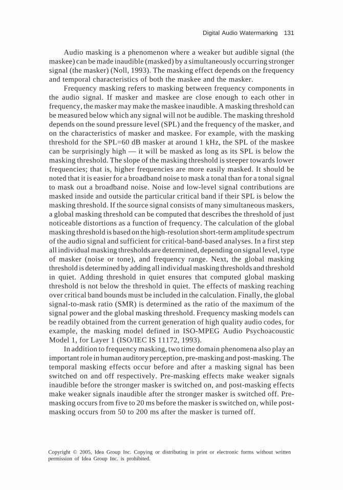
Digital Audio Watermarking 131
Copyright © 2005, Idea Group Inc. Copying or distributing in print or electronic forms without writtenpermission of Idea Group Inc. is prohibited.
Audio masking is a phenomenon where a weaker but audible signal (themaskee) can be made inaudible (masked) by a simultaneously occurring strongersignal (the masker) (Noll, 1993). The masking effect depends on the frequencyand temporal characteristics of both the maskee and the masker.
Frequency masking refers to masking between frequency components inthe audio signal. If masker and maskee are close enough to each other infrequency, the masker may make the maskee inaudible. A masking threshold canbe measured below which any signal will not be audible. The masking thresholddepends on the sound pressure level (SPL) and the frequency of the masker, andon the characteristics of masker and maskee. For example, with the maskingthreshold for the SPL=60 dB masker at around 1 kHz, the SPL of the maskeecan be surprisingly high — it will be masked as long as its SPL is below themasking threshold. The slope of the masking threshold is steeper towards lowerfrequencies; that is, higher frequencies are more easily masked. It should benoted that it is easier for a broadband noise to mask a tonal than for a tonal signalto mask out a broadband noise. Noise and low-level signal contributions aremasked inside and outside the particular critical band if their SPL is below themasking threshold. If the source signal consists of many simultaneous maskers,a global masking threshold can be computed that describes the threshold of justnoticeable distortions as a function of frequency. The calculation of the globalmasking threshold is based on the high-resolution short-term amplitude spectrumof the audio signal and sufficient for critical-band-based analyses. In a first stepall individual masking thresholds are determined, depending on signal level, typeof masker (noise or tone), and frequency range. Next, the global maskingthreshold is determined by adding all individual masking thresholds and thresholdin quiet. Adding threshold in quiet ensures that computed global maskingthreshold is not below the threshold in quiet. The effects of masking reachingover critical band bounds must be included in the calculation. Finally, the globalsignal-to-mask ratio (SMR) is determined as the ratio of the maximum of thesignal power and the global masking threshold. Frequency masking models canbe readily obtained from the current generation of high quality audio codes, forexample, the masking model defined in ISO-MPEG Audio PsychoacousticModel 1, for Layer 1 (ISO/IEC IS 11172, 1993).
In addition to frequency masking, two time domain phenomena also play animportant role in human auditory perception, pre-masking and post-masking. Thetemporal masking effects occur before and after a masking signal has beenswitched on and off respectively. Pre-masking effects make weaker signalsinaudible before the stronger masker is switched on, and post-masking effectsmake weaker signals inaudible after the stronger masker is switched off. Pre-masking occurs from five to 20 ms before the masker is switched on, while post-masking occurs from 50 to 200 ms after the masker is turned off.

132 Xu & Tian
Copyright © 2005, Idea Group Inc. Copying or distributing in print or electronic forms without writtenpermission of Idea Group Inc. is prohibited.
DIGITAL WATERMARKING FOR PCM AUDIODigital audio can be classified into three categories: PCM audio, WAV-
table synthesis audio and compressed audio. Most current audio watermarkingtechniques mainly focus on PCM audio. The popular methods include low-bitcoding, phase coding, spread spectrum coding, echo hiding, perceptual maskingand content-adaptive watermarking.
Low Bit CodingThe basic idea in low bit coding technique is to embed the watermark in an
audio signal by replacing the least significant bit of each sampling point by acoded binary string corresponding to the watermark. For example, in a 16-bitsper sample representation, the least four bits can be used for hiding. The retrievalof the hidden data in low-bit coding is done by reading out the value from the lowbits. The stego key is the position of altered bits. Low-bit coding is the simplestway to embed data into digital audio and can be applied in all ranges oftransmission rates with digital communication modes. Ideally, the channelcapacity will be 8kbps in an 8kHz sampled sequence and 44kbps in a 44kHzsampled sequence for a noiseless channel application. In return for this largechannel capacity, audio noise is introduced. The impact of this noise is a directfunction of the content of the original signal; for example, a live sports eventcontains crowd noise that makes the noise resultant from low-bit encoding.
The major disadvantage of the low bit coding method is its poor immunity tomanipulations. Encoded information can be destroyed by channel noise, re-sampling, and so forth, unless it is coded using redundancy techniques, whichreduces the data rate one to two orders of magnitude. In practice, it is useful onlyin closed, digital-to-digital environments.
Turner (1989) proposed a method for inserting an identification string intoa digital audio signal by substituting the “insignificant” bits of randomly selectedaudio samples with the bits of an identification code. Bits are deemed “insignifi-cant” if their alteration is inaudible. Unfortunately, Turner’s method may easilybe circumvented. For example, if it is known that the algorithm only affects theleast significant two bits of a word, then it is possible to randomly flip all such bits,thereby destroying any existing identification code. Bassia and Pitas (1998)proposed a watermarking scheme to embed a watermark in the time domain ofa digital audio signal by slightly modifying the amplitude of each audio sample.The characteristics of this modification are determined both by the original signaland the copyright owner. The detection procedure does not use the original audiosignal. But this method can only detect whether an audio signal contains awatermark or not. It cannot indicate the watermark information embedded in theaudio signal. Aris Technologies, Inc. (Wolosewicz & Jemeli, 1998) proposed atechnique to embed data by modifying signal peaks with their MusiCode product.Temporal peaks within a segment of host audio signal are modified to fall within

Digital Audio Watermarking 133
Copyright © 2005, Idea Group Inc. Copying or distributing in print or electronic forms without writtenpermission of Idea Group Inc. is prohibited.
quantized amplitude levels. The quantization pattern of the peaks is used todistinguish the embedded data. In Cooperman and Moskowitz (1997), Fouriertransform coefficients are computed on non-overlapping audio blocks. The leastsignificant bits of the transform coefficients are replaced by the embedded data.The DICE company offers a product based on this algorithm.
Phase CodingPhase coding is one of the most effective coding schemes in term of the
signal-to-noise ratio because experiments indicate that listeners might not hearany difference caused by a smooth phase shift, even though the signal patternmay change dramatically. When the phase relation between each frequencycomponents is dramatically changed, phase dispersion and “rain barrel” distor-tions occur. However, as long as the modification of the phase is within certainlimits an inaudible coding can be achieved.
In phase coding, a hidden datum is represented by a particular phase orphase change in the phase spectral. If the audio signal is divided into segments,data are usually hidden only in the first segment under two conditions. First, thephase difference between each segment needs to be preserved. The secondcondition states that the final phase spectral with embedded data needs to besmoothed; otherwise, an abrupt phase change causes hearing awareness. Oncethe embedding procedure is finished, the last step is to update the phase spectralof each of the remaining segments by adding back the relative phase. Conse-quently, the embedded signal can be constructed from this set of new phasespectral. For the extraction process, the hidden data can be obtained by detectingthe phase values from the phase spectral of the first segment. The stego key inthis implementation includes the phase shift and the size of one segment. Phasecoding can be used in both analog and digital modes but it is sensitive to mostaudio compressing algorithms.
The procedure for phase coding (Bender et al., 1996) is as follows:
1. Break the sound sequence s[i], (0 ≤ i ≤ I-1) into a series of N shortsegments, s
n[i] where (0 ≤ n ≤ N-1).
2. Apply a K-points discrete Fourier transform (DFT) to n-th segment, sn[i],
where (K = I/N), and create a matrix of the phase, φn(ω
k), and magnitude,
An(ω
k) for (0 ≤ k ≤ K-1).
3. Store the phase difference between each adjacent segment for (0 ≤ n ≤ N-1):
)()()( 11 knknkn ωφωφωφ −=∆ ++ (3)
4. A binary set of data is represented as a φdata
= π/2 or -π/2 representing0 or 1:

134 Xu & Tian
Copyright © 2005, Idea Group Inc. Copying or distributing in print or electronic forms without writtenpermission of Idea Group Inc. is prohibited.
''0 dataφφ = (4)
5. Re-create phase matrices for n>0 by using the phase difference:
∆+=
∆+=
∆+=
−
−
))()()((
...
))()()((
...
))()()((
'1
'
'1
'
1'0
'1
kNkNkN
knknkn
kkk
ωφωφωφ
ωφωφωφ
ωφωφωφ
(5)
6. Use the modified phase matrix φn'(ω
k) and the original magnitude matrix
An(ω
k) to reconstruct the sound signal by applying the inverse DFT.
For the decoding process, the synchronization of the sequence is donebefore the decoding. The length of the segment, the DFT points, and the datainterval must be known at the receiver. The value of the underlying phase of thefirst segment is detected as a 0 or 1, which represents the coded binary string.Since φ
0'(ω
k) is modified, the absolute phases of the following segments are
modified respectively. However, the relative phase difference of each adjacentframe is preserved. It is this relative difference in phase that the ear is mostsensitive to.
Phase coding is also applied to data hiding in speech signals (Yardimci et al.,1997).
Spread Spectrum CodingThe basic spread spectrum technique is designed to encrypt a stream of
information by spreading the encrypted data across as much of the frequencyspectrum as possible. It turns out that many spread spectrum techniques adaptwell to data hiding in audio signals. Because the hidden data are usually notexpected to be destroyed by operations such as compressing and cropping,broadband spread spectrum-based techniques, which make small modificationsto a large number of bits for each hidden datum, are expected to be robust againstthe operations. In a normal communication channel, it is often desirable toconcentrate the information in as narrow a region of the frequency spectrum aspossible. Among many different variations on the idea of spread spectrumcommunication, Direct Sequence (DS) is currently considered. In general,spreading is accomplished by modulating the original signal with a sequence ofrandom binary pulses (referred to as chip) with values 1 and -1. The chip rateis an integer multiple of the data rate. The bandwidth expansion is typically of theorder of 100 and higher.

Digital Audio Watermarking 135
Copyright © 2005, Idea Group Inc. Copying or distributing in print or electronic forms without writtenpermission of Idea Group Inc. is prohibited.
For the embedding process, the data to be embedded are coded as a binarystring using error-correction coding so that errors caused by channel noise andoriginal signal modification can be suppressed. Then, the code is multiplied by thecarrier wave and the pseudo-random noise sequence, which has a widefrequency spectrum. As a consequence, the frequency spectrum of the data isspread over the available frequency band. The spread data sequence is thenattenuated and added to the original signal as additive random noise. Forextraction, the same binary pseudo-random noise sequence applied for theembedding will be synchronously (in phase) multiplied with the embedded signal.
Unlike phase coding, DS introduces additive random noise to the audiosignal. To keep the noise level low and inaudible, the spread code is attenuated(without adaptation) to roughly 0.5% of the dynamic range of the original audiosignal. The combination of simple repetition technique and error correctioncoding ensure the integrity of the code. A short segment of the binary code stringis concatenated and added to the original signal so that transient noise can bereduced by averaging over the segment in the extraction process.
Most audio watermarking techniques are based on the spread spectrumscheme and are inherently projection techniques on a given key-defined direc-tion. In Tilki and Beex (1996), Fourier transform coefficients over the middlefrequency bands are replaced with spectral components from a signaturesequence. The middle frequency band is selected so that the data remain outsideof the more sensitive low frequency range. The signature is of short time durationand has a low amplitude relative to the local audio signal. The technique isdescribed as robust to noise and the wow and flutter of analogue tapes. InWolosewicz (1998), the high frequency portion of an audio segment is replacedwith embedded data. Ideally, the algorithm looks for segments in the audio withhigh energy. The significant low frequency energy helps to perceptually hide theembedded high frequency data. In addition, the segment should have low energyto ensure that significant components in the audio are not replaced with theembedded data. In a typical implementation, a block of approximately 675 bits ofdata is encoded using a spread spectrum algorithm with a 10kHz carrierwaveform. The duration of the resulting data block is 0.0675 seconds. The datablock is repeated in several locations according to the constraints imposed on theaudio spectrum. In another spread spectrum implementation, Pruess et al. (1994)proposed to embed data into the host audio signal as coloured noise. The data arecoloured by shaping a pseudo-noise sequence according to the shape of theoriginal signal. The data are embedded within a preselected band of the audiospectrum after proportionally shaping them by the corresponding audio signalfrequency components. Since the shaping helps to perceptually hide the embed-ded data, the inventors claim the composite audio signal is not readily distinguish-able from the original audio signal. The data may be recovered by essentiallyreversing the embedding operation using a whitening filter. Solana Technology

136 Xu & Tian
Copyright © 2005, Idea Group Inc. Copying or distributing in print or electronic forms without writtenpermission of Idea Group Inc. is prohibited.
Development Corp. (Lee et al., 1998) later introduced a similar approach withtheir Electronic DNA product. Time domain modelling, for example, linearpredictive coding, or fast Fourier transform is used to determine the spectralshape. Moses (1995) proposed a technique to embed data by encoding them asone or more whitened direct sequence spread spectrum signals and/or anarrowband FSK data signal and transmitted at the time, frequency and leveldetermined by a neural network such that the signal is masked by the audio signal.The neural network monitors the audio channel to determine opportunities toinsert the data such that the inserted data are masked.
Echo HidingEcho hiding (Gruhl et al., 1996) is a method for embedding information into
an audio signal. It seeks to do so in a robust fashion, while not perceivablydegrading the original signal. Echo hiding has applications in providing proof ofthe ownership, annotation, and assurance of content integrity. Therefore, theembedded data should not be sensitive to removal by common transform to theembedded audio, such as filtering, re-sampling, block editing, or lossy datacompression.
Echo hiding embeds data into a host audio signal by introducing an echo. Thedata are hidden by varying three parameters of the echo: initial amplitude, decayrate, and delay. As the delay between the original and the echo decreases, thetwo signals blend. At a certain point, the human ear cannot distinguish betweenthe two signals. The echo is perceived as added resonance. The coder uses twodelay times, one to represent a binary one and another to represent binary zero.Both delay times are below the threshold at which the human ear can resolve theecho. In addition to decreasing the delay time, the echo can also be ensuredunperceivable by setting the initial amplitude and the delay rate below the audiblethreshold of the human ear.
For the embedding process, the original audio signal (v(t)) is divided intosegments and one echo is embedded in each segment. In a simple case, theembedded signal (c(t)) can, for example, be expressed as follows:
c(t)=v(t)+av(t-d) (6)
where a is an amplitude factor. The stego key is the two echo delay times, of d and d'.The extraction is based on the autocorrelation of the cepstrum (i.e.,
logF(c(t))) of the embedded signal. The result in the time domain is F-
1(log(F(c(t))2). The decision of a d or a d' delay can be made by examining theposition of a spike that appears in the autocorrelation diagram. Echo hiding caneffectively place unperceivable information into an audio stream. It is robust tonoise and does not require a high data transmission channel. The drawback ofecho hiding is its unsafe stego key, so it is easy to be detected by attackers.

Digital Audio Watermarking 137
Copyright © 2005, Idea Group Inc. Copying or distributing in print or electronic forms without writtenpermission of Idea Group Inc. is prohibited.
Perceptual MaskingSwanson et al. (1998) proposed a robust audio watermarking approach
using perceptual masking. The major contributions of this method include:
• A perception-based watermarking procedure. The embedded water-mark adapts to each individual host signal. In particular, the temporal andfrequency distribution of the watermark are dictated by the temporal andfrequency masking characteristics of the host audio signal. As a result, theamplitude (strength) of the watermark increases and decreases with thehost signal, for example, lower amplitude in “quiet” regions of the audio.This guarantees that the embedded watermark is inaudible while having themaximum possible energy. Maximizing the energy of the watermark addsrobustness to attacks.
• An author representation that solves the deadlock problem. An authoris represented with a pseudo-random sequence created by a pseudo-random generator and two keys. One key is author-dependent, while thesecond key is signal-dependent. The representation is able to resolverightful ownership in the face of multiple ownership claims.
• A dual watermark. The watermarking scheme uses the original audiosignal to detect the presence of a watermark. The procedure can handlevirtually all types of distortions, including cropping, temporal rescaling, andso forth using a generalized likelihood ratio test. As a result, the watermarkingprocedure is a powerful digital copyright protection tool. This procedure isintegrated with a second watermark, which does not require the originalsignal. The dual watermarks also address the deadlock problem.
Each audio signal is watermarked with a unique noise-like sequence shapedby the masking phenomena. The watermark consists of (1) an author represen-tation, and (2) spectral and temporal shaping using the masking effects of thehuman auditory system. The watermarking scheme is based on a repeatedapplication of a basic watermarking operation on smaller segments of the audio
signal. The length N audio signal is first segmented into blocks )(ksi of length 512samples, i = 0, 1, ..., N/512 -1, and k = 0, 1, ..., 511. The block size of 512samples is dictated by the frequency masking model. For each audio segments
i(k), the algorithm works as follows.
1. compute the power spectrum Si(k) of the audio segment s
i(k);
2. compute the frequency mask Mi(k) of the power spectrum S
i(k);
3. use the mask Mi(k) to weight the noise-like author representation for that
audio block, creating the shaped author signature Pi(k) = Y
i(k)M
i(k);
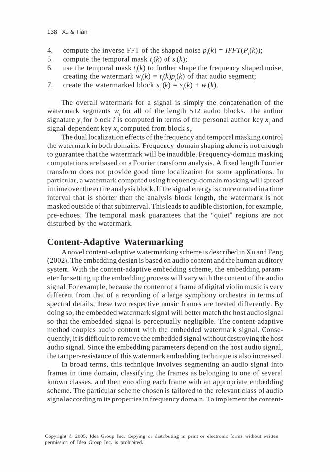
138 Xu & Tian
Copyright © 2005, Idea Group Inc. Copying or distributing in print or electronic forms without writtenpermission of Idea Group Inc. is prohibited.
4. compute the inverse FFT of the shaped noise pi(k) = IFFT(P
i(k));
5. compute the temporal mask ti(k) of s
i(k);
6. use the temporal mask ti(k) to further shape the frequency shaped noise,
creating the watermark wi(k) = t
i(k)p
i(k) of that audio segment;
7. create the watermarked block si'(k) = s
i(k) + w
i(k).
The overall watermark for a signal is simply the concatenation of thewatermark segments w
i for all of the length 512 audio blocks. The author
signature yi for block i is computed in terms of the personal author key x
1 and
signal-dependent key x2 computed from block s
i.
The dual localization effects of the frequency and temporal masking controlthe watermark in both domains. Frequency-domain shaping alone is not enoughto guarantee that the watermark will be inaudible. Frequency-domain maskingcomputations are based on a Fourier transform analysis. A fixed length Fouriertransform does not provide good time localization for some applications. Inparticular, a watermark computed using frequency-domain masking will spreadin time over the entire analysis block. If the signal energy is concentrated in a timeinterval that is shorter than the analysis block length, the watermark is notmasked outside of that subinterval. This leads to audible distortion, for example,pre-echoes. The temporal mask guarantees that the “quiet” regions are notdisturbed by the watermark.
Content-Adaptive WatermarkingA novel content-adaptive watermarking scheme is described in Xu and Feng
(2002). The embedding design is based on audio content and the human auditorysystem. With the content-adaptive embedding scheme, the embedding param-eter for setting up the embedding process will vary with the content of the audiosignal. For example, because the content of a frame of digital violin music is verydifferent from that of a recording of a large symphony orchestra in terms ofspectral details, these two respective music frames are treated differently. Bydoing so, the embedded watermark signal will better match the host audio signalso that the embedded signal is perceptually negligible. The content-adaptivemethod couples audio content with the embedded watermark signal. Conse-quently, it is difficult to remove the embedded signal without destroying the hostaudio signal. Since the embedding parameters depend on the host audio signal,the tamper-resistance of this watermark embedding technique is also increased.
In broad terms, this technique involves segmenting an audio signal intoframes in time domain, classifying the frames as belonging to one of severalknown classes, and then encoding each frame with an appropriate embeddingscheme. The particular scheme chosen is tailored to the relevant class of audiosignal according to its properties in frequency domain. To implement the content-

Digital Audio Watermarking 139
Copyright © 2005, Idea Group Inc. Copying or distributing in print or electronic forms without writtenpermission of Idea Group Inc. is prohibited.
adaptive embedding, two techniques are disclosed. They are audio frameclassification and embedding scheme design.
Figure 1 illustrates the watermark embedding scheme. The input originalsignal is divided into frames by audio segmentation. Feature measures areextracted from each frame to represent the characteristics of the audio signal ofthat frame. Based on the feature measures, the audio frame is classified into oneof the pre-defined classes and an embedding scheme is selected accordingly,which is tailored to the class. Using the selected embedding scheme, a water-mark is embedded into the audio frame using multiple-bit hopping and hidingmethod. In this scheme, the feature extraction method is exactly the same as theone used in the training processing. The parameters of the classifier and theembedding schemes are generated in the training process.
Figure 2 depicts the training process for an adaptive embedding model.Adaptive embedding, or content-sensitive embedding, embeds watermark dif-ferently for different types of audio signals. In order to do so, a training processis run for each category of audio signal to define embedding schemes that arewell suited to the particular category of audio signal. The training processanalyses an audio signal to find an optimal way to classify audio frames intoclasses and then design embedding schemes for each of those classes. Toachieve this objective, the training data should be sufficient to be statisticallysignificant. Audio signal frames are clustered into data clusters and each of themforms a partition in the feature vector space and has a centroid as its represen-tation. Since the audio frames in a cluster are similar, embedding schemes canbe designed according to the centroid of the cluster and the human audio systemmodel. The design of embedding schemes may need a lot of testing to ensure theinaudibility and robustness. Consequently, an embedding scheme is designed foreach class/cluster of signal that is best suited to the host signal. In the process,
Figure 1. Watermark embedding scheme for PCM audio
Original Audio Audio
Segmentation
Bit Embedding
Watermark Information
Watermarked
Audio
Classification & Embedding
Selection
Embedding Schemes
Bit Hopping
Classification Parameters
Feature Extraction

140 Xu & Tian
Copyright © 2005, Idea Group Inc. Copying or distributing in print or electronic forms without writtenpermission of Idea Group Inc. is prohibited.
inaudibility or the sensitivity of the human auditory system and resistance toattackers must be taken into considerations.
The training process needs to be performed only once for a category ofaudio signals. The derived classification parameters and the embedding schemesare used to embed watermarks in all audio signals in that category.
As shown in Figure 1 in the audio classification and embedding schemeselection, similar pre-processing will be conducted to convert the incoming audiosignal into feature frame sequences. Each frame is classified into one of thepredefined classes. An embedding scheme for a frame is chosen, which isreferred to as content-adaptive embedding scheme. In this way, the water-mark code is embedded frame by frame into the host audio signal.
Figure 3 illustrates the scheme of watermark extraction. The input signal isconverted into a sequence of frames by feature extraction. For the watermarkedaudio signal, it will be segmented into frames using the same segmentationmethod as in embedding process. Then the bit detection is conducted to extractbit delays on a frame-by-frame basis. Because a single bit of the watermark ishopped into multiple bits through bit hopping in the embedding process, multipledelays are detected in each frame. This method is more robust against attackerscompared with the single bit hiding technique. Firstly, one frame is encoded withmultiple bits, and any attackers do not know the coding parameters. Secondly,the embedded signal is weaker and well hidden as a consequence of usingmultiple bits.
The key step of the bit detection involves the detection of the spacingbetween the bits. To do this, the magnitude (at relevant locations in each audioframe) of an autocorrelation of an embedded signal’s cepstrum (Gruhl et al.,1996) is examined. Cepstral analysis utilises a form of a homomorphic systemthat coverts the convolution operation into an addition operation. It is useful indetecting the existence of embedded bits. From the autocorrelation of thecepstrum, the embedded bits in each audio frame can be found according to a“power spike” at each delay of the bits.
Figure 2. Training and embedding scheme design
Training Data
Audio
Segmentation
Feature Extraction
Feature Clustering
Embedding Design
HAS
Classification Parameters
Embedding Schemes
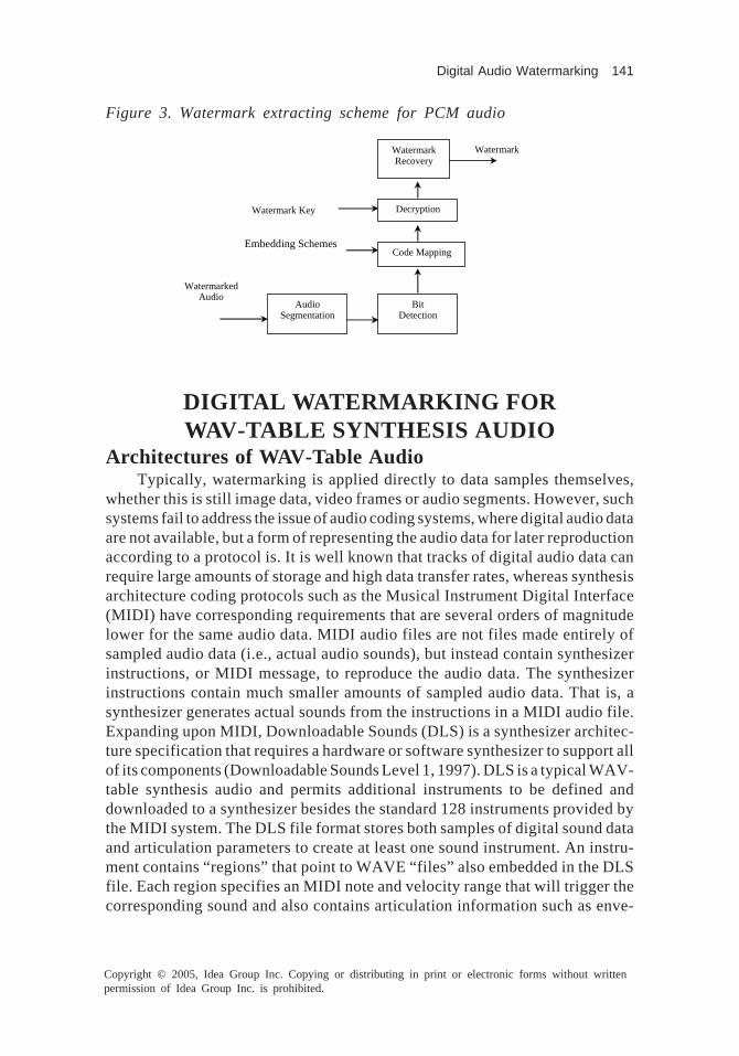
Digital Audio Watermarking 141
Copyright © 2005, Idea Group Inc. Copying or distributing in print or electronic forms without writtenpermission of Idea Group Inc. is prohibited.
DIGITAL WATERMARKING FORWAV-TABLE SYNTHESIS AUDIO
Architectures of WAV-Table AudioTypically, watermarking is applied directly to data samples themselves,
whether this is still image data, video frames or audio segments. However, suchsystems fail to address the issue of audio coding systems, where digital audio dataare not available, but a form of representing the audio data for later reproductionaccording to a protocol is. It is well known that tracks of digital audio data canrequire large amounts of storage and high data transfer rates, whereas synthesisarchitecture coding protocols such as the Musical Instrument Digital Interface(MIDI) have corresponding requirements that are several orders of magnitudelower for the same audio data. MIDI audio files are not files made entirely ofsampled audio data (i.e., actual audio sounds), but instead contain synthesizerinstructions, or MIDI message, to reproduce the audio data. The synthesizerinstructions contain much smaller amounts of sampled audio data. That is, asynthesizer generates actual sounds from the instructions in a MIDI audio file.Expanding upon MIDI, Downloadable Sounds (DLS) is a synthesizer architec-ture specification that requires a hardware or software synthesizer to support allof its components (Downloadable Sounds Level 1, 1997). DLS is a typical WAV-table synthesis audio and permits additional instruments to be defined anddownloaded to a synthesizer besides the standard 128 instruments provided bythe MIDI system. The DLS file format stores both samples of digital sound dataand articulation parameters to create at least one sound instrument. An instru-ment contains “regions” that point to WAVE “files” also embedded in the DLSfile. Each region specifies an MIDI note and velocity range that will trigger thecorresponding sound and also contains articulation information such as enve-
Figure 3. Watermark extracting scheme for PCM audio
Watermarked Audio
Code Mapping
Bit Detection
Audio Segmentation
Watermark Recovery
Watermark
Decryption Watermark Key
Embedding Schemes
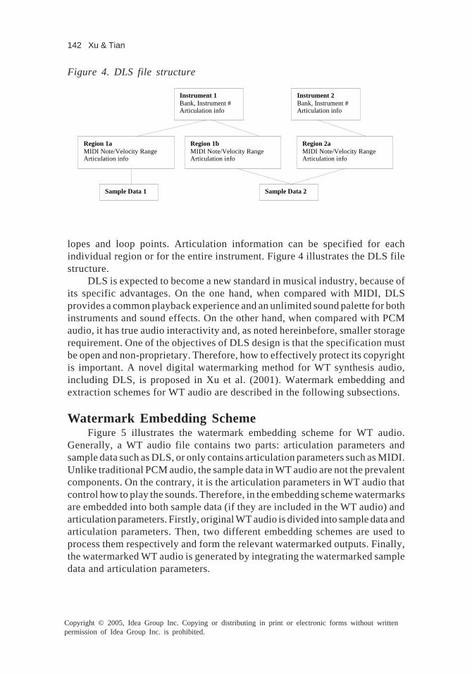
142 Xu & Tian
Copyright © 2005, Idea Group Inc. Copying or distributing in print or electronic forms without writtenpermission of Idea Group Inc. is prohibited.
lopes and loop points. Articulation information can be specified for eachindividual region or for the entire instrument. Figure 4 illustrates the DLS filestructure.
DLS is expected to become a new standard in musical industry, because ofits specific advantages. On the one hand, when compared with MIDI, DLSprovides a common playback experience and an unlimited sound palette for bothinstruments and sound effects. On the other hand, when compared with PCMaudio, it has true audio interactivity and, as noted hereinbefore, smaller storagerequirement. One of the objectives of DLS design is that the specification mustbe open and non-proprietary. Therefore, how to effectively protect its copyrightis important. A novel digital watermarking method for WT synthesis audio,including DLS, is proposed in Xu et al. (2001). Watermark embedding andextraction schemes for WT audio are described in the following subsections.
Watermark Embedding SchemeFigure 5 illustrates the watermark embedding scheme for WT audio.
Generally, a WT audio file contains two parts: articulation parameters andsample data such as DLS, or only contains articulation parameters such as MIDI.Unlike traditional PCM audio, the sample data in WT audio are not the prevalentcomponents. On the contrary, it is the articulation parameters in WT audio thatcontrol how to play the sounds. Therefore, in the embedding scheme watermarksare embedded into both sample data (if they are included in the WT audio) andarticulation parameters. Firstly, original WT audio is divided into sample data andarticulation parameters. Then, two different embedding schemes are used toprocess them respectively and form the relevant watermarked outputs. Finally,the watermarked WT audio is generated by integrating the watermarked sampledata and articulation parameters.
Figure 4. DLS file structure
Instrument 1 Bank, Instrument # Articulation info
Instrument 2 Bank, Instrument # Articulation info
Region 1a MIDI Note/Velocity Range Articulation info
Region 1b MIDI Note/Velocity Range Articulation info
Region 2a MIDI Note/Velocity Range Articulation info
Sample Data 1 Sample Data 2

Digital Audio Watermarking 143
Copyright © 2005, Idea Group Inc. Copying or distributing in print or electronic forms without writtenpermission of Idea Group Inc. is prohibited.
Adaptive Coding Based on Finite AutomatonFigure 6 shows the scheme of adaptive coding. In this scheme, techniques
(finite automaton and redundancy) are proposed to improve the robustness. Inaddition, the bits of sample data are adaptively coded according to HAS so as toguarantee the minimum distortion of original sample data. The watermarkmessage is firstly converted into a string of binary sequence. Each bit of thesequence will replace a corresponding bit of the sample points. The particularlocation in sample points is determined by finite automaton and HAS. Thenumber of sample points is calculated according to the redundancy technique.
Adaptive bit coding has, however, low immunity to manipulations. Embed-ded information can be destroyed by channel noise, re-sampling, and otheroperations. Adaptive bit coding technique is used based on several consider-ations. Firstly, unlike sampled digital audio, WT audio is a parameterised digitalaudio, so it is difficult to attack it using the typical signal processing techniquessuch as adding noise and re-sampling. Secondly, the size of wave sample in WTaudio is very small, and therefore it is unsuitable to embed a watermark into thesamples in the frequency domain. Finally, in order to ensure robustness, thewatermarked bit sequence of sample data is embedded into the articulationparameters of WT audio. If the sample data are distorted, the embeddedinformation can be used to restore the watermarked bit of the sample data.
The functionality of a finite automaton M can be described as a quintuple:
>=< λδ ,,,, SYXM (7)
where X is a non-empty finite set (the input alphabet of M), Y is a non-empty finiteset (the output alphabet of M), S is a non-empty finite set (the state alphabet ofM), δ : S × X → S is a single-valued mapping (the next state function of M) andλ : S × X → Y is a single-valued mapping (the output function of M).
Figure 5. Watermark embedding scheme for WAV-table synthesis audio
Original WT
Content Extraction
Articulation Parameters
Sample Data
Parameters Hiding
Adaptive Coding
Watermark
Watermarked Sample Data
Watermarked Articulation Parameters
Coding-Bit Extraction
Integration
Watermarked WT

144 Xu & Tian
Copyright © 2005, Idea Group Inc. Copying or distributing in print or electronic forms without writtenpermission of Idea Group Inc. is prohibited.
The elements λδ ,,,, SYX are expressed as follows:
}1,0{=X (8)
},,,{ 4321 yyyyY = (9)
},,,,{ 43210 SSSSSS = (10)
),(1 xSS ii δ=+ (11)
),( xSy ii λ= (12)
where yi (i=1,2,3,4) is the number of sample points that are jumped off when
embedding bit corresponding to relevant states, and Si (i = 0 - 4) is five kinds of
states corresponding to 0, 00, 01, 10 and 11 respectively, and S0 is to be supposed
the initial state. The state transfer diagram of finite automaton is shown in Figure 7.An example procedure of redundancy low-bit coding method based on FA andHAS is described as follows:
1. Convert the watermark message into binary sequence;2. Determine the values of the elements in FA; that is, the number of sample
points that will be jumped off corresponding relevant states:y
1: state 00
y2: state 01
y3: state 10
y4: state 11
3. Determine the redundant number for 0 and 1 bit to be embedded:r
0: the embedded number for 0 bit;
r1: the embedded number for 1 bit;
Figure 6. Adaptive-bit coding scheme
Sample Frame
Binary Sequence (Watermark)
Sample Location
FA
Redundancy Adaptive Coding
Watermarked Sample Frame
HAS

Digital Audio Watermarking 145
Copyright © 2005, Idea Group Inc. Copying or distributing in print or electronic forms without writtenpermission of Idea Group Inc. is prohibited.
4. Determine the HAS threshold T;5. For each bit of the binary sequence corresponding to watermark message
and the sample point in the WT sample data,(a) Compare the amplitude value A of sample point with HAS threshold
T; if A<T then go to next point, else(b) Step over y
i(i = 1,2,3,4) number of points and replace the lowest bit of
rj(j = 0,1) number of points by the bit of the binary sequence;
(c) Repeat until all bits in binary sequence are processed.
Parameters HidingIn order to improve the robustness of watermarked WT audio, the water-
mark (and watermarked bit sequence if necessary) is also embedded intoarticulation parameters. This process is shown in Figure 8. Watermark andwatermarked bit sequence are encrypted and form a data stream. In themeantime, some virtual parameters are generated to be used to embed thewatermark data stream into the WT articulation parameters. Because thelocation of the parameters is not known to attackers, the embedded data aredifficult to be detected and removed in the presence of attacks. On the otherhand, it can ensure the correction of detection if the watermarks in WT sampledata are distorted when both watermark and watermarked bit sequence areembedded into the articulation parameters.
The basic idea of the parameters hiding scheme is to embed the watermarkinformation into the articulation parameters of WT audio by generating somevirtual parameters. The Downloadable Sounds (DLS) Level 1 is used as anexample to illustrate how to hide watermark information in articulation param-eters.
1. Encrypt the watermark binary sequence and watermarked low-bits se-quence;
Figure 7. Finite automaton
1S
0S
0S
2S
3S 4S
01 00
01 10 11 00
10 11
0100

146 Xu & Tian
Copyright © 2005, Idea Group Inc. Copying or distributing in print or electronic forms without writtenpermission of Idea Group Inc. is prohibited.
2. Segment the encrypted data stream into n parts;3. Create a virtual instrument in DLS file, and use its parameters to hide the
watermark information.
The virtual instrument collection to hide watermark information can bedescribed as follows:
LIST ‘ins’ LIST ‘INFO’ Inam “Instrument name” <dlid> (watermark Info part 1) <insh> (watermark Info part 2) LIST ‘lrgn’ LIST ‘rgn’ <rgnh> (watermark Info part 3) <wsmp> (watermark Info part 4) <wlnk> (watermark Info part 5) LIST ‘rgn’ . . . … LIST ‘lart’ <art1> (watermark Info part n )
Watermark Extraction SchemeFigure 9 shows the scheme of watermark extraction. In the extraction
process, the original WT audio is not needed. For a watermarked WT audio, itis also divided into sample data and articulation parameters at first. Then the
Figure 8. Parameters hiding scheme
Watermarked Bit Sequence
Watermark
Encryption
WT Articulation Parameters
Generate Virtual
Parameters
Embedding Watermark
into Parameters
Watermarked Articulation Parameters

Digital Audio Watermarking 147
Copyright © 2005, Idea Group Inc. Copying or distributing in print or electronic forms without writtenpermission of Idea Group Inc. is prohibited.
watermark sequence in the coding bits of the sample data and the encryptedwatermark information in the articulation parameters are detected. If thewatermark sequence in sample data is obtained, it will be compared with thewatermark in articulation parameters to make the verification. If the sample datasuffered from distortions and the watermark sequence cannot be detected, thewatermarked bit sequence in the articulation parameters will be used to restorethe watermarked bit information in the sample data and make the detection in therestored data. Similarly, the detected watermark will be verified by comparingwith that embedded in articulation parameters.
DIGITAL WATERMARKINGFOR COMPRESSED AUDIO
Compression algorithms for digital audio can preserve audio quality as wellas reduce bit rate dramatically, increase network bandwidth, and save densitystorage of audio content. Among various kinds of compressed digital audiocurrently used, MP3 is the most popular one and gets more and more welcomedby music users. MP3 audio compression is based on psycho-acoustic models ofthe human auditory system. It is an ideal format for distributing high-qualitysound files online because it can offer near-CD quality at the compression ratioof 11 to one (128kb/s).
Compressed Domain WatermarkingOne possible method to protect compressed audio is to decompress it first,
then embed a watermark into decompressed audio, and finally recompress thewatermarked decompressed audio. This can probably ensure the robustness ofthe watermark, but it is too time consuming because the compression process willtake a long time. For example, it will take more than 30 minutes to compress a
Figure 9. Watermark extraction scheme for WAV-table synthesis audio
Watermarked WT
Content Extraction
Sample Data
Articulation Parameters
Coding Bit Detection
Embedded Information Detection
Verification Watermark
Watermark Information
Watermarked Bit Information
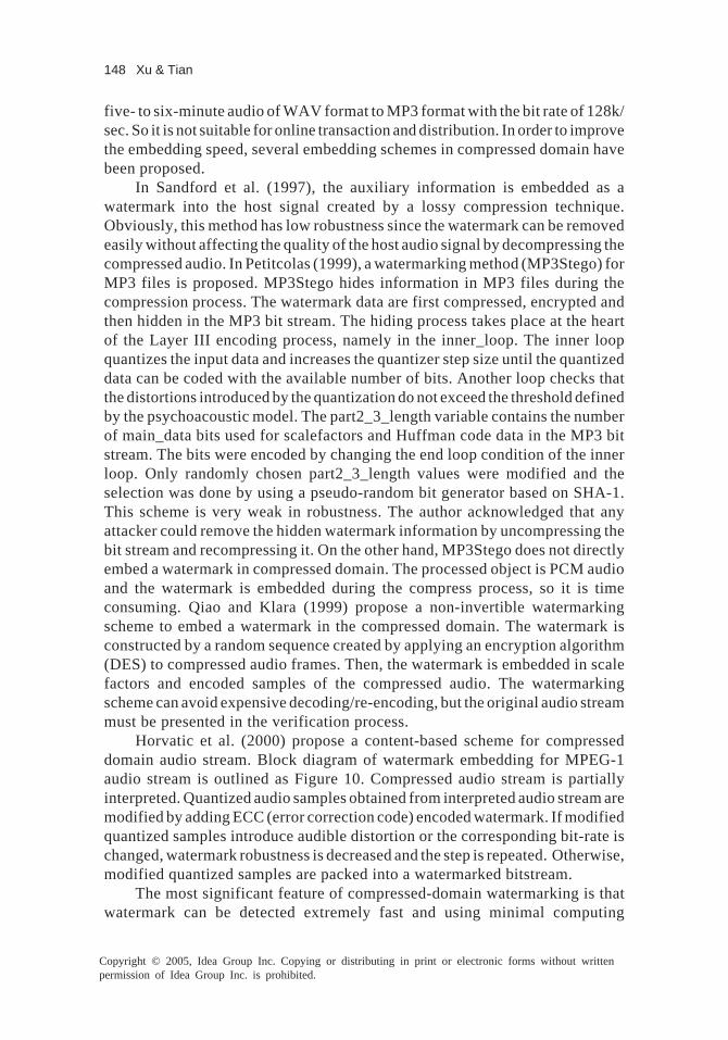
148 Xu & Tian
Copyright © 2005, Idea Group Inc. Copying or distributing in print or electronic forms without writtenpermission of Idea Group Inc. is prohibited.
five- to six-minute audio of WAV format to MP3 format with the bit rate of 128k/sec. So it is not suitable for online transaction and distribution. In order to improvethe embedding speed, several embedding schemes in compressed domain havebeen proposed.
In Sandford et al. (1997), the auxiliary information is embedded as awatermark into the host signal created by a lossy compression technique.Obviously, this method has low robustness since the watermark can be removedeasily without affecting the quality of the host audio signal by decompressing thecompressed audio. In Petitcolas (1999), a watermarking method (MP3Stego) forMP3 files is proposed. MP3Stego hides information in MP3 files during thecompression process. The watermark data are first compressed, encrypted andthen hidden in the MP3 bit stream. The hiding process takes place at the heartof the Layer III encoding process, namely in the inner_loop. The inner loopquantizes the input data and increases the quantizer step size until the quantizeddata can be coded with the available number of bits. Another loop checks thatthe distortions introduced by the quantization do not exceed the threshold definedby the psychoacoustic model. The part2_3_length variable contains the numberof main_data bits used for scalefactors and Huffman code data in the MP3 bitstream. The bits were encoded by changing the end loop condition of the innerloop. Only randomly chosen part2_3_length values were modified and theselection was done by using a pseudo-random bit generator based on SHA-1.This scheme is very weak in robustness. The author acknowledged that anyattacker could remove the hidden watermark information by uncompressing thebit stream and recompressing it. On the other hand, MP3Stego does not directlyembed a watermark in compressed domain. The processed object is PCM audioand the watermark is embedded during the compress process, so it is timeconsuming. Qiao and Klara (1999) propose a non-invertible watermarkingscheme to embed a watermark in the compressed domain. The watermark isconstructed by a random sequence created by applying an encryption algorithm(DES) to compressed audio frames. Then, the watermark is embedded in scalefactors and encoded samples of the compressed audio. The watermarkingscheme can avoid expensive decoding/re-encoding, but the original audio streammust be presented in the verification process.
Horvatic et al. (2000) propose a content-based scheme for compresseddomain audio stream. Block diagram of watermark embedding for MPEG-1audio stream is outlined as Figure 10. Compressed audio stream is partiallyinterpreted. Quantized audio samples obtained from interpreted audio stream aremodified by adding ECC (error correction code) encoded watermark. If modifiedquantized samples introduce audible distortion or the corresponding bit-rate ischanged, watermark robustness is decreased and the step is repeated. Otherwise,modified quantized samples are packed into a watermarked bitstream.
The most significant feature of compressed-domain watermarking is thatwatermark can be detected extremely fast and using minimal computing

Digital Audio Watermarking 149
Copyright © 2005, Idea Group Inc. Copying or distributing in print or electronic forms without writtenpermission of Idea Group Inc. is prohibited.
resources. Watermark detection becomes part of the MPEG-1 decoding processand does not interfere with audio playback while adding little additionalprocessing. Block diagram of watermark detection for MPEG-1 audio streamintegrated within the ISO MPEG-1 Audio Decoder is outlined as Figure 11.
This compressed domain watermarking method has minimal resourceconsumption and ability to integrate a watermarking module directly into real-time IP streaming applications including live broadcasting, video/audio ondemand, secure IP telephony, high quality video conferencing, and others. Basedon desired bitrate and perceptual quality, watermark robustness is adaptiveand watermark energy automatically adapts to the bitrate and audio distortionlimits. It is able to sustain significant packet loss. Successive watermarks areinterlaced with marks used for watermark synchronisation when audio stream isexposed to packet loss or bit-rate conversion. This method also uses key-basedrandom sequences to modulate watermark information prior to embedding toenable existence of multiple watermarks simultaneously.
Figure10. Compressed-domain watermarking
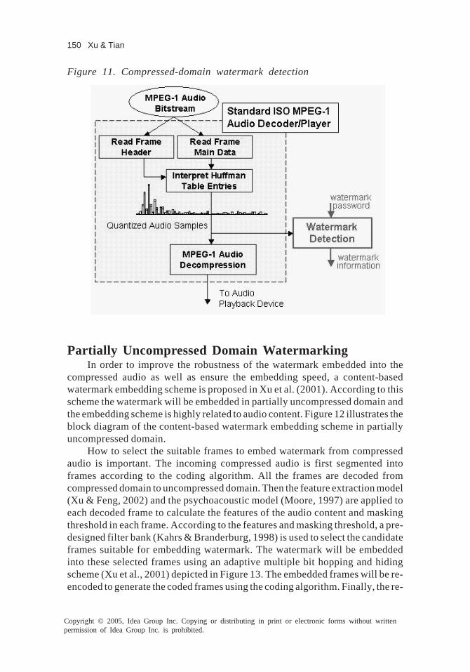
150 Xu & Tian
Copyright © 2005, Idea Group Inc. Copying or distributing in print or electronic forms without writtenpermission of Idea Group Inc. is prohibited.
Partially Uncompressed Domain WatermarkingIn order to improve the robustness of the watermark embedded into the
compressed audio as well as ensure the embedding speed, a content-basedwatermark embedding scheme is proposed in Xu et al. (2001). According to thisscheme the watermark will be embedded in partially uncompressed domain andthe embedding scheme is highly related to audio content. Figure 12 illustrates theblock diagram of the content-based watermark embedding scheme in partiallyuncompressed domain.
How to select the suitable frames to embed watermark from compressedaudio is important. The incoming compressed audio is first segmented intoframes according to the coding algorithm. All the frames are decoded fromcompressed domain to uncompressed domain. Then the feature extraction model(Xu & Feng, 2002) and the psychoacoustic model (Moore, 1997) are applied toeach decoded frame to calculate the features of the audio content and maskingthreshold in each frame. According to the features and masking threshold, a pre-designed filter bank (Kahrs & Branderburg, 1998) is used to select the candidateframes suitable for embedding watermark. The watermark will be embeddedinto these selected frames using an adaptive multiple bit hopping and hidingscheme (Xu et al., 2001) depicted in Figure 13. The embedded frames will be re-encoded to generate the coded frames using the coding algorithm. Finally, the re-
Figure 11. Compressed-domain watermark detection

Digital Audio Watermarking 151
Copyright © 2005, Idea Group Inc. Copying or distributing in print or electronic forms without writtenpermission of Idea Group Inc. is prohibited.
encoded frames and the non-embedded frames will be reconstructed to generatethe watermarked compressed audio. Compared with embedding schemes inwholly uncompressed domain, this scheme can not only get the same perfor-mance in audibility and robustness but also embed the watermark much faster.It is suitable for online embedding and distribution. Compared with the embed-ding schemes in compressed domain, this scheme has high robustness forembedded watermark.
Figure 13 illustrates the block diagram of detailed watermark embeddingscheme for decoded frames from the compressed audio. Since audio coding isa lossy processing, the embedded watermark must exist after audio compres-sion. Furthermore, the embedded watermark must not affect the audio qualityperceptually. In order to satisfy these requirements, the embedding scheme fullyconsiders the human auditory system and the features of audio content. For thedecoded frames from the original compressed audio that will be selected toembed watermark, feature parameters (Xu & Feng, 2002) are extracted fromeach selected frame to represent the characteristics of the audio content in thatframe. In the meantime, each selected frame will pass through a psycho-acousticmodel (Moore, 1997) to determine the ratio of the signal energy to the maskingthreshold. Based on the feature parameters and masking threshold, the embed-ding scheme for each selected frame is designed. The watermark is embeddedinto these frames using a multiple-bit hopping and hiding method (Xu et al., 2001).The watermarked audio frame will be compressed to generate the compressedaudio frame.
In order to correctly detect the watermark from a compressed audio, theframes embedded watermark must be extracted at first. Figure 14 illustrates howto extract the frames including watermark from a compressed audio. This
Figure 12. Content-based watermark embedding scheme for compressedaudio
Compressed Audio
Feature Extraction
Psychoacoustic Model
Frame 1
Frame 2
Frame n
Filter Bank
Watermark
Watermarked Compressed Audio
Selected Frames
(Decoded)
Decode
Frame Segmentation Decode
• • •
Embedded Frames
(Decoded) Embedding
Scheme
Embedded Frames (Coded)
Re-Encode Frame Reconstruction
Non-embedded Frames (Coded)
Decode
• • •
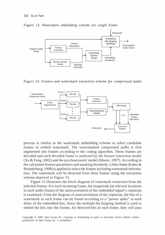
152 Xu & Tian
Copyright © 2005, Idea Group Inc. Copying or distributing in print or electronic forms without writtenpermission of Idea Group Inc. is prohibited.
process is similar to the watermark embedding scheme to select candidateframes to embed watermark. The watermarked compressed audio is firstsegmented into frames according to the coding algorithm. These frames aredecoded and each decoded frame is analyzed by the feature extraction model(Xu & Feng, 2002) and the psychoacoustic model (Moore, 1997). According tothe calculated feature parameters and masking threshold, a filter bank (Kahrs &Branderburg, 1998) is applied to select the frames including watermark informa-tion. The watermark will be detected from these frames using the extractionscheme depicted as Figure 15.
Figure 15 illustrates the block diagram of watermark extraction from theselected frames. For each incoming frame, the magnitude (at relevant locationsin each audio frame) of the autocorrelation of the embedded signal’s cepstrumis examined. From the diagram of autocorrelation of the cepstrum, the bits of awatermark in each frame can be found according to a “power spike” at eachdelay of the embedded bits. Since the multiple-bit hopping method is used toembed the bits into the frames, for detected bits in each frame, they will pass
Figure 13. Watermark embedding scheme for single frame
Figure 14. Frames and watermark extraction scheme for compressed audio
Original Audio Frame
Feature Parameters
Masking Threshold
Embedding Parameters
Watermark
Watermarked Audio Frame Feature
Extraction
Psycho-acoustic Model
Embedding Scheme Design
Embedding (Bit Hopping
&Hiding)
Feature Extraction
Psychoacoustic Model
Frame 2
Frame n
Filter Bank
Watermark
Watermarked Compressed Audio
• • •
• • • Embedded Frames
(Decoded)
Frame Segmentation
Decode
Decode
Decode
Extraction Scheme
Frame 1
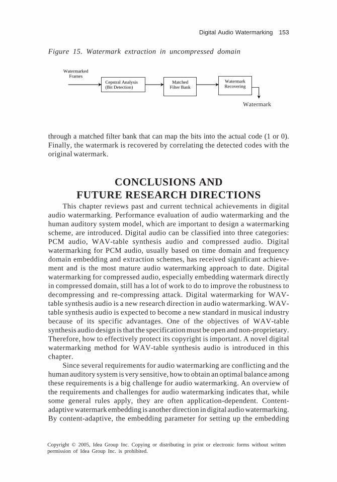
Digital Audio Watermarking 153
Copyright © 2005, Idea Group Inc. Copying or distributing in print or electronic forms without writtenpermission of Idea Group Inc. is prohibited.
through a matched filter bank that can map the bits into the actual code (1 or 0).Finally, the watermark is recovered by correlating the detected codes with theoriginal watermark.
CONCLUSIONS ANDFUTURE RESEARCH DIRECTIONS
This chapter reviews past and current technical achievements in digitalaudio watermarking. Performance evaluation of audio watermarking and thehuman auditory system model, which are important to design a watermarkingscheme, are introduced. Digital audio can be classified into three categories:PCM audio, WAV-table synthesis audio and compressed audio. Digitalwatermarking for PCM audio, usually based on time domain and frequencydomain embedding and extraction schemes, has received significant achieve-ment and is the most mature audio watermarking approach to date. Digitalwatermarking for compressed audio, especially embedding watermark directlyin compressed domain, still has a lot of work to do to improve the robustness todecompressing and re-compressing attack. Digital watermarking for WAV-table synthesis audio is a new research direction in audio watermarking. WAV-table synthesis audio is expected to become a new standard in musical industrybecause of its specific advantages. One of the objectives of WAV-tablesynthesis audio design is that the specification must be open and non-proprietary.Therefore, how to effectively protect its copyright is important. A novel digitalwatermarking method for WAV-table synthesis audio is introduced in thischapter.
Since several requirements for audio watermarking are conflicting and thehuman auditory system is very sensitive, how to obtain an optimal balance amongthese requirements is a big challenge for audio watermarking. An overview ofthe requirements and challenges for audio watermarking indicates that, whilesome general rules apply, they are often application-dependent. Content-adaptive watermark embedding is another direction in digital audio watermarking.By content-adaptive, the embedding parameter for setting up the embedding
Figure 15. Watermark extraction in uncompressed domain
Watermarked
Frames Cepstral Analysis (Bit Detection)
Matched Filter Bank
Watermark Recovering
WatermarWatermark

154 Xu & Tian
Copyright © 2005, Idea Group Inc. Copying or distributing in print or electronic forms without writtenpermission of Idea Group Inc. is prohibited.
process will vary with the content of the audio signal. By doing so, the embeddedwatermark signal will better match the host audio signal so that the embeddedsignal is perceptually negligible. The content-adaptive method couples audiocontent with embedded watermark signal. Consequently, it is difficult to removethe embedded signal without destroying the host audio signal.
REFERENCESBassia, P., & Pitas, I. (1998). Robust audio watermarking in the time domain. IX
European Signal Processing Conference (EUSIPCO’98), September 8-11, 1, 13-16, Rhodes, Greece.
Beerends, J., & Stemerdink, J. (1992). A perceptual audio quality measurementbased on a psychoacoustic sound representation. Journal of AES, 40(12),963-972.
Bender, W., Gruhl, D., Morimoto, N., & Lu, A. (1996). Techniques for datahiding. IBM Systems Journal, 35(3/4), 313-336.
Brandenburg, K., & Stoll, G. 1992). The ISO/MPEG-Audio Codec: A genericstandard for coding of high quality digital audio. The 92nd AESConvention, Wien, Marz.
Cooperman, M., & Moskowitz, M. (1997). Steganographic method and device,US Patent 5,613,004.
Cox, I.J., Kilian, J., Leighton, T., & Shamoon, T. (1995). Secure spreadspectrum watermarking for multimedia. Technical Report 95-10, NECResearch Institute.
Cox, I.J., Kilian, J., Leighton, T., & Shamoon, T. (1997). Secure spread spectrumwatermarking for multimedia. IEEE Transactions on Image Processing,6(12), 1673-1687.
Delaigle, J.F., Vleeschouver, C., & Macq, B. (1996). Digital watermarking.Proceedings of SPIE, Optical Security and Counterfeit DeterrenceTechniques, 2659, (pp. 99-110).
Downloadable Sounds Level 1, Version 1.0. (1997). The MIDI ManufacturersAssociation, CA, USA.
Gordy, J.D., & Bruton, L.T. (2000). Performance evaluation of digital audiowatermarking algorithms. Proceedings of IEEE MWSCAS 2000.
Gruhl, D., Lu, A., & Bender, W. (1996). Echo hiding. Proceedings of Informa-tion Hiding Workshop, (pp. 295-315). University of Cambridge.
Horvatic, P., Zhao, J., & Thorwirth, N.J. (2000). Robust audio watermarkingbased on secure spread spectrum and auditory perception model. In S. Qing(Ed.), International Federation for Information Processing (IFIP):Information security for global information infrastructures (pp. 181-190). Boston, MA: Kluwer Academic Publishers.

Digital Audio Watermarking 155
Copyright © 2005, Idea Group Inc. Copying or distributing in print or electronic forms without writtenpermission of Idea Group Inc. is prohibited.
ISO/IEC IS 11172. (1993). Information technology – Coding of movingpictures and associated audio for digital storage up to about 1.5Mbits/s.
Kahrs, M., & Branderburg, K. (1998). Applications of digital signal process-ing to audio and acoustics. Kluwer Academic Publishers.
Lee, C., Moallemi, K., & Warren, R. (1998). Method and apparatus fortransporting auxiliary data in audio signals, US Patent 5,822,360.
Moore, B.J.C. (1997). An introduction to the psychology of hearing (4th ed.).Academic Press.
Moses, D. (1995). Simultaneous transmission data and audio signals bymeans of perceptual coding, US Patent 5,473,631.
MUSE Project: Embedded signalling. Available online: www.ifpi.org/technol-ogy/muse_embed.html.
Noll, P. (1993). Wideband speech and audio coding. IEEE CommunicationsMagazine, 31(11), 34-44.
Petitcolas, F. Available online: http://www.cl.cam.ac.uk/~fapp2/steganography/mp3stego/ Cambridge University, UK.
Pitas, I. (1996). A method for signature casting on digital images. Proceedingsof IEEE International Conference on Image Processing, (vol. 3, pp.215-218).
Preuss, R., Roukos, S., Huggins, A., Gish, H., Bergamo, M., & Peterson, P.(1994). Embedded signalling, US patent 5,319,735.
Qiao, L., & Klara, N. (1999, January). Non-invertible watermarking scheme forMPEG audio, Proceedings of SPIE Multimedia Security Conference,San Jose, CA.
Sandford, S. (1997). Compression embedding, US Patent 5,778,102.Swanson, M.D., Zhu, B., & Tewfik, A.H. (1996). Transparent robust image
watermarking. Proc. IEEE Int. Conf. on Image Processing, 3, 211-214.Swanson, M.D., Zhu, B., Tewfik, A.H., & Boney, L. (1998). Robust audio
watermarking using perceptual masking. Signal Processing, 66, 337-355.Tilki, J.F., & Beex, A.A. (1996). Encoding a hidden digital signature onto an
audio signal using psychoacoustic masking. Proc. of 7th Int. Conf. on Sig.Proc. Apps. and Tech., (pp. 476-480).
Turner, L.F. (1989). Digital data security system, Patent IPN WO 89/08915.Wolfgang, R.B., & Delp, E.J. (1996). A watermark for digital images. Proc.
IEEE Int. Conf. On Image Processing, (vol. 3, pp. 219-222).Wolosewicz, J. (1998). Apparatus and method for encoding and decoding
information in audio signals, US Patent 5,774,452.Wolosewicz, J., & Jemeli, K. (1998). Apparatus and method for encoding and
decoding information in analog signals, US Patent 5,828,325.Xu, C., & Feng, D. (2002). Robust and efficient content-based digital audio
watermarking. ACM Journal of Multimedia Systems, 8(5), 353-368.

156 Xu & Tian
Copyright © 2005, Idea Group Inc. Copying or distributing in print or electronic forms without writtenpermission of Idea Group Inc. is prohibited.
Xu, C., Feng, D., & Zhu, Y. (2001). Copyright protection for WAV-tablesynthesis audio using digital watermarking. Lecture Note in ComputerScience 2195. In H.-Y. Shum, M. Liao & S.-F. Chang (Eds.), Advances inmultimedia information processing (pp. 772-779). The Second IEEEPacific-Rim Conference on Multimedia, PCM 2001, Beijing, P.R. China
Xu, C., Zhu, Y., & Feng, D. (2001a). Digital audio watermarking based-onmultiple-bit hopping and human auditory system. ACM InternationalConference on Multimedia, pp. 568-571, Ottawa, Canada.
Xu, C., Zhu, Y., & Feng, D. (2001b). A robust and fast watermarking schemefor compressed audio. IEEE International Conference on Multimediaand Expo, pp. 253-256, Tokyo, Japan.
Yardimci, Y., Cetin, A.E., & Ansari, R. (1997). Data hiding in speech usingphase coding. ESCA, Eurospeech97, Greece, pp. 1679-1682.

Design Principles for Active Audio and Video Fingerprinting 157
Copyright © 2005, Idea Group Inc. Copying or distributing in print or electronic forms without writtenpermission of Idea Group Inc. is prohibited.
Chapter V
Design Principles forActive Audio and
Video FingerprintingMartin Steinebach, Fraunhofer IPSI, Germany
Jana Dittmann, Otto-von-Guericke-University Magdeburg, Germany
ABSTRACTActive fingerprinting combines digital media watermarking and codes forcollusion-secure customer identification. This requires specialized strategiesfor watermark embedding to lessen the thread of attacks like marked mediacomparison or mixing. We introduce basic technologies for fingerprintingand digital watermarking and possible attacks against active fingerprinting.Based on this, we provide test results, discuss the consequences andsuggest an optimized embedding method for audio fingerprinting.

158 Steinebach & Dittmann
Copyright © 2005, Idea Group Inc. Copying or distributing in print or electronic forms without writtenpermission of Idea Group Inc. is prohibited.
INTRODUCTIONRobust digital watermarking is the enabling technology for a number of
approaches related to copyright protection mechanisms: Proof of ownership oncopyrighted material, detection of the originator of illegally made copies andmonitoring the usage of the copyrighted multimedia data are typical exampleswhere watermarking is applied. A general overview about digital watermarkingcan be found in a variety of existing publications, for example in Cox, Miller andBloom (2002) or Dittmann, Wohlmacher and Nahrstedt (2001).
While stopping the reproduction of illegal copies may be the first goal forcopyright holders, discouraging pirates from distributing copies is the morerealistic goal today. It can be observed that current copy protection or digitalrights management systems tend to fail in stopping pirates (Pfitzmann, Federrath,& Kuhn, 2002). One important reason for this is the fact that media data usuallyleave a controlled digital environment when they are consumed, enablinganalogue copies of high quality of material protect with digital mechanisms.Under these circumstances, the challenge is to find the most discouragingmethod making it especially dangerous for pirates to distribute copies. Identifi-cation of a copyrighted work by embedding a watermark or retrieving a passivefingerprint (Allamanche, Herre, Helmuth, Fröba, Kasten, & Cremer, 2001) isnecessary for preventing large-scale production of illegal CD or DVD copies, butdoes not stop people from distributing single copies or uploading them to file-sharing networks. Here a method that enables the copyright holder to trace anillegal copy to its source would be much more effective, as pirates would loosetheir anonymity and therefore have to fear detection and punishment.
Embedding unique customer identification as a watermark into data toidentify illegal copies of documents is called fingerprinting. Basically, water-marks, labels or codes embedded into multimedia data to enforce copyright mustuniquely identify the data as property of the copyright holder. They also must bedifficult to be removed, even after various media transformation processes. Thusthe goal of a label is to always remain present in the data. Digital fingerprinting,which embeds customer information into the data to enable detection of licenseinfringement, raises the additional problem that we produce different copies foreach customer. Attackers can compare several fingerprinted copies to find anddestroy the embedded identification string by altering the data in those placeswhere a difference was detected.
In this chapter, we introduce a method for embedding customer identifica-tion into multimedia data: Active digital fingerprinting is a combination of robustdigital watermarking and the creation of a collision-secure customer vector. Inliterature we also find the term collusion secure fingerprinting or coalitionattack secure fingerprinting. There is also another mechanism often calledfingerprinting in multimedia security, the identification of content with robusthash algorithms; see for example in Haitsma, Kalker and Oostveen (2001). To

Design Principles for Active Audio and Video Fingerprinting 159
Copyright © 2005, Idea Group Inc. Copying or distributing in print or electronic forms without writtenpermission of Idea Group Inc. is prohibited.
be able to distinguish both methods, robust hashes are called passive finger-printing and collision-free customer identification watermarks are called activefingerprinting. Whenever we write fingerprinting in this chapter, we meanactive fingerprinting.
MOTIVATIONTo achieve customer identification directly connected to the copy of the
media to be protected, embedding a robust watermark with a customer identifi-cation number — called ID from hereon — is a first solution. This prevents theremoval of the ID in most cases, as watermarking algorithms become robust tomost media processing, like lossy compression or DA/AD conversion.
A simple example:
The content provider wants to sell four copies of an audio file to hiscustomers. To be able to trace the source of an illegal distribution of thefile, he embeds a different bit sequence in each copy. For customer A, heembeds “00,” for B “01,” for C “10” and for D “11”.
If he finds a copy of the audio file only sold to those four customers, he couldtry to retrieve the watermark from the copy. As he uses a robust watermarkingalgorithm, he is able to find the watermark and to identify the source. Forexample, he detects the watermark “01” and concludes the source is B. In thecase of very strong attacks — which would reduce the quality and make thecopies less attractive — he may not be able to detect the watermark, but whenthe copy is of little value, he does not worry about this.
But due to watermarking characteristics, a much more dangerous situationcan occur: Imagine A and D know each other and want to distribute illegal copiesof the audio file. They know the file is watermarked and have a certain level ofunderstanding regarding this technology. Therefore they compare both copies toeach other, showing differences at certain positions. Knowing most watermarkingalgorithms can be confused in this way, they now mix both copies, creating a copyconsisting of both customers’ copies.
This could render the watermarking algorithm unable to detect thewatermarking information embedded. The illegal copy would be of good qualitybut still not traceable. Even worse, this could lead to pointing at a third customerwho is innocent: If A’s “00” and D’s ”11” are mixed, depending on the attackingalgorithm and the watermarking method, it can happen that “01” or “10” isdetected and B or C are accused.
A possible solution to this problem is to embed checksums together with thecustomer ID, significantly reducing the probability of false accusations, as therandomly generated new watermark will not fit to the checksum and the
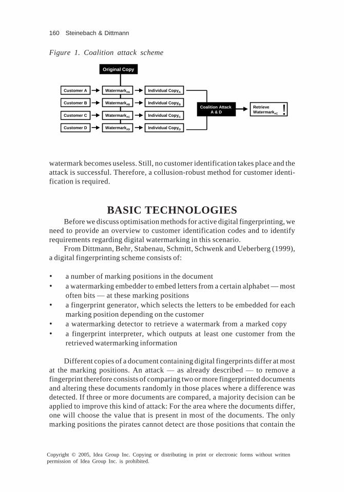
160 Steinebach & Dittmann
Copyright © 2005, Idea Group Inc. Copying or distributing in print or electronic forms without writtenpermission of Idea Group Inc. is prohibited.
watermark becomes useless. Still, no customer identification takes place and theattack is successful. Therefore, a collusion-robust method for customer identi-fication is required.
BASIC TECHNOLOGIESBefore we discuss optimisation methods for active digital fingerprinting, we
need to provide an overview to customer identification codes and to identifyrequirements regarding digital watermarking in this scenario.
From Dittmann, Behr, Stabenau, Schmitt, Schwenk and Ueberberg (1999),a digital fingerprinting scheme consists of:
• a number of marking positions in the document• a watermarking embedder to embed letters from a certain alphabet — most
often bits — at these marking positions• a fingerprint generator, which selects the letters to be embedded for each
marking position depending on the customer• a watermarking detector to retrieve a watermark from a marked copy• a fingerprint interpreter, which outputs at least one customer from the
retrieved watermarking information
Different copies of a document containing digital fingerprints differ at mostat the marking positions. An attack — as already described — to remove afingerprint therefore consists of comparing two or more fingerprinted documentsand altering these documents randomly in those places where a difference wasdetected. If three or more documents are compared, a majority decision can beapplied to improve this kind of attack: For the area where the documents differ,one will choose the value that is present in most of the documents. The onlymarking positions the pirates cannot detect are those positions that contain the
Figure 1. Coalition attack scheme
Customer A Watermark#A
Original Copy
Customer B Watermark#B
Customer C Watermark#C
Customer D Watermark#D
Individual CopyA
Individual CopyB
Individual CopyC
Individual CopyD
Coalition Attack A & D
RetrieveWatermark#C !

Design Principles for Active Audio and Video Fingerprinting 161
Copyright © 2005, Idea Group Inc. Copying or distributing in print or electronic forms without writtenpermission of Idea Group Inc. is prohibited.
same letter in all the compared documents. We call the set of these markingpositions the intersection of the different fingerprints.
The major challenge of active digital fingerprinting is to create a sequenceof bits (or letters) that is robust against these comparisons. Even if the attackerscan identify differences between their copies, mixing the copies must not lead toa copy in which none of the attackers can be identified.
Active FingerprintingTo solve the problem of the coalition attack, we use the Boneh-Shaw
fingerprint and the Schwenk-Ueberberg fingerprint algorithm (Boneh & Shaw,1995; Dittmann et al., 1999). Both algorithms offer the possibility to find thecustomers who have committed the coalition attack. As an application example,we have applied both schemes in a video fingerprinting solution with coalitionresistance in Dittmann, Hauer, Vielhauer, Schwenk and Saar (2001) and ananalysis of the resistants of audio watermarking in Steinebach, Dittmann andSaar (2002). In the following two subchapters we summarize the two fingerprint-ing schemes.
Schwenk Fingerprint SchemeThe Schwenk et al. approach (Dittmann et al., 1999) puts the information
to trace the pirates into the intersection of up to d fingerprints. This allows us inthe best case (e.g., automated attacks like computing the average of finger-printed images) to detect all pirates. In the worst case (removal of individuallyselected marks), we can detect the pirates with a negligibly small one-sided errorprobability; that is, we will never accuse innocent customers.
The fingerprint vector is spread over the marking positions. The markingpositions for each customer are the same in every customer copy and theintersection of different fingerprints can therefore not be detected. With theremaining marked points, the intersection of all used copies, it is possible to followup on all customers who have worked together. Another important parameter isthe number n of copies that can be generated with such a scheme. The schemeuses techniques from finite projective geometry (Beutelspacher & Rosenbaum,1998; Hirschfeld, 1998) to construct d-detecting fingerprinting schemes with q+1possible copies. This scheme needs n=qd+qd-1+...+q+1 marking positions in thedocument. As we see, this can be a huge length and can cause problems with thecapacity of the watermarking scheme. The idea to build the customer vector isbased on finite geometries and the detailed mathematical background will beprovided in the final section.
Boneh-Shaw Fingerprint SchemeThe scheme of Boneh and Shaw (1995) is also used to recognize the
coalition attack, but it is another scheme. Here it is noticeable that we do not
162 Steinebach & Dittmann
Copyright © 2005, Idea Group Inc. Copying or distributing in print or electronic forms without writtenpermission of Idea Group Inc. is prohibited.
necessarily find all pirates, with a (any arbitrary small) probability e that we getthe wrong customer, and each fingerprint has a different number of zeros.
The number of customers is q and with q and e you can get the repeats d.The fingerprint vector consists of (q-1) blocks of the length d (“d-blocks”), andthe total length of the embedded fingerprint computes as d*(q-1). Depending onthe repeats the customer vector can be very long and cause problems with thecapacity of the watermarking algorithm. The idea to build the fingerprintingvector for each customer is simple: The first customer has the value one in allmarked points; for the second customer all marked points without the fist “d-block” are ones; in the third all marked points without the first two “d-blocks” areones, and so forth. The last customer has the value 0 in all marked points.
With a permutation of the fingerprint vector we get a higher security,because the pirates can find differences between the copies, but they cannotassign it to a special d-block. In the final version we provide the detailedmathematical background.
Digital WatermarkingDigital watermarking is in general a method of embedding information into
a cover file. In our case, the cover consists of audio or video files. Depending onthe application scenario, the information embedded will differ. Even the basicconcept of the watermarking algorithms may change, as there are robust, fragileand invertible watermarking schemes (Cox et al., 2001; Dittmann, 2000;Dittmann et al., 2001; Petticolas & Katzenbeisser, 2000). For copyright protec-tion, usually robust watermarking is applied. Still, numerous requirements needto be identified to adjust a watermarking algorithm to a specific scenario. In thissection, we discuss the watermarking requirements with respect to the activefingerprinting application.
Fingerprinting can only take place if the customer is known. This is the casein, for example, Web shop environments, more generally speaking in on-demand-scenarios that require customer authentication. Copies of songs ripped from CDsbought anonymously in stores cannot be marked this way. Embedding afingerprint in an on-demand situation induces a number of requirements to thewatermarking algorithms:
• Transparency is a common requirement for marking digital media in e-commerce environments, as the quality of the content acting as a cover forthe watermark must not be reduced.
• Robustness is necessary against common media operations like lossycompression and format changes.
• Payload must be high enough to include the fingerprint, which usuallyconsists of a long bit vector. This can become a critical requirement.

Design Principles for Active Audio and Video Fingerprinting 163
Copyright © 2005, Idea Group Inc. Copying or distributing in print or electronic forms without writtenpermission of Idea Group Inc. is prohibited.
• Security is of special importance in this case, as the existence of severalcopies of the same cover with different embedded fingerprints enables anumber of specialized attacks commonly called coalition attacks.
• Complexity has to be low enough to enable online and real-time marking.A customer who wants to download a song is not willing to stay online fora long time until his or her personalized copy is available. As there will bemultiple customers at the same time and media data may have a playing timeof an hour or more, either streaming concepts or multiple real-timeembedding speed will be necessary. Furthermore, in most cases non-blindmethods are suitable where the original is needed during retrieval ordetection.
• Verification should be performed in a secret environment. The contentprovider uses a secret watermarking key to embed and retrieve thewatermarks. Customers do not know this key as attackers could easilyverify their success with it.
This scenario-specific list of parameters shows the difference to commoncopyright protection environments: While robustness and transparency are ofsimilar interest, in our scenario payload, security and complexity become moreimportant. As active fingerprinting will only be applied if the content provider hasto be prepared for attacks against more simple customer identification schemes,security is of special interest. One can assume that specialized attacks againstthe watermarks will take place. Complexity needs to be low in comparison toembedding a copyright notice, as in active fingerprinting each copy sold needsto be watermarked. This easily can become a bottleneck if the algorithms are notdesigned accordingly. In general, active fingerprints are much longer thancopyright notes, inducing higher payload requirements in our scenario.
To summarize these observations, it becomes clear that not all watermarkingalgorithms suitable for robust copyright watermarking will be equally suited foractive fingerprinting. Only those algorithms that provide high security, highpayload and a low complexity in addition to a high transparency and goodrobustness may be chosen as a watermarking method.
ADJUSTING WATERMARKING ALGORITHMSTO ACTIVE FINGERPRINTING
To apply active fingerprinting in tracing illegal copies we need a digitalwatermarking algorithm. Current digital watermarking techniques may embedthe generated fingerprinting information redundantly and randomly over themedia file. With a random distribution, the intersection of the proposed finger-prints may be destroyed by coalition attacks. Therefore it is important to ensure

164 Steinebach & Dittmann
Copyright © 2005, Idea Group Inc. Copying or distributing in print or electronic forms without writtenpermission of Idea Group Inc. is prohibited.
that one bit with a certain position in the fingerprint vector is always embeddedat the same place in the media file for every copy. Only then an intersection isundetectable for an attacker.
Audio WatermarkingTo use the properties of the fingerprinting mechanisms to identify the
customers who attacked the watermark we build a watermarking scheme witha fixed number of marking positions in each copy of the audio file (Steinebachet al., 2002). These marking positions can be selected based on a secret key anda psycho-acoustic model to find secure and transparent positions. The finger-printing algorithm generates the fingerprint vector over the binary alphabet{0,1}. The watermarking algorithm embeds this binary vector at the chosenmarking positions.
Watermarking algorithms use different methods to embed a message into acover. The way the message is embedded is relevant for the security of thewatermarking and fingerprinting combination: A PCM audio stream consists ofa sequence of audio samples over time. Our algorithm uses a group of successivesamples, for example, 2048, to embed a single bit of the complete message.Figure 2 illustrates this: The bit sequence 01011 is embedded in a 1-second audiosegment by separating the audio into groups of samples and embedding one bitin each of the segments.
This leads to the following situation: If two different bit vectors areembedded in two copies of the same cover with the same key, the two copiesdiffer exactly in those segments where different bits have been embedded asinformation. Figure 3 shows two embedded bit vectors “01011” and “00001”.Both have been embedded in the same cover audio file. If A and B compare theircopies, they find equal segments at positions 1, 3 and 5 and different segmentsat positions 2 and 4.
Figure 2. Audio watermarking over time
Embed: 0 1 0 1 1
Sam
ple
valu
e
time

Design Principles for Active Audio and Video Fingerprinting 165
Copyright © 2005, Idea Group Inc. Copying or distributing in print or electronic forms without writtenpermission of Idea Group Inc. is prohibited.
Video WatermarkingIn Dittmann et al. (2001) we have introduced for Schwenk Fingerprint
Scheme and the Boneh-Shaw Fingerprint Scheme, a video fingerprinting solutionand the coalition resistance. To mark the video, we generate positions within theframe to embed the watermark information (in the video the positions stand forscenes). Each customer has his or her own fingerprint, which contains a numberof “1” and “0”. Each fingerprint vector is assigned to marking positions in thedocument to prevent the coalition attack. The only marking positions the piratescannot detect are those positions that contain the same letter in all the compareddocuments. We call the set of these marking positions the intersection of thedifferent fingerprints.
Three general problems emerge during the development of the watermark(Dittmann et al., 2001):• Robustness. To improve the robustness against the coalition attack, we
embed one fingerprint vector bit in a whole scene. So we reach a resistanceagainst statistical attacks, like average calculation of look alike frames.With this method we can make the frame cutting and frame changingineffective. We have not contemplated the cutting of a whole scene yet. Inthe current prototype we mark a group of pictures GOP for one fingerprintbit. We add a pseudo-random sequence to the first AC values of theluminance DCT blocks of an intracoded macroblock in all I-Frames of thevideo.
• Capacity. The basis of the video watermark is an algorithm, which wasdeveloped for still images (Dittmann et al., 1999). In still images the wholefingerprint is embedded into the image and the capacity is restricted. Withthe I-Frame in a video, the capacity is much better. To achieve high
Figure 3. Different embedded bit vectors lead to different segments in thecopies
A: 0 1 0 1 1
B: 0 0 0 0 1
= <> = <> =
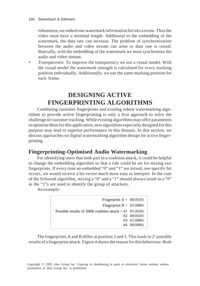
166 Steinebach & Dittmann
Copyright © 2005, Idea Group Inc. Copying or distributing in print or electronic forms without writtenpermission of Idea Group Inc. is prohibited.
robustness, we embed one watermark information bit into a scene. Thus thevideo must have a minimal length. Additional to the embedding of thewatermark, the data rate can increase. The problem of synchronizationbetween the audio and video stream can arise or data rate is raised.Basically, with the embedding of the watermark we must synchronize theaudio and video stream.
• Transparence. To improve the transparency we use a visual model. Withthe visual model the watermark strength is calculated for every markingposition individually. Additionally, we use the same marking position foreach frame.
DESIGNING ACTIVEFINGERPRINTING ALGORITHMS
Combining customer fingerprints and existing robust watermarking algo-rithms to provide active fingerprinting is only a first approach to solve thechallenge of customer tracking. While existing algorithms may offer parametersto optimise them for this application, new algorithms especially designed for thispurpose may lead to superior performance in this domain. In this section, wediscuss approaches on digital watermarking algorithm design for active finger-printing.
Fingerprinting-Optimised Audio WatermarkingFor identifying users that took part in a coalition attack, it could be helpful
to change the embedding algorithm so that a rule could be set for mixing twofingerprints. If every time an embedded “0” and “1” are mixed, one specific bitoccurs, we would receive a bit vector much more easy to interpret. In the caseof the Schwenk algorithm, mixing a “0” and a “1” should always result in a “0”as the “1”s are used to identify the group of attackers.
An example:
The fingerprints A and B differ at position 2 and 5. This leads to 22 possibleresults of a fingerprint attack. Figure 4 shows the reason for this behaviour: Both
Fingerprint A = 0010101
Fingerprint B = 0110001
Possible results of A&B coalition attack = #1 #2 #3 #4
0110101 0010101 0110001 0010001
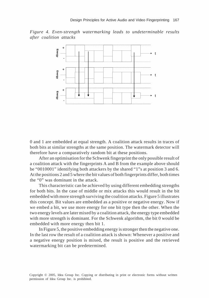
Design Principles for Active Audio and Video Fingerprinting 167
Copyright © 2005, Idea Group Inc. Copying or distributing in print or electronic forms without writtenpermission of Idea Group Inc. is prohibited.
0 and 1 are embedded at equal strength. A coalition attack results in traces ofboth bits at similar strengths at the same position. The watermark detector willtherefore have a comparatively random bit at these positions.
After an optimisation for the Schwenk fingerprint the only possible result ofa coalition attack with the fingerprints A and B from the example above shouldbe “0010001” identifying both attackers by the shared “1”s at position 3 and 6.At the positions 2 and 5 where the bit values of both fingerprints differ, both timesthe “0” was dominant in the attack.
This characteristic can be achieved by using different embedding strengthsfor both bits. In the case of middle or mix attacks this would result in the bitembedded with more strength surviving the coalition attacks. Figure 5 illustratesthis concept. Bit values are embedded as a positive or negative energy. Now ifwe embed a bit, we use more energy for one bit type then the other. When thetwo energy levels are later mixed by a coalition attack, the energy type embeddedwith more strength is dominant. For the Schwenk algorithm, the bit 0 would beembedded with more energy then bit 1.
In Figure 5, the positive embedding energy is stronger then the negative one.In the last row the result of a coalition attack is shown: Whenever a positive anda negative energy position is mixed, the result is positive and the retrievedwatermarking bit can be predetermined.
Figure 4. Even-strength watermarking leads to undeterminable resultsafter coalition attacks
t
En
ergy
+
-
t
En
ergy
+
-
t
En
ergy
+
-

168 Steinebach & Dittmann
Copyright © 2005, Idea Group Inc. Copying or distributing in print or electronic forms without writtenpermission of Idea Group Inc. is prohibited.
EXAMPLE SCENARIO: CINEMAAPPLICATION
Fingerprinting media files today is seen as a promising way of discouragingillegal transfers of copyrighted material. Therefore example scenarios for thistechnology come from media distribution, especially where a small number ofcopies exist but leaking of these copies to the public results in major damage.
One appropriate example is the distribution of movies: In recent times copiesof movies often happen to be available via Internet as illegal copies before or atthe same day they are shown in cinemas. This leads to two possible leaks indistribution:
1. If the movie is available before it is shown in the cinema, some promotionalcopy of the movie may have been used as a master.
2. If the movie is available right when shown in the cinema, someone may haverecorded it with a small video camera.
Tracing illegal copies is more difficult in (2) then in (1). The two leaksstrongly differ with regards to the watermarking parameters:
• Robustness in (1) is only necessary against digital video format change ifthe promotion copy is on DVD, or against high-quality digitisation if thecopy is on videotape. Leak (2) requires robustness against a low qualityanalogue to digital conversion, as the movie is recorded by a small digitalcamera in a noisy surrounding.
Figure 5. Different watermarking strengths for 0 and 1 lead to predeterminedresults after coalition attacks
t
En
ergy
+
-
t
En
ergy
+
-
t
En
ergy
+
-

Design Principles for Active Audio and Video Fingerprinting 169
Copyright © 2005, Idea Group Inc. Copying or distributing in print or electronic forms without writtenpermission of Idea Group Inc. is prohibited.
• Transparency, on the other hand, needs to be higher or at least more reliablein (2) than in (1), as a low audio or video quality caused by embedding thewatermark will not be accepted by movie theatres and customers.
• The required payload of the watermark may also be higher in (2) than in (1),as one can assume there will be fewer promotional copies than actual moviecopies for the cinemas. This leads to more individual customers to beidentified by the fingerprints, making them significantly longer.
While, therefore leak (2) may be more challenging then (1), both can beaddressed with the same strategy:
• Create a movie master• Create the required amount of fingerprinted copies from this master• Distribute the fingerprinted copies• Search for occurring illegal copies• Retrieve the fingerprint from the copy• Identify the leak with the help of the fingerprint
Attacks against Fingerprinted CopiesAs a movie consists of video as well as audio information, watermarking
algorithms for both media types can be used for fingerprint embedding. While thewatermarking algorithms may be able to satisfy all the scenario-dependentrequirements stated above, the fingerprint may also be subject to specializedattacks as soon as it becomes known to the public that fingerprinting is used fortracing copies. This is unavoidable if discouragement is desired.
Let us assume we fingerprint promotional DVDs for tracing leaks (1) usingan MPEG video watermark. Two recipients of the promotional copies wantingto distribute illegal copies and willing to work together now can start coalitionattacks to remove or corrupt the fingerprints.
The coalition security implies, for example, the following attacks:
(a) Attacks to separate frame areas(b) Attacks to whole frame(c) Attacks to whole scenes
The time and practical effort grows from (a) to (c). The video must be splitin the important areas. Additionally there must be knowledge about the MPEGvideo format. The attack over whole frames, like the exchange of frames, is onlypossible with visually similar frames, because with different frames the seman-tics of the frames can be destroyed. Only for attacks over whole scenes thewatermark has no robustness, because one bit of the fingerprint vector will be

170 Steinebach & Dittmann
Copyright © 2005, Idea Group Inc. Copying or distributing in print or electronic forms without writtenpermission of Idea Group Inc. is prohibited.
cut out. But with the cut off of whole scenes the semantics of the video will bedecreased.
Optimisation PotentialTo be less vulnerable against coalition attacks, we introduced a strategy for
fingerprinting-optimised audio watermarking in this chapter. This strategy can beapplied in the cinema-application if a certain loss of audio quality is acceptable,which may be the case in promotional copy distribution.
First test results with embedding the bits 0 and 1 of the audio watermark withdifferent energy are promising. Depending on the energy difference, error ratesafter coalition attacks are reduced by up to 50%. Error rates have beencalculated by counting the number of times bit 1 has been replaced by bit 0 aftera coalition attack.
Figure 6 shows that the reduction of error rates is related to the increase ofenergy difference between bit 0 and bit 1. If both are embedded at equal strength(0 dB difference), the error rate is above 50%. On the other hand, at a differenceof 12 dB, almost no errors occurred.
If the quality loss caused by the strong watermark for bit 1 can be accepted,embedding watermark bits with differing energy seems to be an improvementregarding robustness against coalition attacks. In our example, to reduce theerror rate below 10%, we would need an embedding difference of 6 dB, whichproduces a quality loss similar to mp3 encoding at 192 kbps. This should beacceptable for a huge number of applications.
Figure 6. Error rates of fingerprints
0
10
20
30
40
50
60
0 3 4.5 6 12
0/1 difference (dB)
erro
r ra
te (%
)

Design Principles for Active Audio and Video Fingerprinting 171
Copyright © 2005, Idea Group Inc. Copying or distributing in print or electronic forms without writtenpermission of Idea Group Inc. is prohibited.
SUMMARY AND CONCLUSIONSAltogether, digital watermarking to embed fingerprinting information is a
pragmatic approach to discourage the illegal use of the copied data. The widevariety of existing watermarking algorithms reflects the business relevance.Beside the robustness to common media transformations, coalition attacks raiseimportance and become a critical factor for example in the design of cinemaapplications. As, for example, a special session “Cinema application” at SPIE2003 shows, the combination of secure fingerprint schemes and the watermarkingalgorithms itself seems to be still an open problem. Reasons are in most casesthe limited capacity for embedding the collusion secure fingerprint as well assynchronisation problems.
Besides the development of watermarking algorithms and collusion securefingerprint vector design our future goal is to design interactive tools thatstrengthen the producers’ acceptance to use digital watermarking techniques tooffer their data in a more secure way in the digital marketplace.
REFERENCESAllamanche, E., Herre, J., Helmuth, O., Fröba, B., Kasten, T., & Cremer, M.
(2001). Content-based identification of audio material using MPEG-7 lowlevel description. Proceedings of the International Symposium of MusicInformation Retrieval.
Beutelspacher, A., & Rosenbaum, U. (1998). Projective geometry. CambridgeUniversity Press.
Boneh, D., & Shaw, J. (1995). Collusion-secure fingerprinting for digital data.Proceedings of CRYPTO’95, LNCS 963, (pp. 452-465). Springer.
Cox, I., Miller, M., & Bloom, J. (2002). Digital watermarking, ISBN 1-55860-714-5. San Diego, CA: Academic Press.
Dittmann, J. (2000). Digitale wasserzeichen, ISBN 3-540- 66661-3. SpringerVerlag.
Dittmann, J., Behr, A., Stabenau, M., Schmitt, P., Schwenk, J., & Ueberberg, J.(1999). Combining digital watermarks and collusion secure fingerprints fordigital images. Proceedings of SPIE, 3657, (pp. 3657-51). San Jose, CA:Electronic Imaging.
Dittmann, J., Hauer, E., Vielhauer, C., Schwenk, J., & Saar, E. (2001). Customeridentification for MPEG video based on digital fingerprints. Proceedingsof Advances in Multimedia Information Processing - PCM 2001, TheSecond IEEE Pacific Rim Conference on Multimedia, Beijing, China,ISBN 3-540-42680-9, (pp. 383-390). Berlin: Springer Verlag.
Dittmann, J., Wohlmacher, P., & Nahrstedt, K. (2001, October-December).Multimedia and security – Using cryptographic and watermarking algo-rithms. ISSN 1070-986X IEEE MultiMedia, 8(4), 54-65.
172 Steinebach & Dittmann
Copyright © 2005, Idea Group Inc. Copying or distributing in print or electronic forms without writtenpermission of Idea Group Inc. is prohibited.
Haitsma, J., Kalker, T., & Oostveen, J. (2001). Robust audio hashing for contentidentification. Proceedings of the Content-Based Multimedia Indexing.
Hirschfeld, J.W.P. (1998). Projective geometries over finite fields (2nd ed.).Oxford University Press.
Petticolas, F., & Katzenbeisser, S. (2000). Information hiding techniques forsteganography and digital watermarking. Artech House ComputerSecurity Series, ISBN: 1580530354.
Pfitzmann, A., Federrath, J., & Kuhn, M. (2002). DRM-studie dmmv-technischer teil.
Steinebach, M., Dittmann, J., & Saar, E. (2002, September 26 - 27). Combinedfingerprinting attacks against digital audio watermarking: Methods, resultsand solutions. In B. Jerman-Blazic & T. Klobucar (Eds.), Proceedings ofAdvanced Communications and Multimedia Security, IFIP TC6 / TC116th Joint Working Conference on Communications and MultimediaSecurity, Portoroz, Slovenia (pp. 197 - 212, ISBN 1-4020-7206-6). KluwerAcademic Publishers.
Issues on Image Authentication 173
Copyright © 2005, Idea Group Inc. Copying or distributing in print or electronic forms without writtenpermission of Idea Group Inc. is prohibited.
Chapter VI
Issues onImage Authentication
Ching-Yung Lin, IBM T.J. Watson Research Center, USA
ABSTRACTMultimedia authentication distinguishes itself from other data integritysecurity issues because of its unique property of content integrity in severaldifferent levels — from signal syntax levels to semantic levels. In thissection, we describe several image authentication issues, including themathematical forms of optimal multimedia authentication systems, adescription of robust digital signature, the theoretical bound of informationhiding capacity of images, an introduction of the self-authentication-and-recovery image (SARI) system, and a novel technique for image/videoauthentication in the semantic level. This chapter provides an overview ofthese image authentication issues.
INTRODUCTIONThe well-known adage that “seeing is believing” is no longer true due to the
pervasive and powerful multimedia manipulation tools. Such development hasdecreased the credibility that multimedia data such as photos, video or audioclips, printed documents, and so forth used to command. To ensure trustworthi-ness, multimedia authentication techniques are being developed to protectmultimedia data by verifying the information integrity, the alleged source of data,and the reality of data. This distinguishes from other generic message authenti-cation in its unique requirements of integrity. Message authentication tech-niques usually cannot allow any single bit of data change. However, multimedia

174 Lin
Copyright © 2005, Idea Group Inc. Copying or distributing in print or electronic forms without writtenpermission of Idea Group Inc. is prohibited.
data are generally compressed and quality enhanced. Thus, accepting lossycompressed multimedia and some content-preserving filtering is an essentialrequirement in many applications.
Multimedia authentication distinguishes itself from other data integritysecurity issues because of its unique property of content integrity in severaldifferent levels - from signal syntax levels to semantic levels. In contrast to thedata integrity issues that do not allow any changes on the data, multimedia canbe considered as authentic if it is manipulated in a sense that its “content” ispreserved. Content, which is an ambiguous concept, can indicate severaldifferent meanings of multimedia data. Figure 1 shows several layers of contentdescription (Jaimes & Chang, 2000). Among them, the first three layers in thesyntax level may be explicitly described by machines. For instance, compression,filtering, or some other signal level manipulations can be explicitly modeled.Thus, it is possible to clearly distinguish them from malicious manipulations, suchas crop-and-replacement, without any false alarm and with a negligible miss rate(Lin & Chang, 2001). However, an authentication system based on syntax-levelmodeling may meet its limits if the overall manipulation is a combination ofvarious types of acceptable changes and the final manipulated multimedia dataare still similar to the original in the semantic sense. For instance, a picture ofPresident Clinton and the First Lady walking on the lawn may be semanticallyauthentic even if the color of lawn changes or some background trees areremoved, as long as the head of the First Lady is not changed. Therefore, weconsider a semantic authentication system that checks the semantic content isrequired and is closer to the way human beings conduct authentication.
Several syntax level authentication methods have been discussed. Schneiderand Chang first proposed the concept of salient feature extraction and similaritymeasure for image content authentication (Schneider & Chang, 1996). They alsodiscussed issues of embedding such signatures into the image. However, theirwork lacked a comprehensive analysis of adequate features and embeddingschemes. Bhattacha and Kutter proposed a method that extracts “salient” imagefeature points by using a scale interaction model and Mexican-hat wavelets(1998). Queluz proposed techniques to generate digital signature based onmoments and edges of an image (Queluz, 1999). Fridrich divided images into64x64 pixel blocks. For each block, quasi-VQ codes were embedded using thespread spectrum method (Fridirch, 1998). Lu and Liao proposed several schemesfor structured digital signatures for authentication. Lin and Chang proposed aunique self-authentication-and-recovery image (SARI) system (2001). SARIutilizes a semi-fragile watermarking technique that distinguishes acceptableJPEG lossy compression, brightness and contrast changes from maliciousattacks. The authenticator can identify the positions of corrupted blocks, andrecover them with approximations of the original ones. SARI is based on theinvariant feature codes and the zero-error information hiding capacity of images.
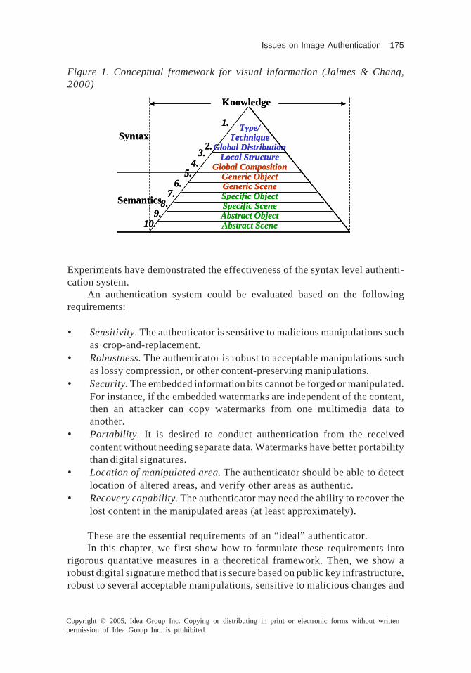
Issues on Image Authentication 175
Copyright © 2005, Idea Group Inc. Copying or distributing in print or electronic forms without writtenpermission of Idea Group Inc. is prohibited.
Experiments have demonstrated the effectiveness of the syntax level authenti-cation system.
An authentication system could be evaluated based on the followingrequirements:
• Sensitivity. The authenticator is sensitive to malicious manipulations suchas crop-and-replacement.
• Robustness. The authenticator is robust to acceptable manipulations suchas lossy compression, or other content-preserving manipulations.
• Security. The embedded information bits cannot be forged or manipulated.For instance, if the embedded watermarks are independent of the content,then an attacker can copy watermarks from one multimedia data toanother.
• Portability. It is desired to conduct authentication from the receivedcontent without needing separate data. Watermarks have better portabilitythan digital signatures.
• Location of manipulated area. The authenticator should be able to detectlocation of altered areas, and verify other areas as authentic.
• Recovery capability. The authenticator may need the ability to recover thelost content in the manipulated areas (at least approximately).
These are the essential requirements of an “ideal” authenticator.In this chapter, we first show how to formulate these requirements into
rigorous quantative measures in a theoretical framework. Then, we show arobust digital signature method that is secure based on public key infrastructure,robust to several acceptable manipulations, sensitive to malicious changes and
Type/Technique
Global DistributionLocal Structure
Global CompositionGeneric ObjectGeneric SceneSpecific ObjectSpecific SceneAbstract ObjectAbstract Scene
Knowledge
1.
10.
2.3.
4.5.
6.7.
8.9.
Syntax
Semantics
Type/Technique
Global DistributionLocal Structure
Global CompositionGeneric ObjectGeneric SceneSpecific ObjectSpecific SceneAbstract ObjectAbstract Scene
Knowledge
1.
10.
2.3.
4.5.
6.7.
8.9.
Syntax
Semantics
Figure 1. Conceptual framework for visual information (Jaimes & Chang,2000)

176 Lin
Copyright © 2005, Idea Group Inc. Copying or distributing in print or electronic forms without writtenpermission of Idea Group Inc. is prohibited.
able to detect the manipulated area. Next, we will have a brief introduction ofwatermarking and then show the solution of an important issue in watermarking— what is the upper bound of embedding watermark codes in an image such thatthe watermark information is guaranteed to be reconstructible in amplitude-bounded noisy environments.
Using the techniques for embedded error-free watermark codes in images,we show a self-authentication-and-recovery image (SARI) watermarking sys-tem. SARI utilizes a novel semi-fragile watermarking technique that acceptsquantization-based lossy compression to a quantifiable quality level and somecontent-preserving manipulations on the watermarked image, and rejects mali-cious attacks. The authenticator can identify the positions of corrupted blocks,and recover them with approximation of the original ones. The security of theproposed method is achieved by utilizing the public key infrastructure. SARIsystem provides solutions to two major challenges in developing authenticationwatermarks: how to extract short, robust and invariant information to substitutefragile image-based hash functions, and how to embed information that isguaranteed to survive quantization-based lossy compression. Also, recovery bitsare generated and embedded for recovering approximate pixel values in cor-rupted areas.
In the last part of this chapter, we describe a novel technique for image/video authentication in the semantic level. This method uses statistical learning,visual object segmentation and classification schemes for semantic understand-ing of visual content. Then, we further embed either the classification output orthe user annotated model labels into multimedia data as watermarks. A robustrotation, scaling, and translation public watermarking method is used for embed-ding information (Lin, Wu, Bloom, Miller, Cox, & Lui, 2001). The authenticationprocess is executed by comparing the classification result with the informationcarried by the watermark. This method leads the authentication system to learnthe semantic content of multimedia data and perform authentication tasks in amodel-based semantic level.
CHARACTERISTICS OFMULTIMEDIA AUTHENTICATION SYSTEM
Multimedia authentication is centered on an extended detection issue, butinvolves more parties and more measures than traditional detection problems. Ageneric detection system, such as a radar system that detects missile attack, ora pattern recognition system that detects specific fish, considers the systemperformance from the detector’s point of view. These detectors make decisionsbased on the features of collected data. They cannot interfere in the features, forexample, time of the appearance of missiles or the size, shape and weight of fish.

Issues on Image Authentication 177
Copyright © 2005, Idea Group Inc. Copying or distributing in print or electronic forms without writtenpermission of Idea Group Inc. is prohibited.
In general, classic detection theorems consider only two measures, the probabili-ties of miss and false alarm, and the Neyman-Pearson criteria, usually appliedto determine the operating points on the receiver operating characteristic (ROC)plot.
On the other hand, an authentication system involves three active parties:the watermark embedder, the authenticator, and the attacker. In an authen-tication system, the embedders interfere in the features of the collected data.This makes a multimedia authentication system involve the characteristics ofcommunication, signal detection and security. The authenticator plays a tradi-tional role of detector, which can be evaluated by the probabilities of miss andfalse alarm. For the embedder, the evaluation metric is mainly related to thevisual quality of the watermark-embedded images. When we consider theattacker’s role in evaluating the overall multimedia authentication system, we aremainly concerned with the probability of successful attack, based on theparameters chosen by the watermark embedder, authenticator, and the level ofattacker’s knowledge about the secret information in the system. In summary,we need four measures: the visual quality of watermarked image at embedder,Q
I, the probability of false alarm (in mistaking acceptable manipulations at
authenticator), PFA
, the probability of miss (in detecting malicious manipula-tions at authenticator), P
M, and the probability of successful attack by attacker,
PS, for a multimedia authentication watermarking system. In addition, how easily
an attacker acquires knowledge can be interpreted related to the security levelof the system. This may be measured by the computation required to breakcryptographic keys and the possible breaking points of system protocol (Schneier,1996). To our knowledge, how to measure security level quantatively in amultimedia authentication system is still an open issue.
We can measure QI by peak signal-noise ratio (PSNR) or just-noticeable
distortion (JND). PSNR is well known for its advantage of computationalefficiency and the disadvantage of not being able to reflect subjective imagequality properly. JND is a measure that indicates the visibility of the changes toa pixel, an area, or the whole frames between two images in comparison (Lu &Liao, 2003; Watson, 1993). The fact that some coefficient changes are notnoticeable is due to the human vision masking effect. The maximum unnoticeablechanges (or equivalently, the minimal noticeable changes) are called masks,which represent 1 JND. A more detailed discussion of JNDs can be found in Lin(2000).
From the authenticator’s point of view, authentication is a hypothesis testbased on the observed data, Z, which is obtained after manipulations of an image, I:
Hypothesis 1 (H1): Z = M
A( I )
Hypothesis 2 (H2): Z = M
N( I )

178 Lin
Copyright © 2005, Idea Group Inc. Copying or distributing in print or electronic forms without writtenpermission of Idea Group Inc. is prohibited.
and a specific classifier, g( ), is used to decide which hypothesis is true. MA( )
and MN( ) represent acceptable and unacceptable manipulations, respectively.
Then, the probability of false alarm, PFA
and PM
can be expressed as:
PFA
= E[ P( g(Z) = 2 | H1) ] = E[ P(g(Z) = 2 | M
A( I ) ) ], (1)
and
PM
= E[ P( g(Z) = 1 | H2) ] = E[ P( g(Z) = 1 | M
N( I ) ) ]. (2)
The expectation value is measured over the probability distributions of H1
or H2. These probabilities are measures of each fixed classifier, because the
authenticator chooses a specific classifier to optimize performance. Equations(1) and (2) are modeled from the classic statistical point of view. From theBayesian theories’ viewpoints, the instances of the given item and the classifieritems are reversed and the classifiers are random 0. Bayesian theories considertwo priors, P(H
1= true) = p
1, and P(H
2= true) = 1 – p
1 = p
2, are available, while
classic statistical theories did not acknowledge the existence of these twoprobabilities.
For the authenticator, the discrimination classifier, g, is fixed and optimizedbased on the parameters sent by the embedder. On the other hand, we assumethe attacker may assume a specific classifier based on the best knowledge orassume random classifiers in the case of lacking embedder knowledge. Withoutknowledge about the attacker’s approaches, we may assume the attacker’smethod comes from a random pool, G. The probability of the attacker’s successcan be represented as:
PS = E[ P( GΘΘΘΘΘ
(Z) = 1 | MN0
( I )) ], (3)
that is, the probability of the attacker’s success is an expectation value. InEquation (3), ΘΘΘΘΘ is treated as a random variable and its probability distributionfunction (pdf) is a subjective prior measure about how much knowledge theattacker has about the security of the system. A subjective pdf clearly point outthat P
S is the degree of belief of the attacker but not the physical property of
an event 0. Different levels of security knowledge can be indicated by differentprobability distribution functions of ΘΘΘΘΘ, that is, f(ΘΘΘΘΘ) can be modeled as a deltafunction, which is one at the true value of ΘΘΘΘΘ and zero elsewhere, if the attackerknows exactly how the authenticator authenticates the image. We should notethat P
S is a measure of a known fixed manipulation to the attacker.
An authentication system wishes to minimize the probabilities of false alarm,miss, and attack success subject to constraints on the visual quality of embedded
Issues on Image Authentication 179
Copyright © 2005, Idea Group Inc. Copying or distributing in print or electronic forms without writtenpermission of Idea Group Inc. is prohibited.
image. If there are penalties (costs) of each probability, then the total cost of thesystem can be represented by:
CQ = c
1 E[P
FA] + c
2 E[P
M] + c
3 E[P
S ]. (4)
where we take the expectation of PFA
, PM
and PS based on prior probabilities of
various manipulation and attack types, and c1, c
2 , and c
3 are costs of the three
kinds of errors. There are no universal models for these prior probabilities. Someexamples and analyses of them can be seen in Lin and Chang (2001).
Theoretically, we can extend Neyman-Pearson criteria to get an operatingpoint (of these three probabilities) for the authentication system, based on themaximally tolerable quality degradation:
qi = arg
QI min C
Q (5)
In general, as the embedded code length increases, the three probabilities,P
FA, P
M and P
S decrease while the image quality is fixed. The information hiding
capacity of an image is the critical operational point of the system. There are nogeneral-form solutions to Equations (4) and (5). But, given the information hidingcapacity, if we model manipulations and attacks using Gaussian distributions andmodel quality loss using PSNR, we then can obtain closed form answers of them,although we may have over-simplified the calculations via assuming a lot of priorprobabilities.
ROBUST DIGITAL SIGNATUREThe digital signature method introduced by Diffie and Hellman in 1976
provides a technique to verify the integrity and the alleged source of datasimultaneously. If machines play the role of signer, as the trustworthy cameratechnique proposed by Friedman in 1993, digital signatures may provide a senseof reality. We should note that the trustworthiness of the signers is always aconcern. Because multimedia data are usually distributed, transcoded, andreinterpreted by many interim entities (e.g., editors, agents), it becomes impor-tant to guarantee end-to-end trustworthiness between the origin source and thefinal recipient. Figure 2 shows a comparison of systems using traditional digitalsignatures (TDS) and robust digital signatures (RDS). RDS-based systemreduces both the required number of trusted intermediate parties and the risk offorgery. It also verifies authenticity directly from the original machine signer,which could, in a sense, provide a proof of reality.
A simple structure of RDS algorithm is shown in Figure 3. An RDS is anencrypted form of the feature codes of the multimedia data. When a user needsto authenticate the received data, he should decrypt this signature and compare

180 Lin
Copyright © 2005, Idea Group Inc. Copying or distributing in print or electronic forms without writtenpermission of Idea Group Inc. is prohibited.
the feature codes to their corresponding values in the signature. If the derivedfeature codes match the range space of the original feature codes afteracceptable manipulations, this multimedia data is said to be “authentic”. How toextract (short) feature codes that are invariant to acceptable manipulations butsensitive to malicious changes is the main challenge of RDS.
We found that some strictly quantitative invariants and predictable proper-ties can be extracted when multimedia data was transcoded by quantization-based compressions. For instance, because all DCT coefficient matrices ofimages are divided by the same quantization table in the JPEG compressionprocess, the relationship between two DCT coefficients of the same coordinate
Editor 1 Transcoder 2Transcoder 1
Editor X Transcoder YTx Rx
Tx RxEditor 1 Transcoder 2Transcoder 1
Editor X Transcoder YTx Rx
Tx Rx
RDS
verification
trust
(b)
Editor 1 Transcoder 2Transcoder 1
Editor X Transcoder YTx Rx
Tx Rx
verification verification
verificationverificationverification
verificationtrust
trust trust trust
trust trust
TDS1 TDS2 TDS3
TDSn-2 TDSn-1 TDSn
(a)
Editor 1 Transcoder 2Transcoder 1
Editor X Transcoder YTx Rx
Tx RxEditor 1 Transcoder 2Transcoder 1
Editor X Transcoder YTx Rx
Tx Rx
RDS
verification
trust
(b)
Editor 1 Transcoder 2Transcoder 1
Editor X Transcoder YTx Rx
Tx RxEditor 1Editor 1 Transcoder 2Transcoder 1
Editor XEditor X Transcoder YTx Rx
Tx RxEditor 1 Transcoder 2Transcoder 1
Editor X Transcoder YTx Rx
Tx RxEditor 1Editor 1 Transcoder 2Transcoder 1
Editor XEditor X Transcoder YTx Rx
Tx Rx
RDS
verification
trust
(b)
Editor 1 Transcoder 2Transcoder 1
Editor X Transcoder YTx Rx
Tx Rx
verification verification
verificationverificationverification
verificationtrust
trust trust trust
trust trust
TDS1 TDS2 TDS3
TDSn-2 TDSn-1 TDSn
(a)
Editor 1Editor 1 Transcoder 2Transcoder 1
Editor XEditor X Transcoder YTx Rx
Tx Rx
verification verification
verificationverificationverification
verification verificationverification verificationverification
verificationverificationverificationverificationverificationverification
verificationverificationtrust
trust trust trust
trust trust
TDS1 TDS2 TDS3
TDSn-2 TDSn-1 TDSn
(a)
Figure 2. Multimedia authentication: (a) Using traditional digital signatures(TDS) – Trust all parties and verify multiple digital signatures; (b) Usingrobust digital signature (RDS) – Trust only the original signer and verifysingle signature
Digital Camera
Image/Video/Audio Private Key Encrypted
Digital Signature
Image/Video
Authenticator
Digital Signature
Image/Video/Audio
Public Key DecryptedComparator
Result
Feature Codes
Generator
Pseudo Feature Codes Generator
Digital Camera
Image/Video/Audio Private Key Encrypted
Digital Signature
Image/Video
Authenticator
Digital Signature
Image/Video/Audio
Public Key DecryptedPublic Key DecryptedComparator
Result
Feature Codes
Generator
Pseudo Feature Codes Generator
Figure 3. Generation and authentication of robust digital signatures

Issues on Image Authentication 181
Copyright © 2005, Idea Group Inc. Copying or distributing in print or electronic forms without writtenpermission of Idea Group Inc. is prohibited.
position should remain the same after the quantization process. Furthermore, dueto the rounding effect after quantization, the relationship of the two may be thesame or become equal. In other words, if one coefficient Fp(n) in the position nof block p is larger than the other coefficient Fq(n) in the position n of block q,then after compression, their relationship, Fp’(n)≥Fq’(n), where Fp’(n) = IntegerRound (Fp(n)/Q)×Q and Fq’(n) = Integer Round (Fq(n)/Q)×Q, is guaranteed.It can be summarized as Theorem 1:
Theorem 1:• if Fp(n) > Fq(n) then Fp’(n) ≥ Fq’(n) ,• if Fp(n) < Fq(n) then Fp’(n) ≤ Fq’(n) ,• if Fp(n) = Fq(n) then Fp’(n) = Fq’(n).
This property holds for any number of decoding, re-encoding processes, aswell as intensity and contrast changes.
The signature generation process is as follows: each 8×8 block of an imagecaptured is transformed to the DCT coefficients, and sent to the image analyzer.The feature codes are generated according to two crypto key-dependentcontrollable parameters: mapping function, W, and selected positions, b. Givena block p in an image, the mapping function is used for selecting the other blockto form a block pair, that is, q = W(p). A coefficient position set, b, is used toindicate which positions in an 8×8 block are selected. The feature codes of theimage records the relationship of the difference value, Fp(n)-Fq(n) at the bselected positions. This process is applied to all blocks to ensure the whole imageis protected. In the last step, the feature codes are encrypted with a private keyby using the public key encryption method.
Given a signature derived from the original image and a JPEG compressedimage bitstream, for authentication, at the first step, we have to decrypt thesignature and reconstruct DCT coefficients. Because the feature codes de-crypted from the signature record the relationship of the difference values andzero, they indicate the sign of the difference of DCT coefficients, despite thechanges of the coefficients incurred by lossy JPEG compression. If theseconstraints are not satisfied, we can claim that this image has been manipulatedby another method.
Some parameters can be used to allow this system to be applied in varioussituations. For instance, we can set tolerance bounds on the authenticator toallow systems to accept some other minor manipulations, such as low-passfiltering, median filtering, and so forth. Or, multilayer feature codes can be usedto increase the security and sensitivity of the system.
Similar to the image authentication system, video authentication signaturesthat are robust to the transcoding processes can be generated. Systems cangenerate RDS based on different transcoding application scenario: for example,

182 Lin
Copyright © 2005, Idea Group Inc. Copying or distributing in print or electronic forms without writtenpermission of Idea Group Inc. is prohibited.
dynamic rate shaping, rate control with/without drift error correction, consistent/inconsistent frame types transcoding, and so forth.
WATERMARKING CAPACITYFOR DIGITAL IMAGES
In watermarking schemes, multimedia data are considered as a communi-cation channel to transmit messages. An important theoretical issue ofwatermarking is: how much information can be reliably transmitted as water-marks without causing noticeable quality losses?
Theoretical capacity issues of digital watermarking have not been fullyunderstood. Most of the previous works on watermarking capacity (e.g., Barn,Bartolini, De Rosa, & Piva, 1999; Queluz, 1999; Servetto, Podilchuk, &Ramchandran, 1998) directly apply Shannon’s well-known channel capacitybound:
)1(log2
12 N
PC += (6)
which provides a theoretic capacity bound of an analog-value time-discretecommunication channel in a static transmission environment, that is, where the(codeword) signal power constraint, P, and the noise power constraint, N, areconstants (Shannon, 1948). Transmitting message rate at this bound, theprobability of decoding error can approach zero if the length of codewordapproaches infinite, which implies that infinite transmission samples are ex-pected.
Considering multimedia data, we found there are difficulties if we directlyapply Equation (6). The first is the number of channels. If the whole image is achannel, then this is not a static transmission environment because the signalpower constraints are not uniform throughout the pixels, based on the humanvision properties. If the image is a composition of parallel channels, then thiscapacity is meaningless because there is only one or few sample(s) in eachchannel. The second difficulty is the issue of digitized values in the multimediadata. Contrary to floating point values, which have infinite states, integer valuehas only finite states. This makes a difference in both the applicable embeddingwatermark values and the effect of noises. The third obstacle is that we will notknow how large the watermark signals can be without an extensive study ofhuman vision system models, which is usually ignored in most previouswatermarking research, perhaps because of its difficulties and complexity. Thefourth hurdle is related to noise modeling.
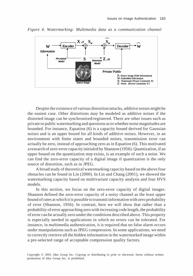
Issues on Image Authentication 183
Copyright © 2005, Idea Group Inc. Copying or distributing in print or electronic forms without writtenpermission of Idea Group Inc. is prohibited.
Despite the existence of various distortion/attacks, additive noises might bethe easiest case. Other distortions may be modeled as additive noises if thedistorted image can be synchronized/registered. There are other issues such asprivate or public watermarking and questions as to whether noise magnitudes arebounded. For instance, Equation (6) is a capacity bound derived for Gaussiannoises and is an upper bound for all kinds of additive noises. However, in anenvironment with finite states and bounded noises, transmission error canactually be zero, instead of approaching zero as in Equation (6). This motivateda research of zero-error capacity initialed by Shannon (1956). Quantization, if anupper bound on the quantization step exists, is an example of such a noise. Wecan find the zero-error capacity of a digital image if quantization is the onlysource of distortion, such as in JPEG.
A broad study of theoretical watermarking capacity based on the above fourobstacles can be found in Lin (2000). In Lin and Chang (2001), we showed thewatermarking capacity based on multivariant capacity analysis and four HVSmodels.
In this section, we focus on the zero-error capacity of digital images.Shannon defined the zero-error capacity of a noisy channel as the least upperbound of rates at which it is possible to transmit information with zero probabilityof error (Shannon, 1956). In contrast, here we will show that rather than aprobability of error approaching zero with increasing code length, the probabilityof error can be actually zero under the conditions described above. This propertyis especially needed in applications in which no errors can be tolerated. Forinstance, in multimedia authentication, it is required that no false alarm occursunder manipulations such as JPEG compression. In some applications, we needto correctly retrieve all the hidden information in the watermarked image withina pre-selected range of acceptable compression quality factors.
S: Source Image (Side Information)W: Embedded InformationX: Watermark (Power Constraint: P)Z: Noise (Power Constraint: N )
W Encoder
S
Decoder W
Z ≤ N
Source Image
Information
SwX ≤ P Sw
PerceptualModel
Private/ Public
DistortionModel
S: Source Image (Side Information)W: Embedded InformationX: Watermark (Power Constraint: P)Z: Noise (Power Constraint: N )
W Encoder
S
Decoder W
Z ≤ N
Source Image
Information
SwX ≤ P Sw
PerceptualModel
Private/ Public
DistortionModel
W Encoder
S
Decoder W
Z ≤ N
Source Image
Information
SwX ≤ P Sw
PerceptualModel
Private/ Public
DistortionModel
Figure 4. Watermarking: Multimedia data as a communication channel

184 Lin
Copyright © 2005, Idea Group Inc. Copying or distributing in print or electronic forms without writtenpermission of Idea Group Inc. is prohibited.
In this section, we will also show that the semi-fragile watermarking methodthat we proposed in Lin and Chang (2000) is, in fact, one way of achieving thezero-error capacity. We will also show two sets of curves that represent thezero-error capacity. Although most of our discussion will focus on imagewatermarking subject to JPEG manipulation, the zero-error capacity we showedhere can be applied to other domains as long as the noise magnitude isconstrained.
We first discuss the meaning and classification of channels in an image.Then, we will discuss a theoretical derivation of zero-error capacity of a discretememoryless channel and an image. We will then show the capacity curves andsome experiments results.
Number of Channels in an ImageHere we consider the case that the maximal acceptable level of lossy
compression is pre-determined. In JPEG, maximum distortion of each DCTcoefficient is determined by the quantization step size. Since JPEG uses the samequantization table in all blocks, maximum distortion just depends on the positionin the block and is the same for all coefficients from different blocks but at thesame position. If we define a pre-selected lower bound of acceptable compres-sion quality factors, then all the quantization step size at any specific position ofblocks will be smaller than or equal to the quantization step size from the selectedlowest quality factor (Lin &Chang, 2000).
Assume a digital image X has M×N pixels that are divided into B blocks.Here, in the blocked-based DCT domain, X may be considered as
• Case 1. A variant-state discrete memoryless channel (DMC). Transmis-sion utilizes this channel for M×N times.
• Case 2. A product of 64 static-state DMCs, in which all coefficients in thesame position of blocks form a DMC. Each channel can be at mosttransmitted B times. In other words, the maximum codeword length is B foreach channel.
• Case 3. A product of M×N static-state DMCs, in which each coefficientforms a DMC. Each channel can be at most transmitted once.
In most information theory research works, channel is usually consideredinvariant in time and has uniform power and noise constraint, which is usuallyvalid in communication. Time variant cases have been addressed (e.g., Csiszar& Narayan, 1991), called arbitrarily varying channel (AVC). However, sucha work on AVC may not be adequate to the watermarking problem because thechannel does not vary in a statistically arbitrary way.
We think that Case 2 is the best candidate for the capacity analysis problemif the image is only manipulated by JPEG. However, assuming no error
Issues on Image Authentication 185
Copyright © 2005, Idea Group Inc. Copying or distributing in print or electronic forms without writtenpermission of Idea Group Inc. is prohibited.
correction codes are used in this zero-error environment, the codes in Case 2 willbe sensitive to local changes. Any local changes may cause loss of the wholetransmitted information in each channel. In applications in which information bitshave to be extracted separately from each block, Case 3 may be the bestcandidate. For instance, in the authentication case, some blocks of the image maybe manipulated. By treating each coefficient as a separate channel (as in Case 3), wecan detect such manipulations in a local range.
A general watermarking model is shown in Figure 4. Here, a message, W,is encoded to X, which is added to the source multimedia data, S. The encodingprocess may apply some perceptual model of S to control the formation of thewatermark codeword X. The resulted watermarked image, S
W, can always be
considered as a summation of the source image and a watermark X. At thereceiver end, this watermarked image may have suffered from some distortions,for example, additive noise, geometric distortion, nonlinear magnitude distortion,and so forth. The decoder uses the received watermarked image, S
W, to
reconstruct the message, W.In general, we call the watermarking method “private” if the decoder needs
the original source image S, and “public” or “blind” if S is not required in thedecoding process. Watermarking capacity refers to the amount of message bitsin W that can be reliably transmitted.
Zero-Error Capacity of a Discrete Memoryless Channeland a Digital Image
The zero-error capacity of discrete memoryless channel can be determinedby applying adjacency-reducing mapping on the adjacency graph of the DMC(Theorem 3 in Shannon, 1956). For a discrete-value channel, Shannon definedthat two input letters are adjacent if there is a common output letter that can becaused by either of these two 0. Here, in the JPEG cases, a letter means aninteger value within the range of the DCT coefficient. Adjacency-reducingmapping means a mapping of letters to other letters, i → α
i, with the property that
if i and j are not adjacent in the channel (or graph) then αi and α
j are not adjacent.
In other words, it tries to reduce the number of adjacent states in the input basedon the adjacency of their outputs. Adjacency means that i and j can be mappedto the same state after transmission. We should note that the problem ofdetermining such a mapping function for an arbitrary graph is still wide open.Also, it is sometimes difficult to determine the zero-error capacity of even somesimple channels (Korner & Orlitsky, 1998).
Fortunately, we can find an adjacency-reducing mapping and the zero-errorcapacity in the JPEG case. Assume the just noticeable change on a DCTcoefficient is ½ ⋅ Q
w1 and assume the largest applicable JPEG quantization step
to this coefficient is Qm, then the zero-capacity of this channel will be:
^
^

186 Lin
Copyright © 2005, Idea Group Inc. Copying or distributing in print or electronic forms without writtenpermission of Idea Group Inc. is prohibited.
).1/(log),(~
2 += mwmw QQQQC (7)
Equation (7) can be proved by using the adjacency-reducing mapping as inShannon (1956). Figure 5 shows an example to reduce adjacency points. Givena Q
m, which is the maximum quantization step that may be applied to the
watermarked coefficient Sw, then the possible value S
W at the receiver end will
be constrained in a range of Qm possible states. According to Shannon’s
adjacency-reducing mapping, we can find that the non-adjacent states have toseparate from each other for a minimum of Q
m. For instance, assume the source
coefficient value is i, then its closest non-adjacency states of i are i + Qm and
i - Qm. To find out the private watermarking capacity, we assume that all the
states within the just-noticeable range of i – ½ Qw, i + ½ Q
w are invisible.
Therefore, there are Qw candidate watermarking states in this range. Since wehave shown that the non-adjacent states have to separate from each other by Q
m,
then there will be 1/ +mw QQ applicable states in the Qw ranges that can be
used to represent information without noticeable change. Therefore, from theinformation theory, we can get the capacity of this channel in Equation 7. Forinstance, in Figure 6, Q
w = 11 and Q
m = 5. Using Equation (7), we can obtain the
capacity rate to be 1.59 bits/sample.Equation (7) is a bound for private watermarking with known source values
in the receiver. However, in the public watermarking cases, i is unknown at the
Figure 5. Adjacency-reducing mapping of discrete values given boundedquantization noise
^
Issues on Image Authentication 187
Copyright © 2005, Idea Group Inc. Copying or distributing in print or electronic forms without writtenpermission of Idea Group Inc. is prohibited.
receiver end. In this case, we can fix the central position of the applicable statesin the S
W axis. Then, the number of applicable states in the just-noticeable range,
[ i – ½ Qw, i + ½ Q
w ), will be either 1/ +mw QQ or mw QQ / if Q
w ≥ Q
m, or
only 1 state if Qw < Q
m. The number of states can be represented as
1/)0,max( +− mmw QQQ . Therefore, we can get the minimum capacity of
public watermarking:
).1/)0,max((log),(~
2 +−= mmwmw QQQQQC (8)
In Case 2, information is transmitted through B parallel channels, whosecapacity can be summed up (Shannon, 1956). The total zero-error capacity of animage surviving JPEG compression is, therefore:
×= ∑
∈),(
~m
Vw QQCBC
νν , (9)
where V is a subset of {1..64}. Intuitively, V is equals to the set of {1..64}.However, in practical situation, even though the changes are all within the JNDof each coefficient, the more coefficients changed, the more possible thechanges are visible. Also, not all the 64 coefficients can be used. We found thatV = {1..28} is an empirically reliable set that all coefficients are quantized asrecommended in the JPEG standard by using some commercial software suchas Photoshop and xv2. Therefore, we suggest estimating the capacity based onthis subset. An empirical solution of Q
w is Q
50, as recommended as invisible
distortion bound in the JPEG standard. Although practical invisible distortionbounds may vary depending on viewing conditions and image content, this boundis considered valid in most cases (Pennebaker & Mitchell, 1993). Figure 6(a)shows the zero-error capacity of a gray-level 256×256 image.
In Case 3, we want to extract information through each transmissionchannel. Because the transmission can only be used once in this case, the
information each channel can transmit is therefore .~C . Similar to the previous
case, summing up the parallel channels, then we can get the zero-error capacityof public watermarking in Case 3 to be:
∑∈
×=V
mw QQCBCν
ν ,(~
. (10)
^
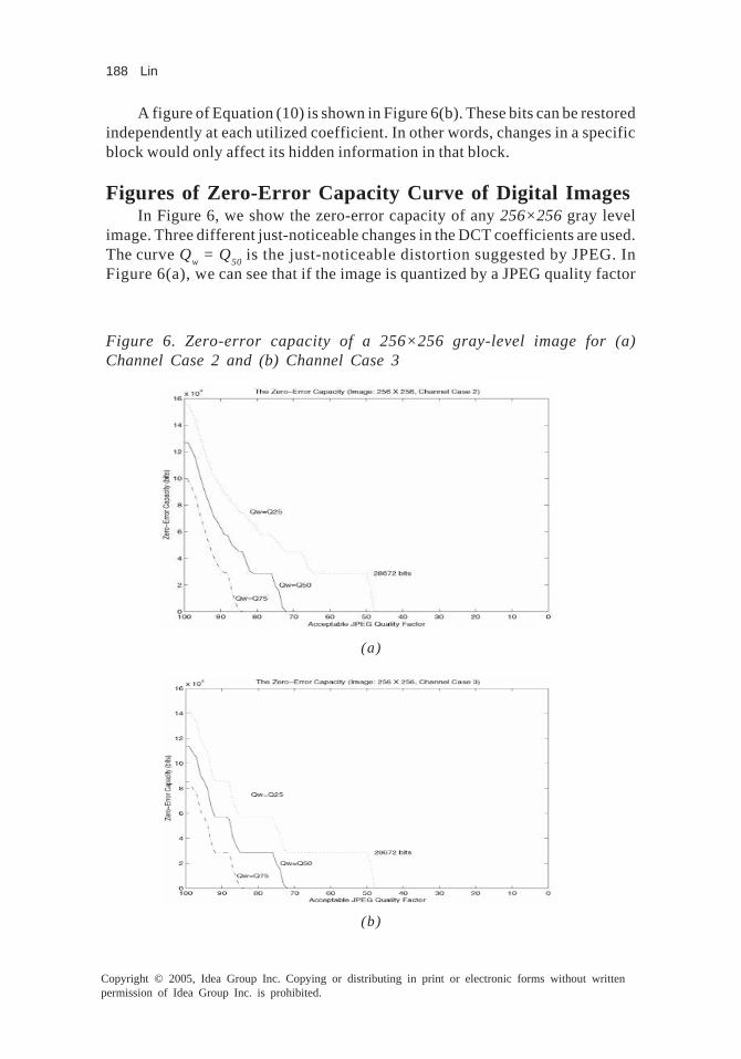
188 Lin
Copyright © 2005, Idea Group Inc. Copying or distributing in print or electronic forms without writtenpermission of Idea Group Inc. is prohibited.
Figure 6. Zero-error capacity of a 256×256 gray-level image for (a)Channel Case 2 and (b) Channel Case 3
(a)
(b)
A figure of Equation (10) is shown in Figure 6(b). These bits can be restoredindependently at each utilized coefficient. In other words, changes in a specificblock would only affect its hidden information in that block.
Figures of Zero-Error Capacity Curve of Digital ImagesIn Figure 6, we show the zero-error capacity of any 256×256 gray level
image. Three different just-noticeable changes in the DCT coefficients are used.The curve Q
w = Q
50 is the just-noticeable distortion suggested by JPEG. In
Figure 6(a), we can see that if the image is quantized by a JPEG quality factor
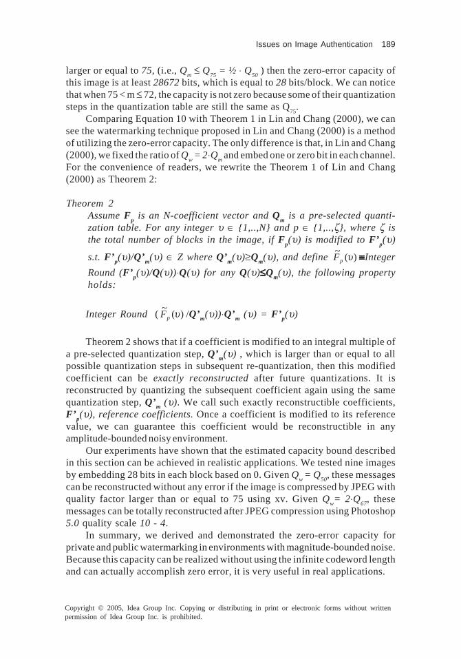
Issues on Image Authentication 189
Copyright © 2005, Idea Group Inc. Copying or distributing in print or electronic forms without writtenpermission of Idea Group Inc. is prohibited.
larger or equal to 75, (i.e., Qm ≤ Q
75 = ½ ⋅ Q
50 ) then the zero-error capacity of
this image is at least 28672 bits, which is equal to 28 bits/block. We can noticethat when 75 < m ≤ 72, the capacity is not zero because some of their quantizationsteps in the quantization table are still the same as Q
75.
Comparing Equation 10 with Theorem 1 in Lin and Chang (2000), we cansee the watermarking technique proposed in Lin and Chang (2000) is a methodof utilizing the zero-error capacity. The only difference is that, in Lin and Chang(2000), we fixed the ratio of Q
w = 2⋅Q
m and embed one or zero bit in each channel.
For the convenience of readers, we rewrite the Theorem 1 of Lin and Chang(2000) as Theorem 2:
Theorem 2Assume F
p is an N-coefficient vector and Q
m is a pre-selected quanti-
zation table. For any integer υ ∈ {1,..,N} and p ∈ {1,..,ζ}, where ζ isthe total number of blocks in the image, if F
p(υ) is modified to F’
p(υ)
s.t. F’p(υ)/Q’m(υ) ∈ Z where Q’m(υ)≥Qm(υ), and define )(~ υpF ≡≡≡≡≡Integer
Round (F’p(υ)/Q(υ))⋅Q(υ) for any Q(υ)≤≤≤≤≤Qm(υ), the following propertyholds:
Integer Round ( )(~ υpF /Q’m(υ))⋅Q’m (υ) = F’p(υ)
Theorem 2 shows that if a coefficient is modified to an integral multiple ofa pre-selected quantization step, Q’m(υ) , which is larger than or equal to allpossible quantization steps in subsequent re-quantization, then this modifiedcoefficient can be exactly reconstructed after future quantizations. It isreconstructed by quantizing the subsequent coefficient again using the samequantization step, Q’m (υ). We call such exactly reconstructible coefficients,F’p(υ), reference coefficients. Once a coefficient is modified to its referencevalue, we can guarantee this coefficient would be reconstructible in anyamplitude-bounded noisy environment.
Our experiments have shown that the estimated capacity bound describedin this section can be achieved in realistic applications. We tested nine imagesby embedding 28 bits in each block based on 0. Given Q
w = Q
50, these messages
can be reconstructed without any error if the image is compressed by JPEG withquality factor larger than or equal to 75 using xv. Given Q
w= 2⋅Q
67, these
messages can be totally reconstructed after JPEG compression using Photoshop5.0 quality scale 10 - 4.
In summary, we derived and demonstrated the zero-error capacity forprivate and public watermarking in environments with magnitude-bounded noise.Because this capacity can be realized without using the infinite codeword lengthand can actually accomplish zero error, it is very useful in real applications.

190 Lin
Copyright © 2005, Idea Group Inc. Copying or distributing in print or electronic forms without writtenpermission of Idea Group Inc. is prohibited.
SELF-AUTHENTICATION-AND-RECOVERYIMAGES
SARI (Self-Authentication-and-Recovery Images, demos and test soft-ware at http://www.ee.columbia.edu/sari) is a semi-fragile watermarking tech-nique that gives “life” to digital images (Lin & Chang, 2001). An example of aSARI system is shown in Figure 7. Like a gecko can recover its cut tail, awatermarked SARI image can detect malicious manipulations (e.g., crop-and-replacement) and approximately recover the original content in the altered area.Another important feature of SARI is its compatibility to JPEG lossy compres-sion within an acceptable quality range. A SARI authenticator can sensitivelydetect malicious changes while accepting alteration introduced by JPEG lossycompression. The lowest acceptable JPEG quality factor depends on an adjust-able watermarking strength controlled in the embedder. SARI images are securebecause the embedded watermarks are dependent on the image content (and ontheir owner’s private key).
Traditional digital signatures, which utilize cryptographic hashing and publickey techniques, have been used to protect the authenticity of traditional data anddocuments (Barni, Barolini, De Rosa, & Piva, 1999). However, such schemesprotect every bit of the data and do not allow any manipulation or processing ofthe data, including acceptable ones such as lossy compression. To the best of ourknowledge, the SARI technique is the only solution that can verify the authen-
o rig in a l im a g e
a d d R D S a n d R ec o ve ry
w a te rm a rk s
m a n ip u la tio n
im a g e a fte r c ro p -an d -re p la c e m e n t an d JP E G lo ssy co m p res s io n
w ate rm a rk e d S A R I im a g e
a u th e n tic a tio n
a u th e n tic a tio n& re co v e ry
o r ig in a l im a g e
a d d R D S a n d R ec o ve ry
w a te rm a rk s
m a n ip u la tio n
im a g e a fte r c ro p -an d -re p la c e m e n t an d JP E G lo ssy co m p res s io n
w ate rm a rk e d S A R I im a g e
a u th e n tic a tio n
a u th e n tic a tio n& re co v e ry
Figure 7. Embedding robust digital signatures to generate self-authentication-and-recovery images
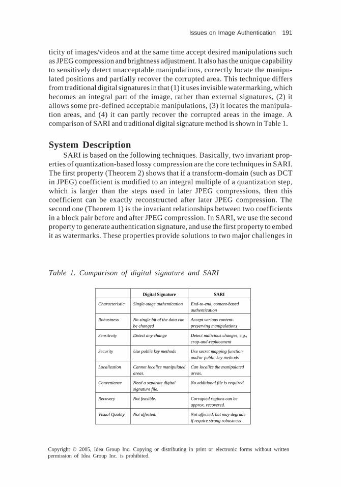
Issues on Image Authentication 191
Copyright © 2005, Idea Group Inc. Copying or distributing in print or electronic forms without writtenpermission of Idea Group Inc. is prohibited.
ticity of images/videos and at the same time accept desired manipulations suchas JPEG compression and brightness adjustment. It also has the unique capabilityto sensitively detect unacceptable manipulations, correctly locate the manipu-lated positions and partially recover the corrupted area. This technique differsfrom traditional digital signatures in that (1) it uses invisible watermarking, whichbecomes an integral part of the image, rather than external signatures, (2) itallows some pre-defined acceptable manipulations, (3) it locates the manipula-tion areas, and (4) it can partly recover the corrupted areas in the image. Acomparison of SARI and traditional digital signature method is shown in Table 1.
System DescriptionSARI is based on the following techniques. Basically, two invariant prop-
erties of quantization-based lossy compression are the core techniques in SARI.The first property (Theorem 2) shows that if a transform-domain (such as DCTin JPEG) coefficient is modified to an integral multiple of a quantization step,which is larger than the steps used in later JPEG compressions, then thiscoefficient can be exactly reconstructed after later JPEG compression. Thesecond one (Theorem 1) is the invariant relationships between two coefficientsin a block pair before and after JPEG compression. In SARI, we use the secondproperty to generate authentication signature, and use the first property to embedit as watermarks. These properties provide solutions to two major challenges in
Digital Signature SARI
Characteristic Single-stage authentication End-to-end, content-based authentication
Robustness No single bit of the data can be changed
Accept various content-preserving manipulations
Sensitivity Detect any change Detect malicious changes, e.g.,
crop-and-replacement
Security Use public key methods Use secret mapping function and/or public key methods
Localization Cannot localize manipulated areas.
Can localize the manipulated areas.
Convenience Need a separate digital
signature file.
No additional file is required.
Recovery Not feasible. Corrupted regions can be approx. recovered.
Visual Quality Not affected. Not affected, but may degrade if require strong robustness
Table 1. Comparison of digital signature and SARI

192 Lin
Copyright © 2005, Idea Group Inc. Copying or distributing in print or electronic forms without writtenpermission of Idea Group Inc. is prohibited.
developing authentication watermarks (aka, integrity watermarks): how toextract short, invariant, and robust information to substitute fragile hash function,and how to embed information that is guaranteed to survive quantization-basedlossy compression to an acceptable extent. In additional to authenticationsignatures, we also embed the recovery bits for recovering approximate pixelvalues in corrupted areas. SARI authenticator utilizes the compressed bitstream,and thus avoids rounding errors in reconstructing transform domain coefficients.
The SARI system was implemented in the Java platform and is currentlyoperational on-line. Users can download the embedder from the SARI websiteand use it to add the semi-fragile watermark into their images. He can thendistribute or publish the watermarked SARI images. The counterpart of theembedder is the authenticator, which can be used in the client side or deployedon a third-party site. Currently, we maintain the authenticator at the samewebsite so that any user can check the authenticity and/or recover originalcontent by uploading the images they received.
The whole space of DCT coefficients is divided into three subspaces:signature generating, watermarking, and ignorable zones. Zones can beoverlapped or non-overlapped. Coefficients in the signature-generating zone areused to generate authentication bits. The watermarking zone is used forembedding signature back to image as watermark. The last zone is negligible.Manipulations of coefficients in this zone do not affect the processes of signaturegeneration and verification. In our system, we use non-overlapping zones togenerate and embed authentication bits. For security, the division method ofzones should be kept secret or be indicated by a secret mapping method using aseed that is time-dependent and/or location-dependent.
A very important issue in implementing this system is to use integer-basedDCT and inverse DCT in all applicable situations. These algorithms control theprecision of the values in both spatial and frequency domains, and thus guaranteeall 8-bit integer values in the spatial domain will be exactly the same as theiroriginal values even after DCT and inverse DCT. Using integer-based opera-tions is a critical reason why our implementation of the SARI system can achieveno false alarm and high manipulation detection probability. Details of the SARIsystem are shown in Lin (2000).
Figure 8(a) shows the user interface of the embedder in which the user canopen image files in various formats, adjust the acceptable compression level,embed the watermarks, check the quality of the watermarked images and savethem to files in desired formats (compressed or uncompressed). The userinterface of the authenticator includes the functions that open image files invarious formats, automatically examine the existence of the SARI watermark,and authenticate and recover the manipulated areas.

Issues on Image Authentication 193
Copyright © 2005, Idea Group Inc. Copying or distributing in print or electronic forms without writtenpermission of Idea Group Inc. is prohibited.
Example and ExperimentsFigure 9 and 10 show an example of using SARI. In Figure 9, we first embed
watermarks in the image, and then use Photoshop 5.0 to manipulate it and saveit as a JPEG file. Figure 10 shows the authentication result of such manipulations.We can clearly see that the manipulated areas can be located by the SARIauthenticator. In Figure 10(b), we can see that the corrupted area has beenrecovered.
We also conducted subjective tests to examine the quality of watermarkedimage toward human observers. Four viewers are used for this test. Theirbackground and monitor types are listed in Table 2. We use the average ofsubjective tests to show the maximum embedding strength for each image. Thisis shown in Table 3. From this table, we can see the number of bits embedded
(a) (b)
Figure 8. (a) User interface of the SARI embedder, (b) Example of thewatermarked SARI image (size: 256x384, PSNR = 41.25 dB, embeddedsemi-fragile info bits: 20727)
Figure 9. (a) Original image after adding SARI watermark, (b) Manipulatedimage by crop-and-replacement and JPEG lossy compression
(a) (b)
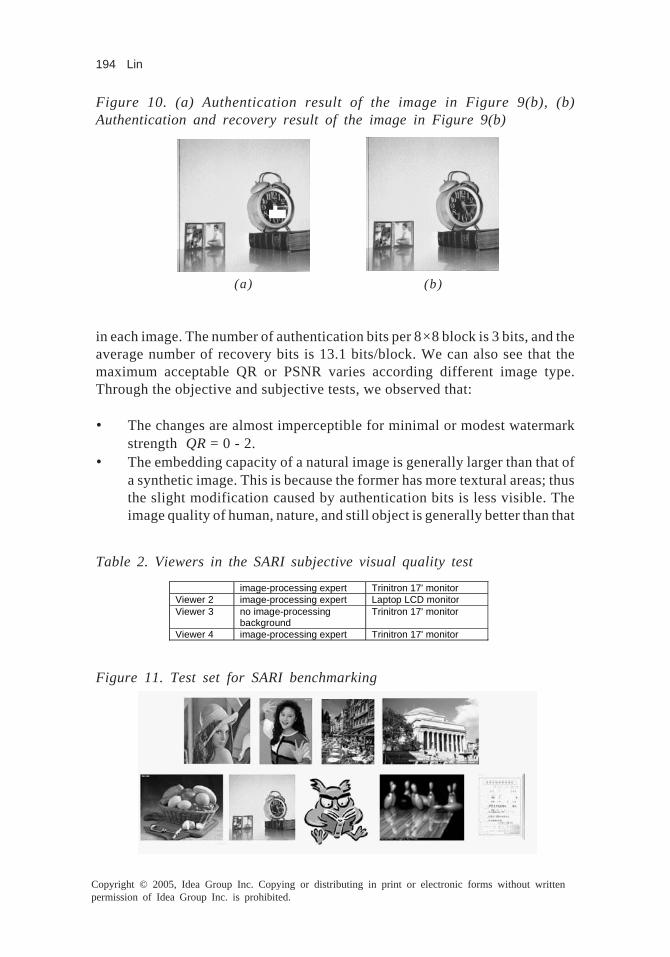
194 Lin
Copyright © 2005, Idea Group Inc. Copying or distributing in print or electronic forms without writtenpermission of Idea Group Inc. is prohibited.
in each image. The number of authentication bits per 8×8 block is 3 bits, and theaverage number of recovery bits is 13.1 bits/block. We can also see that themaximum acceptable QR or PSNR varies according different image type.Through the objective and subjective tests, we observed that:
• The changes are almost imperceptible for minimal or modest watermarkstrength QR = 0 - 2.
• The embedding capacity of a natural image is generally larger than that ofa synthetic image. This is because the former has more textural areas; thusthe slight modification caused by authentication bits is less visible. Theimage quality of human, nature, and still object is generally better than that
(a) (b)
Figure 10. (a) Authentication result of the image in Figure 9(b), (b)Authentication and recovery result of the image in Figure 9(b)
image-processing expert Trinitron 17' monitor Viewer 2 image-processing expert Laptop LCD monitor Viewer 3 no image-processing
background Trinitron 17' monitor
Viewer 4 image-processing expert Trinitron 17' monitor
Table 2. Viewers in the SARI subjective visual quality test
Figure 11. Test set for SARI benchmarking
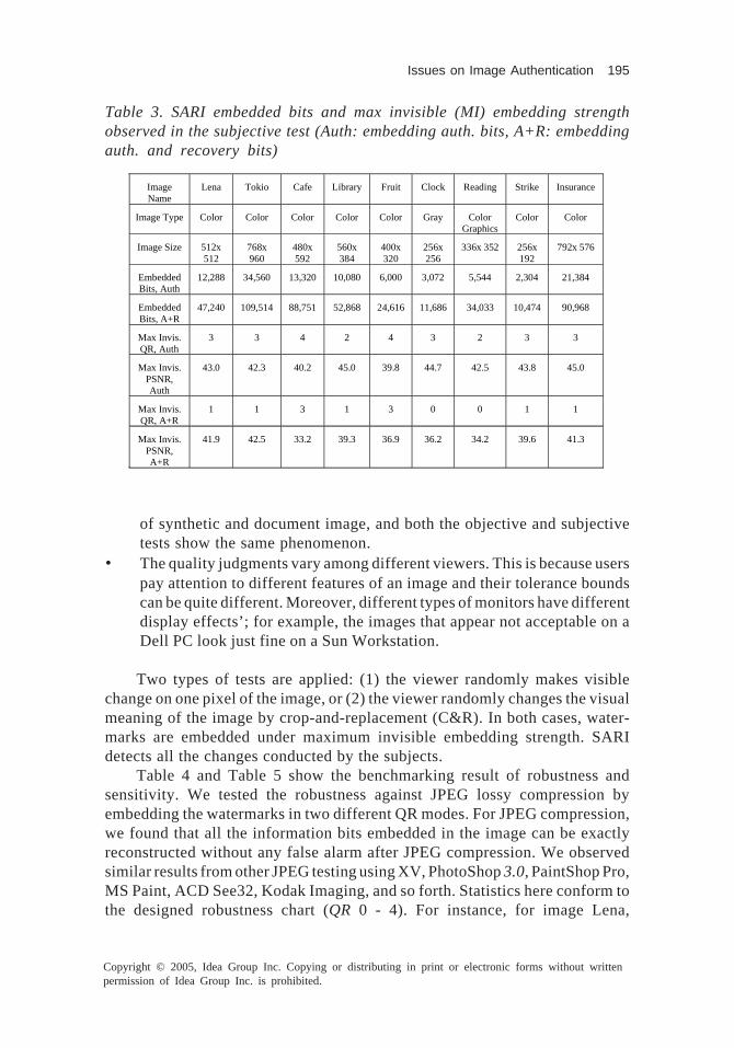
Issues on Image Authentication 195
Copyright © 2005, Idea Group Inc. Copying or distributing in print or electronic forms without writtenpermission of Idea Group Inc. is prohibited.
of synthetic and document image, and both the objective and subjectivetests show the same phenomenon.
• The quality judgments vary among different viewers. This is because userspay attention to different features of an image and their tolerance boundscan be quite different. Moreover, different types of monitors have differentdisplay effects’; for example, the images that appear not acceptable on aDell PC look just fine on a Sun Workstation.
Two types of tests are applied: (1) the viewer randomly makes visiblechange on one pixel of the image, or (2) the viewer randomly changes the visualmeaning of the image by crop-and-replacement (C&R). In both cases, water-marks are embedded under maximum invisible embedding strength. SARIdetects all the changes conducted by the subjects.
Table 4 and Table 5 show the benchmarking result of robustness andsensitivity. We tested the robustness against JPEG lossy compression byembedding the watermarks in two different QR modes. For JPEG compression,we found that all the information bits embedded in the image can be exactlyreconstructed without any false alarm after JPEG compression. We observedsimilar results from other JPEG testing using XV, PhotoShop 3.0, PaintShop Pro,MS Paint, ACD See32, Kodak Imaging, and so forth. Statistics here conform tothe designed robustness chart (QR 0 - 4). For instance, for image Lena,
Image Name
Lena Tokio Cafe Library Fruit Clock Reading Strike Insurance
Image Type Color Color Color Color Color Gray Color Graphics
Color Color
Image Size 512x 512
768x 960
480x 592
560x 384
400x 320
256x 256
336x 352 256x 192
792x 576
Embedded Bits, Auth
12,288 34,560 13,320 10,080 6,000 3,072 5,544 2,304 21,384
Embedded Bits, A+R
47,240 109,514 88,751 52,868 24,616 11,686 34,033 10,474 90,968
Max Invis. QR, Auth
3 3 4 2 4 3 2 3 3
Max Invis. PSNR, Auth
43.0 42.3 40.2 45.0 39.8 44.7 42.5 43.8 45.0
Max Invis. QR, A+R
1 1 3 1 3 0 0 1 1
Max Invis. PSNR, A+R
41.9 42.5 33.2 39.3 36.9 36.2 34.2 39.6 41.3
Table 3. SARI embedded bits and max invisible (MI) embedding strengthobserved in the subjective test (Auth: embedding auth. bits, A+R: embeddingauth. and recovery bits)

196 Lin
Copyright © 2005, Idea Group Inc. Copying or distributing in print or electronic forms without writtenpermission of Idea Group Inc. is prohibited.
watermark with strength QR = 4 survives Photoshop 5.0 Quality Factor 1 - 10.Watermarks embedded by using maximum invisible subjective embeddingstrength (MED) can survive JPEG compression Quality Factor 3 - 10. This resultis even better than predicted. We embedded the watermarks in the QR = 4 modeto test its sensitivity to malicious manipulations. QR = 4 is the most robust modeto compression and is the least sensitive mode in detecting manipulations3. Wefound that even in this worst case, SARI authenticator is quite sensitive tomalicious manipulation. It is very effective in detecting crop-and-replacementmanipulations up to one-pixel value changes. During the test, each subjectrandomly selected a pixel and changed its RGB value. The subject was told toarbitrarily change the values as long as the changes are visible. Each subjecttested three times on each benchmark image. After the change is made, thesubjects apply the SARI detectors to test whether the changes can be detected.The result in Table 5 shows that SARI detectors can detect all of them.
In our second test, the subjects manually use Photoshop to manipulate theimage by the crop-and-replacement process. They can arbitrarily choose therange of manipulation up to half of the image. Results also show that SARIauthenticator successfully identified these changes. For recovery tests, we
Image Name Lena Tokio Cafe Library Fruit Clock Reading Strike Insurance Survive QF, MED
3 3 3 4 1 4 3 3 4
Survive QF, QR
4 1 2 2 1 2 2 2 2
Table 4. SARI robustness performance on JPEG compression measured bythe quality factor in Photoshop 5.0 (Two kinds of embedding strength areapplied: (1) MED: maximum invisible embedding strength, which is avariant SARI quality-and-recovery setting parameter based on subjectivetest results, and (2) A fixed SARI quality and recovery (QR) setting = 4)
Image Name Lena Tokio Cafe Library Fruit Clock Reading Strike Insurance Detect M., 1-pix
Y Y Y Y Y Y Y Y Y
Detect M., C\&R
Y Y Y Y Y Y Y Y Y
Table 5. SARI sensitivity test under the maximum subjective embeddingstrength (Two types of test are applied: (1) the viewer randomly makesvisible change on a pixel of the image, (2) the viewer randomly changes thevisual meaning of the image by crop-and-replacement (C&R). In bothcases, watermarks are embedded under maximum invisible embeddingstrength. SARI detects all the changes conducted by the subjects. )

Issues on Image Authentication 197
Copyright © 2005, Idea Group Inc. Copying or distributing in print or electronic forms without writtenpermission of Idea Group Inc. is prohibited.
found that in all malicious manipulation cases, an approximation of the originalpixels in the corrupted area can be properly reconstructed.
We also tested other image processing manipulations. The authenticatordetects changes resulted by blurring and median filtering. For Gaussian noises,the authenticator detected those changes. But, if further compressed by JPEG,usually no changes were detected because compression cancelled out the slightchanges introduced by it. We also found that the robustness of noises or filteringcan be increased through setting larger tolerance bound in the authenticationprocess. Namely, rather than checking the coefficient relationships described inTheorem 2, the authenticator allows for a minor change of the coefficientdifference up to some tolerance level. Examples of using tolerance bounds arein Lin and Chang (2001).
This technology could help multimedia data to regain their trustworthiness.Hopefully we can say “seeing is believing” again in this digital era!!
SEMANTIC AUTHENTICATION SYSTEM In this section, we first describe the proposed system structure for
multimedia semantic authentication, followed by the details and the experimentalresults.
A multimedia semantic authentication system architecture overview isshown in Figure 12. The system includes two parts: a watermark embedder andan authenticator. In the watermark embedding process, our objective is to embeda watermark, which includes the information of the models, such as objects, thatare included in a video clip or image. We use either the automatic segmentationand classification result (the solid line in Figure 12) or the manual/semi-automaticannotation (the dotted line in Figure 12) to decide what the objects are. For thefirst scenario, the classifier learns the knowledge of objects using statisticallearning, which needs training from the previous annotated video clips. We builta video annotation tool, VideoAnnEx, for the task of associating labels to thevideo shots on the region levelLin and Tseng (n.d.). VideoAnnEx uses threekinds of labels: background scene, foreground object, and events in the lexicon.This lexicon can be pre-defined or added to VideoAnnEx by the annotator.Based on the annotation result of a large video corpus, we can build models foreach of the labels, for example, sky, or bird. After the models are built, theclassifier will be able to recognize the objects in a video clip based on the resultof visual object segmentation and feature extraction.
Because the capability of classifier is limited to the models that werepreviously built, the second scenario — manual annotation of unrecognizedobjects — is sometimes necessary for classifier retraining. The classifier canlearn new models or modify existing models if there is annotation associated with
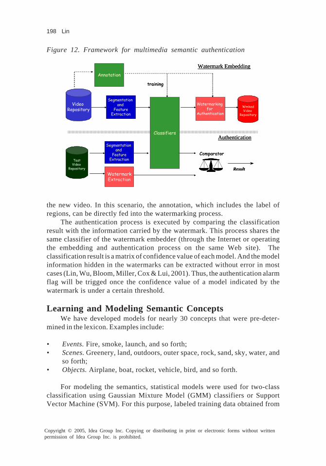
198 Lin
Copyright © 2005, Idea Group Inc. Copying or distributing in print or electronic forms without writtenpermission of Idea Group Inc. is prohibited.
the new video. In this scenario, the annotation, which includes the label ofregions, can be directly fed into the watermarking process.
The authentication process is executed by comparing the classificationresult with the information carried by the watermark. This process shares thesame classifier of the watermark embedder (through the Internet or operatingthe embedding and authentication process on the same Web site). Theclassification result is a matrix of confidence value of each model. And the modelinformation hidden in the watermarks can be extracted without error in mostcases (Lin, Wu, Bloom, Miller, Cox & Lui, 2001). Thus, the authentication alarmflag will be trigged once the confidence value of a model indicated by thewatermark is under a certain threshold.
Learning and Modeling Semantic ConceptsWe have developed models for nearly 30 concepts that were pre-deter-
mined in the lexicon. Examples include:
• Events. Fire, smoke, launch, and so forth;• Scenes. Greenery, land, outdoors, outer space, rock, sand, sky, water, and
so forth;• Objects. Airplane, boat, rocket, vehicle, bird, and so forth.
For modeling the semantics, statistical models were used for two-classclassification using Gaussian Mixture Model (GMM) classifiers or SupportVector Machine (SVM). For this purpose, labeled training data obtained from
�����������
������
���������������
������
����������������
�����������
��������������
����������������
Watermark Embedding
Authentication
����� �����
����������
���� �����
����������
��������������
����������������
������������������
����������
Result
�����������
������
���������������
������
����������������
�����������
��������������
����������������
Watermark Embedding
Authentication
����� �����
����������
���� �����
����������
��������������
����������������
������������������
����������
Result
Figure 12. Framework for multimedia semantic authentication
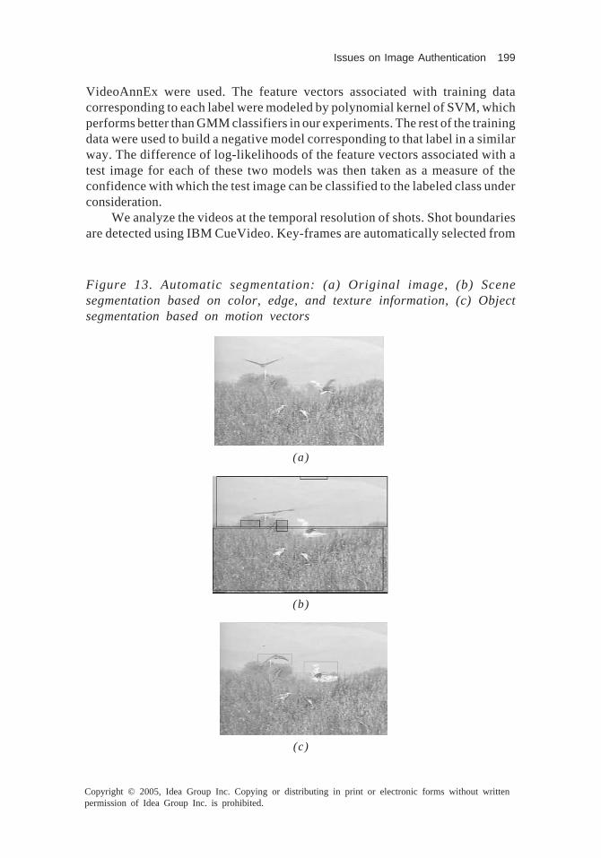
Issues on Image Authentication 199
Copyright © 2005, Idea Group Inc. Copying or distributing in print or electronic forms without writtenpermission of Idea Group Inc. is prohibited.
VideoAnnEx were used. The feature vectors associated with training datacorresponding to each label were modeled by polynomial kernel of SVM, whichperforms better than GMM classifiers in our experiments. The rest of the trainingdata were used to build a negative model corresponding to that label in a similarway. The difference of log-likelihoods of the feature vectors associated with atest image for each of these two models was then taken as a measure of theconfidence with which the test image can be classified to the labeled class underconsideration.
We analyze the videos at the temporal resolution of shots. Shot boundariesare detected using IBM CueVideo. Key-frames are automatically selected from
(a)
(b)
(c)
Figure 13. Automatic segmentation: (a) Original image, (b) Scenesegmentation based on color, edge, and texture information, (c) Objectsegmentation based on motion vectors
200 Lin
Copyright © 2005, Idea Group Inc. Copying or distributing in print or electronic forms without writtenpermission of Idea Group Inc. is prohibited.
each shot. From each key-frame we extract features representing color, texture,structure, and shape. Color is represented by 24-dimensional linearized HSVhistograms and color moments. Structure is captured by computing edgedirection histograms. Texture is captured by gray-level co-occurrence matrixproperties. Shape is captured using Dudani’s moment invariants (Dudani,Breeding, & McGhee, 1977).
SegmentationWe built a sub real-time automatic segmentation for visual object segmen-
tation. It can segment the visual object for every I- and P- frames in real time.To segment a background scene object, we use a block-based region growingmethod on each decoded I- or P- frame in the video clip. The criteria of regiongrowing are based on the color histogram, edge histogram, and Tamura’s texturedirectionality index (Tamura, Mori, & Yamawaki, 1978) of the block.
To find out the foreground object, we calculate the motion vectors of I- andP- frames, and use them to determine objects with region growing in the spatialdomain and additional tracking constraints in the time domain. We tried to use theMPEG motion vectors in our system. However, those motion vectors were toonoisy to be useful in our experiments. Therefore, our system calculates themotion vectors using a spiral searching technique, which can be calculated in realtime if only I- and P- frames are used. Through our experiments, we find out acombination of the motion vectors with the color, edge, and texture informationusually does not generate good results for foreground object segmentation.Therefore, only motion information is used.
Note that it is very difficult to segment foreground object if only an image,not a video clip, is available. Therefore, for images, only background sceneobjects can be reliably segmented. Thus, in our semantic authentication system,we can allow users to draw the regions corresponding to foreground objects inboth the watermark embedding and authentication processes to enhance thesystem performance.
WatermarkingWe embed the classification result of the models into the original image. A
rotation, scaling, and shifting invariant watermarking method proposed in Lin,Wu, Bloom, Miller, Cox and Lui (2001) is used. The basic idea of this algorithmis using a shaping algorithm to modify a feature vector, which is a projection oflog-polar map of Fourier magnitudes (a.k.a. the Fourier-Mellin Transform, FMT)of images along the log-radius axis. As shown in Figure 14, the blue signal is theoriginal feature vector, whose distribution is similar to a Gaussian noise. Ourobjective is to modify the feature vector to make it closer to the pre-definedwatermark signal (red). Because the FMT and inverse FMT are not one-to-onemapping, we cannot directly change the FM coefficients and apply inverse FMT

Issues on Image Authentication 201
Copyright © 2005, Idea Group Inc. Copying or distributing in print or electronic forms without writtenpermission of Idea Group Inc. is prohibited.
to get the watermarked DFT coefficients. We can only modify coefficients in theDFT domain to make the modified feature vector to be close to the watermarkvector. This process is iterated for about three to five times. Then, the finalmodified feature vector (aka, mixed signal) would be similar to the watermarkvector. Feature vector shaping works better than the traditional spread spectrumwatermarking method on the absence of original signal in watermarking retrieval(i.e., public watermarking). In the traditional spread spectrum method:
T( Sw ) = T( S ) + X
where T( . ) is a specific transform (e.g., DCT) defined by system, S is the sourcesignal, X is the watermark signal, and T( Sw ) is the watermarked signal. Theextraction of watermark is based on a correlation value of T( Sw ) and X. Whilein feature vector shaping, T( Sw ) is approximately equal to X:
T( Sw ) ≈ X
Comparing these two equations, we can see that the original signal has farless effect in the correlation value using the feature vector shaping. Thus, thismethod (or called mixed signal) performs better in public watermarking cases(Lin, Wu, Bloom, Miller, Cox, & Lui, 2001).
Figure 14. Example of watermarking based on feature vector shaping: Linewith points that do not reach as high — Original feature vector; Line withflat tops — Watermark vector; Line with highest points — Modified featuredvector (mixed signal)

202 Lin
Copyright © 2005, Idea Group Inc. Copying or distributing in print or electronic forms without writtenpermission of Idea Group Inc. is prohibited.
Experimental Results We have annotated on the 14 hours of video clips from the TREC video
retrieval benchmarking 2001 corpus. These video clips include 5,783 shots. Thelexicon is shown in Lin and Tseng (n.d.). This corpus includes mostly commen-tary videos of various natural, scientific, and indoor scenarios. We built nearly30 models based on the annotated lexicon. Each model is assigned an ID, whichcan be as long as 42-bits watermark vectors (Lin, Wu, Bloom, Miller, Cox, & Lui,2001).
Some preliminary experiments have been done to test the efficiency of thesystem. First, we test the precision of the classification result when the video isnot manipulated. If we use the automatic bounding boxes for classification, theprecision of classification result is 72.1%. This precision number can beincreased to 98.3%, if the users indicate the regions of objects in the authenti-cation process and watermark embedding process. In this case, because similarmanual annotated regions are used for the training and testing process, the SVMclassifier can achieve very high precision accuracy (Burges, 1998).
In another experiment, we extract the key-frames of shots and recompressthem using a JPEG compression quality factor of 50. We then get a 98.1% ofprecision when the same manual bounding boxes are used, and 69.2% ofauthentication precision when automatic segmentation is applied. This experi-ment shows the classification may be affected by lossy compression. Thedegradation of system performance is basically affected by the segmentationalgorithm. In both cases, the model information hidden in the watermarks can beextracted without any error.
We proposed a novel watermarking system for image/video semanticauthentication. Our preliminary experiments show the promising effectivenessof this method. In this section, we did not address the security issues, which willbe a primary direction in our future research. We will investigate on thesegmentation, learning and statistical classification algorithms to improve thesystem precision rates on classification. And we will also conduct moreexperiments to test the system performance under various situations.
CONCLUSIONSA new economy based on information technology has emerged. People
create, sell, and interact with multimedia content. The Internet provides aubiquitous infrastructure for e-commerce; however, it does not provide enoughprotection for its participants. Lacking adequate protection mechanisms, contentproviders are reluctant to distribute their digital content, because it can be easilyre-distributed. Content receivers are skeptical about the source and integrity ofcontent. Current technology in network security protects content during one
Issues on Image Authentication 203
Copyright © 2005, Idea Group Inc. Copying or distributing in print or electronic forms without writtenpermission of Idea Group Inc. is prohibited.
stage of transmission. But, it cannot protect multimedia data through multiplestages of transmission, involving both people and machines. These concernshave hindered the universal acceptance of digital multimedia. At the same time,they also stimulate a new research field: multimedia security.
In this chapter, we described a robust digital signature algorithm and a semi-fragile watermarking algorithm. These algorithms help design the Self-Authen-tication-and-Recovery Images (SARI) system, demonstrating unique authenti-cation capacities missing in existing systems. SARI is a semi-fragile watermarkingtechnique that gives “life” to digital images. Like a gecko can recover its cut tail,a watermarked SARI image can detect malicious crop-and-replacement ma-nipulations and recover an approximated original image in the altered area.Another important feature of SARI is its compatibility to JPEG lossy compres-sion. SARI authenticator is the only system that can sensitively detect maliciouschanges while accepting alteration introduced by JPEG lossy compression. Thelowest acceptable JPEG quality factor depends on an adjustable watermarkingstrength controlled in the embedder. SARI images are secure because theembedded watermarks are dependent on their own content (and on theirowner).
There are many more topics waiting to be solved in the field of multimediasecurity. In the area of multimedia authentication, open issues include:
• Document Authentication. Documents include combinations of text,pictures, and graphics. This task may include two directions: authenticationof digital documents after they are printed-and-scanned, and authenticationof paper documents after they are scanned-and-printed or photocopied.The first direction is to develop watermarking or digital signature tech-niques for the continuous-tone images, color graphs, and text. The seconddirection is to develop half-toning techniques that can hide information inthe bi-level half-tone document representations.
• Audio Authentication. The idea here is to study the state-of-the-artspeech and speaker recognition techniques, and to embed the speaker (orhis/her vocal characteristics) and speech content in the audio signal. Thisresearch also includes the development of audio watermarking techniquessurviving lossy compression.
• Image/Video/Graph Authentication. The idea is to focus on developingauthentication techniques to accept new compression standards (such asJPEG-2000) and general image/video processing operations, and rejectmalicious manipulations. In some cases, blind authentication schemes thatdirectly analyze the homogeneous properties of multimedia data itself,without any prior digital signature or watermarks, are desired in severalapplications.
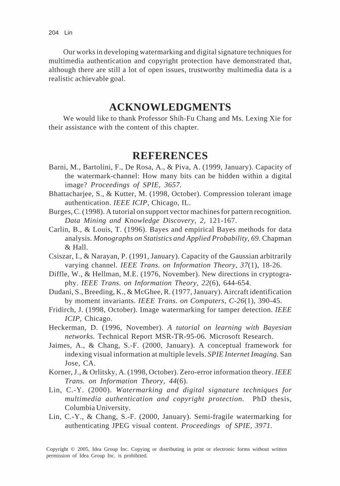
204 Lin
Copyright © 2005, Idea Group Inc. Copying or distributing in print or electronic forms without writtenpermission of Idea Group Inc. is prohibited.
Our works in developing watermarking and digital signature techniques formultimedia authentication and copyright protection have demonstrated that,although there are still a lot of open issues, trustworthy multimedia data is arealistic achievable goal.
ACKNOWLEDGMENTSWe would like to thank Professor Shih-Fu Chang and Ms. Lexing Xie for
their assistance with the content of this chapter.
REFERENCESBarni, M., Bartolini, F., De Rosa, A., & Piva, A. (1999, January). Capacity of
the watermark-channel: How many bits can be hidden within a digitalimage? Proceedings of SPIE, 3657.
Bhattacharjee, S., & Kutter, M. (1998, October). Compression tolerant imageauthentication. IEEE ICIP, Chicago, IL.
Burges, C. (1998). A tutorial on support vector machines for pattern recognition.Data Mining and Knowledge Discovery, 2, 121-167.
Carlin, B., & Louis, T. (1996). Bayes and empirical Bayes methods for dataanalysis. Monographs on Statistics and Applied Probability, 69. Chapman& Hall.
Csiszar, I., & Narayan, P. (1991, January). Capacity of the Gaussian arbitrarilyvarying channel. IEEE Trans. on Information Theory, 37(1), 18-26.
Diffle, W., & Hellman, M.E. (1976, November). New directions in cryptogra-phy. IEEE Trans. on Information Theory, 22(6), 644-654.
Dudani, S., Breeding, K., & McGhee, R. (1977, January). Aircraft identificationby moment invariants. IEEE Trans. on Computers, C-26(1), 390-45.
Fridirch, J. (1998, October). Image watermarking for tamper detection. IEEEICIP, Chicago.
Heckerman, D. (1996, November). A tutorial on learning with Bayesiannetworks. Technical Report MSR-TR-95-06. Microsoft Research.
Jaimes, A., & Chang, S.-F. (2000, January). A conceptual framework forindexing visual information at multiple levels. SPIE Internet Imaging. SanJose, CA.
Korner, J., & Orlitsky, A. (1998, October). Zero-error information theory. IEEETrans. on Information Theory, 44(6).
Lin, C.-Y. (2000). Watermarking and digital signature techniques formultimedia authentication and copyright protection. PhD thesis,Columbia University.
Lin, C.-Y., & Chang, S.-F. (2000, January). Semi-fragile watermarking forauthenticating JPEG visual content. Proceedings of SPIE, 3971.
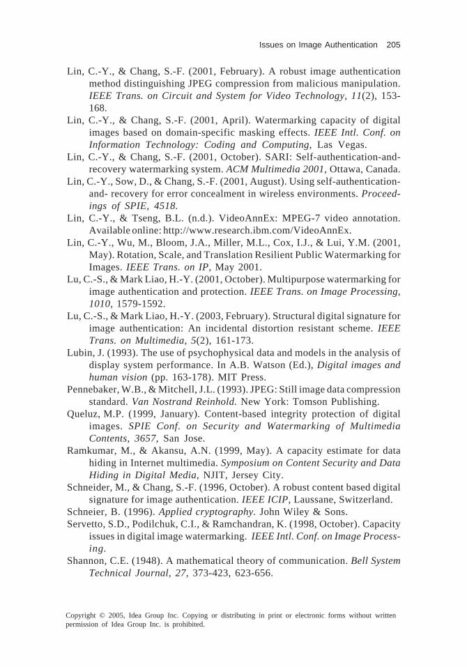
Issues on Image Authentication 205
Copyright © 2005, Idea Group Inc. Copying or distributing in print or electronic forms without writtenpermission of Idea Group Inc. is prohibited.
Lin, C.-Y., & Chang, S.-F. (2001, February). A robust image authenticationmethod distinguishing JPEG compression from malicious manipulation.IEEE Trans. on Circuit and System for Video Technology, 11(2), 153-168.
Lin, C.-Y., & Chang, S.-F. (2001, April). Watermarking capacity of digitalimages based on domain-specific masking effects. IEEE Intl. Conf. onInformation Technology: Coding and Computing, Las Vegas.
Lin, C.-Y., & Chang, S.-F. (2001, October). SARI: Self-authentication-and-recovery watermarking system. ACM Multimedia 2001, Ottawa, Canada.
Lin, C.-Y., Sow, D., & Chang, S.-F. (2001, August). Using self-authentication-and- recovery for error concealment in wireless environments. Proceed-ings of SPIE, 4518.
Lin, C.-Y., & Tseng, B.L. (n.d.). VideoAnnEx: MPEG-7 video annotation.Available online: http://www.research.ibm.com/VideoAnnEx.
Lin, C.-Y., Wu, M., Bloom, J.A., Miller, M.L., Cox, I.J., & Lui, Y.M. (2001,May). Rotation, Scale, and Translation Resilient Public Watermarking forImages. IEEE Trans. on IP, May 2001.
Lu, C.-S., & Mark Liao, H.-Y. (2001, October). Multipurpose watermarking forimage authentication and protection. IEEE Trans. on Image Processing,1010, 1579-1592.
Lu, C.-S., & Mark Liao, H.-Y. (2003, February). Structural digital signature forimage authentication: An incidental distortion resistant scheme. IEEETrans. on Multimedia, 5(2), 161-173.
Lubin, J. (1993). The use of psychophysical data and models in the analysis ofdisplay system performance. In A.B. Watson (Ed.), Digital images andhuman vision (pp. 163-178). MIT Press.
Pennebaker, W.B., & Mitchell, J.L. (1993). JPEG: Still image data compressionstandard. Van Nostrand Reinhold. New York: Tomson Publishing.
Queluz, M.P. (1999, January). Content-based integrity protection of digitalimages. SPIE Conf. on Security and Watermarking of MultimediaContents, 3657, San Jose.
Ramkumar, M., & Akansu, A.N. (1999, May). A capacity estimate for datahiding in Internet multimedia. Symposium on Content Security and DataHiding in Digital Media, NJIT, Jersey City.
Schneider, M., & Chang, S.-F. (1996, October). A robust content based digitalsignature for image authentication. IEEE ICIP, Laussane, Switzerland.
Schneier, B. (1996). Applied cryptography. John Wiley & Sons.Servetto, S.D., Podilchuk, C.I., & Ramchandran, K. (1998, October). Capacity
issues in digital image watermarking. IEEE Intl. Conf. on Image Process-ing.
Shannon, C.E. (1948). A mathematical theory of communication. Bell SystemTechnical Journal, 27, 373-423, 623-656.

206 Lin
Copyright © 2005, Idea Group Inc. Copying or distributing in print or electronic forms without writtenpermission of Idea Group Inc. is prohibited.
Shannon, C.E. (1956). The zero-error capacity of a noisy channel. IRE Trans.on Information Theory, IT-2, 8-19.
Tamura, H., Mori, S., & Yamawaki, T. (1978). Texture features correspondingto visual perception. IEEE Trans. on Sys. Man., and Cybemetics, 8(6).
Watson, A.B. (1993). DCT quantization matrices visually optimized for indi-vidual images. Proceeding of SPIE, 1913, 202-216.
ENDNOTES1 Note that Q
w can be assumed to be uniform in all coefficients in the same
DCT frequency position, or they can be non-uniform if we adopt somehuman perceptual properties. For Case 2, we assume the uniform property,while whether Q
w is uniform or non-uniform does not affect our discussion
in Case 3.2 Some application software may discard all the 29th .. 64th DCT coefficients
regardless of their magnitudes.3 We use QR = 2 for the Insurance image because the visual degradation of
QR = 4 is clearly visible.

Digital Signature-Based Image Authentication 207
Copyright © 2005, Idea Group Inc. Copying or distributing in print or electronic forms without writtenpermission of Idea Group Inc. is prohibited.
Chapter VII
Digital Signature-BasedImage AuthenticationDer-Chyuan Lou, National Defense University, Taiwan
Jiang-Lung Liu, National Defense University, Taiwan
Chang-Tsun Li, University of Warwick, UK
ABSTRACTThis chapter is intended to disseminate the concept of digital signature-based image authentication. Capabilities of digital signature-based imageauthentication and its superiority over watermarking-based approachesare described first. Subsequently, general models of this technique — strictauthentication and non-strict authentication are introduced. Specificschemes of the two general models are also reviewed and compared.Finally, based on the review, design issues faced by the researchers anddevelopers are outlined.
INTRODUCTIONIn the past decades, the technological advances of international communi-
cation networks have facilitated efficient digital image exchanges. However, theavailability of versatile digital signal/image processing tools has also made imageduplication trivial and manipulations discernable for the human visual system(HVS). Therefore, image authentication and integrity verification have becomea popular research area in recent years. Generally, image authentication isprojected as a procedure of guaranteeing that the image content has not been
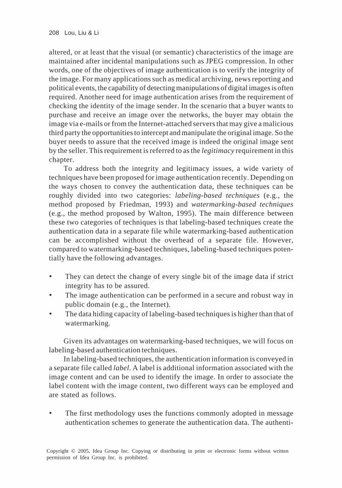
208 Lou, Liu & Li
Copyright © 2005, Idea Group Inc. Copying or distributing in print or electronic forms without writtenpermission of Idea Group Inc. is prohibited.
altered, or at least that the visual (or semantic) characteristics of the image aremaintained after incidental manipulations such as JPEG compression. In otherwords, one of the objectives of image authentication is to verify the integrity ofthe image. For many applications such as medical archiving, news reporting andpolitical events, the capability of detecting manipulations of digital images is oftenrequired. Another need for image authentication arises from the requirement ofchecking the identity of the image sender. In the scenario that a buyer wants topurchase and receive an image over the networks, the buyer may obtain theimage via e-mails or from the Internet-attached servers that may give a maliciousthird party the opportunities to intercept and manipulate the original image. So thebuyer needs to assure that the received image is indeed the original image sentby the seller. This requirement is referred to as the legitimacy requirement in thischapter.
To address both the integrity and legitimacy issues, a wide variety oftechniques have been proposed for image authentication recently. Depending onthe ways chosen to convey the authentication data, these techniques can beroughly divided into two categories: labeling-based techniques (e.g., themethod proposed by Friedman, 1993) and watermarking-based techniques(e.g., the method proposed by Walton, 1995). The main difference betweenthese two categories of techniques is that labeling-based techniques create theauthentication data in a separate file while watermarking-based authenticationcan be accomplished without the overhead of a separate file. However,compared to watermarking-based techniques, labeling-based techniques poten-tially have the following advantages.
• They can detect the change of every single bit of the image data if strictintegrity has to be assured.
• The image authentication can be performed in a secure and robust way inpublic domain (e.g., the Internet).
• The data hiding capacity of labeling-based techniques is higher than that ofwatermarking.
Given its advantages on watermarking-based techniques, we will focus onlabeling-based authentication techniques.
In labeling-based techniques, the authentication information is conveyed ina separate file called label. A label is additional information associated with theimage content and can be used to identify the image. In order to associate thelabel content with the image content, two different ways can be employed andare stated as follows.
• The first methodology uses the functions commonly adopted in messageauthentication schemes to generate the authentication data. The authenti-

Digital Signature-Based Image Authentication 209
Copyright © 2005, Idea Group Inc. Copying or distributing in print or electronic forms without writtenpermission of Idea Group Inc. is prohibited.
cation data are then encrypted with secret keys or private keys dependingon what cryptographic authentication protocol is employed. When applyingto two different bit-streams (i.e., different authentication data), thesefunctions can produce two different bit sequences, in such a way that thechange of every single bit of authentication data can be detected. In thischapter, image authentication schemes of this class are referred to as strictauthentication.
• The second methodology uses some special-purpose functions to extractessential image characteristics (or features) and encrypt them withsenders’ private keys (Li, Lou & Chen, 2000; Li, Lou & Liu, 2003). Thisprocedure is the same as the digital signature protocol except that thefeatures must be designed to compromise with some specific imageprocessing techniques such as JPEG compression (Wallace, 1991). In thischapter, image authentication techniques of this class are referred to asnon-strict authentication.
The strict authentication approaches should be used when strict imageintegrity is required and no modification is allowed. The functions used toproduce such authentication data (or authenticators) can be grouped into threeclasses: message encryption, message authentication code (MAC), and hashfunction (Stallings, 2002). For message encryption, the original message isencrypted. The encrypted result (or cipher-text) of the entire message serves asits authenticator. To authenticate the content of an image, both the sender andreceiver share the same secret key. Message authentication code is a fixed-length value (authenticator) that is generated by a public function with a secretkey. The sender and receiver also share the same secret key that is used togenerate the authenticator. A hash function is a public function that maps amessage of any length to a fixed-length hash value that serves as the authenti-cator. Because there is no secret key adopted in creating an authenticator, thehash functions have to be included in the procedure of digital signature for theelectronic exchange of message. The details of how to perform those labeling-based authentication schemes and how to obtain the authentication data aredescribed in the second section.
The non-strict authentication approaches must be chosen when some formsof image modifications (e.g., JPEG lossy compression) are permitted, whilemalicious manipulation (e.g., objects’ deletion and modification) must be de-tected. This task can be accomplished by extracting features that are invariantto predefined image modifications. Most of the proposed techniques in theliterature adopted the same authentication procedure as that performed in digitalsignature to resolve the legitimacy problem, and exploited invariant features ofimages to resolve the non-strict authentication. These techniques are often

210 Lou, Liu & Li
Copyright © 2005, Idea Group Inc. Copying or distributing in print or electronic forms without writtenpermission of Idea Group Inc. is prohibited.
regarded as digital signature-based techniques and will be further discussed inthe rest of this chapter. To make the chapter self-contained, some labeling-basedtechniques that do not follow the standard digital-signature procedures are alsointroduced in this chapter.
This chapter is organized as follows. Following the introduction in the firstsection, the second section presents some generic models including strict andnon-strict ones for digital signature-based image authentication. This is followedby a section discussing various techniques for image authentication. Next, thechapter addresses the challenges for designing secure digital signature-basedimage authentication methods. The final section concludes this chapter.
GENERIC MODELSThe digital signature-based image authentication is based on the concept of
digital signature, which is derived from a cryptographic technique called public-key cryptosystem (Diffie & Hellman, 1976; Rivest, Shamir & Adleman, 1978).Figure 1 shows the basic model of digital signature. The sender first uses a hashfunction, such as MD5 (Rivest, 1992), to hash the content of the original data (orplaintext) to a small file (called digest). Then the digest is encrypted with thesender’s private key. The encrypted digest can form a unique “signature”because only the sender has the knowledge of the private key. The signature isthen sent to the receiver along with the original information. The receiver can usethe sender’s public key to decrypt the signature, and obtain the original digest.Of course, the received information can be hashed by using the same hashfunction in the sender side. If the decrypted digest matches the newly created digest,the legitimacy and the integrity of the message are therefore authenticated.
There are two points worth noting in the process of digital signature. First,the plaintext is not limited to text file. In fact, any types of digital data, such asdigitized audio data, can be the original data. Therefore, the original data in Figure 1can be replaced with a digital image, and the process of digital signature can thenbe used to verify the legitimacy and integrity of the image. The concept oftrustworthy digital camera (Friedman, 1993) for image authentication is based onthis idea. In this chapter, this type of image authentication is referred to as digitalsignature-based image authentication. Second, the hash function is a math-ematical digest function. If a single bit of the original image is changed, it mayresult in a different hash output. Therefore, the strict integrity of the image canbe verified, and this is called strict authentication in this chapter. The frameworkof strict authentication is described in the following subsection.
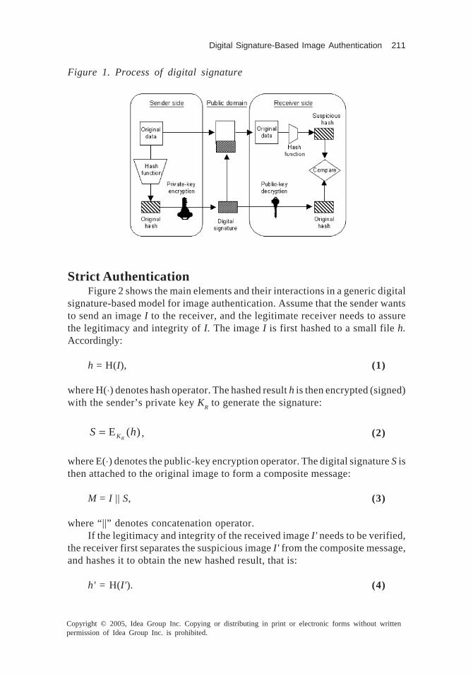
Digital Signature-Based Image Authentication 211
Copyright © 2005, Idea Group Inc. Copying or distributing in print or electronic forms without writtenpermission of Idea Group Inc. is prohibited.
Strict AuthenticationFigure 2 shows the main elements and their interactions in a generic digital
signature-based model for image authentication. Assume that the sender wantsto send an image I to the receiver, and the legitimate receiver needs to assurethe legitimacy and integrity of I. The image I is first hashed to a small file h.Accordingly:
h = H(I), (1)
where H(⋅) denotes hash operator. The hashed result h is then encrypted (signed)with the sender’s private key K
R to generate the signature:
)(E hSRK= , (2)
where E(⋅) denotes the public-key encryption operator. The digital signature S isthen attached to the original image to form a composite message:
M = I || S, (3)
where “||” denotes concatenation operator.If the legitimacy and integrity of the received image I' needs to be verified,
the receiver first separates the suspicious image I' from the composite message,and hashes it to obtain the new hashed result, that is:
h' = H(I'). (4)
Figure 1. Process of digital signature
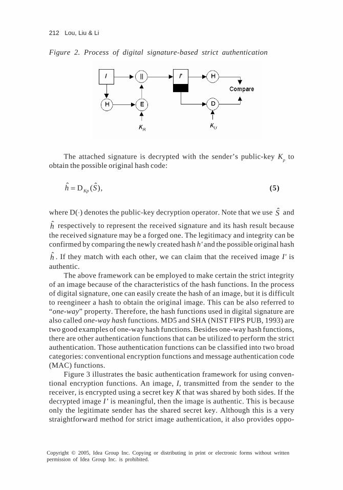
212 Lou, Liu & Li
Copyright © 2005, Idea Group Inc. Copying or distributing in print or electronic forms without writtenpermission of Idea Group Inc. is prohibited.
The attached signature is decrypted with the sender’s public-key Kp to
obtain the possible original hash code:
)ˆ(Dˆ Sh Kp= , (5)
where D(⋅) denotes the public-key decryption operator. Note that we use S and
h respectively to represent the received signature and its hash result becausethe received signature may be a forged one. The legitimacy and integrity can beconfirmed by comparing the newly created hash h' and the possible original hash
h . If they match with each other, we can claim that the received image I' isauthentic.
The above framework can be employed to make certain the strict integrityof an image because of the characteristics of the hash functions. In the processof digital signature, one can easily create the hash of an image, but it is difficultto reengineer a hash to obtain the original image. This can be also referred to“one-way” property. Therefore, the hash functions used in digital signature arealso called one-way hash functions. MD5 and SHA (NIST FIPS PUB, 1993) aretwo good examples of one-way hash functions. Besides one-way hash functions,there are other authentication functions that can be utilized to perform the strictauthentication. Those authentication functions can be classified into two broadcategories: conventional encryption functions and message authentication code(MAC) functions.
Figure 3 illustrates the basic authentication framework for using conven-tional encryption functions. An image, I, transmitted from the sender to thereceiver, is encrypted using a secret key K that was shared by both sides. If thedecrypted image I’ is meaningful, then the image is authentic. This is becauseonly the legitimate sender has the shared secret key. Although this is a verystraightforward method for strict image authentication, it also provides oppo-
Figure 2. Process of digital signature-based strict authentication

Digital Signature-Based Image Authentication 213
Copyright © 2005, Idea Group Inc. Copying or distributing in print or electronic forms without writtenpermission of Idea Group Inc. is prohibited.
nents opportunities to forge a meaningful image. For example, if an opponent hasthe pair of (I, C), he/she can forge an intelligible image I' by the cutting andpasting method (Li, Lou & Liu, 2003). One solution to this problem is to use themessage authentication code (MAC).
Figure 4 demonstrates the basic model of MAC-based strict authentication.The MAC is a cryptographic checksum that is first generated with a sharedsecret key before the transmission of the original image I. The MAC is thentransmitted to the receiver along with the original image. In order to assure theintegrity, the receiver conducts the same calculation on the received image I' usingthe same secret key to generate a new MAC. If the received MAC matches thecalculated MAC, then the integrity of the received image is verified. This isbecause if an attacker alters the original image without changing the MAC, thenthe newly calculated MAC will still differ from the received MAC.
The MAC function is similar to the encryption one. One difference is thatthe MAC algorithm does not need to be reversible. Nevertheless, the decryptionformula must be reversible. It results from the mathematical properties of theauthentication function. It is less vulnerable to be broken than the encryptionfunction. Although MAC-based strict authentication can detect the fake imagecreated by an attacker, it cannot avoid “legitimate” forgery. This is because boththe sender and the receiver share the same secret key. Therefore, the receivercan create a fake image with the shared secret key, and claim that this createdimage is received from the legitimate sender.
With the existing problems of encryption and MAC functions, the digitalsignature-based method seems a better way to perform strict authentication.
Figure 3. Process of encryption function-based strict authentication
Figure 4. Process of MAC-based strict authentication

214 Lou, Liu & Li
Copyright © 2005, Idea Group Inc. Copying or distributing in print or electronic forms without writtenpermission of Idea Group Inc. is prohibited.
Following the increasing applications that can tolerate one or more content-preserving manipulations, non-strict authentication becomes more and moreimportant nowadays.
Non-Strict AuthenticationFigure 5 shows the process of non-strict authentication. As we can see, the
procedure of non-strict authentication is similar to that of strict authenticationexcept that the function here used to digest the image is a special-design featureextraction function f
C.
Assume that the sender wants to deliver an image I to the receiver. Afeature extraction function f
C is used to extract the image feature and to encode
it to a small feature code:
C = fC(I), (6)
where fC (⋅) denotes feature extraction and coding operator. The extracted
feature code has three significant properties. First, the size of extracted featurecode is relatively small compared to the size of the original image. Second, itpreserves the characteristics of the original image. Third, it can tolerateincidental modifications of the original image. The feature code C is thenencrypted (signed) with the sender’s private key K
R to generate the signature:
)(E CSRK= . (7)
The digital signature S is then attached to the original image to form acomposite message:
M = I || S. (8)
Figure 5. Process of non-strict authentication
Digital Signature-Based Image Authentication 215
Copyright © 2005, Idea Group Inc. Copying or distributing in print or electronic forms without writtenpermission of Idea Group Inc. is prohibited.
Then the composite message M is forwarded to the receiver. The originalimage may be lossy compressed, decompressed, or tampered during transmis-sion. Therefore, the received composite message may include a corrupted imageI'. The original I may be compressed prior to the concatenation operation. If alossy compression strategy is adopted, the original image I in the compositemessage can be considered as a corrupted one.
In order to verify the legitimacy and integrity of the received image I', thereceiver first separates the corrupted image I' from the composite message, andgenerates a feature code C' by using the same feature extraction function in thesender side, that is:
C' = fC(I'). (9)
The attached signature is decrypted with the sender’s public-key KU to
obtain the original feature code:
)ˆ(Dˆ SCUK= . (10)
Note that we use S and C to represent the received signature and featurecode here because the signature may be forged.
The legitimacy and integrity can be verified by comparing the newly
generated feature C' and the received feature code C . To differentiate theerrors caused by authorized modifications from the errors of malevolent manipu-lations, let d(C, C') be the measurement of similarity between the extractedfeatures and the original. Let T denote a tolerable threshold value for examiningthe values of d(C, C') (e.g., it can be obtained by performing a maximumcompression to an image). The received image may be considered authentic ifthe condition < T is met.
Defining a suitable function to generate a feature code that satisfies therequirements for non-strict authentication is another issue. Ideally, employing afeature code should be able to detect content-changing modifications andtolerate content-preserving modifications. The content-changing modificationsmay include cropping, object addition, deletion, and modification, and so forth,while the content-preserving modifications may include lossy compression,format conversion and contrast enhancing, etc.
It is difficult to devise a feature code that is sensitive to all the content-changing modifications, while it remains insensitive to all the content-preservingmodifications. A practical approach to design a feature extraction functionwould be based on the manipulation methods (e.g., JPEG lossy compression). Aswe will see in the next section, most of the proposed non-strict authenticationtechniques are based on this idea.

216 Lou, Liu & Li
Copyright © 2005, Idea Group Inc. Copying or distributing in print or electronic forms without writtenpermission of Idea Group Inc. is prohibited.
STATE OF THE ARTIn this section, several existing digital signature-based image authentication
schemes are detailed. Specifically, works related strict authentication is de-scribed in the first subsection and non-strict ones in the second subsection. Notethat the intention of this section is to describe the methodology of the techniques.Some related problems about these techniques will be further discussed in thefourth section, in which some issues of designing practical schemes of digitalsignature-based image authentication are also discussed.
Strict AuthenticationFriedman (1993) associated the idea of digital signature with digital camera,
and proposed a “trustworthy digital camera,” which is illustrated as Figure 6. Theproposed digital camera uses a digital sensor instead of film, and delivers theimage directly in a computer-compatible format. A secure microprocessor isassumed to be built in the digital camera and be programmed with the private keyat the factory for the encryption of the digital signature. The public key necessaryfor later authentication appears on the camera body as well as the image’sborder. Once the digital camera captures the objective image, it produces twooutput files. One is an all-digital industry-standard file format representing thecaptured image; the other is an encrypted digital signature generated by applyingthe camera’s unique private key (embedded in the camera’s secure micropro-cessor) to a hash of the captured image file, a procedure described in the second
Figure 6. Idea of the trustworthy digital camera
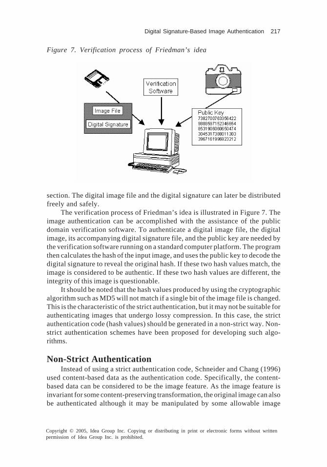
Digital Signature-Based Image Authentication 217
Copyright © 2005, Idea Group Inc. Copying or distributing in print or electronic forms without writtenpermission of Idea Group Inc. is prohibited.
section. The digital image file and the digital signature can later be distributedfreely and safely.
The verification process of Friedman’s idea is illustrated in Figure 7. Theimage authentication can be accomplished with the assistance of the publicdomain verification software. To authenticate a digital image file, the digitalimage, its accompanying digital signature file, and the public key are needed bythe verification software running on a standard computer platform. The programthen calculates the hash of the input image, and uses the public key to decode thedigital signature to reveal the original hash. If these two hash values match, theimage is considered to be authentic. If these two hash values are different, theintegrity of this image is questionable.
It should be noted that the hash values produced by using the cryptographicalgorithm such as MD5 will not match if a single bit of the image file is changed.This is the characteristic of the strict authentication, but it may not be suitable forauthenticating images that undergo lossy compression. In this case, the strictauthentication code (hash values) should be generated in a non-strict way. Non-strict authentication schemes have been proposed for developing such algo-rithms.
Non-Strict AuthenticationInstead of using a strict authentication code, Schneider and Chang (1996)
used content-based data as the authentication code. Specifically, the content-based data can be considered to be the image feature. As the image feature isinvariant for some content-preserving transformation, the original image can alsobe authenticated although it may be manipulated by some allowable image
Figure 7. Verification process of Friedman’s idea
218 Lou, Liu & Li
Copyright © 2005, Idea Group Inc. Copying or distributing in print or electronic forms without writtenpermission of Idea Group Inc. is prohibited.
transformations. The edge information, DCT coefficients, color, and intensityhistograms are regarded as potentially invariant features. In Schneider andChang’s method, the intensity histogram is employed as the invariant feature inthe implementation of the content-based image authentication scheme. To beeffective, the image is divided into blocks of variable sizes and the intensityhistogram of each block is computed separately and is used as the authenticationcode.
To tolerate incidental modifications, the Euclidean distance between inten-sity histograms was used as a measure of the content of the image. It is reportedthat the lossy compression ratio that could be applied to the image withoutproducing a false positive is limited to 4:1 at most. Schneider and Chang alsopointed out that using a reduced distance function can increase the maximumpermissible compression ratio. It is found that the alarm was not triggered evenat a high compression ratio up to 14:1 if the block average intensity is used fordetecting image content manipulation. Several works have been proposed in theliterature based on this idea. They will be introduced in the rest of this subsection.
Feature-Based MethodsThe major purpose of using the image digest (hash values) as the signature
is to speed up the signing procedure. It will violate the principle of the digitalsignature if large-size image features were adopted in the authenticationscheme. Bhattacharjee and Kutter (1998) proposed another algorithm to extracta smaller size feature of an image. Their feature extraction algorithm is basedon the so-called scale interaction model. Instead of using Gabor wavelets, theyadopted Mexican-Hat wavelets as the filter for detecting the feature points. Thealgorithm for detecting feature-points is depicted as follows.
• Define the feature-detection function, Pij(⋅) as:
( ) | ( ) ( ) |ij i jP x M x M xγ= − ⋅� � �
(11)
where ( )iM x�
and ( )jM x�
represent the responses of Mexican-Hat wave-
lets at the image-location x�
for scales i and j, respectively. For the image
A, the wavelet response ( )iM x�
is given by:
( ) (2 (2 ));i iiM x x Aψ− −= ⟨ ⋅ ⟩� �
(12)
where <⋅;⋅> denotes the convolution of its operands. The normalizingconstant γ is given by γ = 2-(i-j) , the operator |⋅| returns the absolute value

Digital Signature-Based Image Authentication 219
Copyright © 2005, Idea Group Inc. Copying or distributing in print or electronic forms without writtenpermission of Idea Group Inc. is prohibited.
of its parameter, and the ( )xψ �
represents the response of the Mexican-Hatmother wavelet, and is defined as:
22( ) (2 | | ) exp( )
2
xx xψ = − −
�
� �
(13)
• Determine points of local maximum of Pij(⋅). These points correspond to the
set of potential feature points.• Accept a point of local maximum in P
ij(⋅) as a feature-point if the variance
of the image-pixels in the neighborhood of the point is higher than athreshold. This criterion eliminates suspicious local maximum in featurelessregions of the image.
The column-positions and row-positions of the resulting feature points areconcatenated to form a string of digits, and then encrypted to generate the imagesignature. It is not hard to imagine that the file constructed in this way can havea smaller size compared to that constructed by recording the block histogram.
In order to determine whether an image A is authentic with another knownimage B, the feature set S
A of A is computed. The feature set S
A is then compared
with the feature set SB of B that is decrypted from the signature of B. The
following rules are adopted to authenticate the image A.
• Verify that each feature location is present both in SB and in S
A.
• Verify that no feature location is present in SA but absent in S
B.
• Two feature points with coordinates x�
and y�
are said to match if:
| | 2x y− <� �
(14)
Edge-Based MethodsThe edges in an image are the boundaries or contours where the significant
changes occur in some physical aspects of an image, such as the surfacereflectance, illumination, or the distances of the visible surfaces from the viewer.Edges are kinds of strong content features for an image. However, for commonpicture formats, coding edges value and position produces a huge overhead. Oneway to resolve this problem is to use a binary map to represent the edge. Forexample, Li, Lou and Liu (2003) used a binary map to encode the edges of animage in their watermarking-based image authentication scheme. It should beconcerned that edges (both their position and value, and also the resulting binaryimage) might be modified if high compression ratios are used. Consequently, thesuccess of using edges as the authentication code is greatly dependent on the

220 Lou, Liu & Li
Copyright © 2005, Idea Group Inc. Copying or distributing in print or electronic forms without writtenpermission of Idea Group Inc. is prohibited.
capacity of the authentication system to discriminate the differences the edgesproduced by content-preserving manipulations from those content-changingmanipulations. Queluz (2001) proposed an algorithm for edges extraction andedges integrity evaluation.
The block diagram of the edge extraction process of Queluz’s method isshown as Figure 8. The gradient is first computed at each pixel position with anedge extraction operator. The result is then compared with an image-dependentthreshold obtained from the image gradient histogram to obtain a binary imagemarking edge and no-edge pixels. Depending on the specifications for label size,the bit-map could be sub-sampled with the purpose of reducing its spatialresolution. Finally, the edges of the bit-map are encoded (compressed).
Edges integrity evaluation process is shown as Figure 9. In the edgesdifference computation block, the suspicious error pixels that have differencesbetween the original and computed edge bit-maps and a certitude value associ-ated with each error pixel are produced. These suspicious error pixels areevaluated in an error relaxation block. This is done by iteratively changing lowcertitude errors to high certitude errors if necessary, until no further changeoccurs. At the end, all high certitude errors are considered to be true errors and
Figure 8. Process of edge extraction proposed by Queluz (2001)
Figure 9. Process of edges integrity evaluation proposed by Queluz (2001)
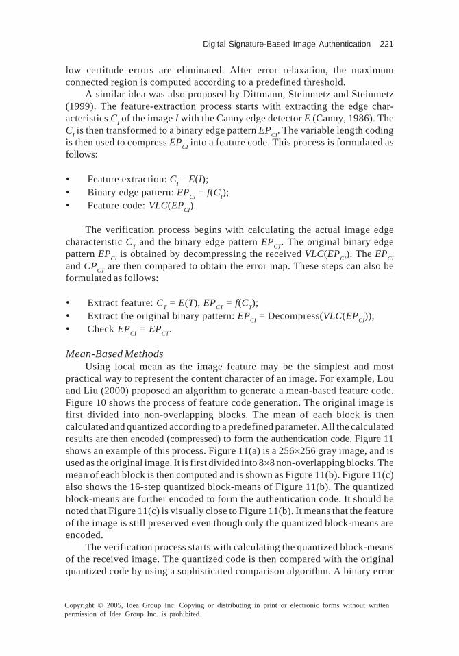
Digital Signature-Based Image Authentication 221
Copyright © 2005, Idea Group Inc. Copying or distributing in print or electronic forms without writtenpermission of Idea Group Inc. is prohibited.
low certitude errors are eliminated. After error relaxation, the maximumconnected region is computed according to a predefined threshold.
A similar idea was also proposed by Dittmann, Steinmetz and Steinmetz(1999). The feature-extraction process starts with extracting the edge char-acteristics C
I of the image I with the Canny edge detector E (Canny, 1986). The
CI is then transformed to a binary edge pattern EP
CI. The variable length coding
is then used to compress EPCI
into a feature code. This process is formulated asfollows:
• Feature extraction: CI = E(I);
• Binary edge pattern: EPCI
= f(CI);
• Feature code: VLC(EPCI
).
The verification process begins with calculating the actual image edgecharacteristic C
T and the binary edge pattern EP
CT. The original binary edge
pattern EPCI
is obtained by decompressing the received VLC(EPCI
). The EPCI
and CPCT
are then compared to obtain the error map. These steps can also beformulated as follows:
• Extract feature: CT = E(T), EP
CT = f(C
T);
• Extract the original binary pattern: EPCI
= Decompress(VLC(EPCI
));• Check EP
CI = EP
CT.
Mean-Based MethodsUsing local mean as the image feature may be the simplest and most
practical way to represent the content character of an image. For example, Louand Liu (2000) proposed an algorithm to generate a mean-based feature code.Figure 10 shows the process of feature code generation. The original image isfirst divided into non-overlapping blocks. The mean of each block is thencalculated and quantized according to a predefined parameter. All the calculatedresults are then encoded (compressed) to form the authentication code. Figure 11shows an example of this process. Figure 11(a) is a 256×256 gray image, and isused as the original image. It is first divided into 8×8 non-overlapping blocks. Themean of each block is then computed and is shown as Figure 11(b). Figure 11(c)also shows the 16-step quantized block-means of Figure 11(b). The quantizedblock-means are further encoded to form the authentication code. It should benoted that Figure 11(c) is visually close to Figure 11(b). It means that the featureof the image is still preserved even though only the quantized block-means areencoded.
The verification process starts with calculating the quantized block-meansof the received image. The quantized code is then compared with the originalquantized code by using a sophisticated comparison algorithm. A binary error
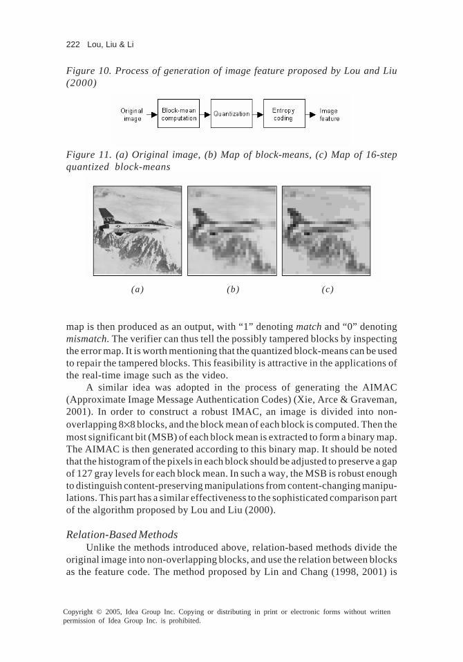
222 Lou, Liu & Li
Copyright © 2005, Idea Group Inc. Copying or distributing in print or electronic forms without writtenpermission of Idea Group Inc. is prohibited.
map is then produced as an output, with “1” denoting match and “0” denotingmismatch. The verifier can thus tell the possibly tampered blocks by inspectingthe error map. It is worth mentioning that the quantized block-means can be usedto repair the tampered blocks. This feasibility is attractive in the applications ofthe real-time image such as the video.
A similar idea was adopted in the process of generating the AIMAC(Approximate Image Message Authentication Codes) (Xie, Arce & Graveman,2001). In order to construct a robust IMAC, an image is divided into non-overlapping 8×8 blocks, and the block mean of each block is computed. Then themost significant bit (MSB) of each block mean is extracted to form a binary map.The AIMAC is then generated according to this binary map. It should be notedthat the histogram of the pixels in each block should be adjusted to preserve a gapof 127 gray levels for each block mean. In such a way, the MSB is robust enoughto distinguish content-preserving manipulations from content-changing manipu-lations. This part has a similar effectiveness to the sophisticated comparison partof the algorithm proposed by Lou and Liu (2000).
Relation-Based MethodsUnlike the methods introduced above, relation-based methods divide the
original image into non-overlapping blocks, and use the relation between blocksas the feature code. The method proposed by Lin and Chang (1998, 2001) is
Figure 10. Process of generation of image feature proposed by Lou and Liu(2000)
Figure 11. (a) Original image, (b) Map of block-means, (c) Map of 16-stepquantized block-means
(a) (b) (c)

Digital Signature-Based Image Authentication 223
Copyright © 2005, Idea Group Inc. Copying or distributing in print or electronic forms without writtenpermission of Idea Group Inc. is prohibited.
called SARI. The feature code in SARI is generated to survive the JPEGcompression. To serve this purpose, the process of the feature code generationstarts with dividing the original image into 8×8 non-overlapping blocks. Eachblock is then DCT transformed. The transformed DCT blocks are furthergrouped into two non-overlapping sets. There are equal numbers of DCT blocksin each set (i.e., there are N/2 DCT blocks in each set if the original image isdivided into N blocks). A secret key-dependent mapping function then one-to-one maps each DCT block in one set into another DCT block in the other set, andgenerates N/2 DCT block pairs. For each block pair, a number of DCTcoefficients are then selected and compared. The feature code is then generatedby comparing the corresponding coefficients of the paired blocks. For example,if the coefficient in the first DCT block is greater than the coefficient in thesecond DCT block, then code is generated as “1”. Otherwise, a “0” is generated.The process of generating the feature code is illustrated as Figure 12.
To extract the feature code of the received image, the same secret keyshould be applied in the verification process. The extracted feature code is thencompared with the original feature code. If either block in each block pair hasnot been maliciously manipulated, the relation between the selected coefficientsis maintained. Otherwise, the relation between the selected coefficients may bechanged.
It can be proven that the relationship between the selected DCT coeffi-cients of two given image blocks is maintained even after the JPEG compressionby using the same quantization matrix for the whole image. Consequently, SARIauthentication system can distinguish JPEG compression from other maliciousmanipulations. Moreover, SARI can locate the tampered blocks because it is ablock-wise method.
Figure 12. Feature code generated with SARI authentication scheme

224 Lou, Liu & Li
Copyright © 2005, Idea Group Inc. Copying or distributing in print or electronic forms without writtenpermission of Idea Group Inc. is prohibited.
Structure-Based MethodsLu and Liao (2000, 2003) proposed another kind of method to generate the
feature code. The feature code is generated according to the structure of theimage content. More specifically, the content structure of an image is composedof parent-child pairs in the wavelet domain. Let w
s,o(x, y) be a wavelet coefficient
at the scale s. Orientation o denotes horizontal, vertical, or diagonal direction.The inter-scale relationship of wavelet coefficients is defined for the parentnode w
s+1,o(x, y) and its four children nodes w
s,o(2x+i, 2y+j) as either
|ws+1,o
(x, y)| ≥ |ws,o
(2x+i, 2y+j)| or |ws+1,o
(x, y)| ≤ |ws,o
(2x+i, 2y+j)|, where 0 ≤ i,j ≤ 1.
The authentication code is generated by recording the parent-child pair thatsatisfies ||w
s+1,o(x, y)| - |w
s,o(2x+i, 2y+j)|| > ρ , where ρ > 0. Clearly, the threshold
ρ is used to determine the size of the authentication code, and plays a trade-offrole between robustness and fragility. It is proven that the inter-scale relationshipis difficult to be destroyed by content-preserving manipulations and is hard to bepreserved by content-changing manipulations.
DESIGN ISSUESDigital signature-based image authentication is an important element in the
applications of image communication. Usually, the content verifiers are not thecreator or the sender of the original image. That means the original image is notavailable during the authentication process. Therefore, one of the fundamentalrequirements for digital signature-based image authentication schemes is blindauthentication, or obliviousness, as it is sometimes called. Other requirementsdepend on the applications that may be based on strict authentication or non-strictauthentication. In this section, we will discuss some issues about designingeffective digital signature-based image authentication schemes.
Error DetectionIn some applications, it is proper if modification of an image can be detected
by authentication schemes. However, it is beneficial if the authenticationschemes are able to detect or estimate the errors so that the distortion can becompensated or even corrected. Techniques for error detection can be catego-rized into two classes according to the applications of image authentication;namely, error type and error location.
Error TypeGenerally, strict authentication schemes can only determine whether the
content of the original image is modified. This also means that they are not ableto differentiate the types of distortion (e.g., compression or filtering). Bycontrast, non-strict authentication schemes tend to tolerate some form of errors.
Digital Signature-Based Image Authentication 225
Copyright © 2005, Idea Group Inc. Copying or distributing in print or electronic forms without writtenpermission of Idea Group Inc. is prohibited.
The key to developing a non-strict authentication scheme is to examine what thedigital signature should protect. Ideally, the authentication code should protectthe message conveyed by the content of the image, but not the particularrepresentation of that content of the image. Therefore, the authentication codecan be used to verify the authenticity of an image that has been incidentallymodified, leaving the value and meaning of its contents unaffected. Ideally, onecan define an authenticity versus modification curve such as the methodproposed by Schneider and Chang (1996) to achieve the desired authenticity.Based on the authenticity versus modification curve, authentication is no longera yes-or-no question. Instead, it is a continuous interpretation. An image that isbit by bit identical to the original image has an authenticity measure of 1.0 andis considered to be completely authentic. An image that has nothing in commonwith the original image has an authenticity measure of 0.0 and is consideredunauthentic. Each of the other images would have authenticity measure betweenthe range (0.0, 1.0) and be partially authentic.
Error LocationAnother desirable requirement for error detection in most applications is
errors localization. This can be achieved by block-oriented approaches. Beforetransmission, an image is usually partitioned into blocks. The authentication codeof each block is calculated (either for strict or non-strict authentication). Theauthentication codes of the original image are concatenated, signed, and trans-mitted as a separate file. To locate the distorted regions during the authenticatingprocess, the received image is partitioned into blocks first. The authenticationcode of each block is calculated and compared with the authentication coderecovered from the received digital signature. Therefore, the smaller the blocksize is, the better the localization accuracy is. However, the higher accuracy isgained at the expense of the larger authentication code file and the longer processof signing and decoding. The trade-off needs to be taken into account at thedesigning stage of an authentication scheme.
Error CorrectionThe purpose of error correction is to recover the original images from their
manipulated version. This requirement is essential in the applications of militaryintelligence and motion pictures (Dittmann, Steinmetz & Steinmetz, 1999;Queluz, 2001). Error correction can be achieved by means of error correctioncode (ECC) (Lin & Costello, 1983). However, encrypting ECC along withfeature code may result in a lengthy signature. Therefore, it is more advanta-geous to enable the authentication code itself to be the power of error correction.Unfortunately, the authentication code generated by strict authentication schemesis meaningless and cannot be used to correct the errors. Compared to strictauthentication, the authentication code generated by non-strict authentication

226 Lou, Liu & Li
Copyright © 2005, Idea Group Inc. Copying or distributing in print or electronic forms without writtenpermission of Idea Group Inc. is prohibited.
schemes is potentially capable of error correction. This is because the authen-tication code generated by the non-strict authentication is usually derived fromthe image feature and is highly content dependent.
An example of using authentication code for image error correction can befound in Xie, Arce and Graveman (2001). This work uses quantized image grayvalues as authentication code. The authenticated code is potentially capable oferror correcting since image features are usually closely related to image grayvalues. It should be noted that the smaller the quantization step is, the better theperformance of error correction is. However, a smaller quantization step alsomeans a longer signature. Therefore, trade-off between the performance oferror correction and the length of signature has to be made as well. This is,without doubt, an acute challenge, and worth further researching.
SecurityWith the protection of public-key encryption, the security of the digital
signature-based image authentication is reduced to the security of the imagedigest function that is used to produce the authentication code. For strictauthentication, the attacks on hash functions can be grouped into two categories:brute-force attacks and cryptanalysis attacks.
Brute-force AttacksIt is believed that, for a general-purpose secure hash code, the strength of
a hash function against brute-force attacks depends solely on the length of thehash code produced by the algorithm. For a code of length n, the level of effortrequired is proportional to 2n/2. This is also known as birthday attack. Forexample, the length of the hash code of MD5 (Rivest, 1992) is 128 bits. If anattacker has 264 different samples, he or she has more than 50% of chances tofind the same hash code. In other words, to create a fake image that has the samehash result as the original image, an attacker only needs to prepare 264 visuallyequivalent fake images. This can be accomplished by first creating a fake imageand then varying the least significant bit of each of 64 arbitrarily chosen pixelsof the fake image. It has been proved that we could find a collision in 24 days byusing a $10 million collision search machine for MD5 (Stallings, 2002). A simplesolution to this problem is to use a hash function to produce a longer hash code.For example, SHA-1 (NIST FIPS PUB 180, 1993) and RIPEMD-160 (Stallings,2002) can provide 160-bit hash code. It is believed that over 4,000 years wouldbe required if we used the same search machine to find a collision (Oorschot &Wiener, 1994). Another way to resolve this problem is to link the authenticationcode with the image feature such as the strategy adopted by non-strictauthentication.
Non-strict authentication employs image feature as the image digest. Thismakes it harder to create enough visually equivalent fake images to forge a legal

Digital Signature-Based Image Authentication 227
Copyright © 2005, Idea Group Inc. Copying or distributing in print or electronic forms without writtenpermission of Idea Group Inc. is prohibited.
one. It should be noted that, mathematically, the relationship between the originalimage and the authentication code is many-to-one mapping. To serve the purposeof error tolerance, non-strict authentication schemes may have one authentica-tion code corresponding to more images. This phenomenon makes non-strictauthentication approaches vulnerable and remains as a serious design issue.
Cryptanalysis AttacksCryptanalysis attacks on digest function seek to exploit some property of the
algorithm to perform some attack rather than an exhaustive search. Cryptanalysison the strict authentication scheme is to exploit the internal structure of the hashfunction. Therefore, we have to select a secure hash function that can resistcryptanalysis performed by attackers. Fortunately, so far, SHA-1 and RIPEMD-160 are still secure for various cryptanalyses and can be included in strictauthentication schemes. Cryptanalysis on non-strict authentication has not beendefined so far. It may refer to the analysis of key-dependent digital signature-based schemes. In this case, an attacker tries to derive the secret key frommultiple feature codes, which is performed in a SARI image authenticationsystem (Radhakrisnan & Memon, 2001). As defined in the second section, thereis no secret key involved in a digital signature-based authentication scheme. Thismeans that the secrecy of the digital signature-based authentication schemesdepends on the robustness of the algorithm itself and needs to be noted fordesigning a secure authentication scheme.
CONCLUSIONSWith the advantages of the digital signature (Agnew, Mullin & Vanstone,
1990; ElGamal, 1985; Harn, 1994; ISO/IEC 9796, 1991; NIST FIPS PUB, 1993;Nyberg & Rueppel, 1994; Yen & Laih, 1995), digital signature-based schemesare more applicable than any other schemes in image authentication. Dependingon applications, digital signature-based authentication schemes are divided intostrict and non-strict categories and are described in great detail in this chapter.For strict authentication, the authentication code derived from the calculation oftraditional hash function is sufficiently short. This property enables fast creationof the digital signature. In another aspect, the arithmetic-calculated hash is verysensitive to the modification of image content. Some tiny changes to a single bitin an image may result in a different hash. This results in that strict authenticationcan provide binary authentication (i.e., yes or no). The trustworthy camera is atypical example of this type of authentication scheme.
For some image authentication applications, the authentication code shouldbe sensitive for content-changing modification and can tolerate some content-preserving modification. In this case, the authentication code is asked to satisfysome basic requirements. Those requirements include locating modification

228 Lou, Liu & Li
Copyright © 2005, Idea Group Inc. Copying or distributing in print or electronic forms without writtenpermission of Idea Group Inc. is prohibited.
regions and tolerating some forms of image processing operations (e.g., JPEGlossy compression). Many non-strict authentication techniques are also de-scribed in this chapter. Most of them are designed to employ a special-purposeauthentication code to satisfy those basic requirements shown above. However,few of them are capable of recovering some certain errors. This special-purposeauthentication code may be the modern and useful aspect for non-strictauthentication.
Under the quick evolution of image processing techniques, existing digitalsignature-based image authentication schemes will be further improved to meetnew requirements. New requirements pose new challenges for designingeffective digital signature-based authentication schemes. These challenges mayinclude using large-size authentication code and tolerating more image-process-ing operations without compromising security. This means that new approacheshave to balance the trade-off among these requirements. Moreover, moremodern techniques combining the watermark and digital signature techniquesmay be proposed for new image authentication generations. Those new imageauthentication techniques may result in some changes of the watermark anddigital signature framework, as demonstrated in Sun and Chang (2002), Sun,Chang, Maeno and Suto (2002a, 2002b) and Lou and Sung (to appear).
REFERENCESAgnew, G.B., Mullin, R.C., & Vanstone, S.A. (1990). Improved digital signature
scheme based on discrete exponentiation. IEEE Electronics Letters, 26,1024-1025.
Bhattacharjee, S., & Kutter, M. (1998). Compression tolerant image authenti-cation. Proceedings of the International Conference on Image Pro-cessing, 1, 435-439.
Canny, J. (1986). A computational approach to edge detection. IEEE Transac-tions on Pattern Analysis and Machine Intelligence, PAMI-8(6), 679-698.
Diffie, W., & Hellman, M.E. (1976). New directions in cryptography. IEEETransactions on Information Theory, IT-22(6), 644-654.
Dittmann, J., Steinmetz, A., & Steinmetz, R. (1999). Content-based digitalsignature for motion pictures authentication and content-fragilewatermarking. Proceedings of the IEEE International Conference OnMultimedia Computing and Systems, 2, 209-213.
ElGamal, T. (1985). A public-key cryptosystem and a signature scheme basedon discrete logarithms. IEEE Transactions on Information Theory, IT-31(4), 469-472.
Friedman, G.L. (1993). The trustworthy digital camera: Restoring credibility tothe photographic image. IEEE Transactions on Consumer Electronics,39(4), 905-910.

Digital Signature-Based Image Authentication 229
Copyright © 2005, Idea Group Inc. Copying or distributing in print or electronic forms without writtenpermission of Idea Group Inc. is prohibited.
Harn, L. (1994). New digital signature scheme based on discrete logarithm. IEEElectronics Letters, 30(5), 396-398.
ISO/IEC 9796. (1991). Information technology security techniques digital signa-ture scheme giving message recovery. International Organization forStandardization.
Li, C.-T., Lou, D.-C., & Chen, T.-H. (2000). Image authentication via content-based watermarks and a public key cryptosystem. Proceedings of theIEEE International Conference on Image Processing, 3, 694-697.
Li, C.-T., Lou, D.-C., & Liu, J.-L. (2003). Image integrity and authenticityverification via content-based watermarks and a public key cryptosystem.Journal of the Chinese Institute of Electrical Engineering, 10(1), 99-106.
Lin, C.-Y., & Chang, S.-F. (1998). A robust image authentication methodsurviving JPEG lossy compression. SPIE storage and retrieval of image/video databases. San Jose.
Lin, C.-Y., & Chang, S.-F. (2001). A robust image authentication methoddistinguishing JPEG Compression from malicious manipulation. IEEE Trans-actions on Circuits and Systems of Video Technology, 11(2), 153-168.
Lin, S., & Costello, D.J. (1983). Error control coding: Fundamentals andapplications. NJ: Prentice-Hall.
Lou, D.-C., & Liu, J.-L. (2000). Fault resilient and compression tolerant digitalsignature for image authentication. IEEE Transactions on ConsumerElectronics, 46(1), 31-39.
Lou, D.-C., & Sung, C.-H. (to appear). A steganographic scheme for securecommunications based on the chaos and Euler theorem. IEEE Transac-tions on Multimedia.
Lu, C.-S., & Liao, M.H.-Y. (2000). Structural digital signature for imageauthentication: An incidental distortion resistant scheme. Proceedings ofMultimedia and Security Workshop at the ACM International Confer-ence On Multimedia, pp. 115-118.
Lu, C.-S., & Liao, M.H.-Y. (2003). Structural digital signature for imageauthentication: An incidental distortion resistant scheme. IEEE Transac-tions on Multimedia, 5(2), 161-173.
NIST FIPS PUB. (1993). Digital signature standard. National Institute ofStandards and Technology, U.S. Department of Commerce, DRAFT.
NIST FIPS PUB 180. (1993). Secure hash standard. National Institute ofStandards and Technology, U.S. Department of Commerce, DRAFT.
Nyberg, K., & Rueppel, R. (1994). Message recovery for signature schemesbased on the discrete logarithm problem. Proceedings of Eurocrypt’94,175-190.
Oorschot, P.V., & Wiener, M.J. (1994). Parallel collision search with applicationto hash functions and discrete logarithms. Proceedings of the SecondACM Conference on Computer and Communication Security, 210-218.

230 Lou, Liu & Li
Copyright © 2005, Idea Group Inc. Copying or distributing in print or electronic forms without writtenpermission of Idea Group Inc. is prohibited.
Queluz, M.P. (2001). Authentication of digital images and video: Generic modelsand a new contribution. Signal Processing: Image Communication, 16,461-475.
Radhakrisnan, R., & Memon, N. (2001). On the security of the SARI imageauthentication system. Proceedings of the IEEE International Confer-ence on Image Processing, 3, 971-974.
Rivest, R.L. (1992). The MD5 message digest algorithm. Internet Request ForComments 1321.
Rivest, R.L., Shamir, A., & Adleman, L. (1978). A method for obtaining digitalsignatures and public-key cryptosystems. Communications of the ACM,21(2), 120-126.
Schneider, M., & Chang, S.-F. (1996). Robust content based digital signature forimage authentication. Proceedings of the IEEE International Confer-ence on Image Processing, 3, 227-230.
Stallings, W. (2002). Cryptography and network security: Principles andpractice (3rd ed.). New Jersey: Prentice-Hall.
Sun, Q., & Chang, S.-F. (2002). Semi-fragile image authentication using genericwavelet domain features and ECC. Proceedings of the 2002 Interna-tional Conference on Image Processing, 2, 901-904.
Sun, Q., Chang, S.-F., Maeno, K., & Suto, M. (2002a). A new semi-fragile imageauthentication framework combining ECC and PKI infrastructures. Pro-ceedings of the 2002 IEEE International Symposium on Circuits andSystems, 2, 440-443.
Sun, Q., Chang, S.-F., Maeno, K., & Suto, M. (2002b). A quantitive semi-fragileJPEG2000 image authentication system. Proceedings of the 2002 Inter-national Conference on Image Processing, 2, 921-924.
Wallace, G.K. (1991, April). The JPEG still picture compression standard.Communications of the ACM, 33, 30-44.
Walton, S. (1995). Image authentication for a slippery new age. Dr. Dobb’sJournal, 20(4), 18-26.
Xie, L., Arce, G.R., & Graveman, R.F. (2001). Approximate image messageauthentication codes. IEEE Transactions on Multimedia, 3(2), 242-252.
Yen, S.-M., & Laih, C.-S. (1995). Improved digital signature algorithm. IEEETransactions on Computers, 44(5), 729-730.

Data Hiding in Document Images 231
Copyright © 2005, Idea Group Inc. Copying or distributing in print or electronic forms without writtenpermission of Idea Group Inc. is prohibited.
Chapter VIII
Data Hiding inDocument Images
Minya Chen, Polytechnic University, USA
Nasir Memon, Polytechnic University, USA
Edward K. Wong, Polytechnic University, USA
ABSTRACTWith the proliferation of digital media such as images, audio, and video,robust digital watermarking and data hiding techniques are needed forcopyright protection, copy control, annotation, and authentication ofdocument images. While many techniques have been proposed for digitalcolor and grayscale images, not all of them can be directly applied to binaryimages in general and document images in particular. The difficulty lies inthe fact that changing pixel values in a binary image could introduceirregularities that are very visually noticeable. Over the last few years, wehave seen a growing but limited number of papers proposing new techniquesand ideas for binary image watermarking and data hiding. In this chapterwe present an overview and summary of recent developments on thisimportant topic, and discuss important issues such as robustness and datahiding capacity of the different techniques.
INTRODUCTIONGiven the increasing availability of cheap yet high quality scanners, digital
cameras, digital copiers, printers and mass storage media the use of documentimages in practical applications is becoming more widespread. However, the
232 Chen, Memon & Wong
Copyright © 2005, Idea Group Inc. Copying or distributing in print or electronic forms without writtenpermission of Idea Group Inc. is prohibited.
same technology that allows for creation, storage and processing of documentsin digital form, also provides means for mass copying and tampering ofdocuments. Given the fact that digital documents need to be exchanged in printedformat for many practical applications, any security mechanism for protectingdigital documents would have to be compatible with the paper-based infrastruc-ture. Consider for example the problem of authentication. Clearly an authenti-cation tag embedded in the document should survive the printing process. Thatmeans that the authentication tag should be embedded inside the document datarather than appended to the bitstream representing the document. The reason isthat if the authentication tag is appended to the bitstream, a forger could easilyscan the document, remove the tag, and make changes to the scanned copy andthen print the modified document.
The process of embedding information into digital content without causingperceptual degradation is called data hiding. A special case of data hiding isdigital watermarking where the embedded signal can depend on a secret key.One main difference between data hiding and watermarking is in whether anactive adversary is present. In watermarking applications like copyright protec-tion and authentication, there is an active adversary that would attempt toremove, invalidate or forge watermarks. In data hiding there is no such activeadversary as there is no value associated with the act of removing the hiddeninformation. Nevertheless, data hiding techniques need to be robust againstaccidental distortions.
A special case of data hiding is steganography (meaning covered writingin Greek), which is the science and art of secret communication. Althoughsteganography has been studied as part of cryptography for many decades, thefocus of steganography is secret communication. In fact, the modern formulationof the problem goes by the name of the prisoner’s problem. Here Alice and Bobare trying to hatch an escape plan while in prison. The problem is that allcommunication between them is examined by a warden, Wendy, who will placeboth of them in solitary confinement at the first hint of any suspicious commu-nication. Hence, Alice and Bob must trade seemingly inconspicuous messagesthat actually contain hidden messages involving the escape plan. There are twoversions of the problem that are usually discussed — one where the warden ispassive, and only observes messages, and the other where the warden is activeand modifies messages in a limited manner to guard against hidden messages.The most important issue in steganography is that the very presence of a hiddenmessage must be concealed. Such a requirement is not critical in general datahiding and watermarking problems.
Before we describe the different techniques that have been devised for datahiding, digital watermarking and steganography for document images, we brieflylist different applications that would be enabled by such techniques.
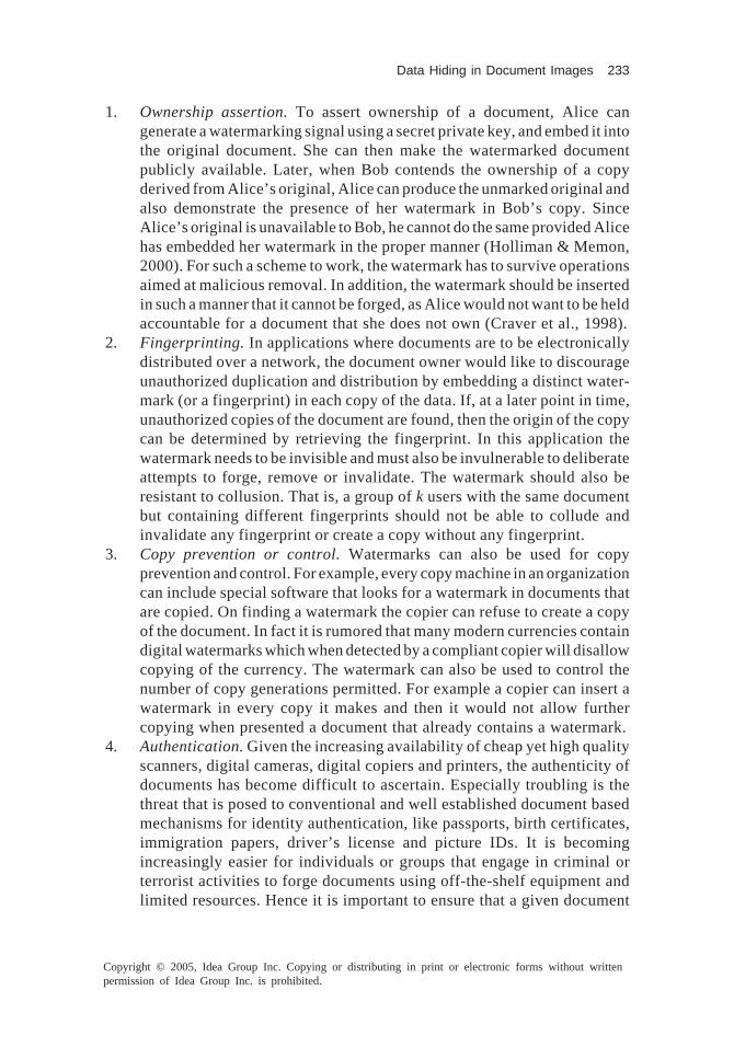
Data Hiding in Document Images 233
Copyright © 2005, Idea Group Inc. Copying or distributing in print or electronic forms without writtenpermission of Idea Group Inc. is prohibited.
1. Ownership assertion. To assert ownership of a document, Alice cangenerate a watermarking signal using a secret private key, and embed it intothe original document. She can then make the watermarked documentpublicly available. Later, when Bob contends the ownership of a copyderived from Alice’s original, Alice can produce the unmarked original andalso demonstrate the presence of her watermark in Bob’s copy. SinceAlice’s original is unavailable to Bob, he cannot do the same provided Alicehas embedded her watermark in the proper manner (Holliman & Memon,2000). For such a scheme to work, the watermark has to survive operationsaimed at malicious removal. In addition, the watermark should be insertedin such a manner that it cannot be forged, as Alice would not want to be heldaccountable for a document that she does not own (Craver et al., 1998).
2. Fingerprinting. In applications where documents are to be electronicallydistributed over a network, the document owner would like to discourageunauthorized duplication and distribution by embedding a distinct water-mark (or a fingerprint) in each copy of the data. If, at a later point in time,unauthorized copies of the document are found, then the origin of the copycan be determined by retrieving the fingerprint. In this application thewatermark needs to be invisible and must also be invulnerable to deliberateattempts to forge, remove or invalidate. The watermark should also beresistant to collusion. That is, a group of k users with the same documentbut containing different fingerprints should not be able to collude andinvalidate any fingerprint or create a copy without any fingerprint.
3. Copy prevention or control. Watermarks can also be used for copyprevention and control. For example, every copy machine in an organizationcan include special software that looks for a watermark in documents thatare copied. On finding a watermark the copier can refuse to create a copyof the document. In fact it is rumored that many modern currencies containdigital watermarks which when detected by a compliant copier will disallowcopying of the currency. The watermark can also be used to control thenumber of copy generations permitted. For example a copier can insert awatermark in every copy it makes and then it would not allow furthercopying when presented a document that already contains a watermark.
4. Authentication. Given the increasing availability of cheap yet high qualityscanners, digital cameras, digital copiers and printers, the authenticity ofdocuments has become difficult to ascertain. Especially troubling is thethreat that is posed to conventional and well established document basedmechanisms for identity authentication, like passports, birth certificates,immigration papers, driver’s license and picture IDs. It is becomingincreasingly easier for individuals or groups that engage in criminal orterrorist activities to forge documents using off-the-shelf equipment andlimited resources. Hence it is important to ensure that a given document
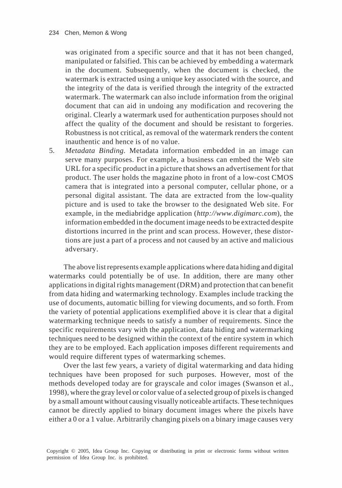
234 Chen, Memon & Wong
Copyright © 2005, Idea Group Inc. Copying or distributing in print or electronic forms without writtenpermission of Idea Group Inc. is prohibited.
was originated from a specific source and that it has not been changed,manipulated or falsified. This can be achieved by embedding a watermarkin the document. Subsequently, when the document is checked, thewatermark is extracted using a unique key associated with the source, andthe integrity of the data is verified through the integrity of the extractedwatermark. The watermark can also include information from the originaldocument that can aid in undoing any modification and recovering theoriginal. Clearly a watermark used for authentication purposes should notaffect the quality of the document and should be resistant to forgeries.Robustness is not critical, as removal of the watermark renders the contentinauthentic and hence is of no value.
5. Metadata Binding. Metadata information embedded in an image canserve many purposes. For example, a business can embed the Web siteURL for a specific product in a picture that shows an advertisement for thatproduct. The user holds the magazine photo in front of a low-cost CMOScamera that is integrated into a personal computer, cellular phone, or apersonal digital assistant. The data are extracted from the low-qualitypicture and is used to take the browser to the designated Web site. Forexample, in the mediabridge application (http://www.digimarc.com), theinformation embedded in the document image needs to be extracted despitedistortions incurred in the print and scan process. However, these distor-tions are just a part of a process and not caused by an active and maliciousadversary.
The above list represents example applications where data hiding and digitalwatermarks could potentially be of use. In addition, there are many otherapplications in digital rights management (DRM) and protection that can benefitfrom data hiding and watermarking technology. Examples include tracking theuse of documents, automatic billing for viewing documents, and so forth. Fromthe variety of potential applications exemplified above it is clear that a digitalwatermarking technique needs to satisfy a number of requirements. Since thespecific requirements vary with the application, data hiding and watermarkingtechniques need to be designed within the context of the entire system in whichthey are to be employed. Each application imposes different requirements andwould require different types of watermarking schemes.
Over the last few years, a variety of digital watermarking and data hidingtechniques have been proposed for such purposes. However, most of themethods developed today are for grayscale and color images (Swanson et al.,1998), where the gray level or color value of a selected group of pixels is changedby a small amount without causing visually noticeable artifacts. These techniquescannot be directly applied to binary document images where the pixels haveeither a 0 or a 1 value. Arbitrarily changing pixels on a binary image causes very
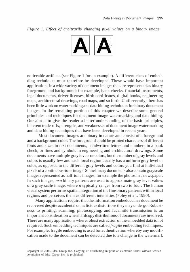
Data Hiding in Document Images 235
Copyright © 2005, Idea Group Inc. Copying or distributing in print or electronic forms without writtenpermission of Idea Group Inc. is prohibited.
noticeable artifacts (see Figure 1 for an example). A different class of embed-ding techniques must therefore be developed. These would have importantapplications in a wide variety of document images that are represented as binaryforeground and background; for example, bank checks, financial instruments,legal documents, driver licenses, birth certificates, digital books, engineeringmaps, architectural drawings, road maps, and so forth. Until recently, there hasbeen little work on watermarking and data hiding techniques for binary documentimages. In the remaining portion of this chapter we describe some generalprinciples and techniques for document image watermarking and data hiding.Our aim is to give the reader a better understanding of the basic principles,inherent trade-offs, strengths, and weaknesses of document image watermarkingand data hiding techniques that have been developed in recent years.
Most document images are binary in nature and consist of a foregroundand a background color. The foreground could be printed characters of differentfonts and sizes in text documents, handwritten letters and numbers in a bankcheck, or lines and symbols in engineering and architectural drawings. Somedocuments have multiple gray levels or colors, but the number of gray levels andcolors is usually few and each local region usually has a uniform gray level orcolor, as opposed to the different gray levels and colors you find at individualpixels of a continuous-tone image. Some binary documents also contain grayscaleimages represented as half-tone images, for example the photos in a newspaper.In such images, nxn binary patterns are used to approximate gray level valuesof a gray scale image, where n typically ranges from two to four. The humanvisual system performs spatial integration of the fine binary patterns within localregions and perceives them as different intensities (Foley et al., 1990).
Many applications require that the information embedded in a document berecovered despite accidental or malicious distortions they may undergo. Robust-ness to printing, scanning, photocopying, and facsimile transmission is animportant consideration when hardcopy distributions of documents are involved.There are many applications where robust extraction of the embedded data is notrequired. Such embedding techniques are called fragile embedding techniques.For example, fragile embedding is used for authentication whereby any modifi-cation made to the document can be detected due to a change in the watermark
Figure 1. Effect of arbitrarily changing pixel values on a binary image

236 Chen, Memon & Wong
Copyright © 2005, Idea Group Inc. Copying or distributing in print or electronic forms without writtenpermission of Idea Group Inc. is prohibited.
itself or a change in the relationship between the content and the watermark.Fragile embedding techniques could also be used for steganography applications.
In the second section, of this chapter, we summarize recent developmentsin binary document image watermarking and data hiding techniques. In the thirdsection, we present a discussion on these techniques, and in the fourth sectionwe give our concluding remarks.
DATA HIDING TECHNIQUES FORDOCUMENTS IMAGES
Watermarking and data hiding techniques for binary document images canbe classified according to one of the following embedding methods: text line,word, or character shifting, fixed partitioning of the image into blocks, boundarymodifications, modification of character features, modification of run-lengthpatterns, and modifications of half-tone images. In the rest of this section wedescribe representative techniques for each of these methods.
Text Line, Word or Character ShiftingOne class of robust embedding methods shifts a text line, a group of words,
or a group of characters by a small amount to embed data. They are applicableto documents with formatted text.
S. Low and co-authors have published a series of papers on documentwatermarking based on line and word shifting (Low et al., 1995a, 1995b, 1998;Low & Maxemchuk, 1998; Maxemchuk & Low, 1997). These methods areapplicable to documents that contain paragraphs of printed text. Data isembedded in text documents by shifting lines and words spacing by a smallamount (1/150 inch.) For instance, a text line can be moved up to encode a ‘1’or down to encode a ‘0,’ a word can be moved left to encode a ‘1’ or right toencode ‘0’. The techniques are robust to printing, photocopying, and scanning.In the decoding process, distortions and noise introduced by printing, photocopy-ing and scanning are corrected and removed as much as possible. Detection isby use of maximum-likelihood detectors. In the system they implemented, lineshifts are detected by the change in the distance of the marked line and twocontrol lines — the lines immediately above and below the marked line. Incomputing the distance between two lines, the estimated centroids of thehorizontal profiles (projections) of the two lines are used as reference points.Vertical profiles (projections) of words are used for detecting word shifts. Theblock of words to be marked (shifted) is situated between two control blocks ofwords. Shifting is detected by computing the correlation between the receivedprofile and the uncorrupted marked profile. The line shifting approach has lowembedding capacity but the embedded data are robust to severe distortions
Data Hiding in Document Images 237
Copyright © 2005, Idea Group Inc. Copying or distributing in print or electronic forms without writtenpermission of Idea Group Inc. is prohibited.
introduced by processes such as printing, photocopying, scanning, and facsimiletransmission. The word shifting approach has better data embedding capacitybut reduced robustness to printing, photocopying and scanning.
In Liu et al. (1999), a combined approach that marks a text document by lineor word shifting, and detects the watermark in the frequency domain by Cox etal.’s algorithm (Cox et al., 1996) was proposed. It attempts to combine theunobtrusiveness of spatial domain techniques and the good detection perfor-mance of frequency domain techniques. Marking is performed according to theline and word shifting method described above. The frequency watermark X isthen computed as the largest N values of the absolute differences in thetransforms of the original document and the marked document. In the detectionprocess, the transform of the corrupted document is first computed. Thecorrupted frequency watermark X* is then computed as the largest N values ofthe absolute differences in the transform of the corrupted document and theoriginal document. The detection of watermark is by computing a similaritybetween X and X*. This method assumes that the transform of the originaldocument, and the frequency watermark X computed from the original documentand the marked document (before corruption) is available during the detectionprocess.
In Brassil and O’Gorman (1996), it is shown that the height of a boundingbox enclosing a group of words can be used to embed data. The height of thebounding box is increased by either shifting certain words or characters upward,or by adding pixels to end lines of characters with ascenders or descenders. Themethod was proposed to increase the data embedding capacity over the line and/or word shifting methods described above. Experimental results show thatbounding box expansions as small as 1/300 inch can be reliably detected afterseveral iterations of photocopying. For each mark, one or more adjacent wordson an encodable text line are selected for displacement according to a selectioncriterion. The words immediately before and after the shifted word(s), and ablock of words on the text line immediately above or below the shifted word(s),remain unchanged and are used as “reference heights” in the decoding process.The box height is measured by computing a local horizontal projection profile forthe bounding box. This method is very sensitive to baseline skewing. A smallrotation of the text page can cause distortions in bounding box height, even afterde-skewing corrections. Proper methods to deal with skewing require furtherresearch.
In Chotikakamthorn (1999), character spacing is used as the basic mecha-nism to hide data. A line of text is first divided into blocks of characters. A databit is then embedded by adjusting the widths of the spaces between thecharacters within a block, according to a predefined rule. This method hasadvantage over the word spacing method above in that it can be applied to writtenlanguages that do not have spaces with sufficiently large width for wordboundaries; for example, Chinese, Japanese, and Thai. The method has embed-
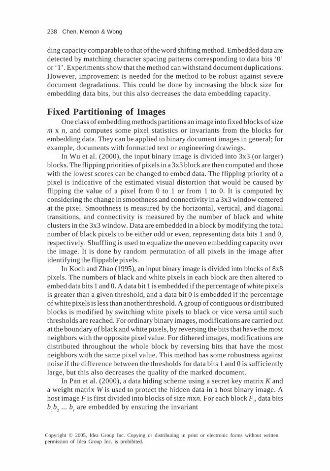
238 Chen, Memon & Wong
Copyright © 2005, Idea Group Inc. Copying or distributing in print or electronic forms without writtenpermission of Idea Group Inc. is prohibited.
ding capacity comparable to that of the word shifting method. Embedded data aredetected by matching character spacing patterns corresponding to data bits ‘0’or ‘1’. Experiments show that the method can withstand document duplications.However, improvement is needed for the method to be robust against severedocument degradations. This could be done by increasing the block size forembedding data bits, but this also decreases the data embedding capacity.
Fixed Partitioning of ImagesOne class of embedding methods partitions an image into fixed blocks of size
m x n, and computes some pixel statistics or invariants from the blocks forembedding data. They can be applied to binary document images in general; forexample, documents with formatted text or engineering drawings.
In Wu et al. (2000), the input binary image is divided into 3x3 (or larger)blocks. The flipping priorities of pixels in a 3x3 block are then computed and thosewith the lowest scores can be changed to embed data. The flipping priority of apixel is indicative of the estimated visual distortion that would be caused byflipping the value of a pixel from 0 to 1 or from 1 to 0. It is computed byconsidering the change in smoothness and connectivity in a 3x3 window centeredat the pixel. Smoothness is measured by the horizontal, vertical, and diagonaltransitions, and connectivity is measured by the number of black and whiteclusters in the 3x3 window. Data are embedded in a block by modifying the totalnumber of black pixels to be either odd or even, representing data bits 1 and 0,respectively. Shuffling is used to equalize the uneven embedding capacity overthe image. It is done by random permutation of all pixels in the image afteridentifying the flippable pixels.
In Koch and Zhao (1995), an input binary image is divided into blocks of 8x8pixels. The numbers of black and white pixels in each block are then altered toembed data bits 1 and 0. A data bit 1 is embedded if the percentage of white pixelsis greater than a given threshold, and a data bit 0 is embedded if the percentageof white pixels is less than another threshold. A group of contiguous or distributedblocks is modified by switching white pixels to black or vice versa until suchthresholds are reached. For ordinary binary images, modifications are carried outat the boundary of black and white pixels, by reversing the bits that have the mostneighbors with the opposite pixel value. For dithered images, modifications aredistributed throughout the whole block by reversing bits that have the mostneighbors with the same pixel value. This method has some robustness againstnoise if the difference between the thresholds for data bits 1 and 0 is sufficientlylarge, but this also decreases the quality of the marked document.
In Pan et al. (2000), a data hiding scheme using a secret key matrix K anda weight matrix W is used to protect the hidden data in a host binary image. Ahost image F is first divided into blocks of size mxn. For each block F
i, data bits
b1b
2 ... b
r are embedded by ensuring the invariant

Data Hiding in Document Images 239
Copyright © 2005, Idea Group Inc. Copying or distributing in print or electronic forms without writtenpermission of Idea Group Inc. is prohibited.
)2(mod...))(( 21r
ri bbbWKFSUM ≡⊗⊕ ,
where ⊕ represents the bit-wise exclusive OR operation, ⊗ represents pair-wisemultiplication, and SUM is the sum of all elements in a matrix. Embedded datacan be easily extracted by computing:
)2)(mod)(( ri WKFSUM ⊗⊕
The scheme can hide as many as )1(log2 +mn bits of data in each image block
by changing at most two bits in the image block. It provides high security, as longas the block size (m x n) is reasonably large. In a 256x256 test image divided intoblocks of size 4x4, 16,384 bits of information were embedded. This methoddoes not provide any measure to ensure good visual quality in the markeddocument.
In Tseng and Pan (2000), an enhancement was made to the methodproposed in Pan et al. (2000) by imposing the constraint that every bit that is tobe modified in a block is adjacent to another bit that has the opposite value. Thisimproves the visual quality of the marked image by making the inserted bits lessvisible, at the expense of sacrificing some data hiding capacity. The new scheme
can hide up to 1)1(log2 −+mn bits of data in an mxn image by changing at most
two bits in the image block.
Boundary ModificationsIn Mei et al. (2001), the data are embedded in the eight-connected boundary
of a character. A fixed set of pairs of five-pixel long boundary patterns were usedfor embedding data. One of the patterns in a pair requires deletion of the centerforeground pixel, whereas the other requires the addition of a foreground pixel.A unique property of the proposed method is that the two patterns in each pairare dual of each other — changing the pixel value of one pattern at the centerposition would result in the other. This property allows easy detection of theembedded data without referring to the original document, and without using anyspecial enforcing techniques for detecting embedded data. Experimental resultsshowed that the method is capable of embedding about 5.69 bits of data percharacter (or connected component) in a full page of text digitized at 300 dpi. Themethod can be applied to general document images with connected components;for example, text documents or engineering drawings.

240 Chen, Memon & Wong
Copyright © 2005, Idea Group Inc. Copying or distributing in print or electronic forms without writtenpermission of Idea Group Inc. is prohibited.
Modifications of Character FeaturesThis class of techniques extracts local features from text characters.
Alterations are then made to the character features to embed data.In Amamo and Misaki (1999), text areas in an image are identified first by
connected component analysis, and are grouped according to spatial closeness.Each group has a bounding box that is divided into four partitions. The fourpartitions are divided into two sets. The average width of the horizontal strokesof characters is computed as feature. To compute average stroke width, verticalblack runs with lengths less than a threshold are selected and averaged. Twooperations — “make fat” and “make thin” — are defined by increasing anddecreasing the lengths of the selected runs, respectively. To embed a “1” bit, the“make fat” operation is applied to partitions belonging to set 1, and the “makethin” operation is applied to partitions belongs to set 2. The opposite operationsare used to embed “0” bit. In the detection process, detection of text linebounding boxes, partitioning, and grouping are performed. The stroke widthfeatures are extracted from the partitions, and added up for each set. If thedifference of the sum totals is larger than a positive threshold, the detectionprocess outputs 1. If the difference is less than a negative threshold, it outputs0. This method could survive the distortions caused by print-and-scan (re-digitization) processes. The method’s robustness to photocopying needs to befurthered investigated.
In Bhattacharjya and Ancin (1999), a scheme is presented to embed secretmessages in the scanned grayscale image of a document. Small sub-character-sized regions that consist of pixels that meet criteria of text-character parts areidentified first, and the lightness of these regions are modulated to embed data.The method employs two scans of the document — a low resolution scan and ahigh resolution scan. The low-resolution scan is used to identify the variouscomponents of the document and establish a coordinate system based on theparagraphs, lines and words found in the document. A list of sites for embeddingdata is selected from the low resolution scanned image. Two site selectionmethods were presented in the paper. In the first method, a text paragraph ispartitioned into grids of 3x3 pixels. Grid cells that contain predominately text-typepixels are selected. In the second method, characters with long strokes areidentified. Sites are selected at locations along the stroke. The second scan is afull-resolution scan that is used to generate the document copy. The pixels fromthe site lists generated in the low-resolution scan are identified and modulated bythe data bits to be embedded. Two or more candidate sites are required forembedding each bit. For example, if the difference between the averageluminance of the pixels belonging to the current site and the next one is positive,the bit is a 1; else, the bit is a 0. For robustness, the data to be embedded are firstcoded using an error correcting code. The resulting bits are then scrambled and

Data Hiding in Document Images 241
Copyright © 2005, Idea Group Inc. Copying or distributing in print or electronic forms without writtenpermission of Idea Group Inc. is prohibited.
dispersed uniformly across the document page. For data retrieval, the averageluminance for the pixels in each site is computed and the data are retrievedaccording to the embedding scheme and the input site list. This method wasclaimed to be robust against printing and scanning. However, this methodrequires that the scanned grayscale image of a document be available. The datahiding capacity of this method depends on the number of sites available on theimage, and in some cases, there might not be enough sites available to embedlarge messages.
Modification of Run-LengthIn Matsui and Tanaka (1994), a method was proposed to embed data in the
run-lengths of facsimile images. A facsimile document contains 1,728 pixels ineach horizontal scan line. Each run length of black (or foreground) pixels is codedusing modified Huffman coding scheme according to the statistical distributionof run-lengths. In the proposed method, each run length of black pixels isshortened or lengthened by one pixel according to a sequence of signature bits.The signature bits are embedded at the boundary of the run lengths according tosome pre-defined rules.
Modifications of Half-Toned ImagesSeveral watermarking techniques have been developed for half-tone im-
ages that can be found routinely in printed matters such as books, magazines,newspapers, printer outputs, and so forth. This class of methods can only be usedfor half-tone images, and are not suitable for other types of document images.The methods described in Baharav and Shaked (1999) and Wang (2001) embeddata during the half-toning process. This requires the original grayscale image.The methods described in Koch and Zhao (1995) and Fu and Au (2000a, 2000b,2001) embed data directly into the half-tone images after they have beengenerated. The original grayscale image is therefore not required.
In Baharav and Shaked (1999), a sequence of two different dither matrices(instead of one) was used in the half-toning process to encode the watermarkinformation. The order in which the two matrices are applied is the binaryrepresentation of the watermark. In Knox (United States Patent) and Wang(United States Patent), two screens were used to form two halftone images anddata were embedded through the correlations between the two screens.
In Fu and Au (2000a, 2000b), three methods were proposed to embeddeddata at pseudo-random locations in half-tone images without knowledge of theoriginal multi-tone image and the half-toning method. The three methods, namedDHST, DHPT, and DHSPT, use one half-tone pixel to store one data bit. InDHST, N data bits are hidden at N pseudo-random locations by forced toggling.That is, when the original half-tone pixel at the pseudo-random locations differs

242 Chen, Memon & Wong
Copyright © 2005, Idea Group Inc. Copying or distributing in print or electronic forms without writtenpermission of Idea Group Inc. is prohibited.
from the desired value, it is forced to toggle. This method results in undesirableclusters of white or black pixels. In the detection process, the data are simplyread from the N pseudo-random locations. In DHPT, a pair of white and blackpixels (instead of one in DHST) is chosen to toggle at the pseudo-randomlocations. This improves over DHST by preserving local intensity and reducingthe number of undesirable clusters of white or black pixels. DHSPT improvesupon DHPT by choosing pairs of white and black pixels that are maximallyconnected with neighboring pixels before toggling. The chosen maximallyconnected pixels will become least connected after toggling and the resultingclusters will be smaller, thus improving visual quality.
In Fu and Au (2001), an algorithm called intensity selection (IS) isproposed to select the best location, out of a set of candidate locations, for theapplication of the DHST, DHPT and DHSPT algorithms. By doing so, significantimprovement in visual quality can be obtained in the output images withoutsacrificing data hiding capacity. In general, the algorithm chooses pixel locationsthat are either very bright or very dark. It represents a data bit as the parity ofthe sum of the half-tone pixels at M pseudo-random locations and selects the bestout of the M possible locations. This algorithm, however, requires the originalgrayscale image or computation of the inverse-half-toned image.
In Wang (2001), two data hiding techniques for digital half-tone imageswere described: modified ordered dithering and modified multiscale errordiffusion. In the first method, one of the 16 neighboring pixels used in thedithering process is replaced in an ordered or pre-programmed manner. Themethod was claimed to be similar to replacing the insignificant one or two bits ofa grayscale image, and is capable of embedding 4,096 bits in an image of size 256x 256 pixels. The second method is a modification of the multi-scale errordiffusion (MSED) algorithm for half-toning as proposed in Katsavounidis andKuo (97), which alters the binarization sequence of the error diffusion processbased on the global and local properties of intensity in the input image. Themodified algorithm uses fewer floors (e.g., three or four) in the image pyramidand displays the binarization sequence in a more uniform and progressive way.After 50% of binarization is completed, the other 50% is used for encoding thehidden data. It is feasible that edge information can be retained with this method.
Kacker and Allebach propose a joint halftoning and watermarking approach(Kacker & Allebach, 2003), that combines optimization based halftoning with aspread spectrum robust watermark. The method uses a joint metric to accountfor the distortion between a continuous tone and a halftone (FWMSE), as wellas a watermark detectability criterion (correlation). The direct binary searchmethod (Allebach et al., 1994) is used for searching a halftone that minimizes themetric. This method is obviously extendable in that other distortion metric and/or watermarking algorithms can be used.
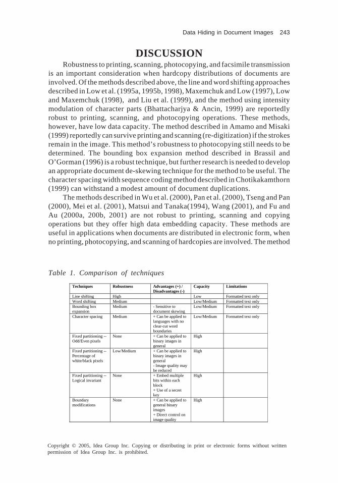
Data Hiding in Document Images 243
Copyright © 2005, Idea Group Inc. Copying or distributing in print or electronic forms without writtenpermission of Idea Group Inc. is prohibited.
DISCUSSIONRobustness to printing, scanning, photocopying, and facsimile transmission
is an important consideration when hardcopy distributions of documents areinvolved. Of the methods described above, the line and word shifting approachesdescribed in Low et al. (1995a, 1995b, 1998), Maxemchuk and Low (1997), Lowand Maxemchuk (1998), and Liu et al. (1999), and the method using intensitymodulation of character parts (Bhattacharjya & Ancin, 1999) are reportedlyrobust to printing, scanning, and photocopying operations. These methods,however, have low data capacity. The method described in Amamo and Misaki(1999) reportedly can survive printing and scanning (re-digitization) if the strokesremain in the image. This method’s robustness to photocopying still needs to bedetermined. The bounding box expansion method described in Brassil andO’Gorman (1996) is a robust technique, but further research is needed to developan appropriate document de-skewing technique for the method to be useful. Thecharacter spacing width sequence coding method described in Chotikakamthorn(1999) can withstand a modest amount of document duplications.
The methods described in Wu et al. (2000), Pan et al. (2000), Tseng and Pan(2000), Mei et al. (2001), Matsui and Tanaka(1994), Wang (2001), and Fu andAu (2000a, 200b, 2001) are not robust to printing, scanning and copyingoperations but they offer high data embedding capacity. These methods areuseful in applications when documents are distributed in electronic form, whenno printing, photocopying, and scanning of hardcopies are involved. The method
Table 1. Comparison of techniques
Techniques Robustness Advantages (+) / Disadvantages (-)
Capacity Limitations
Line shifting High Low Formatted text only Word shifting Medium Low/Medium Formatted text only Bounding box expansion
Medium - Sensitive to document skewing
Low/Medium Formatted text only
Character spacing Medium + Can be applied to languages with no clear-cut word boundaries
Low/Medium Formatted text only
Fixed partitioning -- Odd/Even pixels
None + Can be applied to binary images in general
High
Fixed partitioning -- Percentage of white/black pixels
Low/Medium + Can be applied to binary images in general - Image quality may be reduced
High
Fixed partitioning -- Logical invariant
None + Embed multiple bits within each block + Use of a secret key
High
Boundary modifications
None + Can be applied to general binary images + Direct control on image quality
High

244 Chen, Memon & Wong
Copyright © 2005, Idea Group Inc. Copying or distributing in print or electronic forms without writtenpermission of Idea Group Inc. is prohibited.
in Koch and Zhao (1995) also has high embedding capacity. It offers someamount of robustness if the two thresholds are chosen sufficiently apart, but thisalso decreases image quality.
Methods based on character feature modifications require reliable extrac-tion of the features. For example, the methods described in Amamo and Misaki(1999) and one of the two site-selection methods presented in Bhattacharjya andAnci (1999) require reliable extraction of character strokes. The boundarymodification method presented in Mei et al. (2001) traces the boundary of acharacter (or connected-component), which can always be reliably extracted inbinary images. This method also provides direct and good image quality control.The method described in Matsui and Tanaka (1994) was originally developed forfacsimile images, but could be applied to regular binary document images. Theresulting image quality, however, may be reduced.
A comparison of the above methods shows that there is a trade off betweenembedding capacity and robustness. Data embedding capacity tends to decreasewith increased robustness. We also observed that for a method to be robust, datamust be embedded based on computing some statistics over a reasonably largeset of pixels, preferably spread out over a large region, instead of based on theexact locations of some specific pixels. For example, in the line shifting method,data are embedded by computing centroid position from a horizontal line of textpixels, whereas in the boundary modification method, data are embedded basedon specific configurations of a few boundary pixel patterns.
In addition to robustness and capacity, another important characteristic ofa data hiding technique is its “security” from a steganographic point of view. Thatis, whether documents that contain an embedded message can be distinguishedfrom documents that do not contain any message. Unfortunately, this aspect hasnot been investigated in the literature. However, for any of the above techniquesto be useful in a covert communication application, the ability of a technique to
Techniques Robustness Advantages (+) / Disadvantages (-)
Capacity Limitations
Modification of horizontal stroke widths
Medium Low/Medium Languages rich in horizontal strokes only
Intensity modulations of sub-character regions
Medium Medium Grayscale images of scanned documents only
Run-length modifications
None - Image quality may be reduced
High
Use two-dithering matrices
None Half-tone images only
Embed data at pseudo-random locations
None High Half-tone images only
Modified ordered dithering
None High Half -tone images only
Modified error diffusion
None High Half-tone images only
Table 1. Comparison of techniques (continued)
Data Hiding in Document Images 245
Copyright © 2005, Idea Group Inc. Copying or distributing in print or electronic forms without writtenpermission of Idea Group Inc. is prohibited.
be indistinguishable is quite critical. For example, a marked document createdusing line and word shifting can easily be spotted as it has characteristics that arenot expected to be found in “normal” documents. The block-based techniquesand boundary-based technique presented in the second section may producemarked documents that are distinguishable if they introduce too many irregulari-ties or artifacts. This needs to be further investigated. A similar comment appliesto the techniques presented in the second section. In general, it appears that thedevelopment of “secure” steganography techniques for binary documents hasnot received enough attention in the research community and much work remainsto be done in this area.
Table 1 summarizes the different methods in terms of embedding tech-niques, robustness, advantages/disadvantages, data embedding capacity, andlimitations. Robustness here refers to robustness to printing, photocopying,scanning, and facsimile transmission.
CONCLUSIONSWe have presented an overview and summary of recent developments in
binary document image watermarking and data hiding research. Although therehas been little work done on this topic until recent years, we are seeing a growingnumber of papers proposing a variety of new techniques and ideas. Research onbinary document watermarking and data hiding is still not as mature as for colorand grayscale images. More effort is needed to address this important topic.Future research should aim at finding methods that offer robustness to printing,scanning, and copying, yet provide good data embedding capacity. Quantitativemethods should also be developed to evaluate the quality of marked images. Thesteganographic capability of different techniques needs to be investigated andtechniques that can be used in covert communication applications need to bedeveloped.
REFERENCESAllebach, J.P., Flohr, T.J., Hilgenberg, D.P., & Atkins, C.B. (1994, May).
Model-based halftoning via direct binary search. Proceedings of IS&T’s47th Annual Conference, (pp. 476-482), Rochester, NY.
Amamo, T., & Misaki, D. (1999). Feature calibration method for watermarkingof document images. Proceedings of 5th Int’l Conf on DocumentAnalysis and Recognition, (pp. 91-94), Bangalore, India.
Baharav, Z., & Shaked, D. (1999, January). Watermarking of dither half-tonedimages. Proc. of SPIE Security and Watermarking of MultimediaContents, 1,307-313.
246 Chen, Memon & Wong
Copyright © 2005, Idea Group Inc. Copying or distributing in print or electronic forms without writtenpermission of Idea Group Inc. is prohibited.
Bhattacharjya, A.K., & Ancin, H. (1999). Data embedding in text for a copiersystem. Proceedings of IEEE International Conference on ImageProcessing, 2, 245-249.
Brassil, J., & O’Gorman, L. (1996, May). Watermarking document images withbounding box expansion. Proceedings of 1st Int’l Workshop on Informa-tion Hiding, (pp. 227-235). Newton Institute, Cambridge, UK.
Chotikakamthorn, N. (1999). Document image data hiding techniques usingcharacter spacing width sequence coding. Proc. IEEE Intl. Conf. ImageProcessing, Japan.
Cox, I., Kilian, J., Leighton, T., & Shamoon, T. (1996, May/June). Secure spreadspectrum watermarking for multimedia. In R. Anderson (Ed.), Proc. FirstInt. Workshop Information Hiding (pp. 183-206). Cambridge, UK:Springer-Verlag.
Craver, S., Memon, N., Yeo, B., & Yeung, M. (1998, May). Resolving rightfulownership with invisible watermarking techniques: Limitations, attacks,and implications. IEEE Journal on Selected Areas in Communications,16(4), 573-586.
Digimarc Corporation. http://www.digimarc.com.Foley, J.D., Van Dam, A., Feiner, S.K., & Hughes, J.F. (1990). Computer
graphics: Principles and practice (2nd ed.). Addison-Wesley.Fu, M.S., & Au, O.C. (2000a, January). Data hiding for halftone images. Proc
of SPIE Conf. On Security and Watermarking of Multimedia ContentsII, 3971, 228-236.
Fu, M.S., & Au, O.C. (2000b, June 5-9). Data hiding by smart pair toggling forhalftone images. Proc. of IEEE Int’l Conf. Acoustics, Speech, andSignal Processing, 4, (pp. 2318-2321).
Fu, M.S., & Au, O.C. (2001). Improved halftone image data hiding with intensityselection. Proc. IEEE International Symposium on Circuits and Sys-tems, 5, 243-246.
Holliman, M., & Memon, N. (2000, March). Counterfeiting attacks and blockwiseindependent watermarking techniques. IEEE Transactions on ImageProcessing, 9(3), 432-441.
Kacker, D., & Allebach, J.P. (2003, April). Joint halftoning and watermarking.IEEE Trans. Signal Processing, 51, 1054-1068.
Katsavounidis, I., & Jay Kuo, C.C. (1997, March). A multiscale error diffusiontechnique for digital half–toning. IEEE Trans. on Image Processing, 6(3),483-490.
Knox, K.T. Digital watermarking using stochastic screen patterns, UnitedStates Patent Number 5,734,752.
Koch, E., & Zhao, J. (1995, August). Embedding robust labels into images forcopyright protection. Proc. International Congress on IntellectualProperty Rights for Specialized Information, Knowledge & New Tech-nologies, Vienna.
Data Hiding in Document Images 247
Copyright © 2005, Idea Group Inc. Copying or distributing in print or electronic forms without writtenpermission of Idea Group Inc. is prohibited.
Liu, Y., Mant, J., Wong, E., & Low, S.H. (1999, January).Marking and detectionof text documents using transform-domain techniques. Proc. SPIE Conf.on Security and Watermarking of Multimedia Contents, (pp. 317-328),San Jose, CA.
Low, S.H., Lapone, A.M., & Maxmchuk, N.F. (1995, November 13-17).Document identification to discourage illicit copying. IEEE GlobeCom 95,Singapore.
Low, S.H., & Maxemchuk, N.F. (1998, May). Performance comparison of twotext marking methods. IEEE Journal on Selected Areas in Communica-tions, 16(4).
Low, S.H., Maxemchuk, N.F., Brassil, J.T., & O’Gorman, L. (1995). Documentmarking and identification using both line and word shifting. Infocom 95.Los Alamitos, CA: IEEE Computer Society Press.
Low, S.H., Maxemchuk, N.F., & Lapone, A.M. (1998, March). Documentidentification for copyright protection using centroid detection. IEEETrans. on Comm., 46(3), 372-83.
Matsui, K. & Tanaka, K. (1994). Video-steganography: How to secretly embeda signature in a picture. Proceedings of IMA Intellectual PropertyProject, 1(1), 187-206.
Maxemchuk, N.F., & Low, S.H. (1997, October). Marking text documents.Proceedings of IEEE Intl Conference on Image Processing.
Mei, Q., Wong, E.K., & Memon, N. (2001, January). Data hiding in binary textdocuments. SPIE Proc Security and Watermarking of MultimediaContents III, San Jose, CA.
Pan, H.-K., Chen, Y.-Y., & Tseng, Y.-C. (2000). A secure data hiding schemefor two-color images. IEEE Symposium on Computers and Communica-tions.
Swanson, M., Kobayashi, M., & Tewfik, A. (1998, June). Multimedia dataembedding and watermarking technologies. IEEE Proceedings, 86(6),1064-1087.
Tseng, Y., & Pan, H. (2000). Secure and invisible data hiding in 2-color images.IEEE Symposium on Computers and Communications.
Wang, H.-C.A. (2001, April 2-4). Data hiding techniques for printed binaryimages. The International Conference on Information Technology:Coding and Computing.
Wang, S.G. Digital watermarking using conjugate halftone screens, UnitedStates Patent Number 5,790,703.
Wu, M., Tang, E., & Liu, B. (2000, July 31-August 2). Data hiding in digital binaryimages. Proc. IEEE Int’l Conf. on Multimedia and Expo, New York.
248 About the Authors
Copyright © 2005, Idea Group Inc. Copying or distributing in print or electronic forms without writtenpermission of Idea Group Inc. is prohibited.
About the Authors
Chun-Shien Lu received a PhD in Electrical Engineering from the NationalCheng-Kung University, Taiwan, ROC (1998). From October 1998 through July2002, he joined the Institute of Information Science, Academia Sinica, Taiwan,as a postdoctoral fellow for his army service. Since August 2002, he has beenan assistant research fellow at the same institute. His current research interestsmainly focus on topics of multimedia and time-frequency analysis of signals andimages (including security, networking and signal processing). Dr. Lu receivedthe paper award of the Image Processing and Pattern Recognition Society ofTaiwan many times for his work on data hiding. He organized and chaired aspecial session on multimedia security in the Second and Third IEEE Pacific-RimConference on Multimedia (2001-2002). He will co-organize two special ses-sions in the Fifth IEEE International Conference on Multimedia and Expo(ICME) (2004). He holds one U.S. and one ROC patent on digital watermarking.He is a member of the IEEE Signal Processing Society and the IEEE Circuits andSystems Society.
* * *
Andrés Garay Acevedo was born in Bogotá, Colombia, where he studiedsystems engineering at the University of Los Andes. After graduation hepursued a Master’s in Communication, Culture and Technology at GeorgetownUniversity, where he worked on topics related to audio watermarking. Otherresearch interests include sound synthesis, algorithmic composition, and musicinformation retrieval. He currently works for the Colombian Embassy inWashington, DC, where he is implementing several projects in the field ofinformation and network security.
Mauro Barni was born in Prato in 1965. He graduated in electronic engineeringat the University of Florence (1991). He received a PhD in Informatics and

About the Authors 249
Copyright © 2005, Idea Group Inc. Copying or distributing in print or electronic forms without writtenpermission of Idea Group Inc. is prohibited.
Telecommunications (October 1995). From 1991 to 1998, he was with theDepartment of Electronic Engineering, University of Florence, Italy, where heworked as a postdoc researcher. Since September 1998, he has been with theDepartment of Information Engineering of the University of Siena, Italy, wherehe works as associate professor. His main interests are in the field of digitalimage processing and computer vision. His research activity is focused on theapplication of image processing techniques to copyright protection and authen-tication of multimedia data (digital watermarking), and on the transmission ofimage and video signals in error-prone, wireless environments. He is author/co-author of more than 150 papers published in international journals and conferenceproceedings. Mauro Barni is member of the IEEE, where he serves as memberof the Multimedia Signal Processing Technical Committee (MMSP-TC). He isassociate editor of the IEEE Transactions on Multimedia.
Franco Bartolini was born in Rome, Italy, in 1965. In 1991, he graduated (cumlaude) in electronic engineering from the University of Florence, Italy. InNovember 1996, he received a PhD in Informatics and Telecommunicationsfrom the University of Florence. Since November 2001, he has been assistantprofessor at the University of Florence. His research interests include digitalimage sequence processing, still and moving image compression, nonlinearfiltering techniques, image protection and authentication (watermarking), imageprocessing applications for the cultural heritage field, signal compression byneural networks, and secure communication protocols. He has published morethan 130 papers on these topics in international journals and conferences. Heholds three Italian and one European patent in the field of digital watermarking.Dr. Bartolini is a member of IEEE, SPIE and IAPR. He is a member of theprogram committee of the SPIE/IST Workshop on Security, Steganography, andWatermarking of Multimedia Contents.
Minya Chen is a PhD student in the Computer Science Department atPolytechnic University, New York (USA). She received her BS in ComputerScience from University of Science and Technology of China, Hefei, China, andreceived her MS in Computer Science from Polytechnic University, New York.Her research interests include document image analysis, watermarking, andpattern recognition, and she has published papers in these areas.
Alessia De Rosa was born in Florence, Italy, in 1972. In 1998, she graduatedin electronic engineering from the University of Florence, Italy. In February2002, she received a PhD in Informatics and Telecommunications from theUniversity of Florence. At present, she is involved in the research activities ofthe Image Processing and Communications Laboratory of the Department ofElectronic and Telecommunications of the University of Florence, where sheworks as a postdoc researcher. Her main research interests are in the fields of
250 About the Authors
Copyright © 2005, Idea Group Inc. Copying or distributing in print or electronic forms without writtenpermission of Idea Group Inc. is prohibited.
digital watermarking, human perception models for digital image watermarkingand quality assessment, and image processing for cultural heritage applications.She holds an Italian patent in the field of digital watermarking.
Jana Dittmann was born in Dessau, Germany. She studied Computer Scienceand Economy at the Technical University in Darmstadt. In 1999, she receivedher PhD from the Technical University of Darmstadt. She has been a fullprofessor in the field of multimedia and security at the University of Otto-von-Guericke University Magdeburg since September 2002. Dr. Dittmann special-izes in the field of Multimedia Security. Her research is mainly focused on digitalwatermarking and content-based digital signatures for data authentication andfor copyright protection. She has many national and international publications, isa member of several conference PCs, and organizes workshops and confer-ences in the field of multimedia and security issues. She was involved in all of thelast five Multimedia and Security Workshops at ACM Multimedia and she hasinitiated this workshop as a standalone ACM event since 2004. In 2001, she wasa co-chair of the CMS2001 conference that took place in May 2002 inDarmstadt, Germany. She is an associate editor for the ACM MultimediaSystems Journal and a guest editor for the IEEE Transaction on SignalProcessing Journal for Secure Media. Dr. Dittmann is a member of the ACMand GI Informatik.
Chang-Tsun Li received a BS in Electrical Engineering from the Chung ChengInstitute of Technology (CCIT), National Defense University, Taiwan (1987), anMS in Computer Science from the U.S. Naval Postgraduate School (1992), anda PhD in Computer Science from the University of Warwick, UK (1998). Hewas an associate professor during 1999-2002 in the Department of ElectricalEngineering at CCIT and a visiting professor in the Department of ComputerScience at the U.S. Naval Postgraduate School in the second half of 2001. Heis currently a lecturer in the Department of Computer Science at the Universityof Warwick. His research interests include image processing, pattern recogni-tion, computer vision, multimedia security, and content-based image retrieval.
Ching-Yung Lin received his PhD from Columbia University. Since 2000, hehas been a research staff member in the IBM T.J. Watson Research Center(USA). His current research interests include multimedia understanding andmultimedia security. Dr. Lin has pioneered the design of video/image contentauthentication systems. His IBM multimedia semantic mining project teamperforms best in the NIST TREC video semantic concept detectionbenchingmarking in 2002 and 2003. Dr. Lin has led a semantic annotation project,which involves 23 worldwide research institutes, since 2003. He is a guest editorof the Proceedings of IEEE, technical program chair of IEEE ITRE 2003, andchair of Watson Workshop on Multimedia 2003. Dr. Lin received the 2003 IEEE
About the Authors 251
Copyright © 2005, Idea Group Inc. Copying or distributing in print or electronic forms without writtenpermission of Idea Group Inc. is prohibited.
Circuits and Systems Society Outstanding Young Author award, and is anaffiliate assistant professor at the University of Washington.
Jiang-Lung Liu received a BS (1988) and a PhD (2002), both in ElectricalEngineering, from the Chung Cheng Institute of Technology (CCIT), NationalDefense University, Taiwan. He is currently an assistant professor in theDepartment of Electrical Engineering at CCIT. His research interests includecryptology, steganography, multimedia security, and image processing.
Der-Chyuan Lou received a PhD (1997) from the Department of ComputerScience and Information Engineering at National Chung Cheng University,Taiwan, ROC. Since 1987, he has been with the Department of ElectricalEngineering at Chung Cheng Institute of Technology, National Defense Univer-sity, Taiwan, ROC, where he is currently a professor and a vice chairman. Hisresearch interests include cryptography, steganography, algorithm design andanalysis, computer arithmetic, and parallel and distributed systems. ProfessorLou is currently area editor for Security Technology of Elsevier Science’sJournal of Systems and Software. He is an honorary member of the Phi TauPhi Scholastic Honor Society. He has been selected and included in the 15th and18th editions of Who’s Who in the World, published in 1998 and 2001,respectively.
Nasir Memon is an associate professor in the Computer Science Departmentat Polytechnic University, New York (USA). He received his BE in ChemicalEngineering and MSc in Mathematics from the Birla Institute of Technology,Pilani, India, and received his MS and PhD in Computer Science from theUniversity of Nebraska. His research interests include data compression,computer and network security, multimedia data security and multimedia com-munications. He has published more than 150 articles in journals andconference proceedings. He was an associate editor for IEEE Transactions onImage Processing from 1999 to 2002 and is currently an associate editor for theACM Multimedia Systems Journal and the Journal of Electronic Imaging.He received the Jacobs Excellence in Education award in 2002.
Martin Steinebach is a research assistant at Fraunhofer IPSI (IntegratedPublication and Information Systems Institute). His main research topic is digitalaudio watermarking. He studied computer science at the Technical Universityof Darmstadt and finished his diploma thesis on copyright protection for digitalaudio in 1999. Martin Steinebach had the organizing committee chair of CMS2001 and co-organizes the Watermarking Quality Evaluation Special Session atITCC International Conference on Information Technology: Coding andComputing 2002. Since 2002 he has been the head of the department MERIT
252 About the Authors
Copyright © 2005, Idea Group Inc. Copying or distributing in print or electronic forms without writtenpermission of Idea Group Inc. is prohibited.
(Media Security in IT) and of the C4M Competence Centre for MediaSecurity.
Mohamed Abdulla Suhail received his PhD from the University of Bradford(UK), School of Informatics in Digital Watermarking for Multimedia CopyrightProtection. Currently, he is working as a project manager for IT and telecommu-nications projects in an international development bank. Having worked forseveral years in project management, Dr. Suhail retains close links with theindustry. He has spoken at conferences and guest seminars worldwide and isknown for his research work in the area of information systems and digitalwatermarking. He has published more than 16 papers in international refereedjournals and conferences. He also contributed to two books published byinternational publishers. Dr. Suhail has received several awards from differentacademic organizations.
Qi Tian is a principal scientist in the Media Division, Institute for InfocommResearch (I2R), Singapore. His main research interests include image/video/audio analysis, indexing and retrieval, media content identification and security,computer vision, and pattern recognition. He received a BS and an MS from theTsinghua University in China, and a PhD from the University of South Carolina(USA). All of these degrees were in electrical and computer engineering. He isan IEEE senior member and has served on editorial boards of internationaljournals and as chairs and members of technical committees of internationalconferences on multimedia.
Edward K. Wong received his BE from the State University of New York atStony Brook, his ScM from Brown University, and his PhD from PurdueUniversity, all in Electrical Engineering. He is currently associate professor inthe Department of Computer and Information Science at Polytechnic University,Brooklyn, New York (USA). His current research interests include content-based image/video retrieval, document image analysis and watermarking, andpattern recognition. He has published extensively in these areas, and his researchhas been funded by federal and state agencies, as well as private industries.
Changsheng Xu received his PhD from Tsinghua University, China (1996).From 1996 to 1998, he was a research associate professor in the National Labof Pattern Recognition, Institute of Automation, Chinese Academy of Sciences.He joined the Institute for Infocomm Research (I2R) of Singapore in March1998. Currently, he is a senior scientist and head of the Media Adaptation Labat I2R. His research interests include digital watermarking, multimedia process-ing and analysis, computer vision and pattern recognition. He is an IEEE seniormember.
Index 253
Copyright © 2005, Idea Group Inc. Copying or distributing in print or electronic forms without writtenpermission of Idea Group Inc. is prohibited.
Index
A
active fingerprinting 161amplitude modification 89audio restoration attack 101audio watermarking 75, 164authentication 233
B
bit error rate (BER) 100, 129bit rate 129bitstream watermarks 85Boneh-Shaw fingerprint scheme 161boundary modifications 239broadcast monitoring 86
C
character features 240character shifting 236coalition attack secure fingerprinting
158collusion attack 103collusion secure fingerprinting 158compressed domain watermarking 147computational complexity 130
content authentication 87contrast masking 54contrast masking model 50contrast sensitivity function 50copy prevention 233copyright owner identification 86copyright protection 3covert communication 88customer identification 158
D
data hiding 48, 231digital data 2digital images 182digital intellectual property 2digital rights management (DRM) 128,
234digital signal quality 2digital signature-based image authenti-
cation 207digital watermarking 1, 162, 232digital watermarking application 7Dither watermarking 90

254 Index
Copyright © 2005, Idea Group Inc. Copying or distributing in print or electronic forms without writtenpermission of Idea Group Inc. is prohibited.
E
e-commerce 1e-fulfillment 3e-operations 3e-tailing 3echo hiding 136
F
false positive rate (FPR) 106fingerprinting 85, 233fragile watermarks 85
H
half-toned images 241head related transfer function 107human auditory system (HAS) 107,
130human visual system (HVS) 50, 207
I
image authentication 173information systems (IS) 2intellectual property 1invertibility attack 101invisible watermarks 6iso-frequency masking 55
J
just noticeable contrast (JNC) 52
L
labeling-based techniques 208low bit coding 132
M
mask building 65masking 54media signals 1metadata binding 234multimedia authentication system 176music industry 76
N
non-iso-frequency masking 57non-strict authentication 214
O
ownership assertion 233
P
PCM audio 132perceptible watermarks 85perceptual audio quality measure
(PAQM) 128perceptual masking 137perceptual phenomena 108phase coding 133proof of ownership 87
R
robust digital signature 179robust watermarking scheme 14robust watermarks 85run-length 241
S
Schwenk fingerprint scheme 161secret keys 84security 14, 130signal diminishment attacks 103signal processing operations 104signal-to-noise ratio (SNR) 128spread spectrum coding 134steganography 4, 232still images 48strict authentication 210
T
transactional watermarks 87
V
video watermarking 165visible watermarks 6
Index 255
Copyright © 2005, Idea Group Inc. Copying or distributing in print or electronic forms without writtenpermission of Idea Group Inc. is prohibited.
W
watermark embedding 8, 60watermark extraction scheme 146watermarking 77, 182watermarking algorithms 163watermarking classification 7

BO O K CH A P T E R S
JO U R N A L ART I C L E S
CO N F E R E N C E PR O C E E D I N G S
CA S E ST U D I E S
The InfoSci-Online database is the
most comprehensive collection of
full-text literature published by
Idea Group, Inc. in:
n Distance Learning
n Knowledge Management
n Global Information Technology
n Data Mining & Warehousing
n E-Commerce & E-Government
n IT Engineering & Modeling
n Human Side of IT
n Multimedia Networking
n IT Virtual Organizations
BENEFITS
n Instant Access
n Full-Text
n Affordable
n Continuously Updated
n Advanced Searching Capabilities
The Bottom Line: With easyto use access to solid, currentand in-demand information,InfoSci-Online, reasonablypriced, is recommended foracademic libraries.
- Excerpted with permission from Library Journal, July 2003 Issue, Page 140
“
”
Start exploring atwww.infosci-online.com
Recommend to your Library Today!
Complimentary 30-Day Trial Access Available!
InfoSci-Online
Instant access to the latest offerings of Idea Group, Inc. in the fields of
INFORMATION SCIENCE, TECHNOLOGY AND MANAGEMENT!
DatabaseInfoSci-OnlineDatabase
A product of:
Information Science Publishing*Enhancing knowledge through information science
*A company of Idea Group, Inc.www.idea-group.com

BROADEN YOUR IT COLLECTION
WITH IGP JOURNALS
[email protected] www. i d e a - g r o u p . c o m
A company of Idea Group Inc.
701 East Chocolate Avenue, Hershey, PA 17033-1240, USATel: 717-533-8845; 866-342-6657 • 717-533-8661 (fax)
Visit the IGI website for more information onthese journals at www.idea-group.com/journals/
Name:____________________________________ Affiliation: __________________________
Address: ______________________________________________________________________
_____________________________________________________________________________
E-mail:______________________________________ Fax: _____________________________
Upcoming IGP JournalsJanuary 2005
o Int. Journal of Data Warehousing & Mining o Int. Journal of Enterprise Information Systems
o Int. Journal of Business Data Comm. & Networking o Int. Journal of Intelligent Information Technologies
o International Journal of Cases on E-Commerce o Int. Journal of Knowledge Management
o International Journal of E-Business Research o Int. Journal of Mobile Computing & Commerce
o International Journal of E-Collaboration o Int. Journal of Technology & Human Interaction
o Int. Journal of Electronic Government Research o International Journal of Virtual Universities
o Int. Journal of Info. & Comm. Technology Education o Int. J. of Web-Based Learning & Teaching Tech.’s
Established IGP Journals
o Annals of Cases on Information Technology o International Journal of Web Services Research
o Information Management o Journal of Database Management
o Information Resources Management Journal o Journal of Electronic Commerce in Organizations
o Information Technology Newsletter o Journal of Global Information Management
o Int. Journal of Distance Education Technologies o Journal of Organizational and End User Computing
o Int. Journal of ITStandardsand Standardization Research
is an innovative international publishing company, founded in 1987, special -izing in information science, technology and management books, journalsand teaching cases. As a leading academic/scholarly publisher, IGP is pleasedto announce the introduction of 14 new technology-based research journals,in addition to its existing 11 journals published since 1987, which beganwith its renowned Information Resources Management Journal.
Free Sample Journal CopyShould you be interested in receiving a free sample copy of any of IGP'sexisting or upcoming journals please mark the list below and provide yourmailing information in the space provided, attach a business card, or emailIGP at [email protected].
I d e aG ro u p
P u b l i s h i n g
IDEA GROUP PUBLISHING

An excellent addition to your library
�������������� ����� ������ ���������� �����������
��������������� ��!�"
#��$����%�"�����%""����& ��'���(�!�) �*�������������������++�
ISBN 1-931777-43-8(s/c) • US$59.95 • eISBN 1-931777-59-4• 300 pages • Copyright © 2003
IRM PressHershey • London • Melbourne • Singapore
,��� ���- ������
#���� � ���.
��*��������� ��(
��(�������/ �*����
Rasool Azari, University of Redlands, California, USA
Corporate and individual behaviors are increasinglyscrutinized as reports of scandals around the worldare frequently becoming the subject of attention. Ad-ditionally, the security of data and information andethical problems that arise when enforcing the appro-priate security initiatives are becoming prevalent aswell. Current Security Management & Ethical Is-sues of Information Technology focuses on theseissues and more, at a time when the global societygreatly needs to re-examine the existing policies andpractices.
“Embracing security management programs and including them in the decision makingprocess of policy makers helps to detect and surmount the risks with the use of new andevolving technologies. Raising awareness about the technical problems and educatingand guiding policy makers, educators, managers, and strategists is the responsibility ofcomputer professionals and professional organizations.”
Rasool AzariRasool AzariRasool AzariRasool AzariRasool AzariUniversity of Redlands, CAUniversity of Redlands, CAUniversity of Redlands, CAUniversity of Redlands, CAUniversity of Redlands, CA
An excellent addition to your library
�������������� ����� ������ ���������� ���������
����������������� ��!�"�
#��$����%�"�����%""����& ��'���(�!�) �*�������������������++�
IRM PressHershey • London • Melbourne • Singapore
ISBN 1-931777-41-1 (s/c); eISBN 1-931777-57-8 • US$59.95 • 300 pages • © 2003
“This is a scholarly and academic book that is focused on the latest research andfindings associated with information management in conjunction with supportsystems and multimedia technology. It includes the most recent research and
findings, on a mainstream topic that is impacting such institutions worldwide.”–George Ditsa, University of Wollongong, Australia
��(�������#���� � ��%
,������,��� ���-
#����� ����. �*����
George DitsaUniversity of Wollongong, Australia
There is a growing interest in developing intelligentsystems that would enable users to accomplish complextasks in a web-centric environment with relative easeutilizing such technologies. Additionally, because newmultimedia technology is emerging at an unprecedentedrate, tasks that were not feasible before are becomingtrivial due to the opportunity to communication withanybody at any place and any time. Rapid changes insuch technologies are calling for support to assist indecision-making at all managerial levels withinorganizations. Information Management: SupportSystems & Multimedia Technology strives to addressthese issues and more by offering the most recent researchand findings in the area to assist these managers andpractitioners with their goals.

An excellent addition to your library
It’s Easy to Order! Order online at www.idea-group.com or
call 717/533-8845 x10!
Mon-Fri 8:30 am-5:00 pm (est) or fax 24 hours a day 717/533-8661
Idea Group PublishingHershey • London • Melbourne • Singapore
Multimedia Systems and
Content-Based
Image Retrieval
Edited by: Sagarmay Deb, Ph.D.University of Southern Queensland, Australia
ISBN: 1-59140-156-9; US$79.95 h/c• ISBN: 1-59140-265-4; US$64.95 s/ceISBN: 1-59140-157-7 • 406 pages • Copyright 2004
Multimedia systems and content-based imageretrieval are very important areas of research incomputer technology. Numerous research worksare being done in these fields at present. Thesetwo areas are changing our life-styles becausethey together cover creation, maintenance,accessing and retrieval of video, audio, image,textual and graphic data. But still severalimportant issues in these areas remainunresolved and further research works areneeded to be done for better techniques and applications. Multimedia
Systems and Content-Based Image Retrieval addresses theseunresolved issues and highlights current research.
“Multimedia Systems and Context-Based Image Retrieval contributes to thegeneration of new and better solutions to relevant issues in multi-media-systems andcontent-based image retrieval by encouraging researchers to try new approachesmentioned in the book.”–Sagarmay Deb, University of Southern Queensland, Australia
New Release!


![Interoperable and Unified Multimedia Retrieval]{Interoperable and Unified Multimedia Retrieval in Distributed and Heterogeneous Environments](https://static.documents.pub/doc/80x56/545d3f5ab0af9fb32c8b4e29/interoperable-and-unified-multimedia-retrievalinteroperable-and-unified-multimedia-retrieval-in-distributed-and-heterogeneous-environments.jpg)


