+ All Categories
Home > Documents > MULTIPHYSICS PHENOMENA ANALYSIS ON BOUNDARY LAYER … Educational Notes/STO-EN... · BOUNDARY LAYER...

MULTIPHYSICS PHENOMENA ANALYSIS ON BOUNDARY LAYER … Educational Notes/STO-EN... · BOUNDARY LAYER...

Date post: 25-Aug-2018
Category:
Upload: vuongthuan
View: 221 times
Download: 1 times
Share this document with a friend
20
von Karman Institute for Fluid Dynamics STO-AVT-VKI Lecture Series 2016/17 – AVT 289 Lecture Series on MULTIPHYSICS PHENOMENA ANALYSIS ON BOUNDARY LAYER STABILITY IN HYPERSONIC REGIME September 18-20, 2017 UNSTEADINESS IN TURBULENT SHOCK WAVE BOUNDARY LAYER INTERACTION P. Dupont IUSTI, Aix Marseille University, CNRS, France
Transcript

von Karman Institute for Fluid Dynamics

STO-AVT-VKI Lecture Series 2016/17 – AVT 289

Lecture Series on

MULTIPHYSICS PHENOMENA ANALYSIS ON BOUNDARY LAYER STABILITY IN

HYPERSONIC REGIME

September 18-20, 2017

UNSTEADINESS IN TURBULENT SHOCK WAVE BOUNDARY LAYER INTERACTION

P. Dupont IUSTI, Aix Marseille University, CNRS, France

Unsteadiness in turbulent shock wave boundary layer interaction

Pierre Dupont

IUSTI

Aix Marseille University, CNRS UMR 7343

5 rue Enrico Fermi

Marseille, 13013

France

[email protected]

ABSTRACT

Shock/turbulent boundary-layer interactions produce generally unsteadiness of the shock system. This phe-

nomenon is reviewed and analyzed, by evaluating the results of various experiments and simulations. In partic-

ular, results in the case of a shock reflection are presented. This kind of interaction is characterized by strong

unsteadiness, both at low and medium frequency compared to the energetic scales of the incoming boundary

layer. Some generic schemes are presented to describe the mean and unsteady fields.

Contents

1.0 Introduction 1

2.0 Mean flow properties 2

2.1 General flow organization . . . . . . . . . . . . . . . . . . . . . . . . . . . . . . . . . . . . . 2

2.2 Length of interaction . . . . . . . . . . . . . . . . . . . . . . . . . . . . . . . . . . . . . . . 3

2.3 Separated shear layer . . . . . . . . . . . . . . . . . . . . . . . . . . . . . . . . . . . . . . . 6

2.4 Relaxation region . . . . . . . . . . . . . . . . . . . . . . . . . . . . . . . . . . . . . . . . . 7

3.0 Unsteadiness in the TSWBLI 7

3.1 Shock waves unsteadiness . . . . . . . . . . . . . . . . . . . . . . . . . . . . . . . . . . . . 7

3.2 Interaction region . . . . . . . . . . . . . . . . . . . . . . . . . . . . . . . . . . . . . . . . . 8

3.3 Spatial Links . . . . . . . . . . . . . . . . . . . . . . . . . . . . . . . . . . . . . . . . . . . 9

4.0 Generic schemes for separated TSWBLI 10

1.0 INTRODUCTION

Shock Wave Boundary Layer Interactions (SWBLI) have been widely studied in the last decades (see for ex-

ample the following review papers: [1–6]). The most commonly considered interactions concern those with

STO-AVT-289 - Multiphysics phenomena analysis on boundary layer stability in hypersonic regime 5- 1

Unsteadiness in turbulent shock wave boundary layer interaction

a turbulent boundary layer, although laminar or transitional interactions have also been investigated in litera-

ture. Cases under consideration covered a large range of geometric configurations (among others normal shock

interactions ([7–9]), blunt fin interactions ([10, 11]), over-expanded nozzles ([12, 13]), compression ramp in-

teractions ([14–28]) and incident reflecting shock interactions ([29–41]) ; the list is evidently not exhaustive).

In addition, the considered flow conditions cover a large range of Mach numbers (from transonic to hypersonic

values) and of Reynolds numbers (spanning at least two orders of magnitude depending on the experimental

facilities).

Despite these large variations in aerodynamic and geometric parameters, several general properties have

been highlighted for this family of flows. The qualitative mean organization of the flow is currently quite well

understood, see [1]. Good quantitative agreement has been obtained in the particular case where the shock

strength is large enough for the boundary layer to separate. In those cases, the free interaction theory proposed

by [42] suggests that the separation shock properties become independent of the original cause of the separation

(i.e. the flow deflection angle). Therefore, notwithstanding the difference in flow geometry, the wall pressure

distributions for sufficiently separated shock reflections and compression ramps are nearly coincident (see [1]).

More recently, evidence of low frequency unsteadiness of the separation shock has been reported ([23,

24, 43, 44]). These frequencies are about two orders of magnitude below those of the energetic scales of the

upstream boundary layer and their origin has been a subject of studies for two decades.

Although the precise sources of the separation shock motions are still under debate, it has been shown re-

cently that in separated cases, the low frequency unsteadiness of the separation shock is also rather independent

of the particular geometry of the flow ([27, 30, 45, 46]). For example, a dimensionless frequency of the separa-

tion shock oscillations, originally proposed for a Mach 3 compression ramp case ([23]), can be defined with a

nearly constant value, whatever the particular shock induced separation that is considered (see [23, 45]). This

dimensionless frequency, or Strouhal number, is defined as:

SL =fL

U1

(1)

where f is the characteristic shock motion frequency, L the characteristic length of the interaction (se part. 2.0)

and U1 the velocity downstream the separation shock.

The document is organized as follows. In part 2.0, the mean flow properties will be detailed for the particular

case of a Mach 2.3 shock reflection and a model to describe the length scale of the SWBLI will be presented. In

part 3.0, details about the unsteadiness which are developing inside along the interaction will be given. Some

generic scheme, derived from these results, will be presented in the part 4.0.

2.0 MEAN FLOW PROPERTIES

2.1 General flow organization

The general flow organization is detailed in the particular case of the shock reflection. The global organization

of the incident shock wave boundary layer interaction was obtained by spark Schlieren visualization and PIV

measurements (see figure 1(a) ), for which the flow deviation due to the incident shock is 8◦, and the pressure

gradient is strong enough for the layer to separate.

The PIV processing operate some average over the size of the interrogation window. An assessment of this space

integration can be made as follows. The method implicitly assumes that for all scales, particles are convected

at the local flow velocity. In inhomogeneous conditions, a problem can arise if the velocity fluctuation is

affected by the finite size of the interrogation cell. A criterion was proposed by [47], who assumed that a cell

5- 2 STO-AVT-289 - Multiphysics phenomena analysis on boundary layer stability in hypersonic regime

Unsteadiness in turbulent shock wave boundary layer interaction

is sufficiently small if the velocity variation ΔU over the cell is small compared to the velocity fluctuation, i.e.

ΔU � u′. For a cell of height h, the previous condition, after linearisation leads to:

h∂U

∂y� u′ or h �

u′

∂U/∂y(2)

We recognize in the right hand side member the definition of the mixing length. In the external boundary layer

the mixing length is constant, l � 0.1δ. Therefore, in the external layer, it is possible to derive the simple

criterion:

h � 0.1δ (3)

which gives an indication of an acceptable size of the interrogation window. In these experiments, the spatial

resolution of the PIV measurements were of 50pixel/mm, leading to a longitudinal field of view (FOV) of

32mm. Since the FOV is rather reduced, and to obtain mean quantities along the whole interaction as shown

in Figure 1(a), six different acquisitions, at different longitudinal positions, were necessary to obtain a final

longitudinal FOV of 160mm. The final effective cell size is 0.64 × 0.32mm2, for a boundary layer thickness

of δ = 11mm. Therefore, in the incoming boundary layer, we obtain a ratio h/δ = 0.06 which satisfies the

criteria defined by the relation 3. An overlap of 50 % between cells provided a final field of 138× 505 vectors,

after assembly of the different acquisitions.

The maps of turbulent normal stresses (wall-normal component) is presented and superimposed on Schlieren

snapshots figure 1(a). The levels of velocity fluctuations are found to increase dramatically in the interactions,

and this high level persists over a long distance downstream of the interaction. The main features are highlighted

in figure 1(b) as proposed in [1]. The separation region is assimilated with an isobaric region divided in two

parts:

• the upstream region extends from the separation point to the reflection of the incident shock on the

separated region. This region corresponds to a constant positive deviation angle.

• The downstream region is associated with a constant negative angle in order to ensure the flow reattach-

ment. It yields the creation of an expansion wave. Pressure equilibrium between the isobaric separation

and the supersonic regions is obtained by ensuring that the pressure decrease across the expansion wave

is equal to its increase across the incident shock. Thus, expansion deviates the flow down to the wall at

an angle approximatively equal to the imposed deviation and P2 � P4.

Downstream from the reattachment, an equivalent reattachment shock is required to model the flow deviation

necessary for achieving a wall–parallel streamline. It results in the increase in pressure found downstream from

the interaction. When the interaction is fully separated, the deflection angle imposed by the first ramp becomes

independent of the incident–shock intensity and consequently the pressure ratio at the separation point also

becomes independent. Similar features were found for compression ramps [15], in accordance with the so–

called free interaction theory[42].

2.2 Length of interaction

Shock wave boundary layer interactions (SWBLIs) present large qualitative similarities whatever the aerody-

namic and geometric parameters. Nevertheless, it remains quite difficult to compare the length scales of these

interactions. The characteristic length L represents the effects of the presence of the boundary layer in com-

parison to a purely inviscid flow. It is defined as the observed upstream shift of the shock wave CS due to the

thickening of the boundary layer, subject to the imposed pressure jump (or equivalently the angle of deviation

STO-AVT-289 - Multiphysics phenomena analysis on boundary layer stability in hypersonic regime 5- 3

Unsteadinessinturbulentshockwaveboundarylayerinteraction

(a)

C3

C4C1

ϕ1

ϕ3

ϕ

ϕ

A

B C

C2

1

2

3

4

IH

Hw

ϕ2

χ

D

D

0

Expansionfan

Isobaric region"Dead air"

(b)

Figure1:(a)SchlierenpictureoftheshockboundarylayerinteractioncarriedoutinIUSTI’swindtunnelwithIso-valuesforrmsnormalvelocitysuperimposedonthepictureand(b)Inviscidequivalentscenarioforshock-waveboundarylayerinteractionwithseparation[1].

oftheflow). Whentheboundarylayerissufficientlydeceleratedtoseparate,theshockwaveCSiscalledtheseparationshock.Forsimplicity,wewillkeepthisnomenclatureforthisshockwave,whatevertheseparationstateoftheflow.Hence,inthecaseofreflectingwaves,Lisdefinedasthedistancebetweenthefootoftheseparationshockandthetheextrapolatedwallimpactpointoftheincidentshock(seeFigure1(b)).Similarly,incasesofforexamplecompressioncornersandbluntfins,Lisdefinedasthedistancebetweenthefootoftheseparationshockandthecorner,respectivelytheobstacle.Incaseswithlargeseparation,LcanbeconsideredasaroughestimateofthelengthofseparationLsepwhichispoorlydocumentedinliterature.Ascalinganalysiswasderivedforthetwomaingeometricconfigurations(compressioncornerandshockre-flection)[48].Asastartingpoint,itisassumedthatLissomefunctionF1ofthereferenceflowconditions,seeequation4.

L=F1(Me,Reθ,ϕ,TwTaw,geometry,...) (4)

whereϕistheflowdeviation(thecornerangleforcompressionrampsandthedeviationangleacrosstheincidentshockinflowreflectioncases).Itisnowattemptedtoreformulatetheexpressioninequation4insuchawayastoobtainarelationbetween

anon-dimensionalinteractionlength(L∗)andanon-dimensionalinteractionstrengthparameterthatrepresentsthetendencyoftheflowtoseparate(S∗),inotherwords:

L∗=F2(S∗) (5)

whereF2isastilltobedefinedfunction.Itisproposedtodefinethenon-dimensionalinteractionstrengthparameterS∗as:

S∗=∆P

∆Psep(6)

where∆Psepistheshockintensityneededtomaketheboundarylayertoseparate;(P3−P1)forthereflectionand(P2−P1)forthecompressioncorner,seeFigure2.Todevelopthisreasoningfurther,aninviscidmodelwasdefinedbasedontheintegralformoftheconservationlaws.Thepresenceoftheboundarylayeristakenintoaccountthroughtheintegraloftheupstreamanddown-streamvelocityanddensityprofiles(inotherwords:δ∗andθ).Furthermore,itisassumedthatattheexitplane,

5-4 STO-AVT-289-Multiphysicsphenomenaanalysisonboundarylayerstabilityinhypersonicregime

Unsteadinessinturbulentshockwaveboundarylayerinteraction

ϕβ

cvL

,θ1δ*1

L

2ρ ,U2,V 2

ρ3U,3

ρ1U,1p3

cvH

p1

δ*3,θ3

(a)

,θ1δ*1

βϕ

cvL L

ρ2U,2

ρ1U,1

p2

1

p1

cvH

cvH 2

δ*2,θ2

(b)

Figure2:Controlvolume:(a)incidentshockreflectioncase;(b)compressionrampcase.

thepressurejumpimposedbytheshocksystem(∆P)equalstheinviscidvalue,andthatthefluidisparalleltothewall.Thephysicalcauseoftheinteractionlengthmaynowbeinterpretedasachangeindisplacementthicknessbetweentheupstreamanddownstreamstates,creatingakindof‘equivalent’stepatthewall.Toconcretisetheseideas,acontrolvolumeapproachisdefined,enclosingtheinteractionregion.Itisassumedthattheflowistwodimensionalandsteadyinthemean.Intheformulationoftheinviscidflowmodel,theviscoustermsareinherentlyneglectedwithrespecttothepressureforceandtheinertialtermsinthedeductionofthemomentumconservationbasedformulation.Theflowconditionsonallsidesofthecontrolvolumeareprescribedbythefree-streamconditionsandtheinviscidobliqueshockrelations.Thepresenceoftheboundarylayercanbetakenintoaccountthroughthedefinitionofthedisplacementthickness.Intheproposedmodel,theedgeconditionsmustadheretotheinviscidshockreflectionconditions.The

pressuregradientimposedbytheshocksystemwillleadtoadecelerationoftheboundarylayerandthereforetoanincreaseofthedisplacementthicknessthroughtheinteractionascomparedwiththeupstreamthickness.Consequently,theonlywayfortheflowtoassuremassandmomentumconservationinthepresenceoftheboundarylayeristotranslatethereflectedshock,seefigure2(a)forthereflectioncaseandfigure2(b)forthecompressioncorner.Thistranslationcanbecastintoanalgebraicequationbyconsideringthedifferencebetweentheinviscidcase(theperfectfluidsolutionwithoutboundarylayerandinteraction)andtheviscouscase.Acommonformulationwasderivedfortheprincipalgeometricalcases:theincidentshockreflectionandthecompressionramp.TheinteractionlengthisexpressedasanalgebraicfunctionoftheMe,theflowdeviationϕandthemassflowdeficitratiobetweentheincomingboundarylayerandtheoutgoingboundarylayer.Definingthemassflowdeficitasm∗=ρUδ∗:

L∗ =L

δ∗inG3(Me,ϕ) (7)

=m∗outm∗in

−1

With:

G3(Me,ϕ)=g−13 (Me,ϕ)=

sin(β)sin(ϕ)

sin(β−ϕ)(8)

ThenewscalingforLisputtothetestinfigure3[48].Thenewscalinghenceappearstosatisfythedesiredpropertiesconcerningtheseparationstate,whileproducingacurvethatrepresentsthefunctionF2,asdefinedbyequation5.

STO-AVT-289-Multiphysicsphenomenaanalysisonboundarylayerstabilityinhypersonicregime 5-5

Unsteadiness in turbulent shock wave boundary layer interaction

Δ Δ

Figure 3: New scaling of the interaction length, mass balance based. Colours represent the separation state (black: attached;grey: incipient; white: separated).

2.3 Separated shear layer

The interaction region is now considered. Downstream from the separation point, a separated shear layer

is developing. Based on the Free Interaction analysis [42] some generic properties can be expected for this

region. A classical idea is to compare this region with mixing layer flows. Nevertheless, referring to canonical

mixing layer raises several questions. For example, the length of development of the mixing layer is rather

limited so that it is not obvious that self-similar properties can be reached. The mixing layer is embedded in

a turbulent environment produced by the upstream boundary layer, and the influence of these conditions is not

really known. The mixing layer makes an angle with the incoming flow, so that entrainment can be modified.

Finally, the mixing layer is formed by two counter-flowing streams, which are known to produce bifurcations in

the formation of large scale eddies and very probably in the related mass entrainment rate (see [49, 50]). These

various aspects are now examined. First, the angle of deviation imposed to the separated shear layer at the

separation is taken into account and a similarity analysis is tested in the new coordinate system. The result on

the center line of the mixing layer suggests that an appropriate frame of reference (longitudinal axis along the

mixing layer centerline and transverse axis perpendicular to it) should be used. The angle α of the centerline

of the mixing layer was derived from the position of the extrema of u′2. The velocity and Reynolds stresses

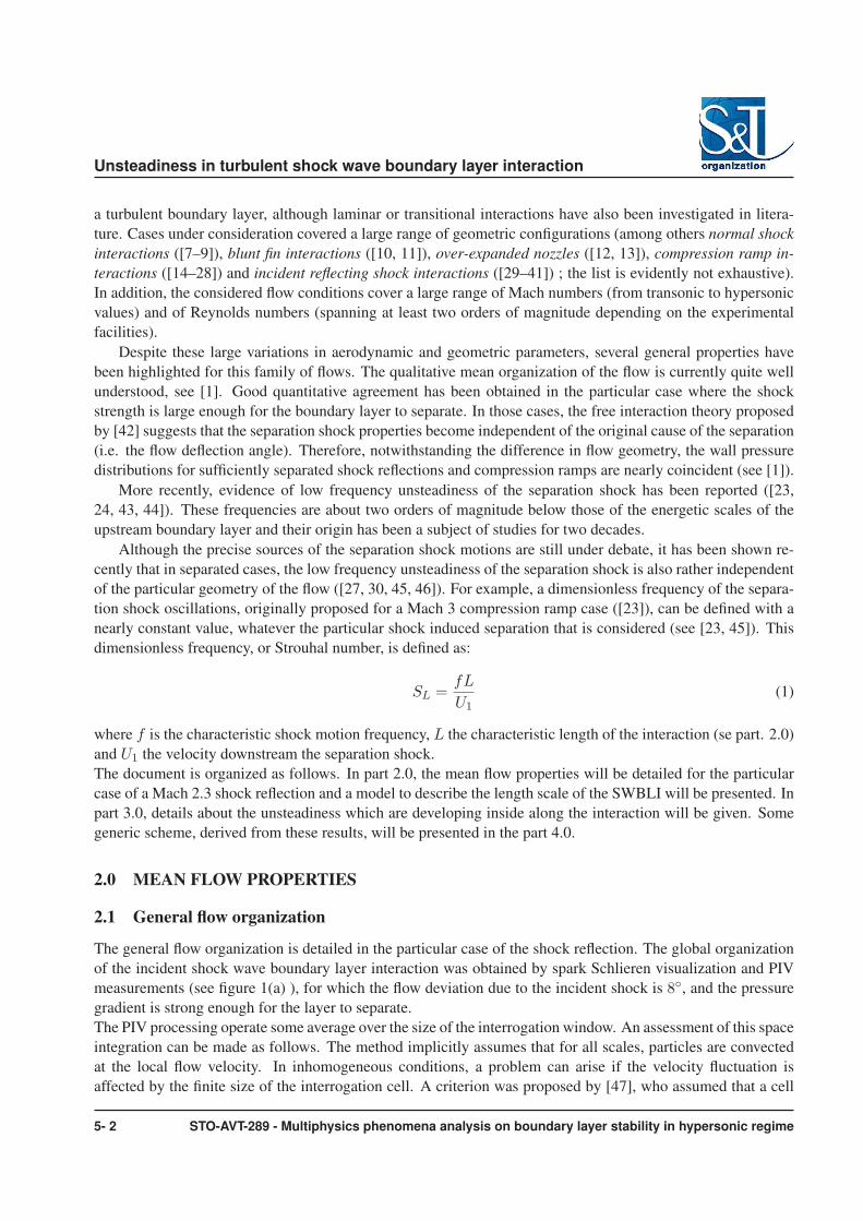
were determined in this frame of reference. The results for the velocity fields in the mixing layer coordinate

system are shown in figure 4, where X is now taken along the centerline and Y in the perpendicular direction.

It turns out that, within the range of accuracy all these quantities behave in a self-similar fashion, and have

shapes typical of mixing layers. Very similar results were obtained for a Mach 3 compression corner [51].

These results suggest that the separated shear layer may exhibit similar properties than canonical plane mixing

layer: such considerations were used to derive simple model to describe the unsteadiness which are developing

along the interaction (see part 3.0).

5- 6 STO-AVT-289 - Multiphysics phenomena analysis on boundary layer stability in hypersonic regime

Unsteadiness in turbulent shock wave boundary layer interaction

(a) (b)

Figure 4: Velocity profiles in the mixing layer coordinate system, θ = 9.5◦: (a): variance of the longitudinal velocity; (b): crosscorrelation normalized by U2

e .

2.4 Relaxation region

Considering Figure 1(a), high level of turbulence are observed downstream from the reattachment region. Just

downstream from the reattachment, the maxima of fluctuations are found far from the wall with similar level

as in the separated shear layer. The relaxation of the downstream boundary layer extends over more than 10

boundary layer thickness. Nevertheless, in the near wall region, where the relaxation process is faster, new

log-region can be observed scaling on the downstream wall properties. These high level of fluctuations will be

related to the unsteadiness which are developing along the separated shear layer (see part. 3.0).

3.0 UNSTEADINESS IN THE TSWBLI

In this section, unsteady properties will be considered. Since pioneer experiments in turbulent separated SWBLI

([18, 43, 52, 53]) among others, very low frequency shock motions have been observed, whatever the particular

geometry. The characteristic frequencies are about two order of magnitude lower than the energetic upstream

scales of the incoming turbulent boundary layer. More recently, DNS and LES simulations confirmed these

experimental results ([27, 46, 54, 55]). In the next sections the particular case of a shock reflection will be

presented, similar results were observed in other geometric configurations.

3.1 Shock waves unsteadiness

Experimental and numerical results show that when the shock intensity is strong enough to make the boundary

layer separate, the foot of the shock becomes unsteady and oscillates more or less randomly at very low fre-

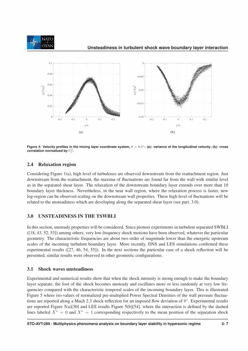
quencies compared with the characteristic temporal scales of the incoming boundary layer. This is illustrated

Figure 5 where iso-values of normalized pre-multiplied Power Spectral Densities of the wall pressure fluctua-

tions are reported along a Mach 2.3 shock reflection for an imposed flow deviation of 8◦. Experimental results

are reported Figure 5(a)[30] and LES results Figure 5(b)[54], where the interaction is defined by the dashed

lines labeled X∗ = 0 and X∗ = 1 corresponding respectively to the mean position of the separation shock

STO-AVT-289 - Multiphysics phenomena analysis on boundary layer stability in hypersonic regime 5- 7

Unsteadiness in turbulent shock wave boundary layer interaction

f(Hz)

X*

θ=8.0 fE(f)

101

102

103

104

−0.5

0

0.5

1

1.5

0.05

0.1

0.15

0.2

0.25

0.3

0.35

0.4

0.45

0.5

(a) (b)

Figure 5: Pressure power spectral density along the interaction (θ = 8◦). (a) experiments and (b) LES.

(a) (b)

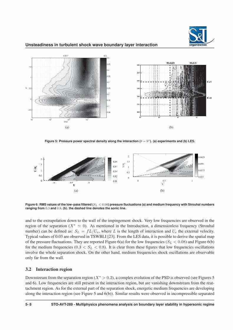
Figure 6: RMS values of the low–pass filtered (SL < 0.08) pressure fluctuations (a) and medium frequency with Strouhal numbersranging from 0.3 and 0.8. (b). the dashed line denotes the sonic line.

and to the extrapolation down to the wall of the impingement shock. Very low frequencies are observed in the

region of the separation (X∗� 0). As mentioned in the Introduction, a dimensionless frequency (Strouhal

number) can be defined as: SL = fL/Ue, where L is the length of interaction and Ue the external velocity.

Typical values of 0.03 are observed in TSWBLI [23]. From the LES data, it is possible to derive the spatial map

of the pressure fluctuations. They are reported Figure 6(a) for the low frequencies (SL < 0.08) and Figure 6(b)

for the medium frequencies (0.3 < SL < 0.8). It is clear from these figures that low frequencies oscillations

involve the whole separation shock. On the other hand, medium frequencies shock oscillations are observable

only far from the wall.

3.2 Interaction region

Downstream from the separation region (X∗ > 0.2), a complex evolution of the PSD is observed (see Figures 5

and 6). Low frequencies are still present in the interaction region, but are vanishing downstream from the reat-

tachment region. As for the external part of the separation shock, energetic medium frequencies are developing

along the interaction region (see Figure 5 and 6(b)). Similar results were observed in incompressible separated

5- 8 STO-AVT-289 - Multiphysics phenomena analysis on boundary layer stability in hypersonic regime

Unsteadiness in turbulent shock wave boundary layer interaction

0 0.5 1 1.50

0.25

0.5

X*

Z/L

0

1.26

2.52

Z/δ

0

(a) class 2

0 0.5 1 1.50

0.25

0.5

X*

Z/L

0

1.26

2.52

Z/δ

0

(b) class 6

0 0.5 1 1.50

0.25

0.5

X*

Z/L

0

1.26

2.52

Z/δ

0(c) class 9

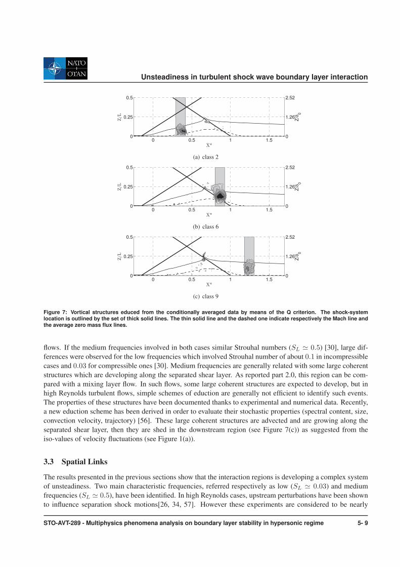
Figure 7: Vortical structures educed from the conditionally averaged data by means of the Q criterion. The shock-systemlocation is outlined by the set of thick solid lines. The thin solid line and the dashed one indicate respectively the Mach line andthe average zero mass flux lines.

flows. If the medium frequencies involved in both cases similar Strouhal numbers (SL � 0.5) [30], large dif-

ferences were observed for the low frequencies which involved Strouhal number of about 0.1 in incompressible

cases and 0.03 for compressible ones [30]. Medium frequencies are generally related with some large coherent

structures which are developing along the separated shear layer. As reported part 2.0, this region can be com-

pared with a mixing layer flow. In such flows, some large coherent structures are expected to develop, but in

high Reynolds turbulent flows, simple schemes of eduction are generally not efficient to identify such events.

The properties of these structures have been documented thanks to experimental and numerical data. Recently,

a new eduction scheme has been derived in order to evaluate their stochastic properties (spectral content, size,

convection velocity, trajectory) [56]. These large coherent structures are advected and are growing along the

separated shear layer, then they are shed in the downstream region (see Figure 7(c)) as suggested from the

iso-values of velocity fluctuations (see Figure 1(a)).

3.3 Spatial Links

The results presented in the previous sections show that the interaction regions is developing a complex system

of unsteadiness. Two main characteristic frequencies, referred respectively as low (SL � 0.03) and medium

frequencies (SL � 0.5), have been identified. In high Reynolds cases, upstream perturbations have been shown

to influence separation shock motions[26, 34, 57]. However these experiments are considered to be nearly

STO-AVT-289 - Multiphysics phenomena analysis on boundary layer stability in hypersonic regime 5- 9

Unsteadiness in turbulent shock wave boundary layer interaction

attached/incipient–separation configurations for which no reverse flow could be observed from Particle Image

Velocimetry (PIV) measurements in a time–average sense. In the separated cases, it is clear that the low fre-

quency separation shock motion are strongly correlated with the low freqency breathing of the separated region

(see [33]).

It has also been known for decades from unsteady wall-pressure measurements that specific phase relationships

are observed [23, 24, 30, 58]. For example, whatever the geometry (compression corner or shock reflection) and

Mach number (1.5 < M < 5), strong correlation at low frequency occurs between wall pressure fluctuations

created by the shock unsteadiness and those downstream from the shock. The initial region of the interaction ex-

hibits in–phase pressure fluctuations, while the region near the reattachment point presents anti–phase pressure

signals. These two regions are separated by a zone of null correlation whose origin is not yet well established.

Finally, as shown Figure 6(b), the separation shock motions are also involving medium frequencies, at least far

from the wall.

4.0 GENERIC SCHEMES FOR SEPARATED TSWBLI

Efforts have been put for many years to characterize the low frequency unsteadiness and several models derived

from experimental data and numerical simulations were introduced in order to define their sources, see Morgan

et al.[59].

In [33] a scenario of entrainment-discharge mechanism has been proposed, according to which the mixing

layer at the edge of the dead-air zone entrains air from the separated bubble, and sheds it into the downstream

layer. This produces a mass deficit in the recirculation, which, from time to time has to be re-fed by fresh air

flowing backwards. This mechanism defines a characteristic time (or frequency), which was used to evaluate the

frequency scale of the phenomenon, by assuming that the mass entrainment rate by the shear layer follows the

same laws as a canonical mixing layer, in particular for the Mach number dependence. A normalized Strouhal

number was defined:

Sl =fl

U1

= Φ(Mc)g(r, s)l

h(9)

where Φ(Mc) is the normalized speading rate of the compressible mixing layers, g(r, s) a parametric function

of the velocity (r) and density (s) ratios across the separated shear layer and l/h the aspect-ratio of the sep-

aration bubble. As the mixing process is related to the dynamics of the large coherent structures developing

along the separated shear layer, this relation suggest a direct influence of the geometry of the flow (its aspect

ratio) and an indirect influence between the medium frequencies and the low frequency breathing of the sep-

aration bubble. The model was able to give some relevant scaling for low-frequency shock unsteadiness in

various SWBLI configurations (see figure 8), but detailed descriptions of the process were not addressed. Other

works propose to consider the whole interaction as a dynamic system with its own transfer function. Initially

suggested in [52], this approach has been recently re-considered in the case of a Mach 2.3 shock reflection in

[61], where the interaction is proposed to act as a low pass filter for the upstream perturbations. This analysis,

based on the similitude properties of the flow inside the first part of the interaction, estimated with success the

characteristic time scale of shock unsteadiness in the IUSTI (Institut Universitaire des Systemes Thermiques

Industriels) 8◦ interaction. These two models differ mainly on the nature of the low frequency unsteadiness:

Touber & Sandham’s model suggests a broad band mechanism without a particular time scale, limited by the

equivalent cut-off frequency of the system. On the contrary, the model of Piponniau et al suggests the exis-

tence of a characteristic frequency, eventually with some time fluctuations, due to the turbulence and/or some

harmonics in the entrainment time scales. Both types of unsteadiness could even cohabit, as suggested in [61].

Several attempt has been carried out in order to identify intrinsic low frequency unsteady modes in the separated

5- 10 STO-AVT-289 - Multiphysics phenomena analysis on boundary layer stability in hypersonic regime

Unsteadiness in turbulent shock wave boundary layer interaction

0 0.5 1 1.5 2 2.5 3 3.5 4 4.5 50

1

2

3

4

5

6

7

8

9

10

M

SL.[

Φ(M

c).g

(r,s

)]−1

Figure 8: Dimensionless frequency of the shock oscillation normalized as suggested by relation 9: (�) subsonic separation from[60], other symbols are TSWBLI

region. In incompressible cases, global stability analysis suggest the development of discrete unsteady convec-

tive modes [62]. The authors suggest a non-linear mechanism between these convective modes to explain the

low frequency breathing of the separation bubble: nevertheless, no precise mechanism was provided. Similar

analysis was generalized for similar transonic[63–65] and supersonic cases[66]. It has been found from the

global stability analyses performed on compressible flow configurations without shock (M < 0.75) that these

flows behave similarly to the incompressible separated flows. For the transonic cases, two different behaviors

have been observed depending on the geometrical configuration. For the case of the flow around an airfoil with

a positive angle of attack, it was confirmed that the low-frequency buffet was related to a global instability

mode. For the other cases, namely a Me < 0.85 flow over a bump and the M = 2 shock reflection, a major

conclusion from the global stability analysis is that the base flowfield is stable, regardless of the configuration.

The low frequency unsteadiness are not modal in nature whatever the level of compressibility considered while.

The flow responses to optimal perturbations have consequently been studied, highlighting that both the transonic

and supersonic flows under consideration may act as selective noise amplifiers. Optimal perturbation analyses

have demonstrated that the flow acts as selective noise amplifiers, with a high sensitivity to disturbances in the

same medium frequency range that the one associated with unstable modes found for cases without shocks.

Consequently it seems that, regardless of the compressibility level, the low frequency unsteadiness are not

modal in nature and have to be related to: either a nonlinear mechanism involving unstable (or transiently

amplified) convective modes of higher frequencies, or a selective amplification of external low-frequency per-

turbations.

If the precise origin of these low frequencies is still under debate, some experimental results obtained in various

SWBLIs are not yet clearly explained by these different models. For example, the characteristic phase rela-

tionships and coherency (as recalled in part 3.3). From LES simulation, the details of the physical mechanism

have been explored, giving rise to the upstream and downstream influence on the shock motion [54, 55]; it also

identifies spatially the zones controlling the motion of the different part of the shock system, along with the

STO-AVT-289 - Multiphysics phenomena analysis on boundary layer stability in hypersonic regime 5- 11

Unsteadiness in turbulent shock wave boundary layer interaction

Φ

Φ ΠP

1S

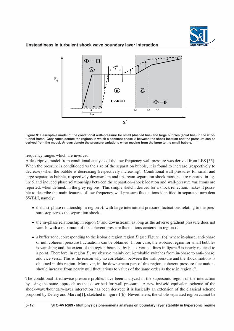
Figure 9: Descriptive model of the conditional wall–pressure for small (dashed line) and large bubbles (solid line) in the wind-tunnel frame. Grey zones denote the regions in which a constant phase Φ between the shock location and the pressure can bederived from the model. Arrows denote the pressure variations when moving from the large to the small bubble.

frequency ranges which are involved.

A descriptive model from conditional analysis of the low frequency wall pressure was derived from LES [55].

When the pressure is conditioned vs the size of the separation bubble, it is found to increase (respectively to

decrease) when the bubble is decreasing (respectively increasing). Conditional wall pressures for small and

large separation bubble, respectively downstream and upstream separation shock motions, are reported in fig-

ure 9 and induced phase relationships between the separation–shock location and wall-pressure variations are

reported, when defined, in the grey regions. This simple sketch, derived for a shock reflection, makes it possi-

ble to describe the main features of low frequency wall-pressure fluctuations identified in separated turbulent

SWBLI, namely:

• the anti–phase relationship in region A, with large intermittent pressure fluctuations relating to the pres-

sure step across the separation shock.

• the in–phase relationship in region C and downstream, as long as the adverse gradient pressure does not

vanish, with a maximum of the coherent pressure fluctuations centered in region C.

• a buffer zone, corresponding to the isobaric region region B (see Figure 1(b)) where in-phase, anti-phase

or null coherent pressure fluctuations can be obtained. In our case, the isobaric region for small bubbles

is vanishing and the extent of the region bounded by black vertical lines in figure 9 is nearly reduced to

a point. Therefore, in region B, we observe mainly equi-probable switches from in-phase to anti–phase,

and vice versa. This is the reason why no correlation between the wall pressure and the shock motions is

obtained in this region. Moreover, in the downstream part of this region, coherent pressure fluctuations

should increase from nearly null fluctuations to values of the same order as those in region C.

The conditional streamwise pressure profiles have been analyzed in the supersonic region of the interaction

by using the same approach as that described for wall pressure. A new inviscid equivalent scheme of the

shock-wave/boundary-layer interaction has been derived: it is basically an extension of the classical scheme

proposed by Delery and Marvin[1], sketched in figure 1(b). Nevertheless, the whole separated region cannot be

5- 12 STO-AVT-289 - Multiphysics phenomena analysis on boundary layer stability in hypersonic regime

Unsteadiness in turbulent shock wave boundary layer interaction

associated with an isobaric region since only region B exhibits a pressure gradient close to zero. In the second

part of the separated region (subregion C), a significant adverse pressure gradient develops and is associated

with large unsteady pressures. Moreover, it has been found from LES data analysis[55] that the shock system

balances the pressure between the subsonic and supersonic regions by means of reflected compression waves

produced by the reflection of the incident shock through the boundary layer[67]. Such compression waves,

seen in figure 1(a) as dark lines located upstream from the expansion fan, are inconsistent with the single ramp

scenario described in figure 1(b).

A new conceptual model, sketched in figure 10, is introduced to alleviate these shortcomings. A new second

ramp is added just upstream from the impingement point of the incident-shock. It splits the equivalent subsonic

region into two parts which can be associated respectively with regions B and C of the scheme introduced in

figure 9. The first ramp results in a flow deflection compatible with the free interaction theory, i.e. independent

of the size of the separation. The flow then undergoes a second deviation, due to the second ramp, and imposes

an increase in pressure. In the inviscid supersonic region, this leads to the creation of the shock C ′

3which

intersects the separation shock C4 near Hw, thus strengthening the separation shock up to the value C ′

4.

The low-frequency unsteadiness of the first ramp can be associated with the bubble breathing, which is linked

to the extent of region B with a small or null pressure gradient (isobaric region in cases of large separated

bubbles). This is the origin of the longitudinal displacements of the separation shock. On the other hand, the

second ramp unsteadiness involves a specific region of the interaction, typically 0.6 < X∗ < 0.9, see figure 9.

This corresponds to region C, where large pressure gradients are observed, downstream from the nearly iso-

baric region, as in subsonic separated cases. This pressure gradient ensures the connection with downstream

pressure in the separated region and generates weak pressure fluctuations at low frequency.

The influence of medium-frequency coherent structures on the reflection of incident shock have been shown

figure 6(b). Average values induced by the convection of coherent structures along the mixing layer are found

in region B while the foot of the incident shock/reflected compression waves experiences much higher values.

Large values are also recovered along the path of compression waves up to the location Hw at which they inter-

cept the separation shock, in agreement with the characteristics–based analysis of the propagation of pressure

disturbances, as developed in Agostini et al.[54]. Therefore, the inviscid equivalent model sketched in figure 10

can be extended to the medium-frequency unsteadiness. It is achieved by linking the medium-frequency un-

steadiness to the second ramp in order to include the pressure variations due to the interaction of the convective

structures with the adverse pressure gradient of region C. Therefore, the second ramp, associated with region

C in the scheme of figure 9, displays oscillations at two different characteristic frequencies:

• low frequency with SL � 0.03, associated with the bubble breathing,

• a medium frequency with SL � 0.5, associated with the convective structures and the rapid decrease in

their time scale in this region.

It should be stressed that the scheme presented does not explain the origin of low-frequency unsteadiness and

their possible correlation with medium frequencies generated by the coherent convective structures developing

in the separated shear layer. Nonetheless, whatever the precise mechanism linking the two frequency ranges,

the proposed simple inviscid scheme will describe accurately the whole field of unsteady pressure within and

downstream from the interaction. In particular, the phase relationships, the coherence maps, the evolution of the

pressure standard deviation and the convective velocities obtained along the head shock for various separation

state are qualitatively reproduced.

STO-AVT-289 - Multiphysics phenomena analysis on boundary layer stability in hypersonic regime 5- 13

Unsteadinessinturbulentshockwaveboundarylayerinteraction

C2

C1

ϕ1

ϕ2

0

1

C3

C3’2

3

3’ ϕD

ϕD

4’

C4’

C4

Hw

χ

Expansionfan

(a)Largeseparatedregion

C1

ϕ1

0

4’’

1

C2

ϕ2

2

C3

ϕD

ϕD

C4’’

3’’C4

Hw

χ

Expansionfan

(b)Smallseparatedregion

Figure10:Inviscidequivalentscenariooftheshockwaveboundarylayerinteractiondependingontheinteractionlength.

ACKNOWLEDGMENTS

ThisworkwaspartlysupportedbytheAgenceNationaldelaRecherche(ANR)throughtheDECOMOSprojectfromtheBlancprogramandfromtheCNESthroughtheresearchprogramATACaswellasfromtheLabexMecaniqueEtComplexite.Theresearchteamwasgrantedaccesstohigh–performancecomputingresourcesofInstitutduDeveloppementetdesRessourcesenInformatiqueScientifique(IDRIS)underallocations2009-021877and2010-021877madebyGrandEquipementNationaldeCalculIntensif(GENCI).Thesesupportsaregratefullyacknowledged.

REFERENCES

[1]Delery,J.M.andMarvin,J.G.,“Shockwave-boundarylayerinteractions,”Tech.rep.,1986.

[2]Viswanath,P.R.,“Shock-wave-turbulent-boundary-layerinteractionanditscontrol:Asurveyofrecentdevelopments,”Sadhana,Vol.12,1988,pp.45–104.

[3]Dolling,D.S.,“Fiftyyearsofshock-wave/boundary-layerinteractionresearch:whatnext,”AIAAJournal,Vol.39,No.8,August2001,pp.1517–1531.

[4]Smits,A.J.andDussauge,J.P.,Turbulentshearlayersinsupersonicflow,AIPPress,2nded.,2006.

[5]Clemens,N.T.andNarayanaswamy,V.,“Shock/TurbulentBoundaryLayerInteractions:ReviewofRe-cent WorkonSourcesofUnsteadiness,”39thFluidDynamicsConferenceandExhibit,SanAntonio,Texas,USA,AIAA-2009-3710,22-25June2009.

[6]Delery,J.M.andDussauge,J.P.,“Somephysicalaspectsofshockwave/boundarylayerinteractions,”ShockWaves,Vol.19,No.6,December2009,pp.453–468.

[7]Atkin,C.J.andSquire,L.C.,“AstudyoftheinteractionofanormalshockwavewithaturbulentboundarylayeratMachnumbersbetween1.30and1.55.”EuropeanJ.Mechanics,Vol.11,No.1,1992,pp.93–118.

5-14 STO-AVT-289-Multiphysicsphenomenaanalysisonboundarylayerstabilityinhypersonicregime

Unsteadiness in turbulent shock wave boundary layer interaction

[8] Bruce, P. J. K. and Babinsky, H., “Unsteady shock wave dynamics,” Journal of Fluid Mechanics, Vol. 603,

2008, pp. 463–473.

[9] Bur, R., Benay, R., Galli, A., and Berthouze, P., “Experimental and numerical study of forced shock-wave

oscillations in a transonic channel,” Aerospace Science and Technology, Vol. 10, 2008, pp. 265–278.

[10] Brusniak, L. and Dolling, D. S., “Physics of unsteady blunt-fin-induced shock wave/turbulent boundary

layer interactions,” Journal of Fluid Mechanics, Vol. 273, 1994, pp. 375–409.

[11] Unalmis, O. H. and Dolling, D. S., “On the possible relationship between low frequency unsteadiness

of shock-induced separated flow and Goertler vortices,” 27th AIAA Fluid Dynamics Conference, New

Orleans, Louisiana, USA, AIAA-1996-2002, 17-20 June 1996.

[12] Frey, M. and Hagemann, G., “Status of flow separation prediction in rocket nozzles,” AIAA Paper, , No.

98-3619, 1998.

[13] Bourgoing, A. and Reijasse, P. H., “Experimental analysis of unsteady separated flows in a supersonic

planar nozzle,” Shock Waves, Vol. 14, No. 4, 2005, pp. 251–258.

[14] Thomke, G. J. and Roshko, A., “Incipient separation of a turbulent boundary layer at high Reynolds

number in two-dimensional supersonic flow over a compression corner,” Tech. Rep. DAC-59819, NASA

Ames Research Center, January 1969.

[15] Spaid, F. W. and Frishett, J. C., “Incipient separation of a supersonic, turbulent boundary layer, including

effect of heat transfer,” AIAA Journal, Vol. 10, No. 7, July 1972, pp. 915–922.

[16] Settles, G. S., Fitzpatrick, T. J., and Bogdonoff, S. M., “Detailed study of attached and separated compres-

sion corner flowfields in high Reynolds number supersonic flow,” AIAA Journal, Vol. 17, 1979, pp. 579–

585.

[17] Ardonceau, P. L., “The Structure of Turbulence in a Supersonic Shock-Wave/Boundary-Layer Interac-

tion,” AIAA Journal, Vol. 22, No. 9, 1984, pp. 1254–1262.

[18] Dolling, D. S. and Or, C. T., “Unsteadiness of the shock wave structure in attached and separated com-

pression ramp flows,” Experiments in Fluids, Vol. 3, 1985, pp. 24–32.

[19] Smits, A. J. and Muck, K. C., “Experimental study of three shock wave / turbulent boundary layer inter-

actions,” Journal of Fluid Mechanics, Vol. 182, 1987, pp. 291–314.

[20] Kuntz, D. W., Amatucci, V. A., and Addy, A. L., “Turbulent Boundary-Layer Properties Downstream of

the Shock-Wave / Boundary-Layer Interaction,” AIAA Journal, Vol. 25, No. 5, May 1987, pp. 668–675.

[21] Selig, M. S., Andreopoulos, J., Muck, K. C., Dussauge, J. P., and Smits, A. J., “Details of a shock -

separated turbulent boundary layer at a compression corner,” AIAA Journal, Vol. 27, No. 7, July 1989,

pp. 862–869.

[22] Erengil, M. E. and Dolling, D. S., “Correlation of Separation Shock Motion with Pressure Fluctuations in

the Incoming Boundary Layer,” AIAA Journal, Vol. 29, No. 11, November 1991, pp. 1868–1877.

[23] Erengil, M. E. and Dolling, D. S., “Unsteady wave structure near separation in a Mach 5 compression

ramp interaction,” AIAA Journal, Vol. 29, No. 5, May 1991, pp. 728–735.

STO-AVT-289 - Multiphysics phenomena analysis on boundary layer stability in hypersonic regime 5- 15

Unsteadiness in turbulent shock wave boundary layer interaction

[24] Thomas, F. O., Putman, C. M., and Chu, H. C., “On the mechanism of unsteady shock oscillation in shock

wave/turbulent boundary layer interaction,” Experiments in Fluids, Vol. 18, 1994, pp. 69–81.

[25] Beresh, S. J., Clemens, N. T., and S.Dolling, D., “Relationship between upstream turbulent boundary

layer velocity fluctuations and separation shock unsteadiness,” AIAA Journal, Vol. 40, No. 12, dec 2002,

pp. 2412–2422.

[26] Ganapathisubramani, B., Clemens, N. T., and Dolling, D. S., “Effects of upstream boundary layer on the

unsteadiness of shock–induced separation,” Journal of Fluid Mechanics, Vol. 585, 2007, pp. 369–394.

[27] Wu, M. and Martin, M. P., “Analysis of shock motion in shockwave and turbulent boundary layer in-

teraction using direct numerical simulation data,” Journal of Fluid Mechanics, Vol. 594, January 2008,

pp. 71–83.

[28] Ringuette, M., Wu, M., and Martin, M. P., “Low Reynolds Number effects in a Mach 3 Shock/Turbulent–

Boundary–Layer Interaction,” AIAA Journal, Vol. 46, No. 7, July 2008, pp. 1884–1887.

[29] Green, J., “Reflexion of an oblique shock wave by a turbulent boundary layer,” Journal of Fluid Mechan-

ics, Vol. 40, 1970, pp. 81–95.

[30] Dupont, P., Haddad, C., and Debieve, J. F., “Space and time organization in a shock induced boundary

layer,” Journal of Fluid Mechanics, Vol. 559, 2006, pp. 255–277.

[31] Pirozzoli, S. and Grasso, F., “Direct numerical simulation of impiging shock wave / turbulent boundary

layer interaction at M=2.25,” Physics of Fluid, Vol. 18, 2006.

[32] Touber, E. and Sandham, N. D., “Oblique shock impinging on a turbulent boundary layer: low-frequency

mechanisms,” 38th AIAA Fluid Dynamics Conference, Seattle, Washington, USA, 23-26 June 2008.

[33] Piponniau, S., Dussauge, J. P., Debieve, J. F., and Dupont, P., “A simple model for low-frequency un-

steadiness in shock-induced separation,” Journal of Fluid Mechanics, Vol. 629, 2009, pp. 87–108.

[34] Humble, R. A., Elsinga, G. E., Scarano, F., and Van Oudheusden, B. W., “Three-dimensional instan-

taneous structure of a shock wave/turbulent boundary layer interaction,” Journal of Fluid Mechanics,

Vol. 622, 2009, pp. 33–62.

[35] Souverein, L. J., Van Oudheusden, B. W., Scarano, F., and Dupont, P., “Application of a dual-plane particle

image velocimetry (dual-PIV) technique for the unsteadiness characterization of a shock wave turbulent

boundary layer interaction,” Measurement Science and Technology, Vol. 20, No. 7, July 2009, pp. 074003

(16pp).

[36] Garnier, E., “Stimulated Detached Eddy Simulation of three–dimensional shock / boundary layer interac-

tion,” Shock Waves, Vol. 19, No. 6, December 2009, pp. 479–486.

[37] Touber, E. and Sandham, N. D., “Comparison of three large–eddy simulations of shock–induced turbulent

separation bubbles,” Shock Waves, Vol. 19, No. 6, December 2009, pp. 469–478.

[38] Pirozzoli, S., Beer, A., Bernardini, M., and Grasso, F., “Computational analysis of impinging shock–

wave boundary layer interaction under conditions of incipient separation,” Shock Waves, Vol. 19, No. 6,

December 2009, pp. 487–497.

5- 16 STO-AVT-289 - Multiphysics phenomena analysis on boundary layer stability in hypersonic regime

Unsteadiness in turbulent shock wave boundary layer interaction

[39] Souverein, L. J., Dupont, P., Debieve, J. F., Dussauge, J. P., Van Oudheusden, B. W., and Scarano, F.,

“Effect of Interaction Strength on Shock Wave Boundary Layer Interaction: Unsteady Behavior,” AIAA

Journal, Vol. 48, No. 7, 2010, pp. 1480–1493.

[40] Souverein, L., On the scaling and unsteadiness of shock induced separation, Phd thesis, Delft University

of Technology and the Universite de Provence - Aix–Marseille I, March 2010.

[41] Priebe, S., Tu, J. H., Rowley, C. W., and Martın, M. P., “Low-frequency dynamics in a shock-induced

separated flow,” Journal of Fluid Mechanics, Vol. 807, 2016, pp. 441–477.

[42] Chapman, D. R., Kuehn, D. M., and Larson, H. K., “Investigation of separated flow in supersonic and

subsonic streams with emphasis of the effect of transition,” Tech. rep., 1957.

[43] Dolling, D. S. and Murphy, M. T., “Unsteadiness of the separation shock wave structure in a supersonic

compression ramp flowfield,” AIAA Journal, Vol. 21, No. 12, dec 1983, pp. 1628–1634.

[44] Dolling, D. S. and Brusniak, L., “Separation shock motion in fin, cylinder, and compression ramp-induced

turbulent interactions,” AIAA Journal, Vol. 27, No. 6, jun 1989, pp. 734–742.

[45] Dussauge, J. P., Dupont, P., and Debieve, J. F., “Unsteadiness in shock wave boundary layer interactions

with separation,” Aerospace Science and Technology, Vol. 10, 2006, pp. 85–91.

[46] Touber, E. and Sandham, N. D., “Large–eddy simulation of low–frequency unsteadiness in a turbulent

shock–induced separation bubble,” Theoretical and Computational Fluid Dynamics, Vol. 23, No. 2, 2009,

pp. 79–107.

[47] J.P., D. and P, D., “On critical aerodynamic phenomena in compressible turbulent flows and their mea-

surement: an issue for PIVand optical methods,” Keynote Lectures, Pivnet II, Delft 6-8 juin, 2005.

[48] Souverein, L., Bakker, P., and Dupont, P., “A scaling analysis for turbulent shock wave boundary layer

interactions,” Journal of Fluid Mechanics, Vol. 714, 2013, pp. 505–535.

[49] Forliti, D., Tang, B., and Strykowski, P., “An experimental investigation of planar countercurrent turbulent

shear layers,” J. Fluid Mech., Vol. 530, 2005, pp. 241–264.

[50] Strykowski, P. J., Krothapalli, A., and Jendoubi, S., “The effect of counterflow on the development of

compressible shear layers,” Journal of Fluid Mechanics, Vol. 308, 1996, pp. 63–96.

[51] Helm, C., Martin, M., and Dupont, P., “Characterization of the shear layer in a Mach 3 shock / turbulent

boundary layer interaction,” Journal of Physics: Conference Series, Vol. 506, 2014.

[52] Plotkin, K., “Shock wave oscillation driven by turbulent boundary layer fluctuations,” AIAA Journal,

Vol. 13, No. 8, 1975, pp. 1036–1040.

[53] Andreopoulos, J. and Muck, K. C., “Some new aspects of the shock wave - boundary layer interaction in

compression ramp flows,” Journal of Fluid Mechanics, Vol. 180, 1987, pp. 405–428.

[54] Agostini, L., Larcheveque, L., Dupont, P., Debieve, J., and Dussauge, J., “Zones of influence and shock

motion in a shock boundary layer interaction,” AIAA Journal, Vol. 50, No. -6, june 2012, pp. 1377–1387.

STO-AVT-289 - Multiphysics phenomena analysis on boundary layer stability in hypersonic regime 5- 17

Unsteadiness in turbulent shock wave boundary layer interaction

[55] Agostini, L., Larcheveque, L., and Dupont, P., “Mechanism of shock unsteadiness in separated

shock/boundary-layer interactions,” Physics of Fluids, Vol. 27, No. 12, 2015, pp. 126103.

[56] Jiang, T., Larcheveque, L., and Dupont, P., “Eduction scheme for convective structures in turbulent com-

pressible separated flow,” 8th International Symposium On Turbulence and Shear Phenomena (TSFP8),

Poitiers ( FRANCE ), August 2013.

[57] Humble, R. A., Scarano, F., and Van Oudheusden, B. W., “Unsteady Effects in an Incident Shock

Wave/Turbulent Boundary Layer Interaction,” Journal of Fluid Mechanics, Vol. 635, 2009, pp. 47–74.

[58] Debieve, J. F. and Dupont, P., “Dependence between shock and separation bubble in a shock wave /

boundary layer interaction,” Schock Waves, Vol. 19, No. 6, 2009, pp. 499–506.

[59] Morgan, B., Duraisamy, K., Nguyen, N., Kawai, S., and Lele, S. K., “Flow physics and RANS mod-

elling of oblique shock/turbulent boundary layer interaction,” Journal of Fluid Mechanics, Vol. 729, 2013,

pp. 231–284.

[60] Kiya, M. and Sasaki, K., “Structure of a turbulent separation bubble,” Journal of Fluid Mechanics,

Vol. 137, 1983, pp. 83–113.

[61] Touber, E. and Sandham, N., “Low-order stochastic modelling of low-frequency motions in reflected

shock-wave/boundary-layer interactions,” Journal of Fluid Mechanics, Vol. 671, No. 3, 2011, pp. 417–

465.

[62] Ehrenstein, U. and Gallaire, F., “Two-dimensional global low-frequency oscillations in a separating

boundary-layer flow,” Journal of Fluid Mechanics, Vol. 614, 2008, pp. 315–327.

[63] Merle, M., Approches numeriques pour l’analyse de stabilite globale d’ecoulements parietaux en regime

subsonique, Ph.D. thesis, ENSAM, 2015.

[64] Merle, M., Ehrenstein, U., and Robinet, J.-C., “Global stability of compressible laminar flow over a

bump: an absorbing boundary conditions approach,” 10th EUROMECH Fluid Mechanics Conference,

Copenhagen, Denmark, September 14-18, 2014.

[65] Sartor, F., Mettot, C., Bur, R., and Sipp, D., “Unsteadiness in transonic shock-wave/boundary-layer inter-

actions: experimental investigation and global stability analysis,” Journal of Fluid Mechanics, Vol. 781,

10 2015, pp. 550–577.

[66] Guiho, F., Alizard, F., and Robinet, J.-C., “Instabilities in oblique shock wave/laminar boundary-layer

interactions,” Journal of Fluid Mechanics, Vol. 789, 2016, pp. 1–35.

[67] Henderson, L. F., “The reflexion of a shock wave at a rigid wall in the presence of a boundary layer,”

Journal of Fluid Mechanics, Vol. 30, No. 04, 1967, pp. 699.

5- 18 STO-AVT-289 - Multiphysics phenomena analysis on boundary layer stability in hypersonic regime


Recommended