23
Multiple-clock Domain FPGA Designs: Challenges & Solutions Reuven Dobkin, CTO SEFUW, ESTEC, 2018 SEFUW, ESTEC, 2018

Multiple-clock Domain FPGA Designs:
Challenges & Solutions
Reuven Dobkin, CTO
SEFUW, ESTEC, 2018
SEFUW, ESTEC, 2018

vSync Circuits
• EDA & IP Company
• Mission:• Develop and provide our customers with
Integration and Verification solutions
for Multiple Clock Domain Designs
SEFUW, ESTEC, 20182

Outline
• Multiple-Clock Domain (MCD) Designs • A few anecdotes
• Tips & Tricks
• 3 MCD Challenges
• A note on Vincent (on whom?)
SEFUW, ESTEC, 20183
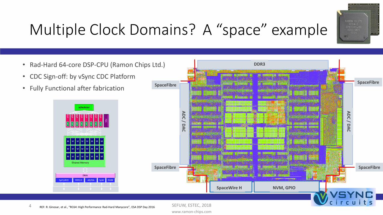
A “space” example
• Rad-Hard 64-core DSP-CPU (Ramon Chips Ltd.)
• CDC Sign-off: by vSync CDC Platform
• Fully Functional after fabrication
SEFUW, ESTEC, 20184www.ramon-chips.com
SpaceFibreSpaceFibre
SpaceFibreSpaceFibre
SpaceWire H NVM, GPIO
DDR3
AD
C / D
AC
AD
C / D
AC
REF: R. Ginosar, et al., “RC64: High Performance Rad-Hard Manycore”, ESA DSP Day 2016
Multiple Clock Domains?
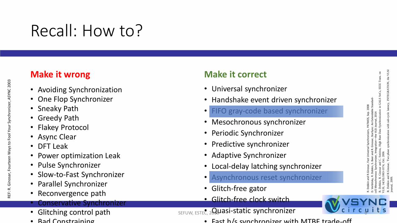
Recall: How to?
Make it wrong
• Avoiding Synchronization• One Flop Synchronizer• Sneaky Path• Greedy Path• Flakey Protocol• Async Clear• DFT Leak• Power optimization Leak• Pulse Synchronizer• Slow-to-Fast Synchronizer• Parallel Synchronizer• Reconvergence path• Conservative Synchronizer• Glitching control path• Bad Constraining
Make it correct
• Universal synchronizer
• Handshake event driven synchronizer
• FIFO gray-code based synchronizer
• Mesochronous synchronizer
• Periodic Synchronizer
• Predictive synchronizer
• Adaptive Synchronizer
• Local-delay latching synchronizer
• Asynchronous reset synchronizer
• Glitch-free gator
• Glitch-free clock switch
• Quasi-static synchronizer
• Fast h/s synchronizer with MTBF trade-offSEFUW, ESTEC, 2018 6
RE
F: R
. Gin
osa
r,Fo
urt
een
Way
s to
Fo
ol Y
ou
r Sy
nch
ron
izer
, ASY
NC
200
3
R. D
ob
kin
an
dR
.Gin
osa
r,Fa
st U
niv
ersa
l Sy
nch
ron
izer
s, P
ATM
OS,
Sep
. 2
00
8
D.V
erb
itsk
y, R
. Do
bki
n, S
. B
eer
and
R. G
ino
sar,
Star
Syn
c: A
n E
xten
dab
le S
tandar
d-
cell
Mes
och
ron
ou
sSy
nch
ron
izer
, In
tegr
atio
n—
the
VLS
I Jo
urn
al,
20
14
R.
Dobkin
, R
. G
inosa
r an
d C
. S
oti
riou,
Hig
h R
ate
Dat
a S
ynch
roniz
atio
n i
n G
AL
SS
oC
s, I
EE
E T
rans.
on
VL
SI,
14(1
0):
1063
-10
74,
Oct
. 2006
R.
Dobkin
and
R.G
inosa
r,T
wo p
has
e sy
nch
roniz
atio
n w
ith s
ub-c
ycl
e la
tency
, IN
TE
GR
AT
ION
, th
e V
LS
I
journ
al,
2009.

A few notes on FIFO design (1)
• Eliminate glitching into Sync: Gray Encoder output must be sampled
SEFUW, ESTEC, 20187
MEMORY
RAM or FFs
WR_PORT
WR_PNT
RD_PORT
RD_PNT
WR_PNT_SYNC
RD_PNTRD_PNT_SYNC
WR_PNT_CODED
N-Flop Sync
N-Flop Sync
Binary2GrayEnc
Binary2GrayDec
Binary2GrayEnc
Binary2GrayDec
WR_PNT
_NXT
Registered
output
Registered
output
RD_PNT_CODED

A few notes on FIFO design (2)
• RAM write could be “tricky”: Check out the RAM specification for write latency
SEFUW, ESTEC, 20188
MEMORY
RAM
WR_PORT
WR_PNT
RD_PORT
RD_PNT
WR_PNT_SYNC
RD_PNTRD_PNT_SYNC
WR_PNT_CODED
N-Flop Sync
N-Flop Sync
Binary2GrayEnc
Binary2GrayDec
Binary2GrayEnc
Binary2GrayDec
WR_PNT
_NXT
Registered
output
Registered
output
RD_PNT_CODED
WR_CLK
Additional register
(only for RAM-configuration)

A few notes on FIFO design (3)
• Register Read side data output + enable (who knows how it is used further…)
SEFUW, ESTEC, 20189
MEMORY
FFs
WR_CLK Domain
WR_PORT
WR_PNT
RD_PORT
RD_PNT
WR_PNT_SYNC
RD_PNTRD_PNT_SYNC
WR_PNT_CODED
N-Flop Sync
N-Flop Sync
Binary2GrayEnc
Binary2GrayDec
Binary2GrayEnc
Binary2GrayDec
WR_PNT
_NXT
Registered
output
Registered
output
RD_PNT_CODED
WR_CLK
Additional register
(only for RAM-configuration)
Control
NotEmptyLogic
EN
Registered
output
CDC!

Asynchronous Reset CDC
10
Fast clocks
CLK R SUT T T
F2
RST
D Q
CLK
CLK
ResetGenerator
/Synchronizer
RSTO
TR
Reset distribution network
Large designs
• Reset must meet setup/hold constrains
CLK
F0
RST
D Q
CLK
F1
RST
D Q
CLK
“1”
RSTI
RSTO_N(active low)
CLK
F0D Q
CLK
F1D Q
CLK
RSTIRSTO
Asynchronous Reset Synchronizers
REF: R. Dobkin, Asynchronous Reset Synchronization and Distribution, embedded.com, 2017
SEFUW, ESTEC, 2018
11
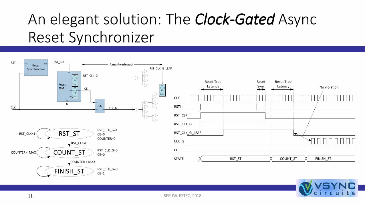
An elegant solution: The Clock-Gated AsyncReset Synchronizer
ICG
F3
RST
D Q
CLK
ResetFSM
CLK
RSTIReset
Synchhronizer
RSTI
CLK
RSTO
CLK
F2
RST
D Q
CLK
F1
SET
D Q
CLK
EN
CLKI CLKO
RST_CLK_GRST
CE
RST_CLK
CLK_G
RST_CLK_G_LEAF
A multi-cycle path
RST_CLK_G=1CE=0COUNTER=0
RST_CLK=1 RST_ST
RST_CLK_G=0CE=0
COUNTER < MAX COUNT_ST
RST_CLK=0
RST_CLK_G=0CE=1FINISH_ST
COUNTER = MAX
RSTI
CLK
RST_CLK
RST_CLK_G
RST_CLK_G_LEAF
Reset Tree Latency
CLK_G
Reset Sync
Reset Tree Latency
CE
RST_ST COUNT_STSTATE FINISH_ST
No violation
SEFUW, ESTEC, 2018
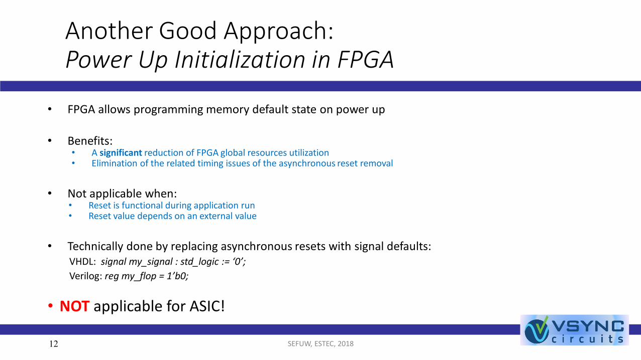
Another Good Approach:Power Up Initialization in FPGA
• FPGA allows programming memory default state on power up
• Benefits: • A significant reduction of FPGA global resources utilization• Elimination of the related timing issues of the asynchronous reset removal
• Not applicable when:• Reset is functional during application run• Reset value depends on an external value
• Technically done by replacing asynchronous resets with signal defaults:VHDL: signal my_signal : std_logic := ‘0’;
Verilog: reg my_flop = 1’b0;
• NOT applicable for ASIC!
12 SEFUW, ESTEC, 2018

Multiple Clock Design Challenges
• Setup: Clock & Reset requirements...
• Complexity: design and verification
• Integration: (Black-box) Third-party IPs
SEFUW, ESTEC, 201813

Getting Requirements…
SEFUW, ESTEC, 201814
G.I.G.O.
• Clocks setup – Who is Who?
• Clock relationships
• Clock sources
• Async, meso, periodic, etc.
• Intra Black-box clock manipulations
• Clock switching (e.g. SpaceWire)
• Reset setup – Who is Who?
• Reset sequences
• Power up / @ runhttp://safetyandcommonsense.blogspot.co.il/2010/10/garbage-ingarbage-out.html
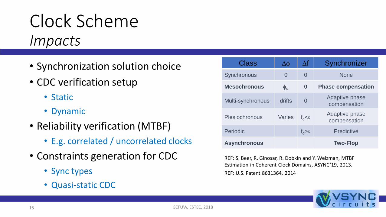
Clock SchemeImpacts
SEFUW, ESTEC, 201815
Class Df Df Synchronizer
Synchronous 0 0 None
Mesochronous fc 0 Phase compensation
Multi-synchronous drifts 0Adaptive phase
compensation
Plesiochronous Varies fd<eAdaptive phase
compensation
Periodic fd>e Predictive
Asynchronous Two-Flop
• Synchronization solution choice
• CDC verification setup
• Static
• Dynamic
• Reliability verification (MTBF)
• E.g. correlated / uncorrelated clocks
• Constraints generation for CDC
• Sync types
• Quasi-static CDC
REF: S. Beer, R. Ginosar, R. Dobkin and Y. Weizman, MTBF Estimation in Coherent Clock Domains, ASYNC’19, 2013.
REF: U.S. Patent 8631364, 2014

Clock & Reset RequirementsSolutions
Challenges
• Clocks setup – Who is Who?• Clock relationships
• Clock sources• Async, meso, periodic, etc.
• Intra Black-box clock manipulations
• Clock switching
• Reset setup – Who is Who?• Reset sequences
• Power up / @ run
Solutions (EDA)
• Auto Clock and Reset setup
• Clock & Reset trees auto recognition
• Vendor-IP recognition (e.g. PLLs)
• SDC
• Call for user intervention when needed
• Multi-modal analysis support
• Clock-gating / switching
SEFUW, ESTEC, 2018 16

Multiple Clock Design Challenges
• Setup: Clock & Reset requirements...
• Complexity: design and verification
• Integration: (Black-box) Third-party IPs
SEFUW, ESTEC, 201817
ComplexityKey issues
• Large designs • Long runtimes
• Many clocks • Multiple clock relations, large results set
• Many CDCs • A need to design multiple synchronizers
• Multiple Quasi-Static CDCs
• Many third-party IPs• False alarms, undiscovered CDC issues
• Many operation modes• Long runtimes, enormously large results set
18 SEFUW, ESTEC, 2018
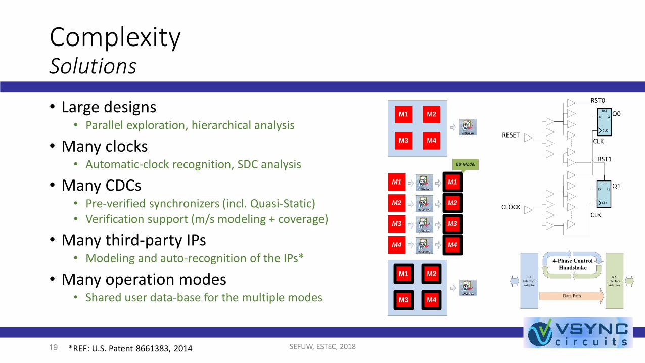
ComplexitySolutions
19 *REF: U.S. Patent 8661383, 2014
• Large designs • Parallel exploration, hierarchical analysis
• Many clocks • Automatic-clock recognition, SDC analysis
• Many CDCs • Pre-verified synchronizers (incl. Quasi-Static)• Verification support (m/s modeling + coverage)
• Many third-party IPs• Modeling and auto-recognition of the IPs*
• Many operation modes• Shared user data-base for the multiple modes
SEFUW, ESTEC, 2018
M1 M2
M3 M4
M1 M1
M2 M2
M3 M3
M4 M4
M1 M2
M3 M4
BB Model
RST
D Q
CLK
RESET
Q1RST
D Q
CLK
Q0
RST0
RST1
CLOCKCLK
CLK

Multiple Clock Design Challenges
• Setup: Clock & Reset requirements...
• Complexity: design and verification
• Integration: (Black-box) Third-party IPs
SEFUW, ESTEC, 201820

(Black-box) Third-party IPsKey issues
• Third-party IP modules• Open-source
• Encrypted
• May have internal synchronization schemes
• May have internal synchronization bugs…• May cause CDC bugs, when incorrectly connected
• Single / Multi-instance connections
21 SEFUW, ESTEC, 2018
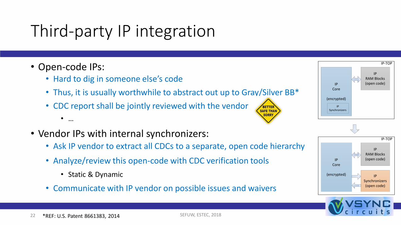
Third-party IP integration
SEFUW, ESTEC, 201822
• Open-code IPs:• Hard to dig in someone else’s code
• Thus, it is usually worthwhile to abstract out up to Gray/Silver BB*
• CDC report shall be jointly reviewed with the vendor
• …
• Vendor IPs with internal synchronizers:• Ask IP vendor to extract all CDCs to a separate, open code hierarchy
• Analyze/review this open-code with CDC verification tools
• Static & Dynamic
• Communicate with IP vendor on possible issues and waivers
IPCore
(encrypted)
IPRAM Blocks(open code)
IPSynchronizers(open code)
IP-TOP
IPCore
(encrypted)
IPRAM Blocks(open code)
IP-TOP
IPSynchronizers
*REF: U.S. Patent 8661383, 2014
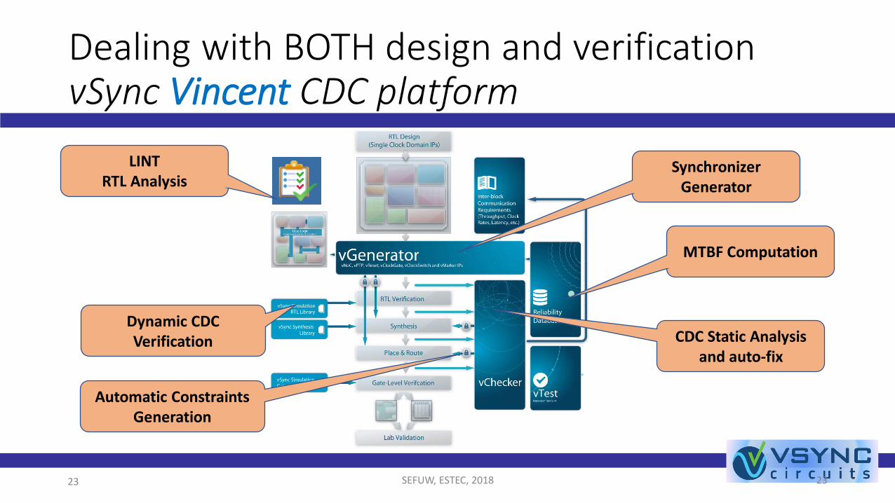
Dealing with BOTH design and verificationvSync Vincent CDC platform
SEFUW, ESTEC, 2018 2323
Synchronizer Generator
MTBF Computation
CDC Static Analysis and auto-fix
Automatic Constraints Generation
Dynamic CDC Verification
LINTRTL Analysis
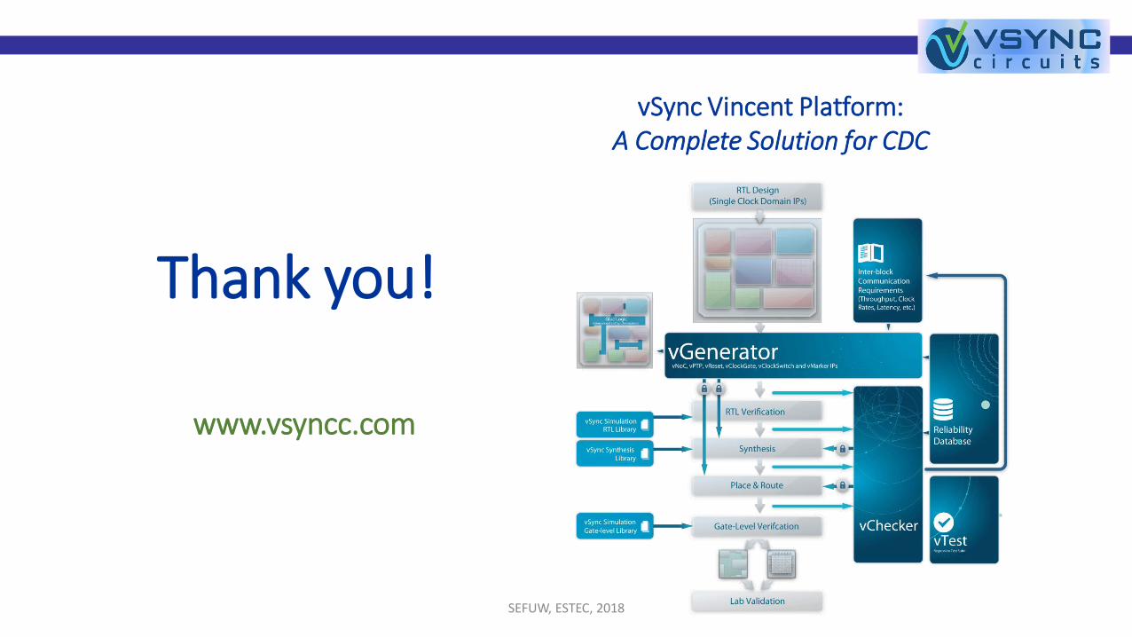
vSync Vincent Platform:A Complete Solution for CDC
Thank you!
www.vsyncc.com
SEFUW, ESTEC, 2018


