Multiple Environment Over Stress Testing (MEOST) A Primer with Examples from an Automotive Component Supplier October 26, 2011 John Kreucher Delphi Powertrain Auburn Hills, Michigan 810-577-9344 [email protected]
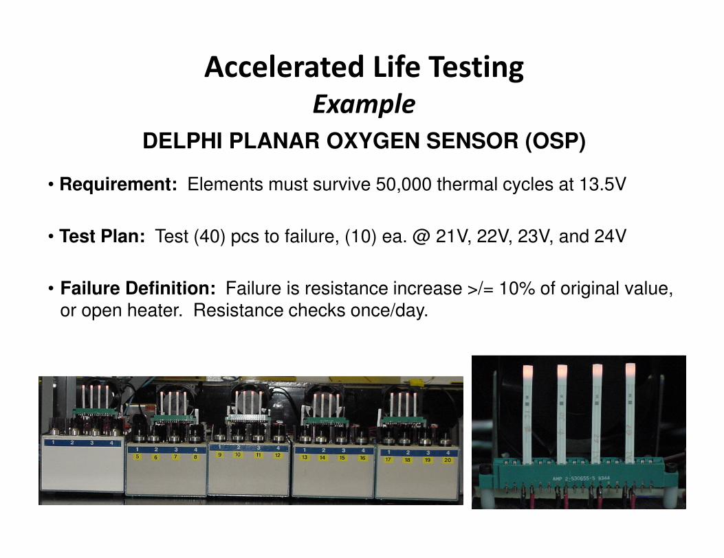
• Test Plan: Test (40) pcs to failure, (10) ea. @ 21V, 22V, 23V, and 24V
• Failure Definition: Failure is resistance increase >/= 10% of original value, or open heater. Resistance checks once/day.
• Requirement: Elements must survive 50,000 thermal cycles at 13.5V
Case Study 2:
Accelerated Heater Cycling Test
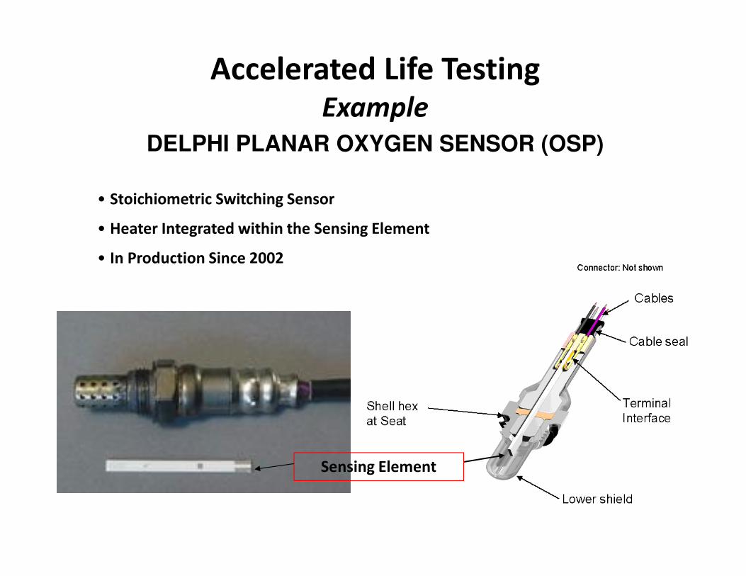
DELPHI PLANAR OXYGEN SENSOR (OSP)
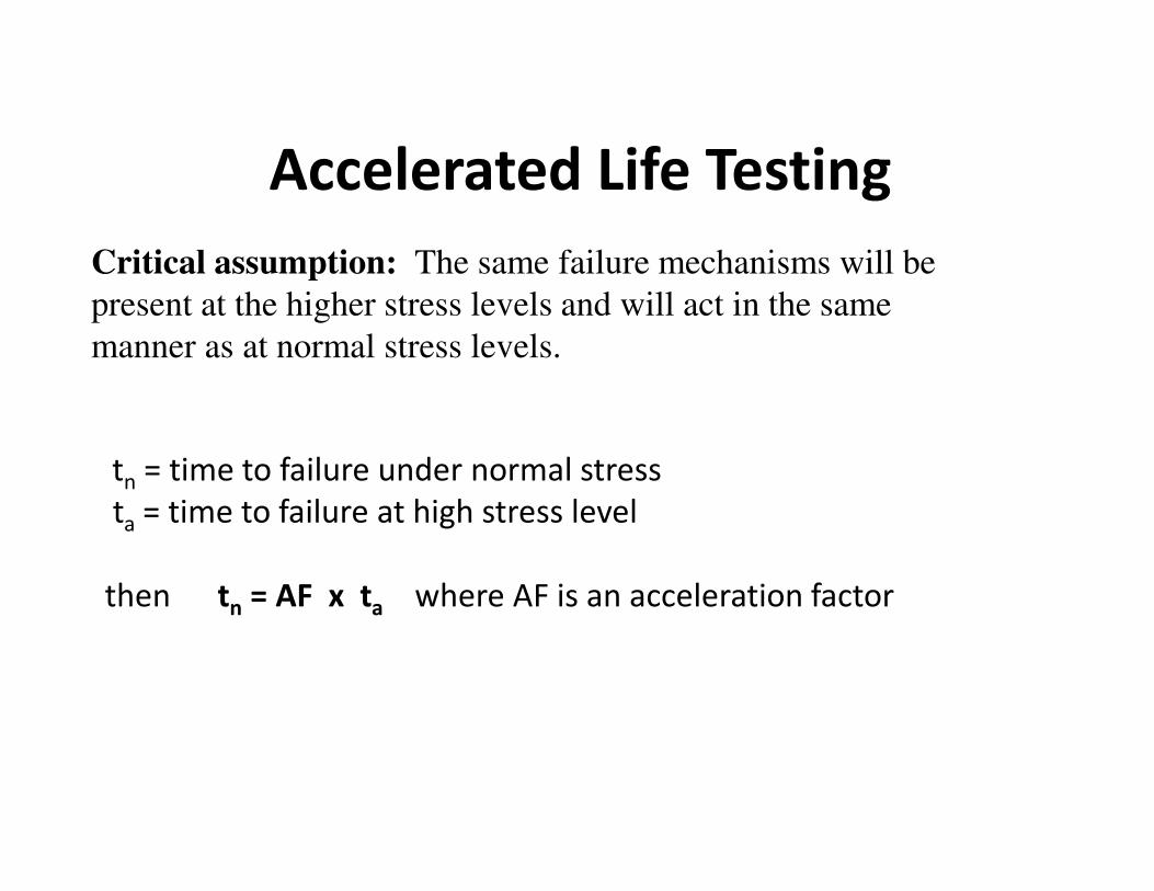
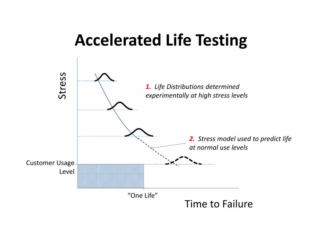
Accelerated Life Testing
Example
Case Study 2:
Accelerated Heater Cycling Test
DELPHI PLANAR OXYGEN SENSOR (OSP)
Accelerated Life Testing
Example
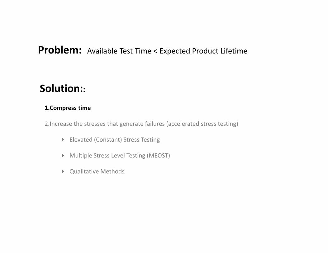
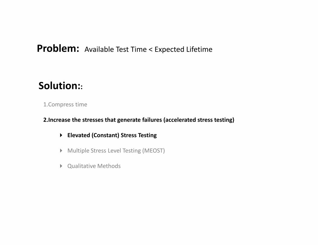
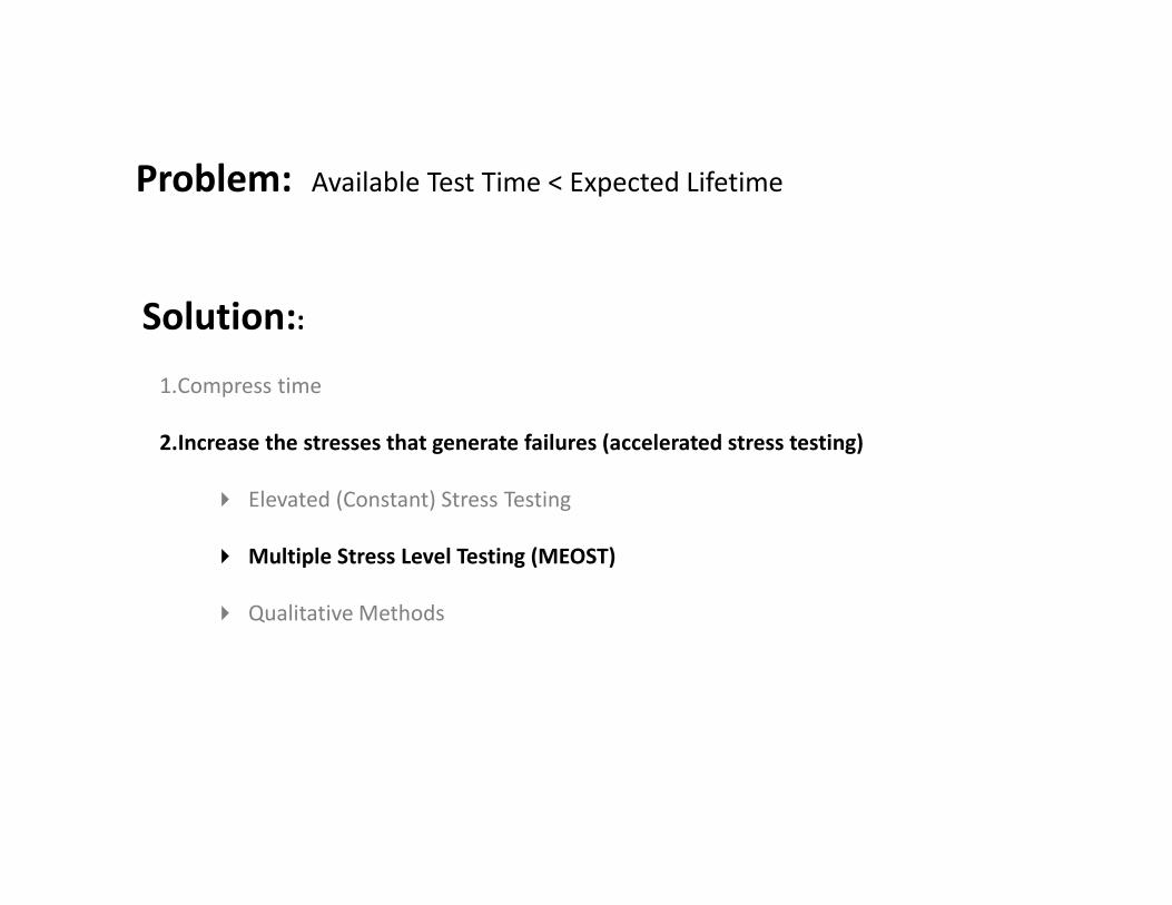
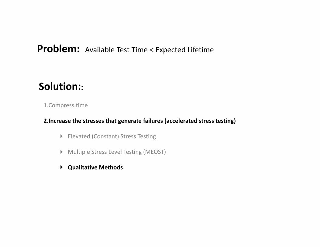
1.Compress time
2.Increase the stresses that generate failures (accelerated stress testing)
� Elevated (Constant) Stress Testing
� Multiple Stress Level Testing (MEOST)
� Qualitative Methods
Problem: Available Test Time < Expected Lifetime
Solution::
• Multiple environment test to failure after achieving one life
• All parts should fail on or before the last step of overstress (at the Destruct Limit)
• Combined environments allow for interactions which are potentially more
relevant than single environment tests
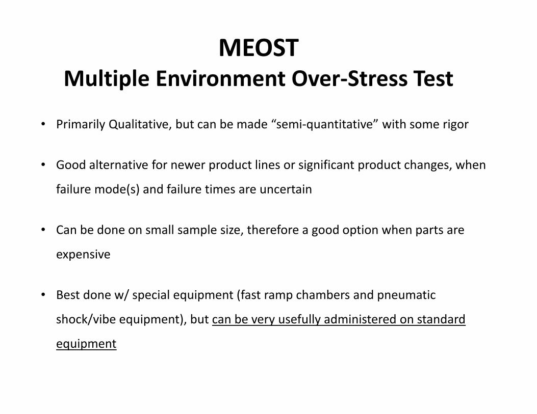
MEOST
Multiple Environment Over-Stress Test
MEOST
Multiple Environment Over-Stress Test
• Primarily Qualitative, but can be made “semi-quantitative” with some rigor
• Good alternative for newer product lines or significant product changes, when
failure mode(s) and failure times are uncertain
• Can be done on small sample size, therefore a good option when parts are
expensive
• Best done w/ special equipment (fast ramp chambers and pneumatic
shock/vibe equipment), but can be very usefully administered on standard
equipment
MEOST
Test Time
Co
mb
ine
d T
es
t S
tre
ss
100%
One Life
Destruct Limit
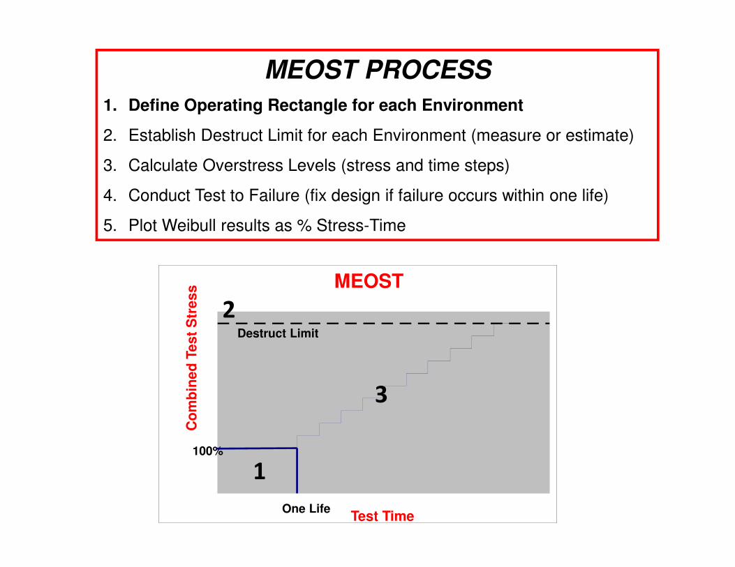
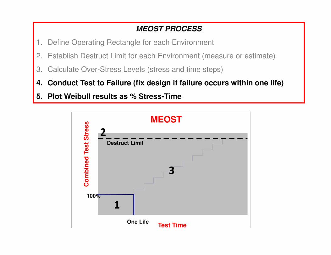
MEOST PROCESS
1. Define Operating Rectangle for each Environment
2. Establish Destruct Limit for each Environment (measure or estimate)
3. Calculate Overstress Levels (stress and time steps)
4. Conduct Test to Failure (fix design if failure occurs within one life)
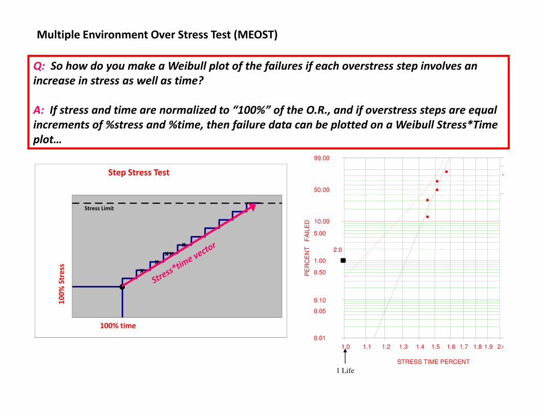
5. Plot Weibull results as % Stress-Time
1
2
3
MEOST
Operating Rectangle
1. Which environments are present? Which might interact to cause relevant failure modes? Conversely, too many environments lead to test complexity and cost.
2. Instrument your product in the field and record data for each important environment.
3. Analyze data to determine the (say) 97.5th %-tile user : The “Design Level”
4. Define the operating profile and one life on test.
Easy Level
MEOST
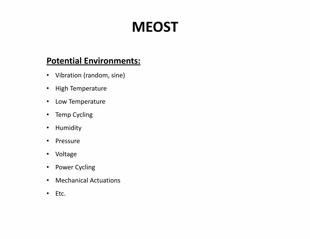
Potential Environments:
• Vibration (random, sine)
• High Temperature
• Low Temperature
• Temp Cycling
• Humidity
• Pressure
• Voltage
• Power Cycling
• Mechanical Actuations
• Etc.
MEOST
Conduct Test to One Life
1. Test 10 to 12 randomly selected units for one life within the operating rectangle.
• You should expect to pass!
2. Find and fix any failures, and restart the test.
• This might include design or quality improvements
3. Proceed to step stress testing with the same parts.
MEOST
Test Time
Co
mb
ine
d T
es
t S
tre
ss
100%
One Life
Destruct Limit
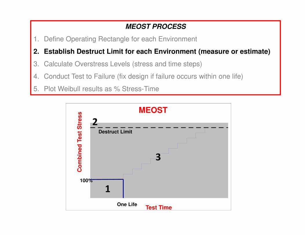
MEOST PROCESS
1. Define Operating Rectangle for each Environment
2. Establish Destruct Limit for each Environment (measure or estimate)
3. Calculate Overstress Levels (stress and time steps)
4. Conduct Test to Failure (fix design if failure occurs within one life)
5. Plot Weibull results as % Stress-Time
1
2
3
MEOSTDestruct Limit
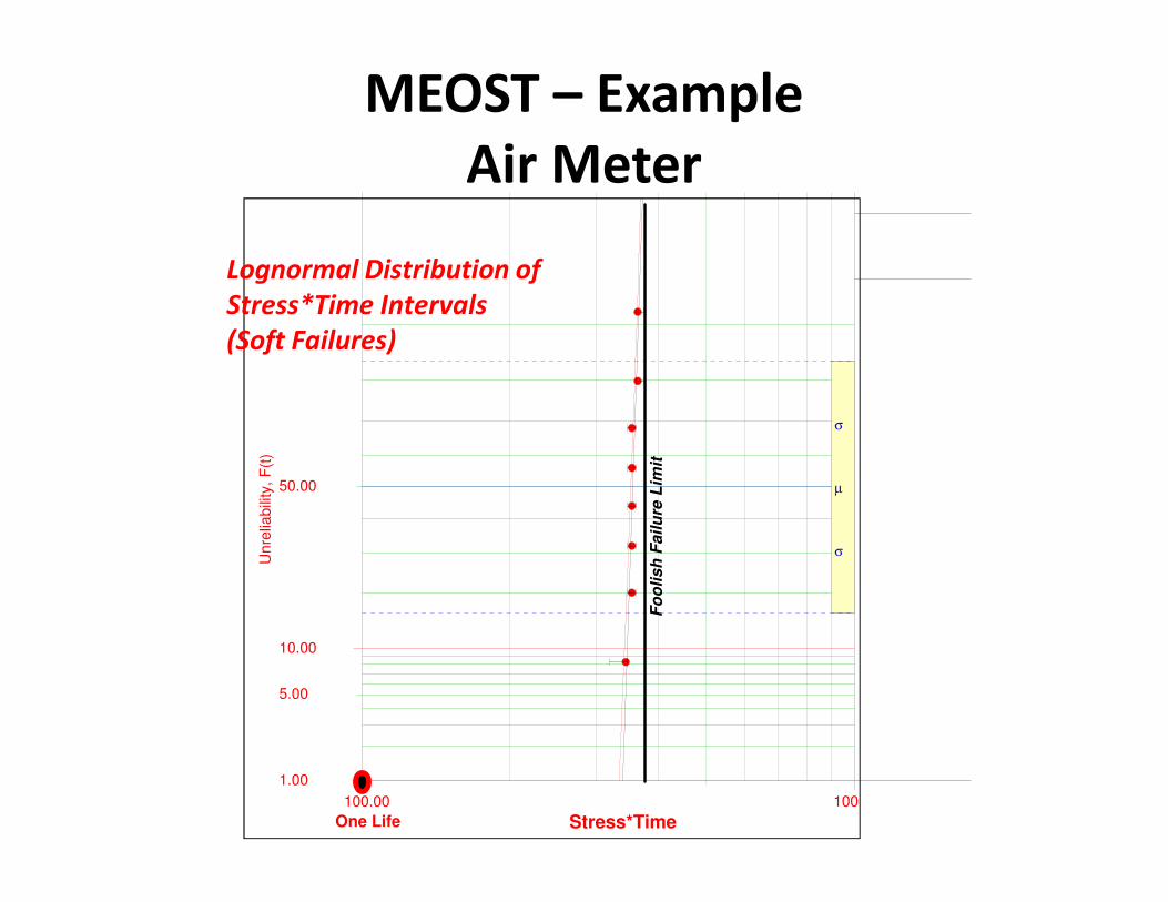
• The Destruct Limit (or Foolish Failure Limit) is the stress level where a product is
expected to fail with a high degree of certainty.
• The associated failure mode can be either related or unrelated to the failure
mode expected in the field environment.
• Example 1: Plastic case melting at 180 deg C.
• Example 2: PCB cracking at 10 Grms random vibration.
• Destruct Limits are best determined by testing parts under each environment
separately. Otherwise, analysis may be used (e.g. solder melt temp).
• Sometimes it is difficult or impossible to determine the Destruct Limit for a particular
environment due to test equipment limitations
• This may or may not compromise the integrity of the test plan
MEOST
Test Time
Co
mb
ine
d T
es
t S
tre
ss
100%
One Life
Destruct Limit
MEOST PROCESS
1. Define Operating Rectangle for each Environment
2. Establish Destruct Limit for each Environment (measure or estimate)
3. Calculate Over-Stress Levels (stress and time steps)
4. Conduct Test to Failure (fix design if failure occurs within one life)
5. Plot Weibull results as % Stress-Time
1
2
3
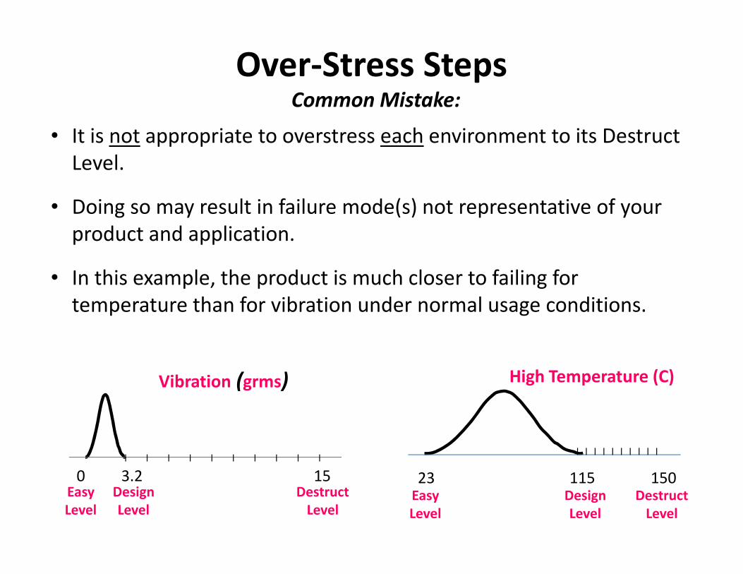
Over-Stress StepsCommon Mistake:
0 3.2 15 23 115 150
Vibration (grms) High Temperature (C)
Design
LevelDesign
Level
Destruct
LevelDestruct
Level
Easy
Level
Easy
Level
• It is not appropriate to overstress each environment to its Destruct
Level.
• Doing so may result in failure mode(s) not representative of your
product and application.
• In this example, the product is much closer to failing for
temperature than for vibration under normal usage conditions.
l l l l l l l l l ll l l l l l l l l l
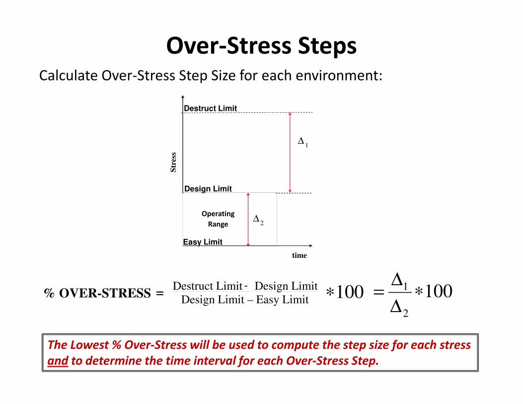
Over-Stress StepsCalculate Over-Stress Step Size for each environment:
1002
1 ∗∆
∆=% OVER-STRESS =
Destruct Limit - Design Limit
Design Limit – Easy Limit=
-
Operating
Range
∆1
∆2
Str
ess
Destruct Limit
time
Design Limit
Easy Limit
100∗
The Lowest % Over-Stress will be used to compute the step size for each stress
and to determine the time interval for each Over-Stress Step.
Over-Stress StepsExample: Electronic Component Test
Standard Validation Test:
• Temp Cycles between -40C and 115C
• Random vibration profile with energy of 3.2 grms
• One Life on this test is considered to be 400 Hrs
1. Operating Rectangle
• Stresses (Easy - Design Limit):
• High Temperature (23C - 115C)
• Vibrational Energy (0g - 3.2g)
• Low Temp: Held at -40C
• One Life = 400 Hrs
2. Destruct Limits:
• High Temp: 150C (softening temperature of plastic case)
• Vibration: 15grms (based on vibration test in worst-case orientation)
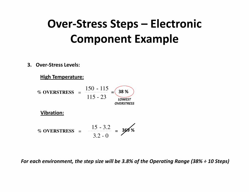
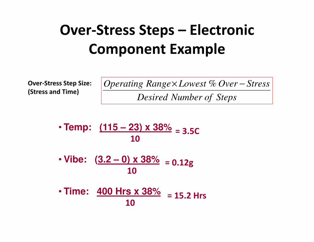
Over-Stress Steps – Electronic
Component Example
3. Over-Stress Levels:
High Temperature:
38 %
LOWEST OVERSTRESS
% OVERSTRESS =150 - 115
115 - 23
-=
Vibration:
369 %% OVERSTRESS =15 - 3.2
3.2 - 0
-=
For each environment, the step size will be 3.8% of the Operating Range (38% ÷ 10 Steps)