We request you to use the Learning material in the CD form
provided with this supply.
Your this act will help to save paper.
Please remember that each paper manual requires 50-100 sheets of paper
on an average.
Your CD learning material has
colourful diagrams,
plenty of theory,
detailed experiments with observation tables,
frequently asked questions, etc.
…….. and more so sometimes videos as well.
Scientech Eco Foundation
Scientech 4077
Scientech Technologies Pvt. Ltd. 3
Scientech 4077
Scientech Technologies Pvt. Ltd. 4
RoHS Compliance
Scientech Products are RoHS Complied.
RoHS Directive concerns with the restrictive use of Hazardous substances (Pb, Cd, Cr, Hg, Br compounds)in electric and electronic equipments.
Scientech products are “Lead Free” and “Environment Friendly”.
It is mandatory that service engineers use lead free solder wire and use the soldering irons upto (25 W) thatreach a temperature of 450°C at the tip as the melting temperature of the unleaded solder is higher than theleaded solder.
Multiple Power SupplyScientech 4077
1. Safety Instructions 5
2. Introduction 6
3. Features 74. Technical Specifications 8
5. Front Panel Controls 106. Operating Instructions 12
General Information
Safety
Operating Conditions
Operation
6. Functional Checks 13
7. Warranty 158. List of Accessories 15
Scientech 4077
Scientech Technologies Pvt. Ltd. 5
Safety InstructionsRead the following safety instructions carefully before operating the instrument. Toavoid any personal injury or damage to the instrument or any product connected to it.
Do not operate the instrument if suspect any damage within.
The instrument should be serviced by qualified personnel only.
For your safety:Use proper Mains cord : Use only the mains cord designed for this instrument.
Ensure that the mains cord is suitable for yourcountry.
Ground the Instrument : This instrument is grounded through the protectiveearth conductor of the mains cord. To avoid electricshock the grounding conductor must be connected tothe earth ground. Before making connections to theinput terminals, ensure that the instrument is properlygrounded.
Observe Terminal Ratings : To avoid fire or shock hazards, observe all ratings andmarks on the instrument.
Use only the proper Fuse : Use the fuse type and rating specified for thisinstrument.
Use in proper Atmosphere : Please refer to operating conditions given in themanual.
1. Do not operate in wet / damp conditions.2. Do not operate in an explosive atmosphere.
3. Keep the product dust free, clean and dry
Scientech 4077
Scientech Technologies Pvt. Ltd. 6
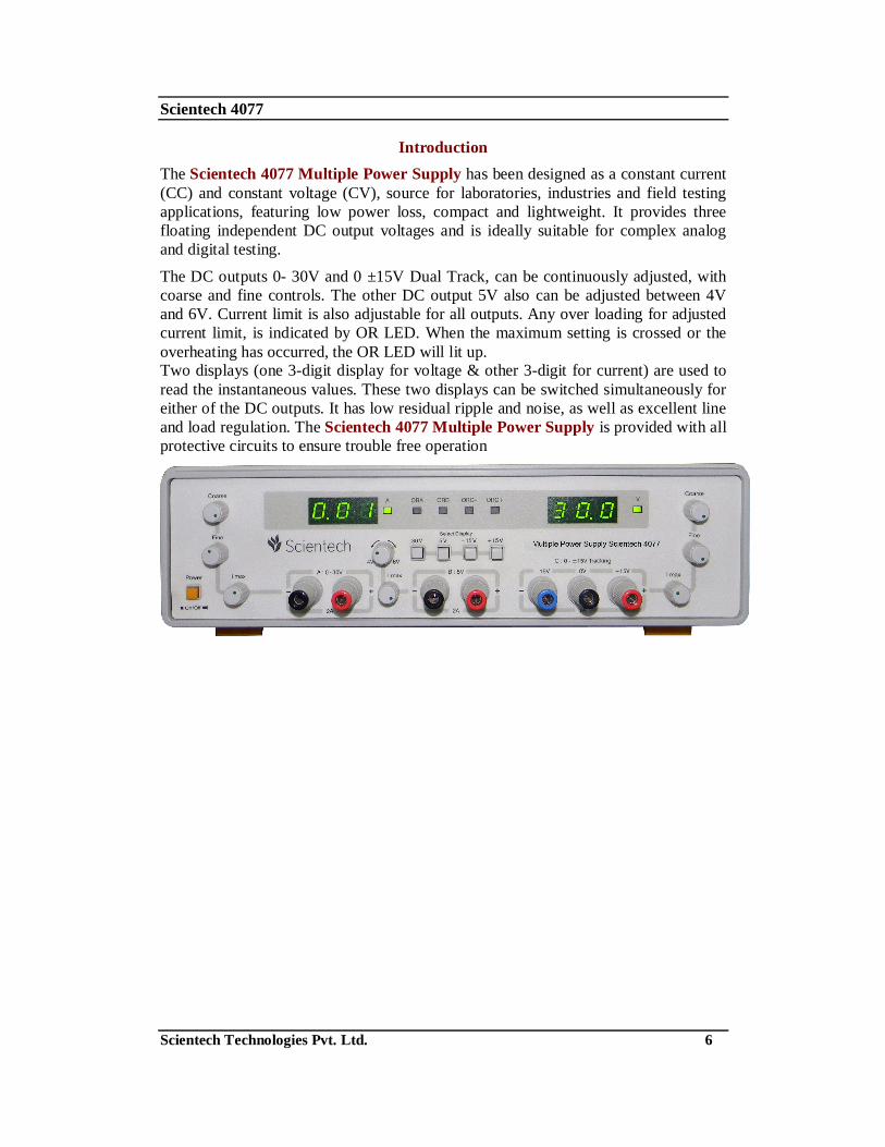
IntroductionThe Scientech 4077 Multiple Power Supply has been designed as a constant current(CC) and constant voltage (CV), source for laboratories, industries and field testingapplications, featuring low power loss, compact and lightweight. It provides threefloating independent DC output voltages and is ideally suitable for complex analogand digital testing.
The DC outputs 0- 30V and 0 ±15V Dual Track, can be continuously adjusted, withcoarse and fine controls. The other DC output 5V also can be adjusted between 4Vand 6V. Current limit is also adjustable for all outputs. Any over loading for adjustedcurrent limit, is indicated by OR LED. When the maximum setting is crossed or theoverheating has occurred, the OR LED will lit up.Two displays (one 3-digit display for voltage & other 3-digit for current) are used toread the instantaneous values. These two displays can be switched simultaneously foreither of the DC outputs. It has low residual ripple and noise, as well as excellent lineand load regulation. The Scientech 4077 Multiple Power Supply is provided with allprotective circuits to ensure trouble free operation
Scientech 4077
Scientech Technologies Pvt. Ltd. 7
Features
Three floating, independent DC supply voltages
DC OutputsA: 0 -30V, 2A
B: 5V, 2 Amps
C: 0 ± 15V (Dual Tracking) /1A each
Constant voltage and constant current operation
Short circuit protection
Digital display for voltage and current
Adjustable current limiter
Scientech 4077
Scientech Technologies Pvt. Ltd. 8
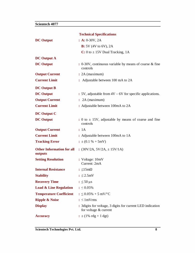
Technical SpecificationsDC Output : A: 0-30V, 2A
B: 5V (4V to 6V), 2AC: 0 to ± 15V Dual Tracking, 1A
DC Output ADC Output : 0-30V, continuous variable by means of coarse & fine
controlsOutput Current : 2A (maximum)
Current Limit : Adjustable between 100 mA to 2A
DC Output BDC Output : 5V, adjustable from 4V – 6V for specific applications.
Output Current : 2A (maximum)
Current Limit : Adjustable between 100mA to 2A
DC Output CDC Output : 0 to ± 15V, adjustable by means of coarse and fine
controls
Output Current : 1ACurrent Limit : Adjustable between 100mA to 1A
Tracking Error : ± (0.1 % + 5mV)
Other Information for all : (30V/2A, 5V/2A, ± 15V/1A)outputsSetting Resolution : Voltage: 10mV
Current: 2mAInternal Resistance : 15m
Stability : 2.5mV
Recovery Time : 50 sLoad & Line Regulation : 0.05%
Display : 3digits for voltage, 3 digits for current LED indicationfor voltage & current
Accuracy : ± (1% rdg + 1 dgt)
Scientech 4077
Scientech Technologies Pvt. Ltd. 9
General Information:Built in over voltage, overload, overheat & short circuit protection.
All outputs are floating.
Insulation:Between chassis and : > 10 M at 100VDCoutput terminal
Between chassis : > 50 M at 500VDCand AC plugPower Supply : 230V AC ± 10% 50Hz
Operating Conditions : 0 - 400 C; 90% RH
Dimension : W 285 x H 75x D 385 mmWeight : 5.5 Kgs. (approximately)
(Subject to Change)
Scientech 4077
Scientech Technologies Pvt. Ltd. 10
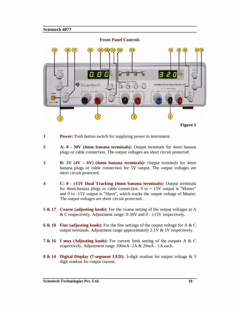
Front Panel Controls
Figure 1
1 Power: Push button switch for supplying power to instrument.
2 A: 0 - 30V (4mm banana terminals): Output terminals for 4mm bananaplugs or cable connection. The output voltages are short circuit protected.
3 B: 5V (4V – 6V) (4mm banana terminals): Output terminals for 4mmbanana plugs or cable connection for 5V output. The output voltages areshort circuit protected.
4 C: 0 - ±15V Dual Tracking (4mm banana terminals): Output terminalsfor 4mm.banana plugs or cable connection. 0 to + 15V output is "Master"and 0 to -15V output is "Slave", which tracks the output voltage of Master.The output voltages are short circuit protected. .
5 & 17 Coarse (adjusting knob): For the coarse setting of the output voltages at A& C respectively. Adjustment range: 0-30V and 0 - ±15V respectively.
6 & 18 Fine (adjusting knob): For the fine settings of the output voltage for A & Coutput terminals. Adjustment range approximately 2.1V & 1V respectively.
7 & 16 I max (Adjusting knob): For current limit setting of the outputs A & Crespectively. Adjustment range 100mA -2A & 20mA - 1A each.
8 & 14 Digital Display (7-segment LED): 3-digit readout for output voltage & 3digit readout for output current.
Scientech 4077
Scientech Technologies Pvt. Ltd. 11
9 4V – 6V: Adjustment for setting the output voltage of the source B from 4Vto 6V.
10 & 15 V & A Indicators: Two LEDS indicate the unit of the display.
11 I max: For current limit setting of the output B Adjustment range 100mA -2A.
12 Select Display (Push Buttons): Four push buttons can be pressed one at atime. When pressed each selects both displays (Voltage & Current)simultaneously for the respective voltage source to show the instantaneousvalues.
13 ORA, ORB, ORC-, ORC+ (Overload indicators): LEDs for overloadindication for respective DC outputs are provided. In case of overheating oroutput current in excess of set limit corresponding OR LED lits up.
Scientech 4077
Scientech Technologies Pvt. Ltd. 12
Operating Instructions
General Information:The logical front panel layout of Scientech 4077 makes it easy to become familiarwith the operation of the instruments. However, even experienced users should readthe following instructions thoroughly before using the instrument.After unpacking the instrument, check for any mechanical damage or loose partsinside. Should there be any transportation damage, inform the supplier immediatelyand do not put the instrument into operation.Safety:The case chassis and all measuring parts are connected to the protective earth contactof the inlet. The mains plug shall only be inserted in a socket outlet provided with aprotective earth contact. The protective action must not be negated by the use of anextension cord without a protective Conductor.Warning !Any interruption of the protective conductor inside or outside the instrument ordisconnection of the protective earth terminal is likely to make the instrumentdangerous. Intentional interruption is prohibited. The mains/line plug should beinserted before connections are made to measuring circuits.When removing the metal case or replacing, the instrument must be completelydisconnected from the mains supply. If any measurement or calibration procedures areunavoidable on the opened-up instrument, these must only be carried out by qualifiedpersonnel acquainted with the danger involved.Operating Conditions:The ambient temperature range during operation should be between 0° - 40°C; 90%RH and should remain within -20°C & + 70°C during transportation or storage. Theoperational position is optional; however, the ventilation holes on the Scientech 4077must not be obstructed. Prior to calibration a preheat run of approximately 30 minutesis required.First Time Operation:After unpacking the instrument check for any mechanical damages. The instrumentshould be plugged in mains-plug of proper mains supply 230V ± 10%. Switch on theinstrument. The power ‘On’ is indicated by lighting of displays.Operation:The Multiple Power Supply Scientech 4077 has three electrically isolated supplyvoltages. This permits easy series connection of output voltages. In case of seriesconnection the maximum output voltage increases with a maximum current of 2Amp.In the dual tracking supply, the negative (slave) Power Supply tracks the positive(master) supply voltage with 1% tracking error. The current limit setting is alsocommon for both due to overload, if "Master" output voltage falls. The "Slave" willtrack it. But if "Salve" gets overloaded "Master" will not track the "Slaves" outputvoltage.
Scientech 4077
Scientech Technologies Pvt. Ltd. 13
Functional ChecksThe Scientech 4077 should regularly be tested to assure proper functioning. Thefollowing test checks out the power supplies performance and suggestions foradjusting specific values. The adjustment will only be meaningful if the belowindicated or equivalent instruments are used. Prior to the functional test or adjustment,the instrument should be on for at least 30 minutes.
Measuring Instruments required:1. 4 ½ Digit DMM
2. 20 MHz Oscilloscope e.g. Scientech model 201
3. Rheostat: 100 - 2A and 17 - 5.5A.
Test Procedure:A. 0.30V DC output1. Check of maximum DC output voltage: Set the Coarse and Fine knobs to
maximum, the maximum DC output reading should be between 31V and 33V.This also can be verified on DMM.
2. Check of minimum DC output voltage: Set the Coarse and Fine knobs tominimum, the minimum DC output reading should be 00.0 Volts, which whenmeasured on DMM will be approximately 25mV. For load resistor of < 10K .
3. Check of minimum current limit setting: Set 30VDC output to 10V & shortcircuit the output terminals. Adjust current limit knob I maximum to minimumthe reading on the display should be <100mA.
4. Check of maximum output current: Set the DC output voltage to 10V. Short-circuit the output terminals. Adjust the I max current limit knob to maximum,the reading on the display, should be between 2.01A and 2.2A.
5. Check of over load indicators: Set the instrument as in step 3 or 4. When theoutput terminals are short circuited, "ORA" LED should lit.
6. Check of residual ripple and noise: Connect any load on DC output 0-30 V,and adjust the I max, to maximum (maximum to 2000 mA), and check the rippleand noise on DMM. It should not be more than 1mVrms.
B. 5V DC output:
1. Check of maximum DC output voltage: Set 4V-6V knob to maximum themaximum DC output voltage should be 5.5V, when measured on the DMM.
2. Check of minimum DC output voltage: Set 4V – 6V knob to minimum Theminimum DC output voltage should be 4.0 V, when measured on DMM.
3. Check of maximum output current: Set the current limit knob "I maximum"to 5V maximum Short circuit the output terminals. The reading on the currentdisplay should be 2.10A
Scientech 4077
Scientech Technologies Pvt. Ltd. 14
4. Check of minimum output current: Set the current limit knob "I maximum" tominimum Short circuit the output terminals. The reading on the current displayshould be 100mA.
5. Check of over load indicators: When the output terminals are short circuited,the beeper should start beeping and OR LED should lit.
6. Check of residual ripple and noise: Connect a suitable load, so that 2Ampcurrent flows through it check the ripple and noise on the Oscilloscope, it shouldbe less than 1mVrms.
C. 0 - ± 15V Dual Tracking output:1. Check of maximum DC output voltage: Set the Coarse and Fine knobs of this
section to maximum Select display for + 15V, then -15V. The maximum outputvoltage reading should be between 15.5 V and 16.5V in both + 15V & -15Vsections, which also can be verified on DMM.
2. Check of minimum DC output voltage: Set the Coarse and Fine knobs of thissection to minimum the minimum DC output reading should be 00.0 V for both+15V & -15V, which when measured on DMM will be < 25 mV for loadresistor of <10K .
3. Check of maximum tracking error: Set 0 to +15V output to maximum by the"Coarse & Fine" Controls. Now Check that difference between output voltagesat positive and negative output terminals (with respect to common) is not morethan 0.15V.
4. Check of minimum current limit setting: Set the output to ± 10V. Adjust thecurrent limit knob I maximum to minimum Short circuit all the three terminalsof this section. Select display for + 15V section then for -15V section. Thereading on the display should be 100mA.
5. Check of maximum output current: Set the output to ±10V. Adjust the currentlimit knob I maximum to maximum Short circuit all the three terminals of thissection. Select display for + 15V section then for-15V section. The reading onthe display should be between 1.01A and 1.1A in both cases.
6. Check of over load indicators: When, +, terminal is shorted to commonterminal, the "ORC+" LED should lit. When '-' terminal is shorted to commonterminal, the "ORC-" LED should lit.
7. Check of residual ripple and noise: Set the I maximum, to maximum Connecttwo equal loads of any value to both '+' and '-' outputs with respect to commonterminal. Check the ripple and noise on DMM. It should not be more than1mVrms in both the sections.