EEE 309 Communication Theory Semester: January 2017 Semester: January 2017 Dr. Md. Farhad Hossain Associate Professor Department of EEE, BUET Department of EEE, BUET Email: [email protected]Office: ECE 331, ECE Building
Transcript
EEE 309 Communication TheorySemester: January 2017Semester: January 2017
M lti l i dMultiplexing and Multiple AccessMultiple Access
TechniquesTechniques
2
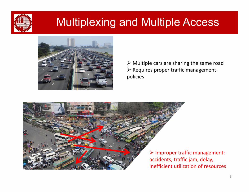
Multiplexing and Multiple Access
Multiple cars are sharing the same road Requires proper traffic management policies
Improper traffic management:
3
accidents, traffic jam, delay, inefficient utilization of resources
Multiplexing and Multiple Access (MA)
Multiple users shares the same channel Multiple users under a single base station
Multiplexing: Multiplexing technique combine signals from several sources Thus allows one channel to be used by multiple sources to send multiple messages without Thus allows one channel to be used by multiple sources to send multiple messages without interfering each other It works on the physical layer (L1) of OSI model
M lti l A (MA)Multiple Access (MA):Decides on - Who will transmit? Whom to transmit? When to transmit? How to transmit? MA techniques are channel access methods based on some principles including multiplexing All t h l t diff t d l h dl th it ti h th
4
Allocates channels to different users and also handles the situation when there are more message sources than available channels It works on the data link layer (L2) of OSI model
Multiplexing Techniques Multiplexing techniques allow sharing a channel by keeping the transmitted signals from various sources separate so that they do not interfere with one another
This separation is accomplished by making the signals orthogonal to one another This separation is accomplished by making the signals orthogonal to one another in the dimensions of frequency, time, code, space, etc.
Various types: Time division multiplexing (TDM) Frequency division multiplexing (FDM) Frequency division multiplexing (FDM) Wavelength division multiplexing (WDM) Code division multiplexing (CDM) Space division multiplexing (SDM) Orthogonal frequency division multiplexing (OFDM): a variety of FDM Polarization division multiplexing (PDM)
5
Polarization division multiplexing (PDM)
FDM
P
t
3D view
fSub-channel NSub-channel 2Sub-channel 1
Channel
User 1 User 2 User N
2D view
Available bandwidth of the common channel is divided into bands Signals are orthogonal (separated) in frequency domain
6
Requires guard bands to avoid adjacent-channel interference Requires filtering to minimize adjacent channel interference: costly
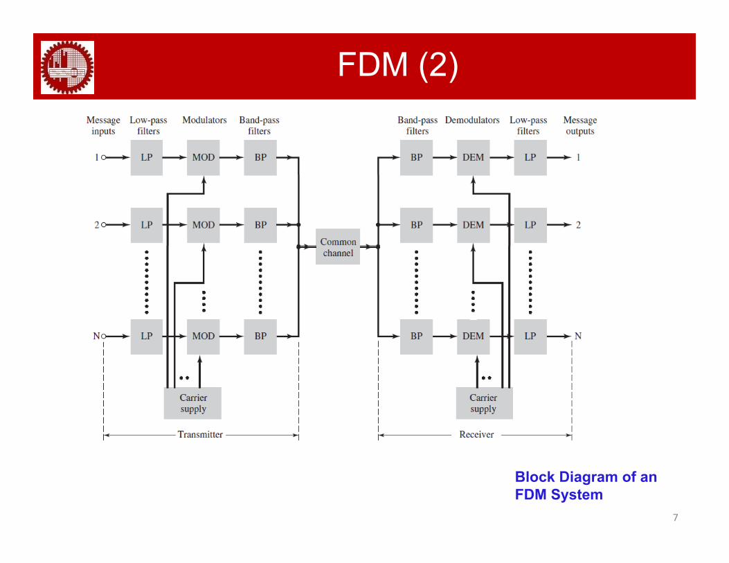
FDM (2)
7
Block Diagram of an FDM System
TDM (1)
A digital transmission technology
Transmission time is divided into time-slots and unique time slot(s) are allocated to q ( )each user
Different users can transmit or receive messages, one after the next in the same bandwidth but in different time slots: Orthogonal in time-domain
8
g
TDM (2)Block Diagram of a TDM System
Increases the transmission efficiency (i.e., better resource utilization) P it th tili ti f ll th d t f di it l t h i di it l h Permits the utilization of all the advantages of digital techniques: digital speech interpolation, source coding, channel coding, error correction, bit interleaving, etc. Suitable for asymmetric (i.e., unequal uplink and downlink data rate) data rate E i t i b i i i l h Equipment is becoming increasingly cheaper
Requires a significant amount of signal processing for synchronization as the t i i f ll t b tl h i d
9
transmission of all users must be exactly synchronized Requires guard times between time slots to compensate clock instabilities and transmission time delay
Example 1Following figure shows synchronous TDM with a data stream for each inputand one data stream for the output. The unit of data is 1 bit. Find (a) the inputbit duration, (b) the output bit duration, (c) the output bit rate, and (d) theoutput frame rateoutput frame rate.
a. The input bit duration is the inverse of the bit rate: 1/1 Mbps = 1 μsp p μb. The output bit duration is one-fourth of the input bit duration, or 1/4 μsc. The output bit rate is the inverse of the output bit duration, i.e., 4 Mbpsd The frame rate is always the same as any input rate So the frame rate is 1 000 000
12School of Electrical and Information Engineering
d. The frame rate is always the same as any input rate. So the frame rate is 1,000,000 frames per second
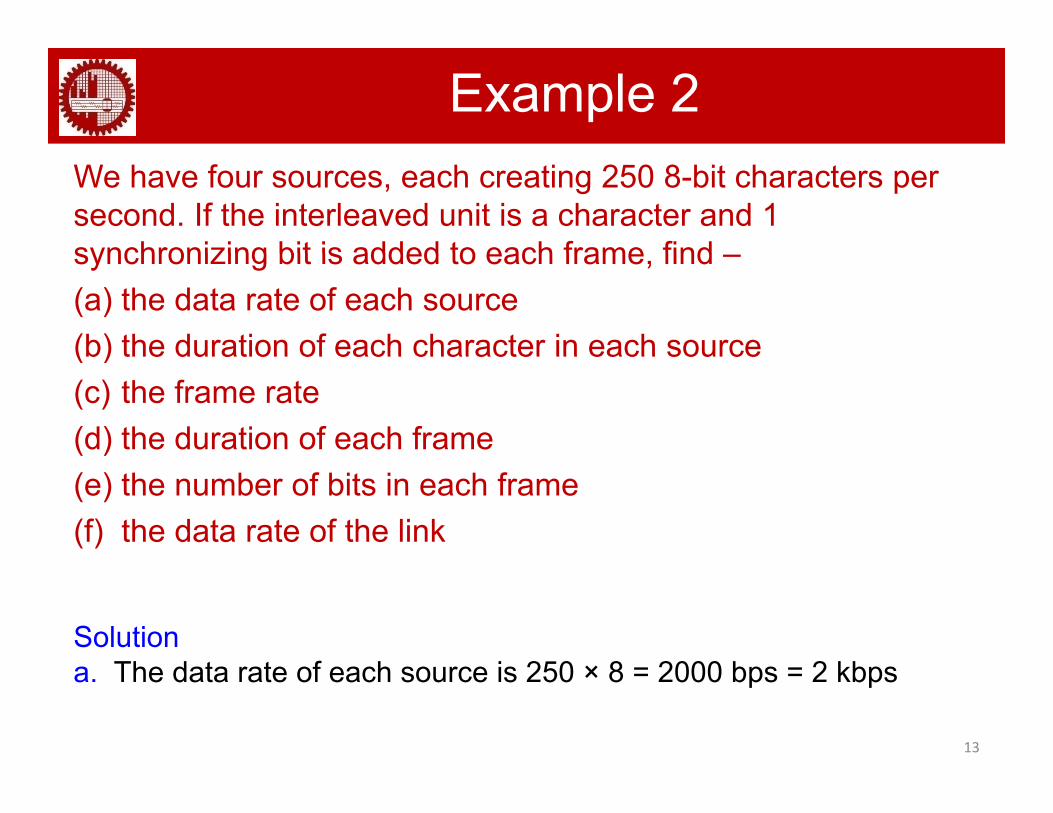
Example 2We have four sources, each creating 250 8-bit characters per second. If the interleaved unit is a character and 1 synchronizing bit is added to each frame findsynchronizing bit is added to each frame, find –(a) the data rate of each source(b) the duration of each character in each source(b) the duration of each character in each source(c) the frame rate(d) the duration of each frame(e) the number of bits in each frame(f) the data rate of the link
SolutionTh d t t f h i 250 8 2000 b 2 kb
13
a. The data rate of each source is 250 × 8 = 2000 bps = 2 kbps
Example 2b. Each source sends 250 characters per second. Therefore,
the duration of a character is 1/250 s, or 4 ms.
c. Each frame has one character from each source, which means the link needs to send 250 frames per second to k th t i i t f hkeep the transmission rate of each source.
d. The duration of each frame is 1/250 s, or 4 ms. Note that the duration of each frame is the same as the duration of eachduration of each frame is the same as the duration of each character coming from each source.
e Each frame carries 4 characters and 1 extra synchronizinge. Each frame carries 4 characters and 1 extra synchronizing bit. This means that each frame is 4 × 8 + 1 = 33 bits
f 33 bits are transmitted in 4 ms Hence the data rate = 33 x
14
f. 33 bits are transmitted in 4 ms. Hence the data rate = 33 x 1000 /4 = 8250 bps
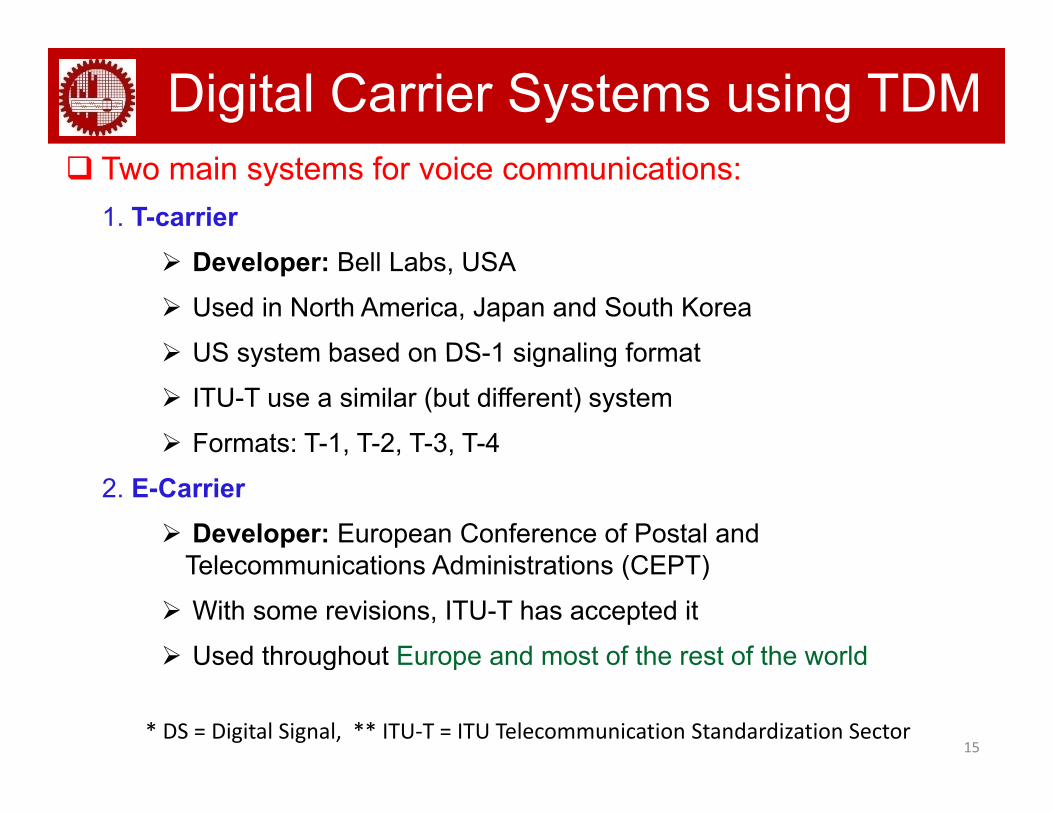
Digital Carrier Systems using TDM Two main systems for voice communications:
1. T-carrier D l B ll L b USA Developer: Bell Labs, USA Used in North America, Japan and South Korea US system based on DS-1 signaling format US system based on DS-1 signaling format ITU-T use a similar (but different) system Formats: T-1, T-2, T-3, T-4
2. E-Carrier Developer: European Conference of Postal and
Telecommunications Administrations (CEPT)Telecommunications Administrations (CEPT) With some revisions, ITU-T has accepted it Used throughout Europe and most of the rest of the world
15
Used throughout Europe and most of the rest of the world
* DS = Digital Signal, ** ITU‐T = ITU Telecommunication Standardization Sector
T-Carrier (1) 24 channels per frame 1 bit per frame (The first bit of a frame) is framing bit used for
synchronizationsynchronization 8 kHz sampling rate and 8 bits/sample = 64 kbps per channel Uses μ-law with μ = 255
16
T-1 Lines for Multiplexing Telephone Lines
T-Carrier (2)T-1 Frame Structure
(Frame duration: 125 µs)(Bit duration: 0.6477 µs)
17
T-Carrier (3) Can also interleave DS-1 channels:
For example, DS-2 is four DS-1 giving 6.312 Mbps
18
E-Carrier (1) E-Carrier system multiplexes 32 DS-0 channels (time slots
each carrying 8 bits) together to form an E-1 circuit Ti l t 0 i d t d t t i i t d ti Time slot 0 is devoted to transmission management and time
slot 16 for signaling The rest slots are assigned for voice/data transport The rest slots are assigned for voice/data transport Data rate: 32*8*8 kbps = 2.048 Mbps Uses A-law
19** DS = Digital Signal
E-Carrier (2)
20
E-Carrier (3)
21
Joint TDM and FDM For certain applications, such as synchronous optical network (SONET) or synchronous digital hierarchy (SDH), both TDM and FDM can be employed simultaneously
22
WDM Block Diagram of an
WDM System
Conceptually same as FDM, except that multiplexing and demultiplexing involves light signals transmitted through fibre-optic channels
23
Combines different frequency signals (same as FDM). However, the frequencies are very high.
WDM is designed to utilize the high data rate capability of fibre-optic cable
Multiple Access (MA) Techniques Decides on - who will transmit? whom to transmit? when to transmit? How to transmit?
Random access (contention methods): No station is superior to another station and none is assigned the control over another. No station permits, or does not permit, another station to send.
Controlled access: The stations consult one another to find which station has the right to send. A station cannot send unless it has been authorized by other stations.
24
Channelization techniques: The available bandwidth of a link is shared in time, frequency, or through code, between different stations. Usually, it is controlled by a system administrator.
Multiple Access (MA) Techniques Various forms of channelization techniques:
Frequency division multiple access (FDMA): e g 1G cellular system Frequency division multiple access (FDMA): e.g., 1G cellular system
Time division multiple access (TDMA) : e.g., 2G GSM system
Orthogonal frequency division multiple access (OFDMA): e.g., LTE, WiMAX
Space division multiple access (SDMA)
25
These techniques can be used in combination
Case Study: GSM TDMA Frames
Hyperframe
Superframe
Frame
Multiframe
Frame
Bursts
26
CDMA A spread spectrum (SS) multiple access technique, which allows multiple signals occupying the same bandwidth to be transmitted simultaneously without interfering with one another
In a CDMA system, each user is assigned a particular code, named as pseudo-noise (PN) code which are ideally supposed to be unique for each usercode, which are ideally supposed to be unique for each user
This unique code enables the desired message to be extracted at the receiver
The transmissions from other users looks like interference
What is a spread spectrum (SS) system?What is a spread spectrum (SS) system?
Spreads a narrowband communication signal over a wide range of frequencies
Si l di i d b f t i i b i
PowerNarrowband
(High Peak Power)
Signal spreading is done before transmission by using a spreading sequence
De-spreads it into the original data bandwidth at the receiver
Spread Spectrum(Low Peak Power)
27
receiver
Same sequence is used at the receiver to retrieve the signal
Frequency
FDMA, TDMA and CDMA
28
CDMA: Principle (1)Two types: Direct sequence CDMA (DS-CDMA) Frequency hoping CDMA (FH-CDMA)
DS-CDMA System:1 0 1
Datab(t)
Symbol Duration TSBit duration Tb
Datad(t) 0b(t)
PNSequence
a(t)
d(t)
PN sequence
c(t)
PowerNarrowband
b(t)
a(t)
b(t)a(t)
c(t)
d(t)c(t)
b(t)a(t)
( )
Spread SpectrumTime
Chip Duration T
( ) ( )
29Processing gain, G = No. of chips per bit = Tb/TcFrequency
Chip Duration TC
CDMA System
Modulator
Spreaded signal foruser 1, bS1
Data of Modulator
PN code ofUser 1
user 1, b1PN 1
Transmitted signal of user 1, TX1
Input Signal ofReceiver 1 beforeDespreading, bS1'
Modulator
PN 2
Transmitted signal of user 2, TX2
Data ofuser 2, b2
Demodulator
PN d f
Output ofReceiver 1, b1'
bS2 Despreading
p g, S1
PN 1
PN code ofUser 2
PN code ofUser 1
bSK Receiver
Modulator
PN code ofUser K
PN NTransmitted signal
of user K, TXK
Data ofuser 2, bK
30Transmitter
CDMA: Principle (2)
31
CDMA: Principle (3)
PN code
32
CDMA: Principle (4)
33
CDMA: Principle (5)Detection by receiver (station) 2:
34
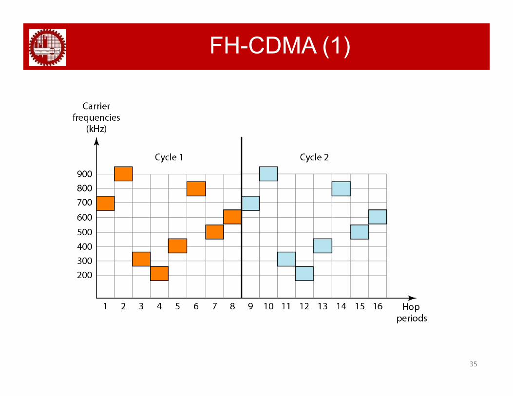
FH-CDMA (1)
35
FH-CDMA (2)
Transmitter
36
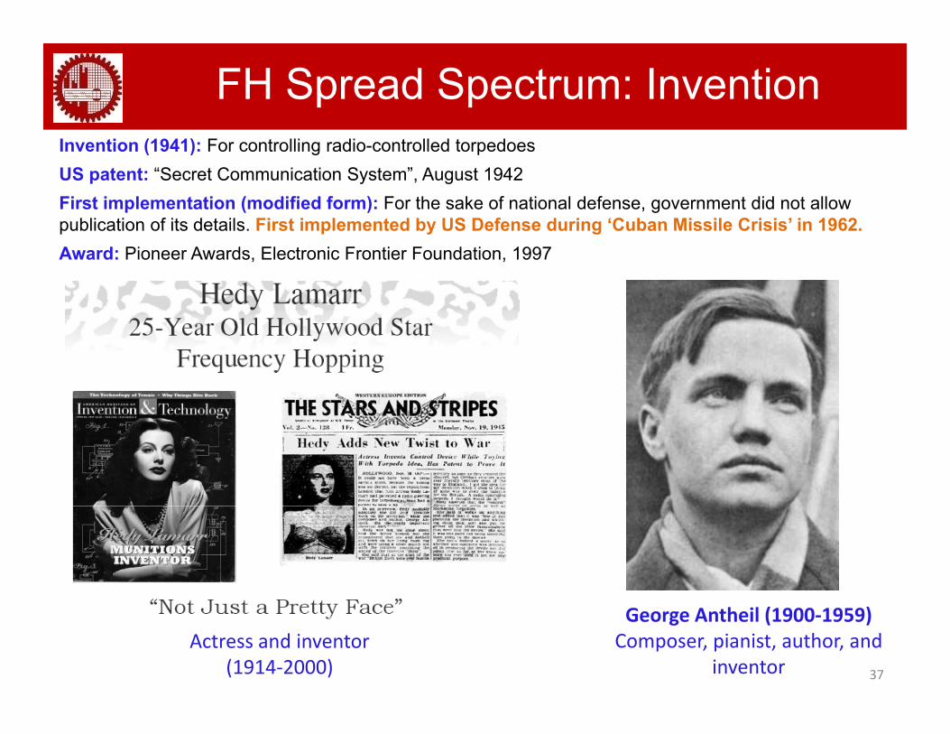
FH Spread Spectrum: InventionInvention (1941): For controlling radio-controlled torpedoesUS patent: “Secret Communication System”, August 1942 First implementation (modified form): For the sake of national defense, government did not allow publication of its details First implemented by US Defense during ‘Cuban Missile Crisis’ in 1962.publication of its details. First implemented by US Defense during Cuban Missile Crisis in 1962.Award: Pioneer Awards, Electronic Frontier Foundation, 1997
37
George Antheil (1900‐1959) Composer, pianist, author, and
inventorActress and inventor
(1914‐2000)
CDMA: AdvantagesSome of the advantages:
Hard to intercept: secure communications
Difficult to jam
Improved interference rejection and suppression
No guard-band like FDMA or guard-time like TDMA
Easy addition of more users
Can accommodate more users than TDMA and FDMA Can accommodate more users than TDMA and FDMA
Improved multi-path effect mitigation
Graceful degradation of performance as the number of simultaneous Graceful degradation of performance as the number of simultaneous users increases
Less susceptible to effects induced from a changing environment
38
CDMA: Drawbacks Requires high bandwidth
Self-jamming problem due to spreading sequences not being exactly orthogonalorthogonal
Power control necessary for mitigating near-far problem
Inappropriate for ultra high rate wireless access because pp p g
Tremendous width of BW necessary
Hardware complexity
Synchronization problem
39
DuplexingDuplexing refers to the technique of separating the transmitting and receiving channels
Communication Systems: Simplex, Half‐duplex, Full‐duplex
Transmitter and receiver operate at different carrier frequencies
p g ( )Transmitter and receiver operate at
same carrier frequencies, but through different time‐slots
MA and Duplexing Schemes in Use
System Multiple Access
(Don’t need to memorize the followings for exam)
Advanced Mobile Phone System (AMPS) FDMA/FDD
2G Global System for Mobile (GSM) TDMA/FDDy ( )
US Digital Cellular (USDC) TDMA/FDD
Digital European Cordless Telephone (DECT) FDMA/TDD
US Narrowband Spread Spectrum (IS-95) CDMA/FDD
Satellite Communication TDMA, FDMA, CDMA
3G WCDMA/FDD3G WCDMA/FDD
LTE OFDMA/FDD or TDD
WiMAX OFDMA/FDD or TDD
41
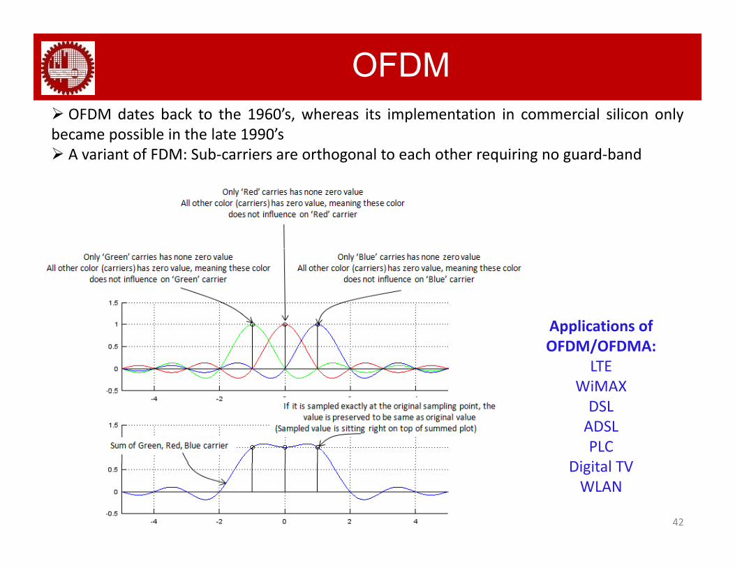
OFDM OFDM dates back to the 1960’s, whereas its implementation in commercial silicon onlybecame possible in the late 1990’s A variant of FDM: Sub‐carriers are orthogonal to each other requiring no guard‐band