103Q-3 P.O. Box 4638 Houston, Texas 77210-4638 ISSUE: September 20, 2006 Multiplex Plunger Pumps Installation, Care and Operation Manual 101T-4 Covering the following pumps: 101T-4 133T-4 163Q-4 217Q-4 163Q-4 Sales / Technical Information USA Tollfree: 1 (800) 324-4706 Phone: 1 (918) 447-4600 Fax: 1 (918) 447-4677 Internet: http://www.nov.com 133T-4 217Q-4
Transcript
103Q-3
P.O. Box 4638 Houston, Texas 77210-4638 ISSUE: September 20, 2006
Multiplex Plunger Pumps Installation, Care and Operation Manual
101T-4
Covering the following pumps: 101T-4 133T-4 163Q-4 217Q-4
163Q-4
Sales / Technical Information USA Tollfree: 1 (800) 324-4706 Phone: 1 (918) 447-4600 Fax: 1 (918) 447-4677 Internet: http://www.nov.com
133T-4
217Q-4
SUPPLEMENT FOR ALL PUMP MANUALS
! WARNING !
PRESSURE
RELIEF
VALVES
! NOTICE ! Our technical publications relative to reciprocating pumps state that pressure relief valves must be installed in the discharge systems from these units. This supplement is issued to emphasize the importance of relieving the discharge system of all pressure which exceeds the rated working pressure applied by the manufacturer to the specific pistons and liners (or plungers and packing) in any particular unit.
! WARNING ! For the protection of persons and property the discharge system from each Reciprocating Pump must be equipped with a device which relieves the system of all pressures which exceed the pressure rating applied by the manufacturer to each particular piston or plunger diameter. Allowances will be made for pressure surges which are inherent with the reciprocating action of piston and plunger pumps. The percentage of pressure allowance appears later in this publication and in the “Standards of the Hydraulic Institute” (13th edition). The relieving device must provide for instantaneous pressure relief, it may be a valve designed for automatic or manual resetting; however, if preferred, rupture discs or burst discs may be installed. FAILURE to comply with the procedures outlined in the Warning may result in damage to the pump and related equipment and more importantly may cause serious bodily injury or death!
THE PRESSURE RELIEF VALVE: 1. This valve must be a full opening type. 2. It must have a working pressure rating, equal
to or greater than, the maximum working pressure of the pump.
3. The through capacity of the valve, when fully
opened, must be sufficient to relieve the full capacity of the pump without excessive overpressure.
RUPTURE DISC OR BURST DISC:
1. These discs must have a diameter which is
not less than the pipe size of the pressure relief flange.
2. These discs must have a rupture or burst
pressure rating consistent with the specifications tabulated later in this publication.
LOCATION OF THE RELIEF VALVE:
1. The relief valve must be placed in the
discharge line as close as possible to the pump fluid end or it may be mounted on the pump discharge manifold.
2. The relief valve must be on the pump side of
any discharge strainer.
3. The relief valve must be between the pump
fluid end and any valve in the discharge system.
4. There must be no restricting device(s)
between the relief valve and the pump fluid end.
THE RELIEF VALVE DISCHARGE LINE:
1. The relief valve discharge line should not
terminate in the pump suction line. 2. The line should terminate in the supply tank,
if possible. 3. The line must be securely anchored. 4. The line must be the same pipe size as, or
may be larger than, the discharge connection on the relief valve.
5. If the line is of great length, this must be
taken into consideration in sizing the relief valve.
6. There must be no restrictions or valves in the
relief valve discharge line.
NOTE: Follow the foregoing instructions if rupture discs or burst discs are installed.
SUGGESTED SET PRESSURES FOR THE PUMP RELIEF VALVES:
PUMP TYPE: OPERATING PUMP PRESSURE: Double Acting – Duplex Piston Pressure Rating – Plus 25% Double Acting – Triplex Piston Pressure Rating – Plus 10% Double Acting – Quintuplex Piston Pressure Rating – Plus 10% Single Acting – Triplex Piston Pressure Rating – Plus 10% Single Acting – Simplex Plunger Pressure Rating – Plus 25% Single Acting – Duplex Plunger Pressure Rating – Plus 20% Single Acting – Triplex Plunger Pressure Rating – Plus 10% Single Acting – Quintuplex Plunger Pressure Rating – Plus 10% Single Acting – Septuplex Plunger Pressure Rating – Plus 10% Note: The above set pressures are to be observed when installing rupture discs or burst discs.
2
Installation, Care and Operation Manual
www.nov.com
Foreword…
This manual is published as a guide for the normal operation of your NATIONAL OILWELL VARCO equipment. Because of the many factors, which contribute to the function or malfunction of this machinery, and not having complete knowledge of each factor or combination of factors, we cannot detail all facets of this subject. We must therefore confine the scope of this presentation and when situations encountered are not fully encompassed by complete, understandable instructions, these situations must be referred to the manufacturer. When other than routine servicing is necessary, it can be most efficiently performed if the unit is removed to an area of adequate space where an over-head crane, hydraulic lift, bearing pullers, impact tools, etc., are accessible. The dimension and tolerances specified in this publication are those desirable for the most efficient operations of the equipment. When components become worn or when new parts are introduced into a worn unit, it may not be possible or economically feasible to reestablish such strict alignment and correct all dimensional deviations. Improvements in design, engineering, materials, production methods, etc., may necessitate changes in these products and result in inconsistencies between the content of this publication and the physical equipment. We reserve the right to make these changes without incurring any liability or obligation beyond that which is stipulated in the purchase contract. The pictures, photographs, charts, diagrams, drawings, verbal contents and specifications are not to be construed as giving rise to any warranty on the part of NATIONAL OILWELL VARCO. National Oilwell Varco makes no warranty, either expressed or implied beyond that which is stipulated in the purchase contract. NATIONAL OILWELL VARCO pumps are manufactured by National Oilwell Varco at the Tulsa, Oklahoma plant. The serial number, assigned each pump is stamped on the power end. Please refer to this serial number when ordering parts for the pump. The right and left sides of the pump are determined by viewing the pump from the back of the power end, looking toward the fluid end. This position is also used to identify the plungers and their related parts as being number one, two and three, beginning at the left side of the pump.
! CAUTION! CAUTION! CAUTION!
EXERCISE SAFETY IN ALL PERFORMANCES: DO NOT IGNORE ANY WARNINGS; USE ONLY APPROVED METHODS, MATERIALS AND TOOLS. DO NOT PERMIT ANY FUNCTION OF QUESTIONABLE SAFETY; ACCIDENTS ARE CAUSED BY UNSAFE ACTS AND UNSAFE CONDITIONS. SAFETY IS YOUR BUSINESS AND YOU ARE INVOLVED.
! WARNING! WARNING! WARNING!
BEFORE PERFORMING ANY SERVICE FUNCTION, BE CERTAIN THAT THE UNIT IS SEPARATED FROM ITS POWER SOURCE OR THAT THE POWER SOURCE IS LOCKED-OUT TO PREVENT ANY FORM OF ENERGY FROM ENTERING THE EQUIPMENT. THIS WOULD INCLUDE ELECTRICAL OR MECHANICAL ENERGY INTO OR FROM THE PRIME MOVER(S), PNEUMATIC ENERGY FROM THE COMPRESSOR/AIR SYSTEM, ETC.
3
Installation, Care and Operation Manual
www.nov.com
! WARNING ! WARNING ! WARNING ! FAILURE TO OBSERVE THE WARNINGS AND NOTES OF CAUTION IN THIS PUBLICATION CAN RESULT IN PROPERTY DAMAGE, SERIOUS BODILY INJURY, OR DEATH.
! ATTENTION - NOTICE - IMPORTANT !
THESE TERMS ARE USED TO DRAW ATTENTION TO ACTION THAT WILL CAUSE DAMAGE TO THE PUMP, COMPONENTS OR ATTACHMENTS.
! ATTENTION !
PUMP NOMENCLATURE: ALL PUMP SIZES WITHIN THIS MANUAL WILL BE DESCRIBED WITH THE NEW OR CURRENT NOMENCLATURE. THE OLD PUMP NOMENCLATURES DESCRIBED ON THE FRONT COVER, BUT NOT INCLUDED IN THIS MANUAL EXCEPT AS NEEDED, ARE TO BE UNDERSTOOD AS BEING INCLUDED WITH THE NEW NOMENCLATURES.
! WARNING ! WARNING ! WARNING !
BEFORE SERVICING PUMPS:
1. SHUT DOWN OR DISENGAGE THE PUMP POWER SOURCE. 2. SHUT DOWN ALL PUMP ACCESSORY EQUIPMENT. 3. RELIEVE OR "BLEED OFF" ALL PRESSURE FROM THE PUMP FLUID CYLINDER(S).
FAILURE TO SHUT DOWN POWER AND RELIEVE PRESSURE FROM THE PUMP BEFORE SERVICING CAN RESULT IN SERIOUS PERSONAL INJURY AND PROPERTY DAMAGE.
4
Installation, Care and Operation Manual
www.nov.com
Plunger Pump Nomenclature Example….
101 T- 4 M F RATED INPUT HORSEPOWER T = TRIPLEX Q = QUINTUPLEX F = FLANGED L = LOW PRESSURE M = MEDIUM. H = HIGH STROKE LENGTH (IN.)
5
Installation, Care and Operation Manual
www.nov.com
Table of Contents… INSTALLATION PAGE I. GENERAL A. Suction Line .....................................................................................................................................................8 B. Discharge Line ............................................................................................................................................. 8-9 C. Power End .......................................................................................................................................................9 D. Fluid End..........................................................................................................................................................9 E. Plunger Packing............................................................................................................................................ 10 F. Plunger Packing Lubrication ......................................................................................................................... 10 G. Suction Pulsation Dampener 1. Low Pressure - Plastic Body................................................................................................................... 10 2. High Pressure - Aluminum Body ............................................................................................................ 11 LUBRICATION I. GENERAL A. Oil.................................................................................................................................................................. 12
OPERATION I. GENERAL A. Operation Check List .................................................................................................................................... 13
MAINTENANCE I. GENERAL A. Daily Maintenance ........................................................................................................................................ 14 B. Monthly Maintenance.................................................................................................................................... 14 C. Storage ......................................................................................................................................................... 15 D. Start-Up After Storage .................................................................................................................................. 15 II. TROUBLE SHOOTING GUIDE...................................................................................................................... 16-18 OVERHAUL AND REPAIR I. GENERAL A. Tools Required.............................................................................................................................................. 19 B. Check Points and Adjustments 1. 101T-4 and 133T-4 ............................................................................................................................ 19-20 2. 163Q-4 and 217Q-4........................................................................................................................... 19-20 3. 101T-4, 133T-4, 163Q-4, and 217Q-4............................................................................................... 19-20
6
Installation, Care and Operation Manual
www.nov.com
Table of Contents (Continued)… DISASSEMBLY PAGE I. POWER END A. Plunger/Intermediate Rods and Oil Wiper Retainers.....................................................................................21 B. Crankshaft Assembly.....................................................................................................................................21 101T-4 and 133T-4 ................................................................................................................................ 21-22 163Q-4 and 217Q-4.....................................................................................................................................22 C. Crankshaft Bearings (All Pumps) ............................................................................................................ 22-23 D. Lubrication Oil Pump (133T-4 and 217Q-4) ............................................................................................ 24-25 E. Integral Gear Reducer ...................................................................................................................................26 II. FLUID END A. Fluid Cylinder Removal All Pumps.....................................................................................................................................................26 B. Plunger Removal All Pumps.....................................................................................................................................................27 C. Stuffing Box Removal ....................................................................................................................................27 D. Fluid End Valve Removal ..............................................................................................................................27
ASSEMBLY I. POWER END A. Connecting Rod and Crosshead Assembly 101T-4 and 163Q-4 .....................................................................................................................................28 133T-4 and 217Q-4 .....................................................................................................................................29 B. Crankshaft Main Bearings and Center Support Bearings 101T-4 and 133T-4 ................................................................................................................................ 30-31 163Q-4 and 217Q-4............................................................................................................................... 31-33 C. Connecting Rod to Crankshaft Assembly All Pumps.....................................................................................................................................................33 D. Intermediate Rods and Oil Seal Retainers All Pumps.....................................................................................................................................................34 II. FLUID END A. Stuffing Boxes and Plungers All Pumps.....................................................................................................................................................35 B. Power End/Fluid end Adapters All Pumps ................................................................................................................................................ 35-36 C. Fluid Cylinders All Pumps ......................................................................................................................................................36 D. Fluid Valves – Tapered Seat All Pumps.....................................................................................................................................................36 E. Piping Installation All Pumps.....................................................................................................................................................36 F. Plunger Packing Installation 1. 838 Packing ....................................................................................................................................... 37-38 2. Braided Packing................................................................................................................................. 39-41 3. 1068-4 Spring Loaded Packing ......................................................................................................... 41-42
7
Installation, Care and Operation Manual
www.nov.com
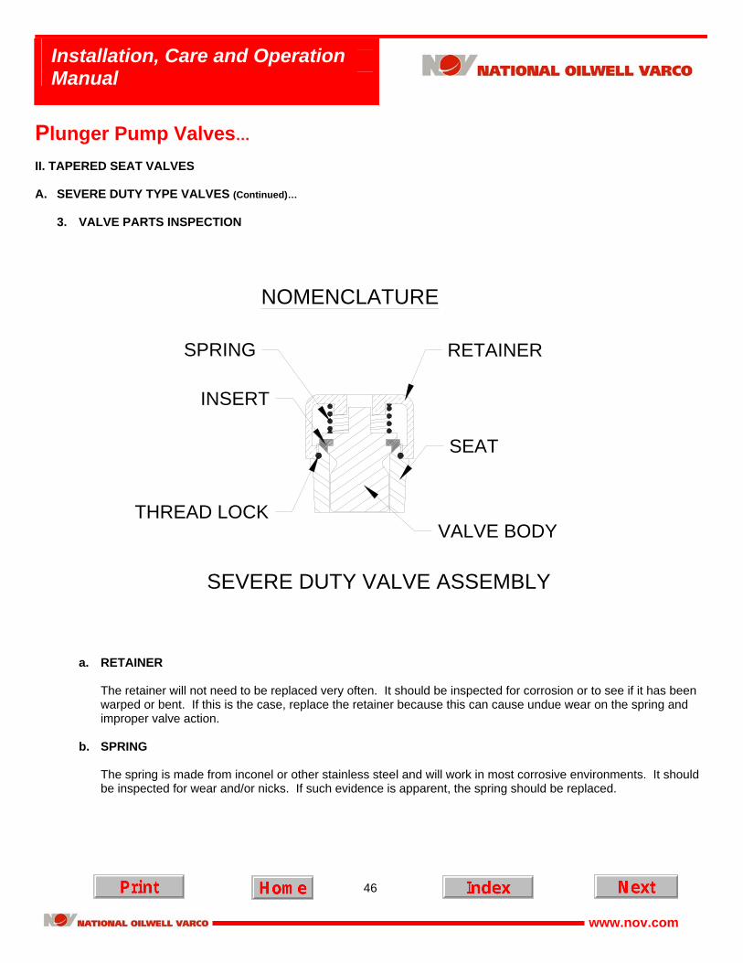
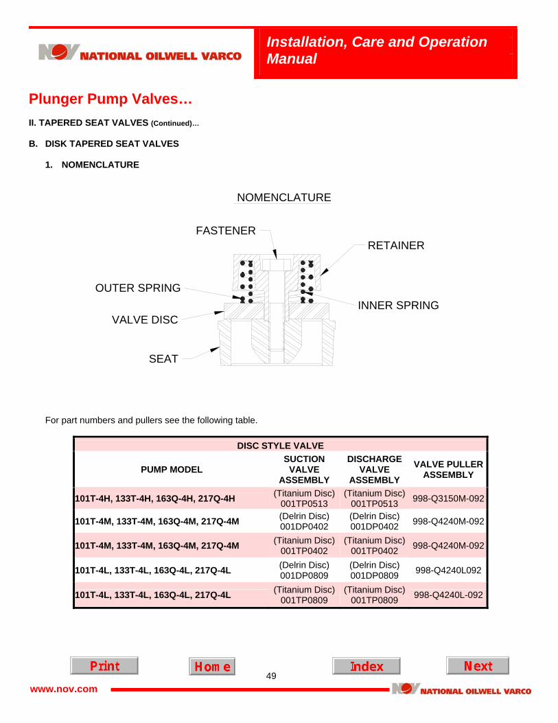
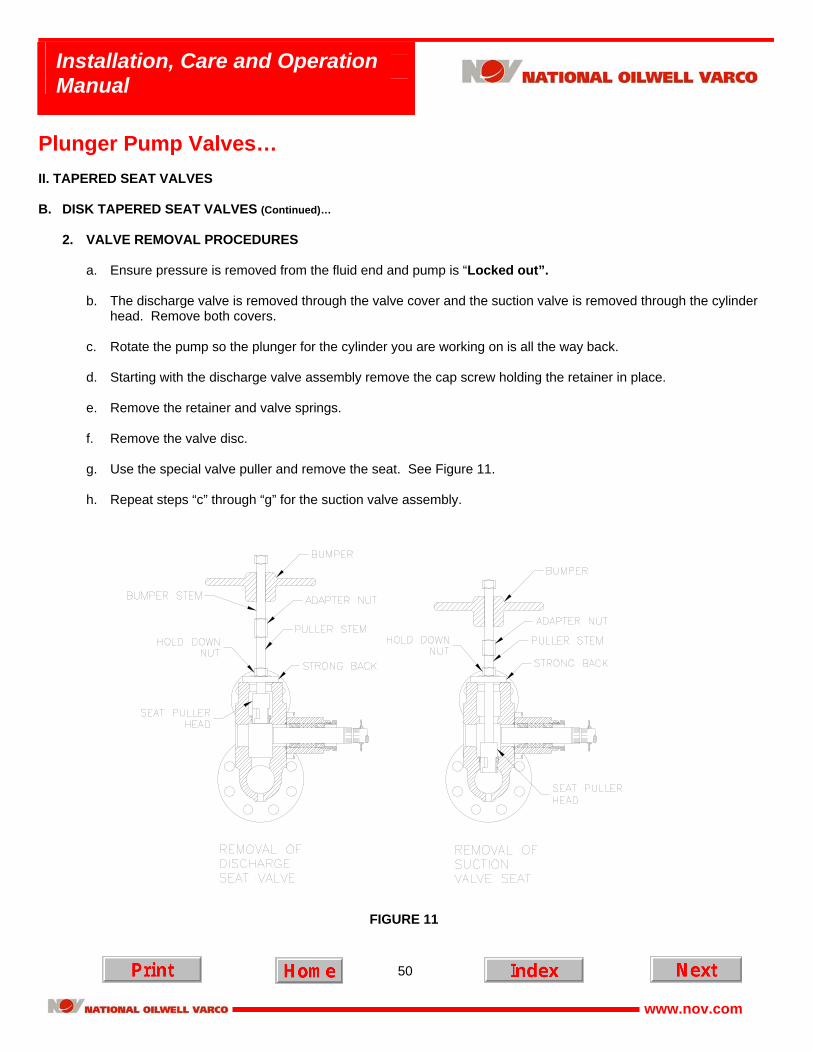
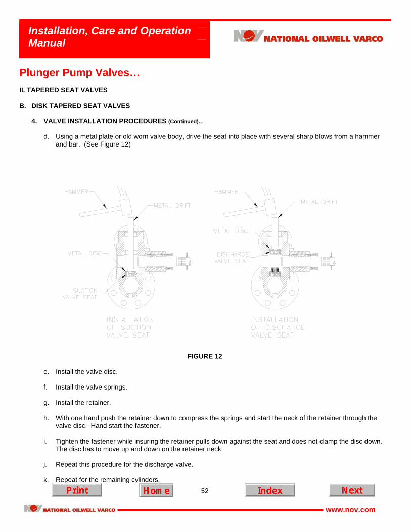
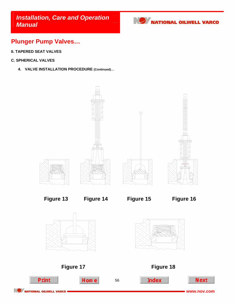
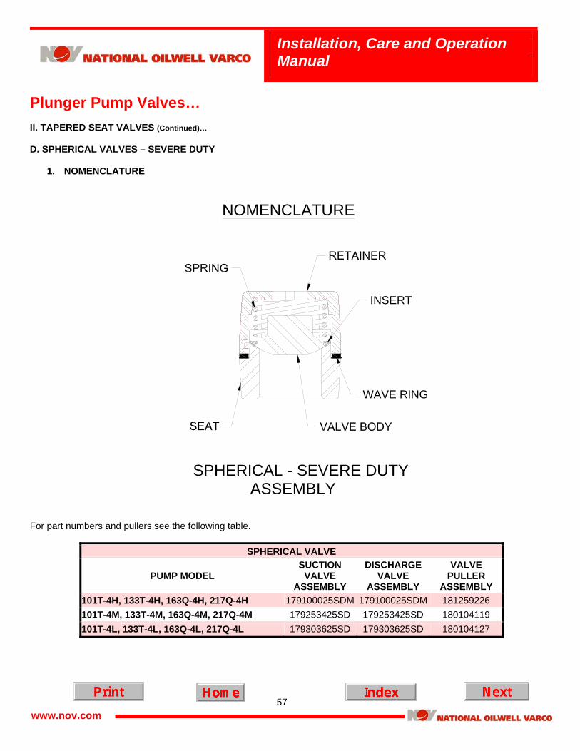
Table of Contents (Continued)… PLUNGER PUMP VALVES PAGE I. OPERATIONAL MAINTENANCE A. Suction and discharge ...............................................................................................................................................43 B. Valve Covers ..............................................................................................................................................................43 C. Valve Cover Seals .....................................................................................................................................................43 D. Valve Springs .............................................................................................................................................................43 E. Valve and Seat ...........................................................................................................................................................43 II. TAPERED SEAT VALVES A. Severe Duty Valve 1. Nomenclature ........................................................................................................................................................44 2. Valve Removal Procedure....................................................................................................................................45 3. Valve Inspection Procedure..................................................................................................................................46 4. Valve Installation Procedure ........................................................................................................................... 47-48 B. Disc Style Valve 1. Nomenclature ........................................................................................................................................................49 2. Valve Removal Procedure....................................................................................................................................50 3. Valve Inspection Procedure..................................................................................................................................51 4. Valve Installation Procedure ........................................................................................................................... 51-52 C. Spherical Valve 1. Nomenclature ........................................................................................................................................................53 2. Valve Removal Procedure....................................................................................................................................54 3. Valve Inspection Procedure..................................................................................................................................54 4. Valve Installation Procedure ........................................................................................................................... 55-56 D. Spherical Valve – Severe Duty 1. Nomenclature ........................................................................................................................................................57 2. Valve Removal Procedure....................................................................................................................................58 3. Valve Inspection Procedure............................................................................................................................ 58-59 4. Valve Installation Procedure .................................................................................................................................59
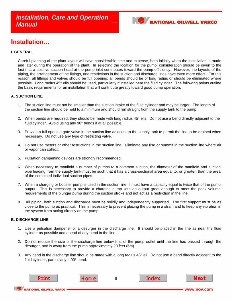
Installation… I. GENERAL Careful planning of the plant layout will save considerable time and expense, both initially when the installation is made
and later during the operation of the plant. In selecting the location for the pump, consideration should be given to the fact that a positive suction head at the pump inlet contributes toward the pump efficiency. However, the layouts of the piping, the arrangement of the fittings, and restrictions in the suction and discharge lines have even more effect. For this reason, all fittings and valves should be full opening; all bends should be of long radius or should be eliminated where possible. Long radius 45° ells should be used, particularly if installed near the fluid cylinder. The following points outline the basic requirements for an installation that will contribute greatly toward good pump operation.
A. SUCTION LINE
1. The suction line must not be smaller than the suction intake of the fluid cylinder and may be larger. The length of the suction line should be held to a minimum and should run straight from the supply tank to the pump.
2. When bends are required, they should be made with long radius 45° ells. Do not use a bend directly adjacent to the
fluid cylinder. Avoid using any 90° bends if at all possible. 3. Provide a full opening gate valve in the suction line adjacent to the supply tank to permit the line to be drained when
necessary. Do not use any type of restricting valve. 4. Do not use meters or other restrictions in the suction line. Eliminate any rise or summit in the suction line where air
or vapor can collect. 5. Pulsation dampening devices are strongly recommended. 6. When necessary to manifold a number of pumps to a common suction, the diameter of the manifold and suction
pipe leading from the supply tank must be such that it has a cross-sectional area equal to, or greater, than the area of the combined individual suction pipes.
7. When a charging or booster pump is used in the suction line, it must have a capacity equal to twice that of the pump
output. This is necessary to provide a charging pump with an output great enough to meet the peak volume requirements of the plunger pump during the suction stroke and not act as a restriction in the line.
8. All piping, both suction and discharge must be solidly and independently supported. The first support must be as
close to the pump as practical. This is necessary to prevent placing the pump in a strain and to keep any vibration in the system from acting directly on the pump.
B. DISCHARGE LINE
1. Use a pulsation dampener or a desurger in the discharge line. It should be placed in the line as near the fluid
cylinder as possible and ahead of any bend in the line. 2. Do not reduce the size of the discharge line below that of the pump outlet until the line has passed through the
desurger, and is away from the pump approximately 20 feet (6m). 3. Any bend in the discharge line should be made with a long radius 45° ell. Do not use a bend directly adjacent to the
fluid cylinder, particularly a 90° bend.
9
Installation, Care and Operation Manual
www.nov.com
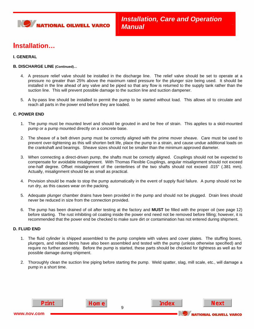
Installation… I. GENERAL B. DISCHARGE LINE (Continued)…
4. A pressure relief valve should be installed in the discharge line. The relief valve should be set to operate at a
pressure no greater than 25% above the maximum rated pressure for the plunger size being used. It should be installed in the line ahead of any valve and be piped so that any flow is returned to the supply tank rather than the suction line. This will prevent possible damage to the suction line and suction dampener.
5. A by-pass line should be installed to permit the pump to be started without load. This allows oil to circulate and
reach all parts in the power end before they are loaded.
C. POWER END
1. The pump must be mounted level and should be grouted in and be free of strain. This applies to a skid-mounted pump or a pump mounted directly on a concrete base.
2. The sheave of a belt driven pump must be correctly aligned with the prime mover sheave. Care must be used to
prevent over-tightening as this will shorten belt life, place the pump in a strain, and cause undue additional loads on the crankshaft and bearings. Sheave sizes should not be smaller than the minimum approved diameter.
3. When connecting a direct-driven pump, the shafts must be correctly aligned. Couplings should not be expected to
compensate for avoidable misalignment. With Thomas Flexible Couplings, angular misalignment should not exceed one-half degree. Offset misalignment of the centerlines of the two shafts should not exceed .015" (.381 mm). Actually, misalignment should be as small as practical.
4. Provision should be made to stop the pump automatically in the event of supply fluid failure. A pump should not be
run dry, as this causes wear on the packing. 5. Adequate plunger chamber drains have been provided in the pump and should not be plugged. Drain lines should
never be reduced in size from the connection provided. 6. The pump has been drained of oil after testing at the factory and MUST be filled with the proper oil (see page 12)
before starting. The rust inhibiting oil coating inside the power end need not be removed before filling; however, it is recommended that the power end be checked to make sure dirt or contamination has not entered during shipment.
D. FLUID END
1. The fluid cylinder is shipped assembled to the pump complete with valves and cover plates. The stuffing boxes,
plungers, and related items have also been assembled and tested with the pump (unless otherwise specified) and require no further assembly. Before the pump is started, these parts should be checked for tightness as well as for possible damage during shipment.
2. Thoroughly clean the suction line piping before starting the pump. Weld spatter, slag, mill scale, etc., will damage a
pump in a short time.
10
Installation, Care and Operation Manual
www.nov.com
Installation… I. GENERAL (Continued)… E. PLUNGER PACKING
The recommended style of packing has been installed and run at the plant. It does, however, require further "setting up" as the pump is started and brought up to pressure. Refer to pages 37 through 43 for correct procedure for packing used.
F. PLUNGER PACKING LUBRICATION 1. Automatic packing lubricators are beneficial on all installations and are required on pumps operating at high
pressure (1200 psi [85kg/cm 2] and up) to obtain good packing life. 2. When an automatic lubricator is used in water and power oil service, use Rock Drill (Air Drill) oil of proper viscosity.
For butane-propane service, use NATURAL castor oil. Set lubricator to feed 5 to 7 drops per minute.
G. SUCTION PULSATION DAMPENERS
1. Low Pressure - Plastic Body
a. Some National Oilwell Varco plunger pumps are equipped with suction pulsation dampeners. These dampeners do an excellent job when properly charged and should be kept filled during operation.
! ATTENTION ! At suction pressures over 10 psi (.7kg/cm2), the dampener should be deflated prior to bleeding off the suction pressure to
prevent damage to the diaphragm.
b. The plastic dampener body has an instruction decal attached, which lists the following installation and charging procedures.
! ATTENTION !
HANDLE WITH CARE. This is a plastic part and can be broken.
c. Tighten capscrews with 10 to 12ft-lbs. of torque.
! ATTENTION !
Use thread-sealing compound on check valve and tighten until snug. OVERTIGHTENING WILL DAMAGE BODY.
d. With pump operating - Charge dampener until bottom of diaphragm is visible through sight glass. Proper charge is when bottom of diaphragm is between center and top of sight glass.
11
Installation, Care and Operation Manual
www.nov.com
Installation… I. GENERAL G. SUCTION PULSATION DAMPENERS (Continued)…
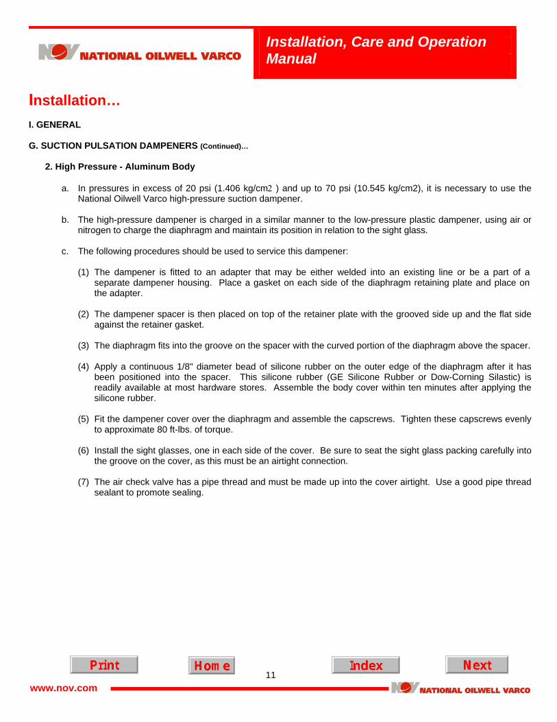
2. High Pressure - Aluminum Body
a. In pressures in excess of 20 psi (1.406 kg/cm2 ) and up to 70 psi (10.545 kg/cm2), it is necessary to use the
National Oilwell Varco high-pressure suction dampener. b. The high-pressure dampener is charged in a similar manner to the low-pressure plastic dampener, using air or
nitrogen to charge the diaphragm and maintain its position in relation to the sight glass. c. The following procedures should be used to service this dampener:
(1) The dampener is fitted to an adapter that may be either welded into an existing line or be a part of a separate dampener housing. Place a gasket on each side of the diaphragm retaining plate and place on the adapter.
(2) The dampener spacer is then placed on top of the retainer plate with the grooved side up and the flat side
against the retainer gasket. (3) The diaphragm fits into the groove on the spacer with the curved portion of the diaphragm above the spacer. (4) Apply a continuous 1/8" diameter bead of silicone rubber on the outer edge of the diaphragm after it has
been positioned into the spacer. This silicone rubber (GE Silicone Rubber or Dow-Corning Silastic) is readily available at most hardware stores. Assemble the body cover within ten minutes after applying the silicone rubber.
(5) Fit the dampener cover over the diaphragm and assemble the capscrews. Tighten these capscrews evenly
to approximate 80 ft-lbs. of torque. (6) Install the sight glasses, one in each side of the cover. Be sure to seat the sight glass packing carefully into
the groove on the cover, as this must be an airtight connection. (7) The air check valve has a pipe thread and must be made up into the cover airtight. Use a good pipe thread
sealant to promote sealing.
12
Installation, Care and Operation Manual
www.nov.com
Lubrication… I. GENERAL
NATIONAL OILWELL VARCO models 101T-4 and 163Q-4 multiplex pumps are "splash" lubricated. The main bearings and crankshaft bearings are fed by splash. Crossheads and crosshead pin bushings are fed through holes in the crossheads and crosshead reservoir. Intermediate rods are lubricated from the splash they receive from the crosshead. NATIONAL OILWELL VARCO models 133T-4 and 217Q-4 multiplex pumps are pressure lubricated via a small gear pump direct driven by the crankshaft. The gear pump provides oil to the crankshaft, connecting rod bearings and crosshead pin bushings. The main bearings and crossheads are splash lubricated from the main oil reservoir and crosshead oil reservoir.
A. OIL
Use "extreme pressure" gear oil. The chart below shows the recommended grades for various temperatures surrounding the pump.
U.S. UNITS OF MEASURE
Temperature AGMA Industrial EP Gear Oil +50°F to +155°F AGMA No. 6 EP or ASTM/ISO Grade No. 320 (viscosity 1335 to 1632 SSU 100°F) +20°F to +100°F AGMA No. 5 EP or ASTM/ISO Grade No. 220 (viscosity 918 to 1122 SSU 100°F) -20°F to + 60°F AGMA No. 2 EP or ASTM/ISO Grade No. 68 (viscosity 284 to 347 SSU 100°F)
Temperature AGMA Industrial Gear Oil +10°C to +68°C AGMA No. 6 EP or ASTM/ISO Grade No. 320 (Viscosity 228-352 cSt at 37.8°C) -7°C to +38°C AGMA No. 5 EP or ASTM/ISO Grade No. 220 (Viscosity 198-242 cSt at 37.8°C)
-29°C to +16°C AGMA No. 2 EP or ASTM/ISO Grade No. 68 (Viscosity 61-75 cSt at 37.8°C) Approximate crankcase Capacity - Liters: 101T-4: 22.7 133T-4: 22.7 (For exact amount observe sight glass provided with pump) 163Q-4: 26.5 217Q-4: 26.5 Oil must pour freely at minimum operating temperature. Change oil every six months or as frequently as operating conditions require maintaining a clean, sludge-free oil of proper viscosity.
13
Installation, Care and Operation Manual
www.nov.com
Operation…
I. GENERAL
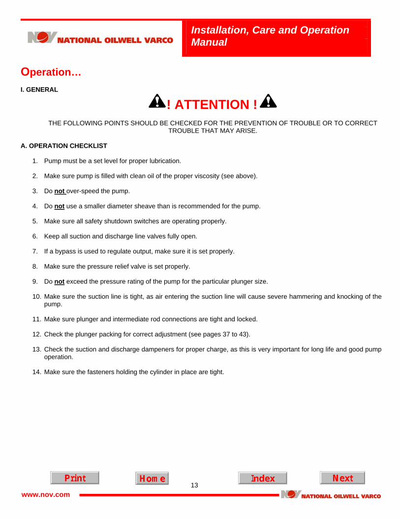
! ATTENTION !
THE FOLLOWING POINTS SHOULD BE CHECKED FOR THE PREVENTION OF TROUBLE OR TO CORRECT TROUBLE THAT MAY ARISE.
A. OPERATION CHECKLIST
1. Pump must be a set level for proper lubrication. 2. Make sure pump is filled with clean oil of the proper viscosity (see above). 3. Do not over-speed the pump.
4. Do not use a smaller diameter sheave than is recommended for the pump.
5. Make sure all safety shutdown switches are operating properly.
6. Keep all suction and discharge line valves fully open.
7. If a bypass is used to regulate output, make sure it is set properly.
8. Make sure the pressure relief valve is set properly.
9. Do not exceed the pressure rating of the pump for the particular plunger size.
10. Make sure the suction line is tight, as air entering the suction line will cause severe hammering and knocking of the
pump.
11. Make sure plunger and intermediate rod connections are tight and locked.
12. Check the plunger packing for correct adjustment (see pages 37 to 43).
13. Check the suction and discharge dampeners for proper charge, as this is very important for long life and good pump operation.
14. Make sure the fasteners holding the cylinder in place are tight.
14
Installation, Care and Operation Manual
www.nov.com
Maintenance… I. GENERAL
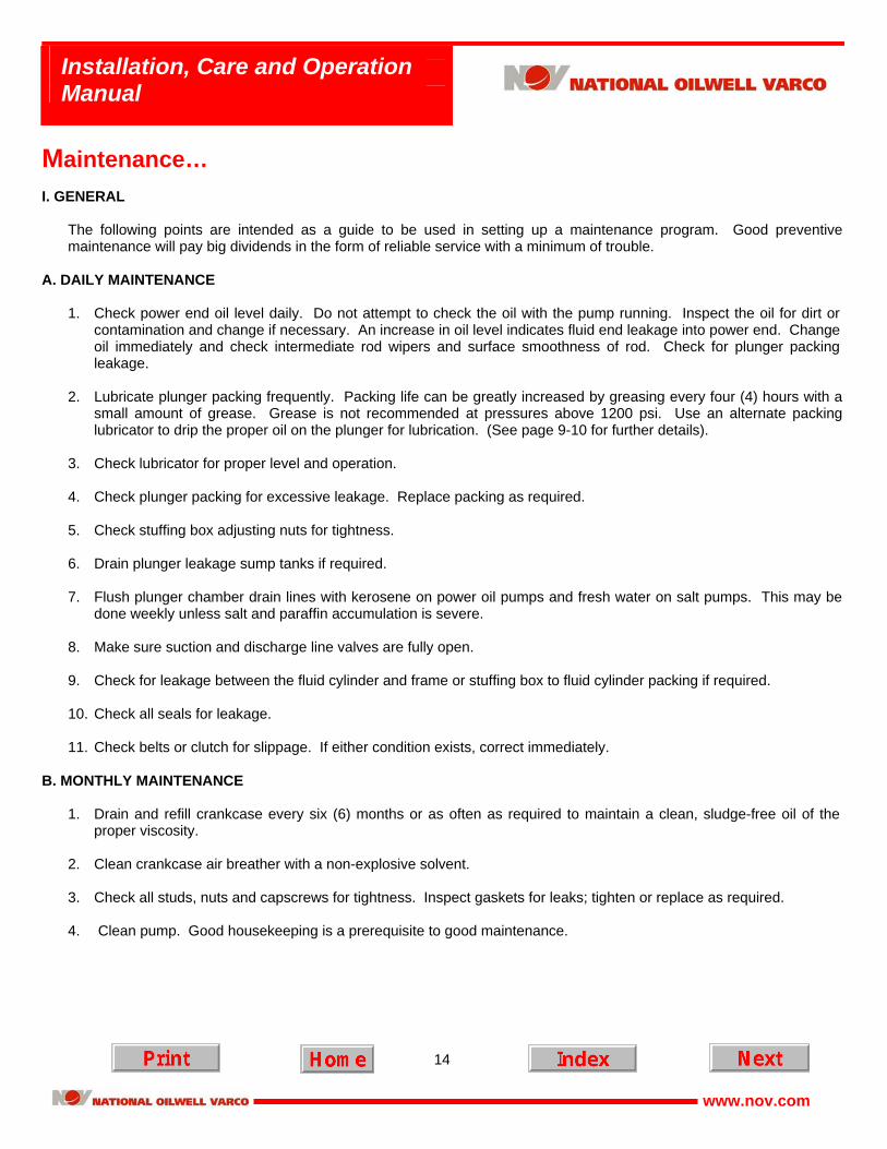
The following points are intended as a guide to be used in setting up a maintenance program. Good preventive maintenance will pay big dividends in the form of reliable service with a minimum of trouble.
A. DAILY MAINTENANCE
1. Check power end oil level daily. Do not attempt to check the oil with the pump running. Inspect the oil for dirt or
contamination and change if necessary. An increase in oil level indicates fluid end leakage into power end. Change oil immediately and check intermediate rod wipers and surface smoothness of rod. Check for plunger packing leakage.
2. Lubricate plunger packing frequently. Packing life can be greatly increased by greasing every four (4) hours with a small amount of grease. Grease is not recommended at pressures above 1200 psi. Use an alternate packing lubricator to drip the proper oil on the plunger for lubrication. (See page 9-10 for further details).
3. Check lubricator for proper level and operation. 4. Check plunger packing for excessive leakage. Replace packing as required. 5. Check stuffing box adjusting nuts for tightness. 6. Drain plunger leakage sump tanks if required. 7. Flush plunger chamber drain lines with kerosene on power oil pumps and fresh water on salt pumps. This may be
done weekly unless salt and paraffin accumulation is severe. 8. Make sure suction and discharge line valves are fully open. 9. Check for leakage between the fluid cylinder and frame or stuffing box to fluid cylinder packing if required. 10. Check all seals for leakage. 11. Check belts or clutch for slippage. If either condition exists, correct immediately.
B. MONTHLY MAINTENANCE
1. Drain and refill crankcase every six (6) months or as often as required to maintain a clean, sludge-free oil of the proper viscosity.
2. Clean crankcase air breather with a non-explosive solvent. 3. Check all studs, nuts and capscrews for tightness. Inspect gaskets for leaks; tighten or replace as required. 4. Clean pump. Good housekeeping is a prerequisite to good maintenance.
15
Installation, Care and Operation Manual
www.nov.com
Maintenance… I. GENERAL (Continued)… C. STORAGE
If the pump is to be idle for longer than one (1) week, it should be prepared for storage as follows:
1. Drain and clean crankcase thoroughly. Leave drain open and install 90° elbow, pointing downward, to permit air circulation and prevent condensation build-up.
2. Coat all bearings, finished surfaces, and entire inside surface of crankcase with a rust inhibiting oil. 3. Remove plungers and packing, clean and coat with rust inhibiting oil. 4. Remove fluid cylinder valves allowing cylinder to be thoroughly cleaned and drained. 5. Coat entire cylinder, valves and parts, with a rust inhibiting oil. 6. Thoroughly inspect pump and rotate crankcase once each month. Re-coat with rust inhibiting oil where necessary.
D. START-UP AFTER STORAGE
Any pump that has been in storage, either after field use or as shipped from the plant, will need a thorough inspection to make sure it has not been damaged in any way and that all parts are properly in place.
! ATTENTION !
FAILURE TO OBSERVE THE FOLLOWING POINTS CAN RESULT IN SERIOUS DAMAGE.
1. Remove all covers on both power end and fluid end; thoroughly clean and inspect all parts and finished surfaces. 2. Check all bearings to make sure they are clean and in good condition. 3. Make sure valves, plungers and packing are properly installed and in good condition. 4. Carefully tighten all bolts, nuts, studs and working connections. 5. Fill power end to the proper level with clean oil of the proper viscosity. Make sure oil is poured into the crosshead
reservoir and is worked into all bearings. 6. Fill packing lubricator and pump lines full. Check by breaking connection at stuffing box, working lubricator plunger
until oil appears.
16
Installation, Care and Operation Manual
www.nov.com
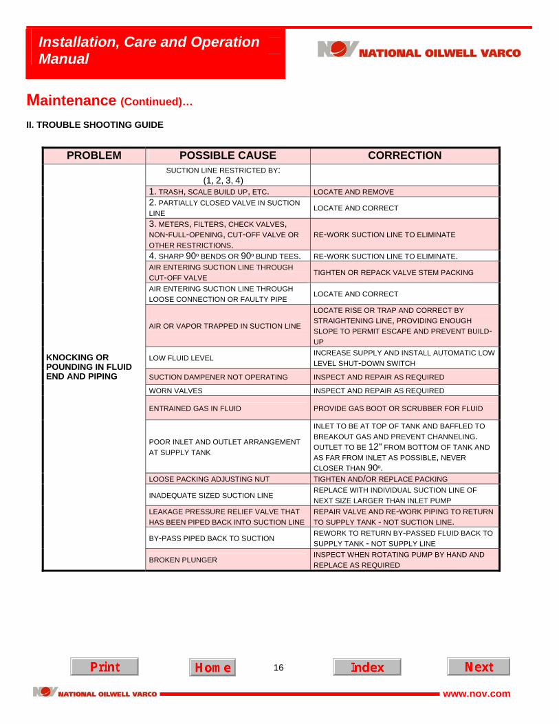
Maintenance (Continued)… II. TROUBLE SHOOTING GUIDE
PROBLEM POSSIBLE CAUSE CORRECTION
SUCTION LINE RESTRICTED BY: (1, 2, 3, 4)
1. TRASH, SCALE BUILD UP, ETC. LOCATE AND REMOVE 2. PARTIALLY CLOSED VALVE IN SUCTION LINE LOCATE AND CORRECT
3. METERS, FILTERS, CHECK VALVES, NON-FULL-OPENING, CUT-OFF VALVE OR OTHER RESTRICTIONS.
RE-WORK SUCTION LINE TO ELIMINATE
4. SHARP 90º BENDS OR 90º BLIND TEES. RE-WORK SUCTION LINE TO ELIMINATE. AIR ENTERING SUCTION LINE THROUGH CUT-OFF VALVE TIGHTEN OR REPACK VALVE STEM PACKING
AIR ENTERING SUCTION LINE THROUGH LOOSE CONNECTION OR FAULTY PIPE LOCATE AND CORRECT
AIR OR VAPOR TRAPPED IN SUCTION LINE
LOCATE RISE OR TRAP AND CORRECT BY STRAIGHTENING LINE, PROVIDING ENOUGH SLOPE TO PERMIT ESCAPE AND PREVENT BUILD-UP
SUCTION DAMPENER NOT OPERATING INSPECT AND REPAIR AS REQUIRED WORN VALVES INSPECT AND REPAIR AS REQUIRED
ENTRAINED GAS IN FLUID PROVIDE GAS BOOT OR SCRUBBER FOR FLUID
POOR INLET AND OUTLET ARRANGEMENT AT SUPPLY TANK
INLET TO BE AT TOP OF TANK AND BAFFLED TO BREAKOUT GAS AND PREVENT CHANNELING. OUTLET TO BE 12" FROM BOTTOM OF TANK AND AS FAR FROM INLET AS POSSIBLE, NEVER CLOSER THAN 90º.
INADEQUATE SIZED SUCTION LINE REPLACE WITH INDIVIDUAL SUCTION LINE OF NEXT SIZE LARGER THAN INLET PUMP
LEAKAGE PRESSURE RELIEF VALVE THAT HAS BEEN PIPED BACK INTO SUCTION LINE
REPAIR VALVE AND RE-WORK PIPING TO RETURN TO SUPPLY TANK - NOT SUCTION LINE.
BY-PASS PIPED BACK TO SUCTION REWORK TO RETURN BY-PASSED FLUID BACK TO SUPPLY TANK - NOT SUPPLY LINE
KNOCKING OR POUNDING IN FLUID END AND PIPING
BROKEN PLUNGER INSPECT WHEN ROTATING PUMP BY HAND AND REPLACE AS REQUIRED
17
Installation, Care and Operation Manual
www.nov.com
Maintenance… II. TROUBLE SHOOTING GUIDE (Continued)…
PROBLEM POSSIBLE CAUSE CORRECTION
VALVE WEAR OR DAMAGE CHECK FLUID END FOR BAD VALVES WORN MAIN BEARINGS REPLACE AS REQUIRED
LOOSE PLUNGER - INTERMEDIATE ROD CROSSHEAD CONNECTION
INSPECT FOR DAMAGE - REPLACE AS REQUIRED AND TIGHTEN
KNOCK IN POWER END
WORN CROSSHEAD PIN, OR CONNECTING ROD LOCATE AND REPLACE AS REQUIRED
CORROSION TREAT FLUID AS REQUIRED
ABRASIVES IN FLUID FILTER AS REQUIRED
IMPROPER INSTALLATION INSPECT AND INSTALL PER INSTRUCTION SHEET IN PACKING BOX
IMPROPER LUBRICATION (EITHER INSUFFICIENT OR EXCESSIVE OR INCORRECT TYPE)
CHECK INSTRUCTIONS IN MANUAL AND CORRECT AS REQUIRED.
LUBRICATOR NOT OPERATING INSPECT AND CORRECT AS REQUIRED
ADJUSTING NUT LOOSE INSPECT AND REPACK PER INSTRUCTIONS
RAPID VALVE WEAR OR FAILURE
SCALE OR BUILD UP ON PLUNGER TREAT FLUID AS REQUIRED WORN OR PITTED PLUNGERS AND/OR STUFFING BOX REPLACE AS REQUIRED
ABRASIVES IN FLUID FILTER AS REQUIRED
PUMP OPERATED WITHOUT FLUID CHECK SYSTEM FOR FAULTY LOW-LEVEL SHUTDOWN CONTROLS OR CLOSED VALVES AND CORRECT AS REQUIRED.
ABNORMALLY HIGH FLUID TEMPERATURES
CHECK WITH MANUFACTURER FOR RECOMMENDATIONS ON TYPE OF PACKING
WRONG TYPE OF PACKING FOR PARTICULAR FLUID BEING HANDLED
CHECK WITH MANUFACTURER FOR RECOMMENDATIONS ON TYPE OF PACKING
SHORT PACKING LIFE
CAVITATION (KNOCKING AND POUNDING IN FLUID CYLINDER AND PIPING)
REFER TO CORRECTION OF "KNOCK IN POWER END" ABOVE
18
Installation, Care and Operation Manual
www.nov.com
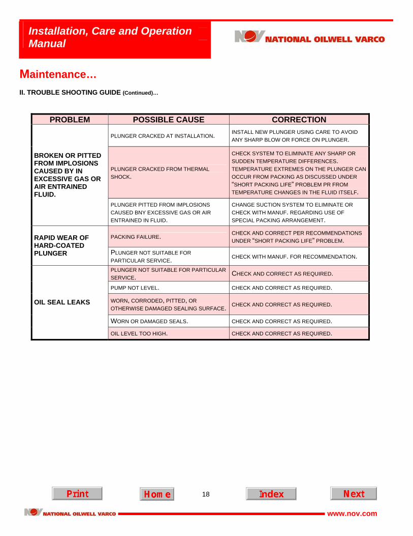
Maintenance… II. TROUBLE SHOOTING GUIDE (Continued)…
PROBLEM POSSIBLE CAUSE CORRECTION
PLUNGER CRACKED AT INSTALLATION. INSTALL NEW PLUNGER USING CARE TO AVOID ANY SHARP BLOW OR FORCE ON PLUNGER.
PLUNGER CRACKED FROM THERMAL SHOCK.
CHECK SYSTEM TO ELIMINATE ANY SHARP OR SUDDEN TEMPERATURE DIFFERENCES. TEMPERATURE EXTREMES ON THE PLUNGER CAN OCCUR FROM PACKING AS DISCUSSED UNDER “SHORT PACKING LIFE” PROBLEM PR FROM TEMPERATURE CHANGES IN THE FLUID ITSELF.
BROKEN OR PITTED FROM IMPLOSIONS CAUSED BY IN EXCESSIVE GAS OR AIR ENTRAINED FLUID.
PLUNGER PITTED FROM IMPLOSIONS CAUSED BNY EXCESSIVE GAS OR AIR ENTRAINED IN FLUID.
CHANGE SUCTION SYSTEM TO ELIMINATE OR CHECK WITH MANUF. REGARDING USE OF SPECIAL PACKING ARRANGEMENT.
PACKING FAILURE. CHECK AND CORRECT PER RECOMMENDATIONS UNDER “SHORT PACKING LIFE” PROBLEM. RAPID WEAR OF
HARD-COATED PLUNGER PLUNGER NOT SUITABLE FOR
PARTICULAR SERVICE. CHECK WITH MANUF. FOR RECOMMENDATION.
PLUNGER NOT SUITABLE FOR PARTICULAR SERVICE. CHECK AND CORRECT AS REQUIRED.
PUMP NOT LEVEL. CHECK AND CORRECT AS REQUIRED.
WORN, CORRODED, PITTED, OR OTHERWISE DAMAGED SEALING SURFACE. CHECK AND CORRECT AS REQUIRED.
WORN OR DAMAGED SEALS. CHECK AND CORRECT AS REQUIRED.
OIL SEAL LEAKS
OIL LEVEL TOO HIGH. CHECK AND CORRECT AS REQUIRED.
19
Installation, Care and Operation Manual
www.nov.com
Overhaul and Repair… I. GENERAL
The bearings and other working parts in the power end have been designed for continuous duty, and if properly lubricated, will provide years of trouble-free service. However, after the pump has been in service for a long period of time, the bearings and other working parts will gradually loosen, and if not corrected, will lead to more serious trouble. The time to overhaul the pump will vary; depending on the operating conditions, and is therefore a matter that must be left to the good judgment of the operator. Complete disassembly and assembly procedures are discussed in their respective sections.
A. TOOLS REQUIRED
Most of the tools required to overhaul the pump will be found in an ordinary set of mechanics hand tools. The special tools and equipment required and not furnished with the pump include a torque wrench, bearing puller, and a valve servicing kit. Also, a hot oil bath capable of reaching a temperature of 300°F (149°C) will be needed.
B. CHECK POINTS AND ADJUSTMENTS
1. 101T-4 and 133T-4:
The crankshaft main bearings are single row, shim adjusted, tapered roller bearings. They have been assembled and adjusted at the factory with proper clearance and will give long trouble-free service. The proper clearance is found by adjusting the amount of shims until the crankshaft has 0.003" to 0.005" (0.076 mm to 0.127 mm) endplay and will rotate freely.
2. 163Q-4 and 217Q-4:
The 163Q-4 and 217Q-4 have two single rows, shim adjusted, tapered roller end bearings. They have been assembled and adjusted at the factory with proper clearance and will give long trouble-free service. The proper end clearance is found by adjusting the amount of shims until the crankshaft has 0.005" to 0.007" (0.127 mm to 0.178 mm) end play and will rotate freely. These pumps also have two steel backed Babbitt center mains which are non adjustable. The center mains should have 0.010” to .016” (0.254 mm to 0.406 mm) total diametrical clearance or 0.005” (0.127mm) to 0.008” (0.203 mm) per side clearance. This is non adjustable.
3. 101T-4, 133T-4, 163Q-4 and 217Q-4:
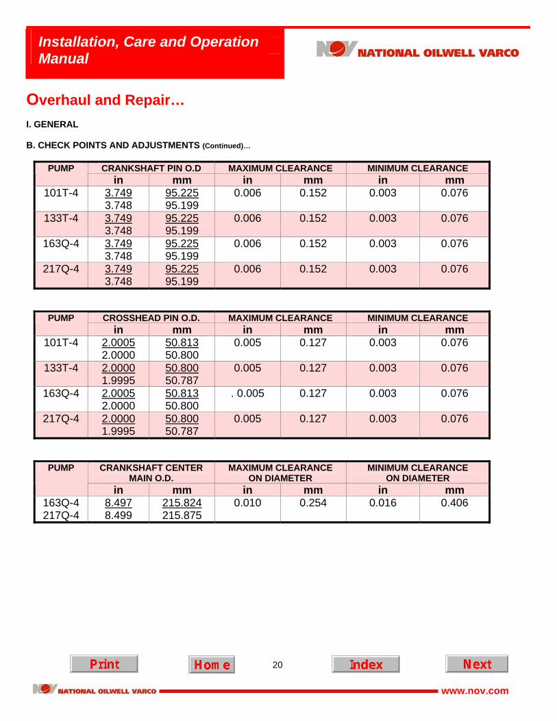
a. The connecting rod shell bearings or inserts are precision made tri-metal bearing. These bearings do not have shims and are not adjustable. The running clearance for the shell bearings is 0.003” (0.076 mm) to 0.006” (0.152 mm).
b. The normal clearance between the crosshead and crosshead bore is 0.005” (0.127 mm) to 0.012” (0.305 mm).
The maximum allowable clearance, including wear, is 0.017” (0.432 mm). c. The wrist pin bushings must be pressed into the connecting rods and reamed to size. The allowable clearance
between the pin and bushing is listed on the following page.
20
Installation, Care and Operation Manual
www.nov.com
Overhaul and Repair… I. GENERAL B. CHECK POINTS AND ADJUSTMENTS (Continued)…
CRANKSHAFT PIN O.D MAXIMUM CLEARANCE MINIMUM CLEARANCE PUMP in mm in mm in mm
101T-4 3.749 3.748
95.225 95.199
0.006 0.152 0.003 0.076
133T-4
3.749 3.748
95.225 95.199
0.006 0.152 0.003 0.076
163Q-4 3.749 3.748
95.225 95.199
0.006 0.152 0.003 0.076
217Q-4
3.749 3.748
95.225 95.199
0.006 0.152 0.003 0.076
CROSSHEAD PIN O.D. MAXIMUM CLEARANCE MINIMUM CLEARANCE PUMP in mm in mm in mm
101T-4 2.0005 2.0000
50.813 50.800
0.005 0.127 0.003 0.076
133T-4
2.0000 1.9995
50.800 50.787
0.005 0.127 0.003 0.076
163Q-4 2.0005 2.0000
50.813 50.800
. 0.005 0.127 0.003 0.076
217Q-4
2.0000 1.9995
50.800 50.787
0.005 0.127 0.003 0.076
CRANKSHAFT CENTER MAIN O.D.
MAXIMUM CLEARANCE ON DIAMETER
MINIMUM CLEARANCE ON DIAMETER
PUMP
in mm in mm in mm 163Q-4 217Q-4
8.497 8.499
215.824 215.875
0.010 0.254 0.016 0.406
21
Installation, Care and Operation Manual
www.nov.com
Disassembly… I. POWER END
It is not necessary to remove the fluid end when disassembling the power end. However, the plungers and (if applicable) intermediate rods should be removed through the fluid end cylinder heads.
! ATTENTION !
POWER END DISASSEMBLY AND OVERHAUL IS BEST PERFORMED IN A WELL EQUIPED SHOP ENVIROMENT. IF THE PUMP IS DISASSEMBLED AT LOCATION ENSURE THE PRESSURE HAS BEEN REMOVED FROM THE FLUID END AND
THE PUMP BLOCKED OUT WITH APPROPRIATE BLOCK VALVES. ENSURE THE FLUID END IS DRAINED AND ANY POWER SOURCE OR DRIVER IS LOCKED OUT BEFORE PROCEEDING!
A. PLUNGER/INTERMEDIATE RODS AND OIL WIPER RETAINERS (ALL PUMPS)
1. Remove the fluid end cylinder head. 2. Loosen the packing gland nuts. 3. If the pump has intermediate rods a back-up wrench is required. The plunger and intermediate rod separate at the
knurl area interface. Using the back-up wrench break the plunger loose and unscrew from the intermediate rod. Remove the plunger through the fluid cylinder opening.
4. Using a pipe wrench on the knurled area of the intermediate rod, remove it from the crosshead and power end.
5. If the pump does not have an intermediate rod, use a pipe wrench on the knurled area of the plunger and break it
loose from the crosshead. Unscrew and remove through the fluid cylinder opening.
6. Remove the two nuts holding the wiper box gland and remove the gland.
7. Slide the wiper box and seal assembly out of the power end. B. CRANKSHAFT ASSEMBLY • 101T-4 & 133T-4
1. Remove the rear power end crankcase cover. 2. Remove connecting rod bolts and cap.
NOTE: Connecting rods and caps are matched marked and must be kept together. Do not mix caps and rods.
3. Connecting rod and crosshead must be moved all the way forward to clear crankshaft. 4. Remove crankshaft bearing retainers, seals, and shims. These parts should be tied together and marked for
reassembly at their original location. Thread bearing retainer capscrews into the two tapped holes of each bearing retainer and use them to push the bearing retainers out of their bores.
22
Installation, Care and Operation Manual
www.nov.com
Disassembly… I. POWER END B. CRANKSHAFT ASSEMBLY • 101T-4 & 133T-4 (Continued)…
! ATTENTION !
COVER KEYWAYS TO PROTECT OIL SEALS DURING REMOVAL.
5. Carefully remove the crankshaft out either side of the power frame. If reusing the end bearings remember, the crankshaft end bearing cones and cups are matched sets. Do not mix cones and cups.
• 163Q-4 & 217Q-4
1. Remove the rear power end crankcase cover. 2. Remove connecting rod bolts and cap.
NOTE: Connecting rods and caps are matched marked and must be kept together. Do not mix caps and rods.
3. Connecting rod and crosshead must be moved all the way forward to clear crankshaft. 4. Remove crankshaft bearing retainers, seals, and shims. These parts should be tied together and marked for
reassembly at their original location. Thread bearing retainer capscrews into the two tapped holes of each bearing retainer and use them to push the bearing retainers out of their bores.
5. While supporting the crankshaft carefully remove it out either side of the power frame. If reusing the end bearings
remember, the crankshaft end bearing cones and cups are matched sets. Do not mix cones and cups.
C. CRANKSHAFT BEARINGS • 101T-4, 133T-4, 163Q-4 & 217Q-4
The crankshaft main bearings may be inspected while on the crankshaft and should not be removed unless necessary. A puller is required when replacement is necessary.
NOTE: Keep the component parts of the bearings together if they are to be re-installed. They are match sets and must
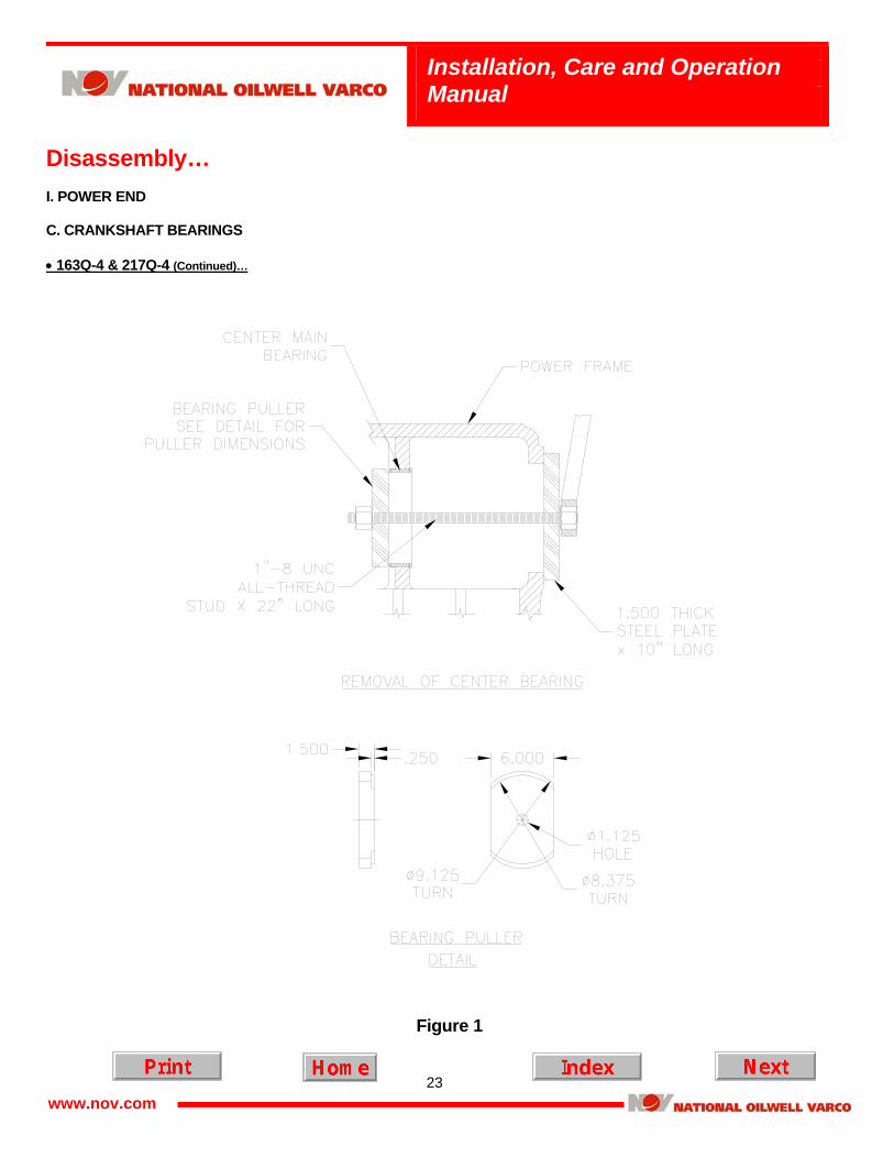
be correctly assembled as a unit. • 163Q-4 & 217Q-4 The center main bearings on the quintuplex model pumps normally have from 0.010” to 0.016” inches total diametrical
clearance (0.005” to 0.008” per side). When they require replacement a puller is necessary to remove them. Figure 1 shows a puller that can be made to remove old bearings and install new ones.
23
Installation, Care and Operation Manual
www.nov.com
Disassembly… I. POWER END C. CRANKSHAFT BEARINGS • 163Q-4 & 217Q-4 (Continued)…
Figure 1
24
Installation, Care and Operation Manual
www.nov.com
Disassembly… I. POWER END (Continued)… D. LUBRICATION OIL PUMP • 133T-4 & 217Q-4
The model 133T-4 and 217Q-4 have a lubrication pump that is an integral part of the power frame assembly. It is driven by a slotted shaft which is driven via the crankshaft. It has its own strainer/filter, oil pressure gauge, and relief valve. The pump draws oil through the strainer/filter located in the crankcase reservoir and discharges into the crankshaft, where it lubricates all connecting rod and wrist pin bearings. See figure 2.
Figure 2 The lube oil pump may be removed by removing the 8 capscrews retaining the oil pump to the lube side bearing housing.
After removing the capscrews, the complete unit may be slipped out. It is not necessary to disturb either the crankshaft or bearing housing.
The relief valve, located on top of the housing is adjustable and prevents excessive lube pressure during cold starts. It is
adjusted at the factory for normal operating conditions. However, since operating conditions do vary, it may be necessary to adjust after installation. Crankshaft speed, type of oil and oil temperature directly affect the oil operating pressure. To adjust the oil pressure, operate pump until normal operating temperature is reached. Remove the cap and loosen the jam nut. Turn the adjusting screw in or out until the desired pressure is reached. Retighten the jam nut and replace the cap. Under normal speeds and temperatures the oil pressure should be adjusted somewhere between 30 and 40 psi. However, because of the variable factors affecting the oil pressure the pump has been designed to operate safely from 15 psi or more.
25
Installation, Care and Operation Manual
www.nov.com
Disassembly… I. POWER END D. LUBRICATION OIL PUMP (Continued)…
Sometimes the drive side of the pump must be reversed. When swapping the drive from right hand to left hand or opposite, care must be taken to correctly swap the lube side bearing housing and oil pump. The power frame is machined to be driven from either the right or left side. In order to do this, the power frame is machined symmetrically. This means the port for the oil suction must be plugged on the drive side to prevent oil leakage. When swapping drives, this plug must also change sides. See figure 3 for details of the plug and strainer/filter changes.
Figure 3 When changing drive side, the lube side bearing housing, oil pump, oil strainer/filter and components from the lube side are
swapped to the drive side. The pipe plug, port plug, and O-ring from the drive side are switch to the opposite side. If the port plug is not removed it will block the oil suction port and the pump will starve for oil when started. If the port plug is not installed on the opposite side, oil will leak from under the bearing housing.
26
Installation, Care and Operation Manual
www.nov.com
Disassembly… I. POWER END (Continued)… E. INTEGRAL GEAR REDUCER
The 101T-4, 133T-4, 163Q-4 and 217Q-4 may be purchased with an optional integral gear reducer. Because of the gear design these are available in left hand drive only.
1. Drain oil from pump and gear reducer. 2. Remove the 1/2” capscrews around the outside of the gear case cover.
3. Using a support carefully remove the cover.
4. Remove the pinion shaft.
5. If you have a 101T-4 or 133T-4, remove the bolt and nut clamping the bull gear to the crankshaft. If you have a 163Q-4
or 217Q-4, remove the 8 bolts holding the gear to the hub.
6. Use a puller and sling to carefully remove the bull gear.
7. Remove the 5/8” fasteners holding the gear case to the power frame.
8. Using a sling and jib crane, carefully remove the gear case. II. FLUID END
! ATTENTION !
BEFORE WORKING ON THE FLUID END ENSURE THE PRESSURE HAS BEEN REMOVED FROM THE FLUID END AND THE PUMP BLOCKED OUT WITH APPROPRIATE BLOCK VALVES. ENSURE THE FLUID END IS DRAINED AND ANY
POWER SOURCE OR DRIVER IS LOCKED OUT BEFORE PROCEEDING! A. FLUID CYLINDER REMOVAL • ALL PUMPS
1. Disconnect piping. 2. Remove the plungers as described below. 3. Remove the hex nuts holding the fluid end to the power end and slide cylinder forward until free.
27
Installation, Care and Operation Manual
www.nov.com
Disassembly (Continued)… II. FLUID END B. PLUNGER REMOVAL
1. Remove the fluid end cylinder head. 2. Loosen the packing gland nuts.
3. Rotate the crankshaft until the knurl area of the plunger/intermediate rod is accessible in the cradle area of the
pump. 4. If the pump has intermediate rods a back-up wrench is required. The plunger and intermediate rod separate at the
knurl area interface. Using the back-up wrench break the plunger loose and unscrew from the intermediate rod. Remove the plunger through the fluid cylinder opening.
5. If replacing the intermediate rod, use a pipe wrench on the knurled area of the intermediate rod and remove it from
the crosshead and power end.
6. If the pump does not have an intermediate rod, use a pipe wrench on the knurled area of the plunger and break it loose from the crosshead. Unscrew and remove through the fluid cylinder opening.
C. STUFFING BOXES REMOVAL • ALL PUMPS
Most pumps in this series have integral stuffing boxes. A few models do have separate stuffing boxes. On these pumps the stuffing box is clamped between the fluid end body and the power frame. The fit on the fluid end side is a slip fit. The fit on the power end side is a slight press. To remove the stuffing boxes follow this procedure.
1. Remove the plungers and fluid end as previously described. 2. Remove any lube fittings, etc. 3. Support the box with a lifting strap 4. Use a heavy brass bar and drive the box out of the power frame opening.
D. FLUID END VALVE REMOVAL Refer to valve section of this manual.
28
Installation, Care and Operation Manual
www.nov.com
Assembly…
I. POWER END A. CONNECTING ROD AND CROSSHEAD ASSEMBLY • 101T-4 and 163Q-4
1. Press the crosshead pin bushing into the connecting rod. 2. Ream bushing to obtain the clearance listed on page 20. (If service bushings are used, reaming will not be necessary in
most cases). 3. Assembly the connecting rod to the crosshead by pressing the crosshead pin into the crosshead or to facilitate
assembly, the crosshead may be heated to no more than 300°F (149°C) in an electric oven or bath.
NOTE: Crossheads have an oil groove on the topside. Connecting rods and bearing caps are match marked as units. The rod also has a lube hole on the topside. Install connecting rod in crosshead so the lube hole on the rod and the oil groove on the crosshead correspond. The oil groove and lube hole go up when installing in the power frame. See figure 4.
4. Lubricate the crosshead bore and slide the connecting rod crosshead assembly into the power frame. Push the
assemblies all the way forward.
Figure 4
29
Installation, Care and Operation Manual
www.nov.com
Assembly… I. POWER END A. CONNECTING ROD AND CROSSHEAD ASSEMBLY (Continued)… • 133T-4 and 217Q-4
1. Press the crosshead pin bushing into the connecting rod. 2. Ream bushing to obtain the clearance listed on page 20. (If service bushings are used, reaming will not be necessary in
most cases). 3. Assembly the connecting rod to the crosshead by pressing the crosshead pin into the crosshead or to facilitate
assembly, the crosshead may be heated to no more than 300° F (149°C) in an electric oven or bath. Install the two snap rings into the grooves in the crosshead.
NOTE: Crossheads have an oil groove on the topside. Connecting rods and bearing caps are match marked as units. The rod also has a lube hole drilled through the main beam of the rod to allow pressurized oil to reach the wrist pin bearing. Ensure this hole is free of dirt and trash. The oil groove on the crossheads go up when installing in the power frame. See figure 5.
4. Lubricate the crosshead bore and slide the connecting rod crosshead assembly into the power frame. Push the
assemblies all the way forward.
Figure 5
30
Installation, Care and Operation Manual
www.nov.com
Assembly… I. POWER END (Continued)… B. CRANKSHAFT AND MAIN BEARINGS • 101T-4 and 133T-4
1. Thoroughly clean and remove all burrs from the I.D. of the cone and roller assembly and from the bearing seating surfaces on the crankshaft.
2. Heat the cone and roller assembly in an electric oven or oil bath to 300°F (149°C). It is recommended that a
thermometer be used to prevent overheating. 3. After the bearings have been brought up to temperature and with the crankshaft firmly supported, install the cone and
roller assemblies on the crankshaft. Make sure the cone and roller assemblies are firmly against the shoulders on the crankshaft.
4. Allow the crankshaft and bearing assembly to cool before installing in the power end. 5. Make sure the main bearing openings in the frame are clean and free of burrs.
NOTE: The crossheads and connecting rods must be installed prior to replacing the crankshaft assembly. 6. Install the crankshaft main bearing outer races or cups in the main bearing housing. These races can be carefully driven
into the housing with a brass rod. An alternative and easier way is to chill the races in a freezer or with CO2 and place them in their respective bearing housings. Ensure the races are completely seated.
7. For the 101T-4 place the crankcase main bearing shims, amounting to approximately 0.120" (3.048 mm) in thickness, on
the crankshaft-bearing housing/retainers. If the old bearings and retainers are being re-installed, use the same amount of shims as before.
8. For the 133T-4 place the crankcase main bearing shims, amounting to approximately 0.170" (4.318 mm) in thickness, on
the crankshaft-bearing housing/retainers. If the old bearings and retainers are being re-installed, use the same amount of shims as before.
9. Install the off drive side bearing housing with shims in the power frame and tighten in place with the proper capscrews. 10. With the cone and roller assemblies of the main bearings in place on the crankshaft, slide the crankshaft through the
main bearing openings in the power end frame with No. 1 throw forward. Slide the off drive side bearing into its bearing housing and race.
11. Assemble the drive side crankshaft-bearing housing/retainer and shims to the main frame and tighten in place with the
proper capscrews. NOTE: The following steps (12a and 12b) are necessary only if new bearings are being installed. When the same
crankshaft main bearings are being reassembled, use the same amount of shims as were previously used and use the steps as a check for adjustment.
12. To determine the correct amount of shims when installing new bearings, the following steps are recommended.
31
Installation, Care and Operation Manual
www.nov.com
Assembly I. POWER END B. CRANKSHAFT AND MAIN BEARINGS • 101T-4 and 133T-4 (Continued)…
a. When first installing shims, use only enough shims to produce a slight drag when the crankshaft is rotated. Tap shaft on each end sufficient to ensure that the bearing outer race is tightly against the retainer.
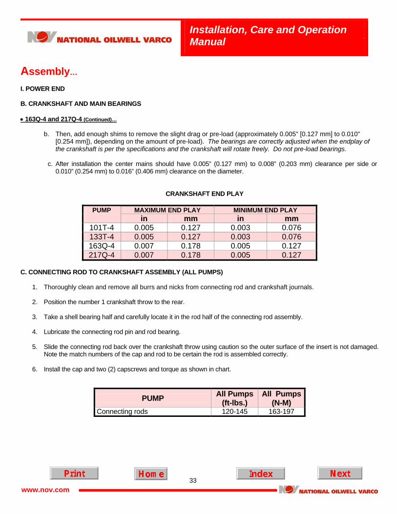
b. Then, add enough shims to remove the slight drag or pre-load (approximately 0.005" [0.127 mm] to 0.010"
[0.254 mm]), depending on the amount of pre-load). The bearings are correctly adjusted when the endplay of the crankshaft is per the specifications and the crankshaft will rotate freely. Do not pre-load bearings.
CRANKSHAFT END PLAY
MAXIMUM END PLAY MINIMUM END PLAY PUMP
in mm in mm 101T-4 0.005 0.127 0.003 0.076 133T-4 0.005 0.127 0.003 0.076 163Q-4 0.007 0.178 0.005 0.127 217Q-4 0.007 0.178 0.005 0.127
• 163Q-4 and 217Q-4
1. Thoroughly clean and remove all burrs from the I.D. of the cone and roller assembly and from the bearing seating surfaces on the crankshaft.
2. Heat the cone and roller assembly in an electric oven or oil bath to 300°F (149°C). It is recommended that a
thermometer be used to prevent overheating. 3. After the bearings have been brought up to temperature and with the crankshaft firmly supported, install the cone and
roller assemblies on the crankshaft. Make sure the cone and roller assemblies are firmly against the shoulders on the crankshaft.
4. Allow the crankshaft and bearing assembly to cool before installing in the power end. 5. If installing new steel backed Babbitt lined center mains, install them at this time as described below.
a. Chill the bearings in a freezer or with CO2.
b. Position the “half moon” cut outs in the bearings toward the front of the power frame. These are necessary for the
crosshead to clear the bearing when at bottom dead center.
32
Installation, Care and Operation Manual
www.nov.com
Assembly… I. POWER END B. CRANKSHAFT AND MAIN BEARINGS • 163Q-4 & 217Q-4 (Continued)…
c. Carefully install the center mains. With chilled center mains the bearings will slip into the bore or take a slight tap with a brass rod. Do not “beat” the bearings into place as this will damage them.
d. Allow the center mains to warm before proceeding. e. If you do not have a method to chill the bearings, they can be pulled into place with a bearing installation tool. See
figure 1 in the power end disassembly section for a typical bearing puller/installation tool. When using this method take care to not damage the bearing surface and remove any slight raised spots or burrs that occur from installing before proceeding.
6. Make sure the main bearing openings in the frame are clean and free of burrs.
NOTE: The crossheads and connecting rods must be installed prior to replacing the crankshaft assembly. 7. Install the crankshaft main bearing outer races or cups in the main bearing housing. These races can be carefully driven
into the housing with a brass rod. An alternative and easier way is to chill the races in a freezer or with CO2 and place them in their respective bearing housings. Ensure the races are completely seated.
8. For the 163Q-4 place the crankcase main bearing shims, amounting to approximately 0.120" (3.048 mm) in thickness,
on the crankshaft-bearing housing/retainers. If the old bearings and retainers are being re-installed, use the same amount of shims as before.
9. For the 217Q-4 place the crankcase main bearing shims, amounting to approximately 0.135” (3.429 mm) in thickness,
on the crankshaft-bearing housing/retainers. If the old bearings and retainers are being re-installed, use the same amount of shims as before.
10. Install the off drive side bearing housing with shims in the power frame and tighten in place with the proper capscrews. 11. With the cone and roller assemblies of the main bearings in place on the crankshaft, carefully slide the crankshaft
through the main bearing openings in the power end frame with No. 1 throw forward. Slide the off drive side bearing into its bearing housing and race.
12. Assemble the drive side crankshaft-bearing housing/retainer and shims to the main frame and tighten in place with the
proper capscrews. NOTE: The following steps (13a and 13b) are necessary only if new bearings are being installed. When the same
crankshaft main bearings are being reassembled, use the same amount of shims as were previously used and use the steps as a check for adjustment.
13. To determine the correct amount of shims when installing new bearings, the following steps are recommended.
a. When first installing shims, use only enough shims to produce a slight drag when the crankshaft is rotated. Tap
shaft on each end sufficient to ensure that the bearing outer race is tightly against the retainer.
33
Installation, Care and Operation Manual
www.nov.com
Assembly… I. POWER END B. CRANKSHAFT AND MAIN BEARINGS • 163Q-4 and 217Q-4 (Continued)…
b. Then, add enough shims to remove the slight drag or pre-load (approximately 0.005" [0.127 mm] to 0.010"
[0.254 mm]), depending on the amount of pre-load). The bearings are correctly adjusted when the endplay of the crankshaft is per the specifications and the crankshaft will rotate freely. Do not pre-load bearings.
c. After installation the center mains should have 0.005” (0.127 mm) to 0.008” (0.203 mm) clearance per side or
0.010” (0.254 mm) to 0.016” (0.406 mm) clearance on the diameter.
CRANKSHAFT END PLAY
MAXIMUM END PLAY MINIMUM END PLAY PUMP in mm in mm
C. CONNECTING ROD TO CRANKSHAFT ASSEMBLY (ALL PUMPS)
1. Thoroughly clean and remove all burrs and nicks from connecting rod and crankshaft journals. 2. Position the number 1 crankshaft throw to the rear. 3. Take a shell bearing half and carefully locate it in the rod half of the connecting rod assembly. 4. Lubricate the connecting rod pin and rod bearing. 5. Slide the connecting rod back over the crankshaft throw using caution so the outer surface of the insert is not damaged.
Note the match numbers of the cap and rod to be certain the rod is assembled correctly. 6. Install the cap and two (2) capscrews and torque as shown in chart.
PUMP All Pumps (ft-lbs.)
All Pumps (N-M)
Connecting rods 120-145 163-197
34
Installation, Care and Operation Manual
www.nov.com
Assembly (Continued)… D. INTERMEDIATE RODS AND OIL SEAL RETAINERS • ALL PUMPS The power end wiper box is held in the power frame by two adjustment studs and the wiper box gland. After removing the plunger/adapter rod and wiper box gland the stuffing box may be pushed out of the power end. The standard wiper box seals are molded lip seals. To replace the seals follow the instructions below.
1. Clean the stuffing box and gland.
2. Lubricate a new set of seals and install in the stuffing box while taking care to not damage the lips.
3. Place the stuffing box back in the power frame.
4. Install the follower and loosely install the gland. Do not tighten until the plunger or adapter rod is reassembled.
35
Installation, Care and Operation Manual
www.nov.com
Assembly (Continued)… II. FLUID END A. STUFFING BOXES AND PLUNGERS – ALL PUMPS
Plungers are available in ceramic or hard coated steel.
! ATTENTION !
NATIONAL OILWELL VARCO DOES NOT RECOMMEND THE USE OF CERAMIC PLUNGERS FOR PUMPING FLAMMABLE OR HAZARDOUS LIQUIDS.
1. If the pump has separate stuffing boxes, thoroughly clean and remove any nicks or burrs from all mating surfaces of the main frame, fluid cylinder and stuffing boxes.
2. Insert stuffing boxes into power frame. NOTE: The stuffing box is a press fit in the power frame and will have to be driven into position. As an alternative you
can chill the stuffing box in a freezer or with CO2.
! ATTENTION !
PREVENT DAMAGE BY PLACING A BLOCK OF WOOD OVER THE STUFFING BOX FACE.
3. Insert seals (stuffing box to fluid cylinder) for the stuffing boxes. You may have to lightly grease the seal to hold in place until fluid cylinder is installed.
4. Assemble packing in stuffing box bore as per instructions included with each set of packing, or as described later in
this section of the manual.
5. Torque adapter rods or one piece plungers with 3/4 – 10 UNC threads to 100 ft.-lbs (135 N-M).
B. POWER END/FLUID END ADAPTERS – ALL PUMPS
All pumps with integral stuffing boxes use a power end to fluid end adapter. The adapter is a press fit into the power frame. The adapter is used to locate the fluid end and contains the threads for the packing gland nut. 1. Thoroughly clean and remove any nicks or burrs from all mating surfaces of the mainframe, fluid cylinder and
adapters. 2. Insert adapters into mainframe.
36
Installation, Care and Operation Manual
www.nov.com
Assembly… II. FLUID END B. POWER END/FLUID END ADAPTERS – ALL PUMPS (Continued)…
NOTE: The adapter is a press fit in the main frame and will have to be driven into position. As an alternative you can
chill the adapter in a freezer or with CO2.
! ATTENTION !
PREVENT DAMAGE BY PLACING A BLOCK OF WOOD OVER THE ADAPTER FACE.
3. Insert the O-Ring into the groove on the adapter face. Grease lightly to hold in place until fluid cylinder is installed. C. FLUID CYLINDER (ALL PUMPS)
1. Carefully slide fluid end body into place. Ensure stuffing box or adapter seals are not pinched as cylinder is moved into place.
2. Tighten nuts alternately, pulling fluid cylinder up evenly; torque nuts to the following values:
See Valve section of this manual. E. PIPING INSTALLATION (ALL PUMPS)
1. Install flanges on fluid cylinder with special high carbon heat-treated capscrews or studs and nuts available from National Oilwell Varco.
2. Install suction and discharge lines to flanges.
37
Installation, Care and Operation Manual
www.nov.com
Assembly… II. FLUID END (Continued)… F. PLUNGER PACKING INSTALLATION
1. 838 Packing
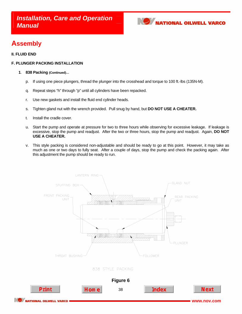
It is important that the following procedure be observed when replacing old packing to prevent rapid packing wear. Style 838 packing is assembled in units consisting of a pressure ring along with a top and bottom adapter. Each set will have two or three units. Pay attention to the arrangement of the old packing sets to ensure the new sets are installed correctly. Another check is the units are installed so the lantern ring is positioned under the lubrication port. If the lantern ring does not align with the lubrication port, the pump is not correctly packed.
a. Remove cradle cover and fluid end cylinder heads, then rotate pump to bring the first plunger to the forward
position. b. Back off gland nut one or two rounds.
c. If the pump has intermediate rods a back-up wrench is required. The plunger and intermediate rod separate at
the knurl area interface. Using the back-up wrench break the plunger loose and unscrew from the intermediate rod. Remove the plunger through the fluid cylinder opening.
d. If the pump does not have an intermediate rod, use a pipe wrench on the knurled area of the plunger and break
it loose from the crosshead. Unscrew and remove through the fluid cylinder opening. e. Remove the gland nut, old packing, and packing adapters. Note the order of the packing and adapters. Clean the
stuffing box and inspect for any damage. f. Rotate the pump to bring the next plunger forward. g. Repeat steps “b” through “f” until all the plungers and packing have been removed. h. Check the throat bushing, lantern ring, and follower for excessive wear. These items can often be reused, but if
they are worn, replace them. Reusing worn trim will cause premature packing failure. i. Lightly lubricate the stuffing box bore and install the throat bushing. j. Lightly lubricate a packing unit and install each component separately insuring each component is fully seated at the
bottom of the box before installing the next component. Repeat and install the second unit. (DO NOT GREASE) k. Install the lantern ring. Check to ensure the lubrication port is aligned with the lantern ring. If not, to few or to many
units have been installed ahead of the lantern ring. l. Install the last unit of packing. m. Install the follower ring and start the gland nut. Adjust the gland nut hand tight only. n. Lightly oil the plunger and install it through the fluid cylinder. Do not use worn plungers on new packing, as this will
shorten packing life. o. If using two piece plungers, torque the adapter rod into cross head to 100 ft.-lbs. (135 N-M). Then, use a back up
wrench on the adapter rod and torque the plunger into the adapter rod to 100 ft.-lbs. (135 N-M).
38
Installation, Care and Operation Manual
www.nov.com
Assembly II. FLUID END F. PLUNGER PACKING INSTALLATION
1. 838 Packing (Continued)…
p. If using one piece plungers, thread the plunger into the crosshead and torque to 100 ft.-lbs (135N-M). q. Repeat steps “h” through “p” until all cylinders have been repacked.
r. Use new gaskets and install the fluid end cylinder heads. s. Tighten gland nut with the wrench provided. Pull snug by hand, but DO NOT USE A CHEATER.
t. Install the cradle cover.
u. Start the pump and operate at pressure for two to three hours while observing for excessive leakage. If leakage is
excessive, stop the pump and readjust. After the two or three hours, stop the pump and readjust. Again, DO NOT USE A CHEATER.
v. This style packing is considered non-adjustable and should be ready to go at this point. However, it may take as
much as one or two days to fully seat. After a couple of days, stop the pump and check the packing again. After this adjustment the pump should be ready to run.
Figure 6
39
Installation, Care and Operation Manual
www.nov.com
Assembly… II. FLUID END F. PLUNGER PACKING INSTALLATION (Continued)…
2. BRAID PACKING
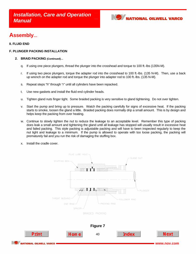
It is important that the following procedure be observed when replacing old packing to prevent rapid packing wear. Braided packing sets consist of braided packing rings, spacer rings, and end rings. The composition and number of rings vary depending on the fluid compatibility and stuffing box depth.
a. Remove cradle cover and fluid end cylinder heads, then rotate pump to bring the first plunger to the forward
position. b. Back off gland nut one or two rounds.
c. If the pump has intermediate rods a back-up wrench is required. The plunger and intermediate rod separate at
the knurl area interface. Using the back-up wrench break the plunger loose and unscrew from the intermediate rod. Remove the plunger through the fluid cylinder opening.
d. If the pump does not have an intermediate rod, use a pipe wrench on the knurled area of the plunger and break
it loose from the crosshead. Unscrew and remove through the fluid cylinder opening. e. Remove the gland nut, old packing, and packing adapters. Note the order of the packing and adapters. Clean the
stuffing box and inspect for any damage. f. Rotate the pump to bring the next plunger forward. g. Repeat steps “b” through “f” until all the plungers and packing have been removed. h. Check the throat bushing and follower for excessive wear. These items can often be reused, but if they are worn,
replace them. Reusing worn trim will cause premature packing failure. i. Ensure the stuffing box lube port is plugged or has not been drilled completely through. Braided packing does not
use a lantern ring and the port must be plugged or the packing can extrude through the port. j. Lightly lubricate the stuffing box bore and install the throat bushing. k. Install the first end ring into the box. Ensure it is fully seated against the bottom of the box and not cocked. l. Install the first pressure ring into the box and ensure it is fully seated. m. Install the spacer and ensure it is fully seated. n. Repeat this procedure until all the packing is installed and fully seated. ENSURE THE SPLITS ON EACH
PACKING RING ARE STAGGERED FROM THE PREVIOUS RING. DO NOT ALIGN THE SPLITS. o. Install the follower ring and loosely install the gland nut. p. Lightly oil the plunger and install it through the fluid cylinder. Do not use worn plungers on new packing, as this will
shorten packing life.
40
Installation, Care and Operation Manual
www.nov.com
Assembly… II. FLUID END F. PLUNGER PACKING INSTALLATION
2. BRAID PACKING (Continued)…
q. If using one piece plungers, thread the plunger into the crosshead and torque to 100 ft.-lbs (135N-M). r. If using two piece plungers, torque the adapter rod into the crosshead to 100 ft.-lbs. (135 N-M). Then, use a back
up wrench on the adapter rod and torque the plunger into adapter rod to 100 ft.-lbs. (135 N-M). s. Repeat steps “h” through “r” until all cylinders have been repacked.
t. Use new gaskets and install the fluid end cylinder heads. u. Tighten gland nuts finger tight. Some braided packing is very sensitive to gland tightening. Do not over tighten. v. Start the pump and bring up to pressure. Watch the packing carefully for signs of excessive heat. If the packing
starts to smoke, loosen the gland a little. Braided packing does normally drip a small amount. This is by design and helps keep the packing from over heating.
w. Continue to slowly tighten the nut to reduce the leakage to an acceptable level. Remember this type of packing
does leak a small amount and tightening the gland until all leakage has stopped will usually result in excessive heat and failed packing. This style packing is adjustable packing and will have to been inspected regularly to keep the nut tight and leakage to a minimum. If the pump is allowed to operate with too loose packing, the packing will prematurely fail and you run the risk of damaging the stuffing box.
x. Install the cradle cover.
Figure 7
41
Installation, Care and Operation Manual
www.nov.com
Assembly… II. FLUID END F. PLUNGER PACKING INSTALLATION (Continued)…
3. 1068-4 PACKING
1068-4 packing is spring loaded, molded V-ring style packing. It is normally used in reverse osmosis services, but may be used in other selected applications. This is non-adjustable packing.
a. Remove cradle cover and fluid end cylinder heads, then rotate pump to bring the first plunger to the forward
position. b. Back off gland nut one or two rounds.
c. If the pump has intermediate rods a back-up wrench is required. The plunger and intermediate rod separate at
the knurl area interface. Using the back-up wrench break the plunger loose and unscrew from the intermediate rod. Remove the plunger through the fluid cylinder opening.
d. If the pump does not have an intermediate rod, use a pipe wrench on the knurled area of the plunger and break
it loose from the crosshead. Unscrew and remove through the fluid cylinder opening. e. Remove the gland nut, old packing, and packing adapters. Note the order of the packing and adapters. Clean the
stuffing box and inspect for any damage. f. Rotate the pump to bring the next plunger forward. g. Repeat steps “b” through “f” until all the plungers and packing has been removed. h. Check the throat bushing and follower for excessive wear. These items can often be reused, but if they are worn,
replace them. Reusing worn trim will cause premature packing failure. i. Ensure the stuffing box lube port is plugged or has not been drilled completely through. 1068-4 packing does not
use a lantern ring and the port must be plugged or the packing can extrude through the port. j. Lightly lubricate the stuffing box bore and install the throat bushing, if used. k. Install the packing spring.
l. Lubricate and install the packing set and adapters.
m. Install the follower ring (if used) and gland nut. Do not fully tighten the gland nut at this time.
n. Lightly oil the plunger and install it through the fluid cylinder. Do not use worn plungers on new packing, as this will
shorten packing life.
o. If using one piece plungers, thread the plunger into the crosshead and torque to 100 ft.-lbs (135N-M).
p. If using two piece plungers, torque the adapter rod into the crossed 100 ft.-lbs. (135 N-M). Then, use a back up wrench on the adapter rod and torque the plunger into adapter rod 100 ft.-lbs. (135 N-M).
q. Repeat steps “h” through “p” until all cylinders have been repacked.
42
Installation, Care and Operation Manual
www.nov.com
Assembly… II. FLUID END F. PLUNGER PACKING INSTALLATION
3. 1068-4 PACKING (Continued)…
r. Using the standard gland wrench tighten all glands completely. The glands will pull completely up. Again, this packing is spring-loaded and non-adjustable so once the glands are properly pulled up there is no more adjustment.
s. Install the cradle cover.
Figure 8
43
Installation, Care and Operation Manual
www.nov.com
Plunger Pump Valves… I. OPERATIONAL MAINTENANCE A. SUCTION AND DISCHARGE
As with any plunger pump, the necessity for having an adequate suction head and proper piping design of both suction and discharge cannot be over emphasized.
! ATTENTION !
NOISY VALVES, DUE TO IMPROPER FILLING, CAN LEAD TO SHORT LIFE AND RAPID MECHANICAL WEAR OF THE POWER END PARTS.
B. VALVE COVERS
THE VALVE COVERS, AS USED WITH THE NATIONAL OILWELL VARCO PLUNGER PUMPS, MUST BE KEPT TIGHT AT ALL TIMES. DUE TO THE DISCHARGE PRESSURE APPLYING A CONSTANT LOAD TO THE COVERS, IT IS NOT POSSIBLE TO CHECK THEIR TIGHTNESS WITH THE PUMP RUNNING OR WITH PRESSURE IN THE CYLINDER. Bleed off the discharge pressure and check the tightness of the covers as outlined under the assembly procedure for the type of cover used.
C. VALVE COVER SEALS
Tapered Seat Valves: The cover seals should be replaced as required. D. VALVE SPRINGS
The springs used with the NATIONAL OILWELL VARCO valves are made of inconel alloy or other stainless steel.
! ATTENTION !
THESE SPRINGS SHOULD BE CHANGED APPROXIMATELY ONCE A YEAR IN ORDER TO ASSURE PROPER VALVE ACTION AND ELIMINATE THE POSSIBILITY OF A SPRING BREAK.
E. VALVE AND SEAT
Tapered Seat Valves: There are four basic valve and seat assemblies available, depending on the type of service. They are the severe duty (abrasion resistant) tapered seat valves, the disc tapered seat valves, the spherical tapered seats, and the spherical severe duty tapered seat valves.
CAUTION
44
Installation, Care and Operation Manual
www.nov.com
Plunger Pump Valves (Continued)… II. TAPERED SEAT VALVES A. SEVERE DUTY TYPE VALVES
This section will assist in servicing the severe duty (abrasion resistant) valve in your National Oilwell Varco multiplex pump. 1. NOMENCLATURE.
SEVERE DUTY VALVE ASSEMBLY
VALVE BODYTHREAD LOCK
INSERT
SPRING RETAINER
SEAT
NOMENCLATURE
For part numbers and pullers see the following table.
Plunger Pump Valves… II. TAPERED SEAT VALVES A. SEVERE DUTY TYPE VALVES (Continued)…
2. VALVE REMOVAL PROCEDURES
a. Ensure pressure is removed from fluid end and pump is “LOCKED OUT”. b. The discharge valve is removed through the valve cover and the suction valve is removed through the cylinder
head. Remove both covers. c. Rotate the pump so the plunger for the cylinder you are working on is all the way back. d. Starting with the discharge valve assembly use the cage wrench (See tools section of parts list for special tools
and numbers) and remove the valve retainer by turning the wrench counter-clockwise. e. Remove the valve spring. f. Remove the valve body. g. Use the special valve puller and remove the valve seat. See illustration.
h. Repeat steps “c” through “g” for the suction valve assembly.
Figure 9
46
Installation, Care and Operation Manual
www.nov.com
Plunger Pump Valves… II. TAPERED SEAT VALVES A. SEVERE DUTY TYPE VALVES (Continued)…
3. VALVE PARTS INSPECTION
SEVERE DUTY VALVE ASSEMBLY
VALVE BODYTHREAD LOCK
INSERT
SPRING RETAINER
SEAT
NOMENCLATURE
a. RETAINER The retainer will not need to be replaced very often. It should be inspected for corrosion or to see if it has been
warped or bent. If this is the case, replace the retainer because this can cause undue wear on the spring and improper valve action.
b. SPRING The spring is made from inconel or other stainless steel and will work in most corrosive environments. It should
be inspected for wear and/or nicks. If such evidence is apparent, the spring should be replaced.
47
Installation, Care and Operation Manual
www.nov.com
Plunger Pump Valves… II. TAPERED SEAT VALVES A. SEVERE DUTY TYPE VALVES
3. VALVE PARTS INSPECTION (Continued)…
c. INSERT The valve insert is made from polyurethane. A good insert is vital for good sealing in slurries or dirty fluids.
Inspect the insert for tears, nibbling, and extrusion. If the insert is worn, replace it. Generally you can replace the insert a couple of times before having to replace the valve body.
d. THREAD LOCK The thread lock is a nitrile rubber. It is used to lock the retainer and prevent it from backing off during pump
operation. If the thread lock is torn or damaged, replace it. e. VALVE BODY The valve body is heat-treated 17-4 PH stainless. Inspect the body for excessive wear, cracks, or washing. The
guides should also be inspected for proper fit in the seat and any cracks or excessive wear. Replace the valve body when these conditions are present. If replacing the valve body, a new insert should also be used.
f. SEAT The seat is also a heat-treated 17-4 PH stainless steel. Is should be inspected for excessive wear and/or wash
on the seating surface. Also check the taper for signs of wash by or wear. If any of these conditions exist, the seat should be replaced. Do not use an old valve body with a new seat.
With the seat out of the pump also inspect the liquid end seating area for washing or excessive wear. The seats
should fit in the liquid end with a small amount of stand off. If the liquid end seating area is washed or there is no stand off on the seats, the liquid end will have to be repaired. This type of repair will require the services of a machine shop.
4. VALVE INSTALLATION PROCEDURES
a. Thoroughly clean the fluid cylinder seat area with a cleaner that will not leave an oily residue. Do not oil the taper area of the seat or fluid cylinder seating area. This will cause the seat to “jump out” of the bore and could cause major damage to the pump.
b. Clean the taper on the suction seat using the same precautions as with the fluid cylinder bore. The two surfaces
must be clean and dry before assembly.
c. Insert the suction seat into the fluid cylinder suction bore.
d. Using a metal plate or old worn valve body, drive the seat into place with several sharp blows from a hammer and bar. (See illustration)
48
Installation, Care and Operation Manual
www.nov.com
Plunger Pump Valves… II. TAPERED SEAT VALVES A. SEVERE DUTY TYPE VALVES
4. VALVE INSTALLATION PROCEDURES (Continued)…
FIGURE 10
e. Install the new valve body with insert. f. Install the spring. g. Using the cage wrench (See parts list for special tools) install the retainer cage. h. Repeat this procedure for the discharge valve.
I. Repeat until all valve assemblies have been installed.
49
Installation, Care and Operation Manual
www.nov.com
Plunger Pump Valves… II. TAPERED SEAT VALVES (Continued)… B. DISK TAPERED SEAT VALVES
1. NOMENCLATURE
VALVE DISC
SEAT
OUTER SPRING
FASTENERRETAINER
INNER SPRING
NOMENCLATURE
For part numbers and pullers see the following table.
Plunger Pump Valves… II. TAPERED SEAT VALVES B. DISK TAPERED SEAT VALVES (Continued)…
2. VALVE REMOVAL PROCEDURES
a. Ensure pressure is removed from the fluid end and pump is “Locked out”. b. The discharge valve is removed through the valve cover and the suction valve is removed through the cylinder
head. Remove both covers. c. Rotate the pump so the plunger for the cylinder you are working on is all the way back. d. Starting with the discharge valve assembly remove the cap screw holding the retainer in place. e. Remove the retainer and valve springs. f. Remove the valve disc. g. Use the special valve puller and remove the seat. See Figure 11. h. Repeat steps “c” through “g” for the suction valve assembly.
FIGURE 11
51
Installation, Care and Operation Manual
www.nov.com
Plunger Pump Valves… II. TAPERED SEAT VALVES B. DISK TAPERED SEAT VALVES (Continued)…
3. VALVE PARTS INSPECTION
a. FASTENER The fastener has a nylon lock tab or a lock patch. Inspect the fastener for corrosion, damaged threads,
straightness, and condition of the locking tab. If the fastener is damaged, replace it. The locking tab can be used more than once. However, if the resistance when the tab engages the thread is minimal, replace it.
b. RETAINER The retainer will not need to be replaced very often. It should be inspected for corrosion or to see if it has been
warped or bent. If this is the case, replace the retainer because this can cause undue wear on the springs and improper valve action.
c. SPRING The springs are made from inconel or other stainless steel and will work in most corrosive environments. It
should be inspected for wear and/or nicks. If such evidence is apparent, the springs should be replaced. d. VALVE DISC The valve disc is either “Delrin” or Titanium. Inspect the disc for excessive wear, cracks, or washing. If any of
these conditions exist, replace the disc. e. SEAT The seat should be inspected for excessive wear and/or wash on the seating surface. Also check the webs for
any cracks and the thread for any tears or damaged threads. Check the taper for any signs of wash. Replace the seat if these conditions exist.
4. VALVE INSTALLATION PROCEDURES
a. Thoroughly clean the fluid cylinder seat area with a cleaner that will not leave an oily residue. Do not oil the taper area of the seat or fluid cylinder seating area. This will cause the seat to “jump out” of the bore and could cause major damage to the pump.
b. Clean the taper on the suction seat using the same precautions as with the fluid cylinder bore. The two surfaces
must be clean and dry before assembly. c. Insert the suction seat into the fluid cylinder suction bore.
52
Installation, Care and Operation Manual
www.nov.com
Plunger Pump Valves… II. TAPERED SEAT VALVES B. DISK TAPERED SEAT VALVES
4. VALVE INSTALLATION PROCEDURES (Continued)…
d. Using a metal plate or old worn valve body, drive the seat into place with several sharp blows from a hammer
and bar. (See Figure 12)
FIGURE 12
e. Install the valve disc. f. Install the valve springs. g. Install the retainer. h. With one hand push the retainer down to compress the springs and start the neck of the retainer through the
valve disc. Hand start the fastener. i. Tighten the fastener while insuring the retainer pulls down against the seat and does not clamp the disc down.
The disc has to move up and down on the retainer neck. j. Repeat this procedure for the discharge valve. k. Repeat for the remaining cylinders.
53
Installation, Care and Operation Manual
www.nov.com
Plunger Pump Valves… II. TAPERED SEAT VALVES C. SPHERICAL VALVES (Continued)…
1. NOMENCLATURE
SPHERICAL VALVE ASSEMBLY
NOMENCLATURE
RETAINER SPRING
VALVE BODY
SEAT
WAVE RING
For part numbers and pullers see the following table.
Plunger Pump Valves… II. TAPERED SEAT VALVES C. SPHERICAL VALVES (Continued)…
2. VALVE REMOVAL PROCEDURE
a. Ensure pressure is removed from fluid end and pump is “LOCKED OUT”.
b. The discharge valve is removed through the valve cover and the suction valve is removed through the cylinder head. Remove both covers.
c. Rotate the pump so the plunger for the cylinder you are working on is all the way back. d. Remove the spring retainer by pressing downward on the puller head and turn counter clockwise about 1/8 of a
turn or until retainer stops. Remove the retainer with the retriever. See Figure 30. e. Remove spring(s) and valve with the retriever. See Figure 31. f. Remove seat by placing the puller head through the seat opening and engage lugs to the underside of the seat.
Pull seat or bump seat loose and remove. See Figure 32. g. Repeat steps “c” through “f” for the suction valve assembly.
3. VALVE PARTS INSPECTION
a. RETAINER The retainer will not need to be replaced very often. It should be inspected for corrosion or to see if it has been
warped or bent. If this is the case, replace the retainer because this can cause undue wear on the springs and improper valve action.
b. SPRING The springs are made from inconel or other stainless steel and will work in most corrosive environments. It
should be inspected for wear and/or nicks. If such evidence is apparent, the spring should be replaced. c. VALVE BODY The valve body is a stainless steel spherical disc. Inspect the valve for excessive wear, cracks, or washing. If
any of these conditions exist, replace the valve. d. SEAT The seat is stainless steel and should be inspected for excessive wear and/or wash on the seating surface. Also
check the lugs, which engage the retainer for any damage. Check the taper for any signs of wash. Replace if these conditions exist.
e. WAVE RING The wave rings protects the valve integrity and is a safety device to prevent the cage from coming loose in the
rare event a spring breaks. Check the wave ring for cracks or damage. Replace if necessary.
55
Installation, Care and Operation Manual
www.nov.com
Plunger Pump Valves… II. TAPERED SEAT VALVES C. SPHERICAL VALVES
4. VALVE INSTALLATION PROCEDURE (Continued)…
a. Thoroughly clean the cylinder taper with a cleaner that will not leave an oily residue. Do not oil the taper area of the seat or fluid cylinder seating area. This will cause the seat to “jump out”
b. Clean the taper on the suction seat using the same precautions as with the fluid cylinder bore. The two surfaces
must be clean and dry before assembly. c. Inspect for corrosion or damaged areas. Repair or replace as required. d. Place seat in the suction bore making certain it is straight. e. With a bar and a driver tap seat in place with 2 or 3 strokes. NOTE!! Seat does not have to be completely
seated. Pump start-up pressure will drive seat home. See Figure 17. f. Install valve, spring(s), and spring retainer. See Figure 18.
56
Installation, Care and Operation Manual
www.nov.com
Plunger Pump Valves… II. TAPERED SEAT VALVES C. SPHERICAL VALVES
4. VALVE INSTALLATION PROCEDURE (Continued)…
Figure 13 Figure 14 Figure 15 Figure 16
Figure 17 Figure 18
57
Installation, Care and Operation Manual
www.nov.com
Plunger Pump Valves… II. TAPERED SEAT VALVES (Continued)… D. SPHERICAL VALVES – SEVERE DUTY
1. NOMENCLATURE
INSERT
WAVE RING
NOMENCLATURE
SPHERICAL - SEVERE DUTY ASSEMBLY
For part numbers and pullers see the following table.
Plunger Pump Valves II. TAPERED SEAT VALVES D. SPHERICAL VALVES – SEVERE DUTY (Continued)…
2. VALVE REMOVAL PROCEDURE
a. Ensure pressure is removed from fluid end and pump is “LOCKED OUT”.
b. The discharge valve is removed through the valve cover and the suction valve is removed through the cylinder head. Remove both covers.
c. Rotate the pump so the plunger for the cylinder you are working on is all the way back. d. Remove the spring retainer by pressing downward on the puller head and turn counter clockwise about 1/8 of a
turn or until retainer stops. Remove the retainer with the retriever. See Figure 14. e. Remove spring(s) and valve with the retriever. See Figure 15. f. Remove seat by placing the puller head through the seat opening and engage lugs to the underside of the seat.
Pull seat or bump seat loose and remove. See Figure 16. g. Repeat steps “c” through “f” for the suction valve assembly.
3. VALVE PARTS INSPECTION
a. RETAINER The retainer will not need to be replaced very often. It should be inspected for corrosion or to see if it has been
warped or bent. If this is the case, replace the retainer because this can cause undue wear on the springs and improper valve action.
b. SPRING The springs are made from inconel or other stainless steel and will work in most corrosive environments. It
should be inspected for wear and/or nicks. If such evidence is apparent, the spring should be replaced. c. VALVE BODY The valve body is a stainless steel spherical disc. Inspect the valve for excessive wear, cracks, or washing. If
any of these conditions exist, replace the valve. d. INSERT The standard insert is poly urethane and is used when solids are present in the fluid. Inspect the insert for
cracks or tears. If damaged replace. e. SEAT The seat is stainless steel and should be inspected for excessive wear and/or wash on the seating surface. Also
check the lugs, which engage the retainer for any damage. Check the taper for any signs of wash. Replace if these conditions exist.
59
Installation, Care and Operation Manual
www.nov.com
Plunger Pump Valves… II. TAPERED SEAT VALVES D. SPHERICAL VALVES – SEVERE DUTY
3. VALVE PARTS INSPECTION (Continued)… f. WAVE RING The wave rings protects the valve integrity and is a safety device to prevent the cage from coming loose in the
rare event a spring breaks. Check the wave ring for cracks or damage. Replace if necessary.
4. VALVE INSTALLATION PROCEDURE
a. Thoroughly clean the cylinder taper with a cleaner that will not leave an oily residue. Do not oil the taper area of the seat or fluid cylinder seating area. This will cause the seat to “jump out”
b. Clean the taper on the suction seat using the same precautions as with the fluid cylinder bore. The two surfaces
must be clean and dry before assembly. c. Inspect for corrosion or damaged areas. Repair or replace as required. d. Place seat in the suction bore making certain it is straight. e. With a bar and a driver tap seat in place with 2 or 3 strokes. NOTE!! Seat does not have to be completely
seated. Pump start-up pressure will drive seat home. See Figure 17. f. Install valve, spring(s), and spring retainer. See Figure 18.
• Remove the vent screw and fill the sight glass with oil. Prime by manually pumping flushing unit until air free oil is observed from the drip tube and oil level drops in the sight glass.
• Replace vent screw and tighten union nut.
• Maintain oil level in sight glass below the drip tube so drops can be observed.
2. FLOW RATE ADJUSTMENT
• Loosen locknut on flushing unit.
• Turn flushing unit counter-clockwise to increase flow.
• Turn flushing unit clockwise to decrease flow.
• Tighten locknut when desired flow rate is achieved. 3. SIGHT GLASS
In a vacuum type sight feed, it is not uncommon for oil level in the sight glass to drop during operation. Absence of a level indicates air is being taken in with the oil and some oils, due to viscosity conditions, will release air faster than others. When the quality of air becomes excessive, it can eventually air lock the pump.
For this reason it is recommended that an oil level in
the sight glass be maintained. When level drops, remove the vent screw and fill
sight glass to top; replace vent screw and operate flushing unit manually, observing that an oil in the sight glass is free from air. If air is not expelled, it may be necessary to loosen union nut (on pump outlet) and expel air at this point. It is desirable to maintain level below the drip tube so drops can be seen during operation.
4. OVERFILLING OF SIGHT GLASS
In a vacuum type sight feed, it is not uncommon to see a reverse action whereas sight glass fills with oil and the drops cannot be observed. Overfilling is caused by oil absorbing air in the sight glass and normally does not affect the operation of the pump. Remove the vent screw from sight glass and allow level to drop below drip tube. Tighten vent screw and check to see that air free oil from drip tube can be observed in the sight glass. If overfilling continues, it may be caused by plunger wear and oil slippage is being drawn back to sight glass. If this is the problem, the feed setting in drops per stroke will then automatically be reduced by the amount of slippage.
5. RESERVOIR OIL LEVEL (LOSS OF PRIME)
If reservoir runs low on oil (at a point below the suction inlet of the pump) it may be necessary to prime individual pumps after filling, using procedure listed above.
The cubic volume for a pint of oil is 28.9 cubic inches
and average drop size is .002 cubic inches.
Vent Screw Pump Outlet, 1/8” NPT
Union Nut
Sight Glass
Flushing Unit
Lock Nut
Suction Inlet
With over 120 locations worldwide, National Oilwell Varco is located near you. To find the nearest Distribution Service Center, machinery center or repair facility,
please give us a call at our main office listed below.
Or you can access our website at the URL listed below, where you may search by location or country.
http://www.nov.com/contactus/
Sales/Technical Information: USA Tollfree: 1 (800) 324-4706 Internet: http://www.nov.com
National Oilwell Varco is a leading manufacturer of reciprocating plunger pumps, Mission Fluid King centrifugal pumps, and fluid end replacement parts. We also offer a complete set of solutions to your fluid transfer challenges. For more Information, contact National Oilwell Varco directly at the Headquarters in Houston, Texas. All National Oilwell Varco products are available throughout the U.S. and around the world from service centers, authorized distributors, and representatives.