36
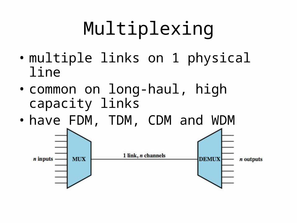
Multiplexing • multiple links on 1 physical line • common on long-haul, high capacity links • have FDM, TDM, CDM and WDM
| Date post: | 25-Dec-2015 |
| Category: |
Documents |
| Upload: | garey-wilkerson |
| View: | 218 times |
| Download: | 0 times |
Multiplexing
• multiple links on 1 physical line• common on long-haul, high capacity links• have FDM, TDM, CDM and WDM
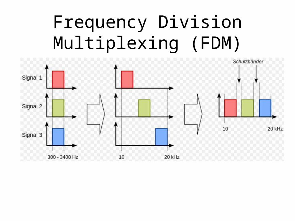
Frequency Division Multiplexing (FDM)
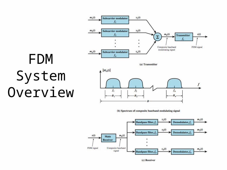
FDMSystem
Overview
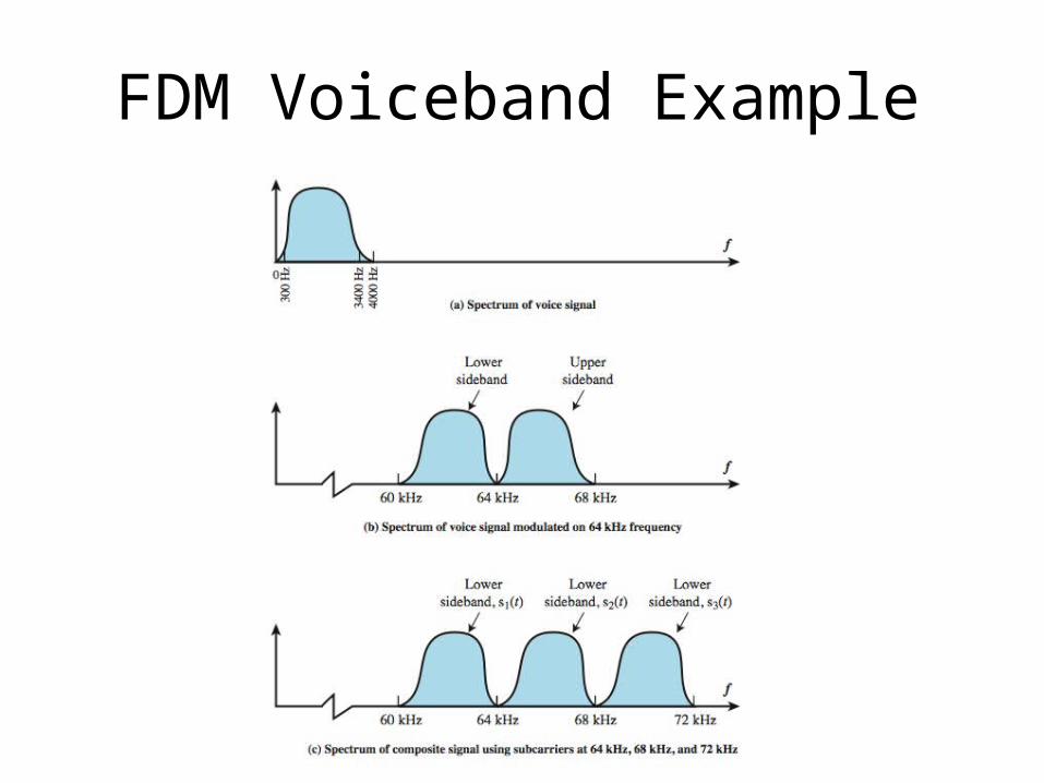
FDM Voiceband Example
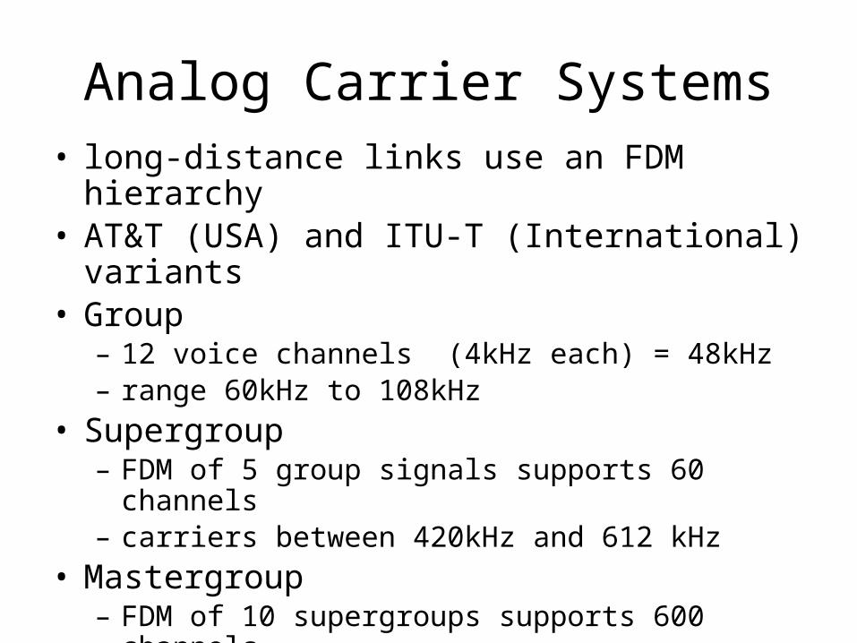
Analog Carrier Systems• long-distance links use an FDM hierarchy• AT&T (USA) and ITU-T (International) variants• Group
– 12 voice channels (4kHz each) = 48kHz– range 60kHz to 108kHz
• Supergroup– FDM of 5 group signals supports 60 channels– carriers between 420kHz and 612 kHz
• Mastergroup– FDM of 10 supergroups supports 600 channels
• original signal can be modulated many times
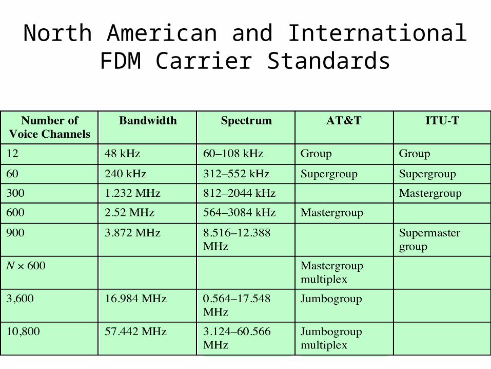
North American and International FDM Carrier Standards
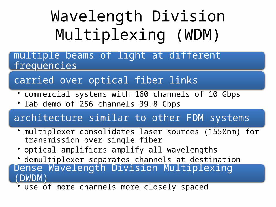
Wavelength Division Multiplexing (WDM)
multiple beams of light at different frequencies
carried over optical fiber links• commercial systems with 160 channels of 10 Gbps• lab demo of 256 channels 39.8 Gbps
architecture similar to other FDM systems• multiplexer consolidates laser sources (1550nm) for transmission
over single fiber• optical amplifiers amplify all wavelengths• demultiplexer separates channels at destination
Dense Wavelength Division Multiplexing (DWDM)• use of more channels more closely spaced
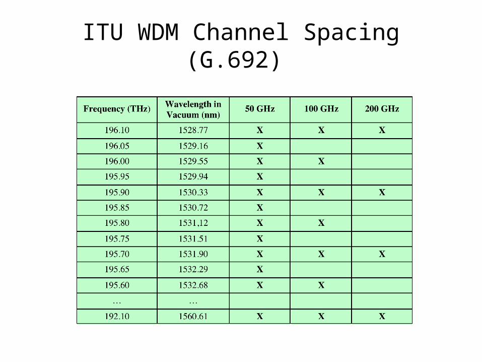
ITU WDM Channel Spacing (G.692)
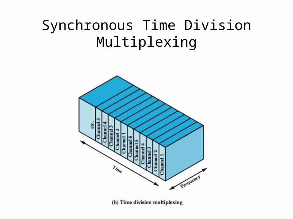
Synchronous Time Division Multiplexing
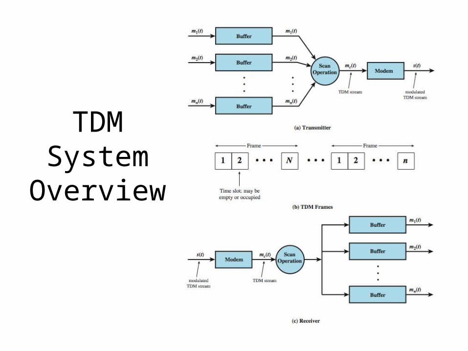
TDM System
Overview
TDM Link Control
• no headers and trailers• data link control protocols not needed• flow control
– data rate of multiplexed line is fixed– if one channel receiver can not receive data, the
others must carry on– corresponding source must be quenched– leaving empty slots
• error control– errors detected & handled on individual channel
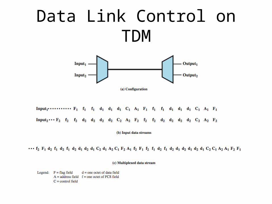
Data Link Control on TDM
Framing
• no flag or SYNC chars bracketing TDM frames• must still provide synchronizing mechanism
between source and destination clocks• added digit framing is most common
– one control bit added to each TDM frame– identifiable bit pattern used as control channel– alternating pattern 101010…unlikely to be sustained
on a data channel– receivers compare incoming bits of frame position to
the expected pattern
Pulse Stuffing
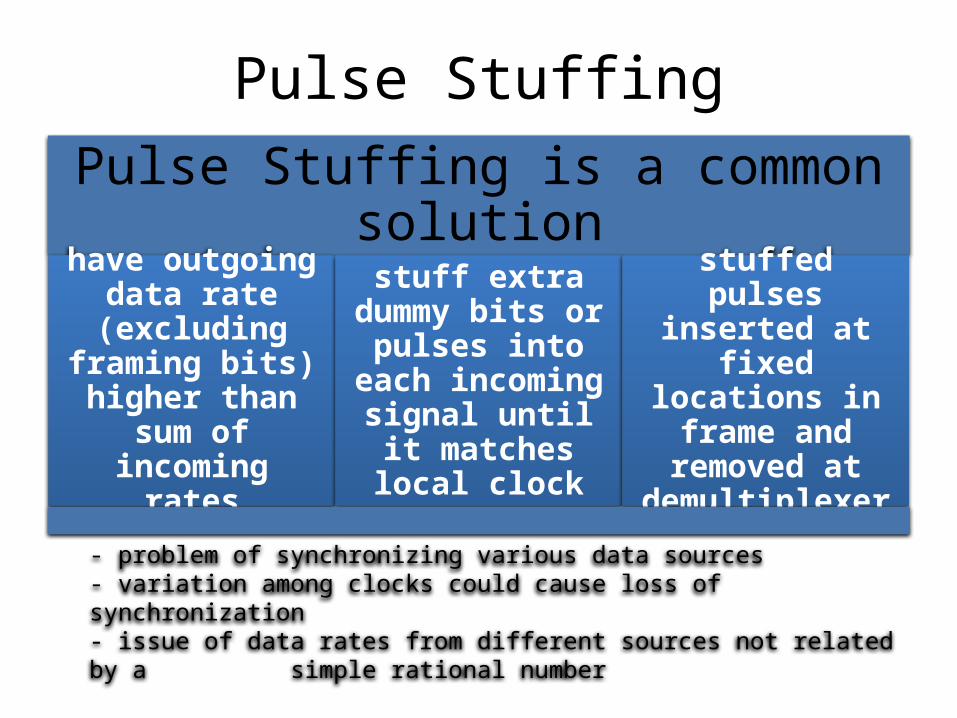
Pulse Stuffing is a common solution
have outgoing data rate
(excluding framing bits)
higher than sum of incoming rates
stuff extra dummy bits or
pulses into each incoming signal until it matches
local clock
stuffed pulses inserted at fixed
locations in frame and
removed at demultiplexer
- problem of synchronizing various data sources- variation among clocks could cause loss of synchronization- issue of data rates from different sources not related by a simple rational number
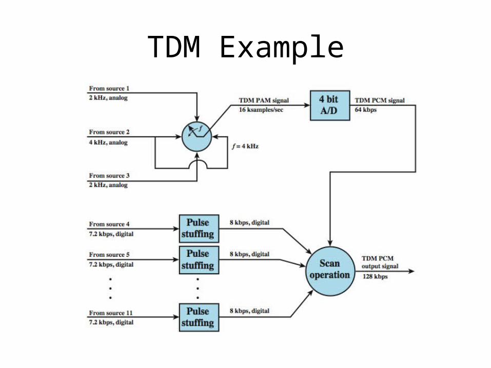
TDM Example
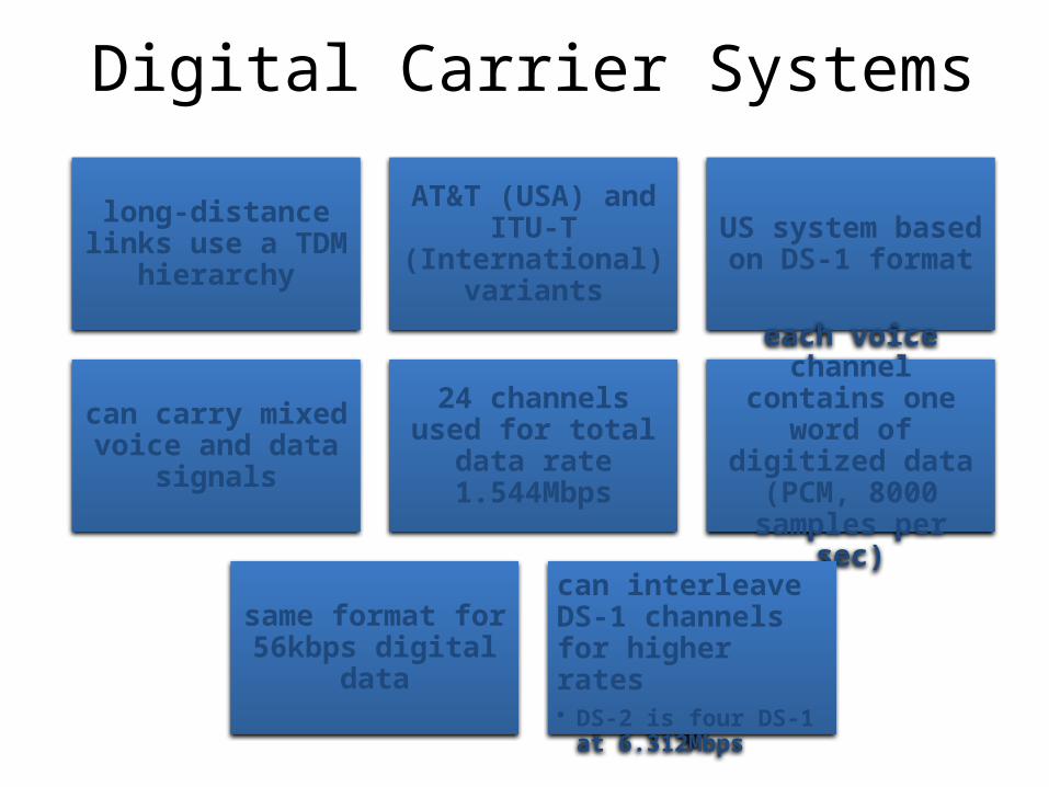
Digital Carrier Systems
long-distance links use a TDM hierarchy
AT&T (USA) and ITU-T
(International) variants
US system based on DS-1 format
can carry mixed voice and data
signals
24 channels used for total data rate
1.544Mbps
each voice channel contains one word
of digitized data (PCM, 8000
samples per sec)
same format for 56kbps digital data
can interleave DS-1 channels for higher rates• DS-2 is four DS-1 at
6.312Mbps
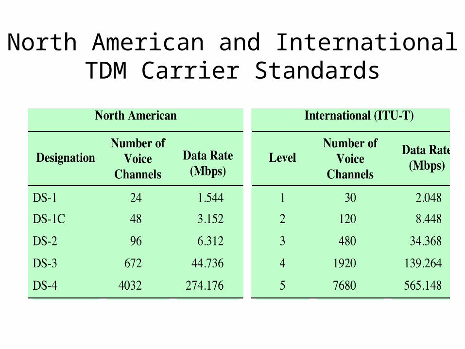
North American and International TDM Carrier Standards
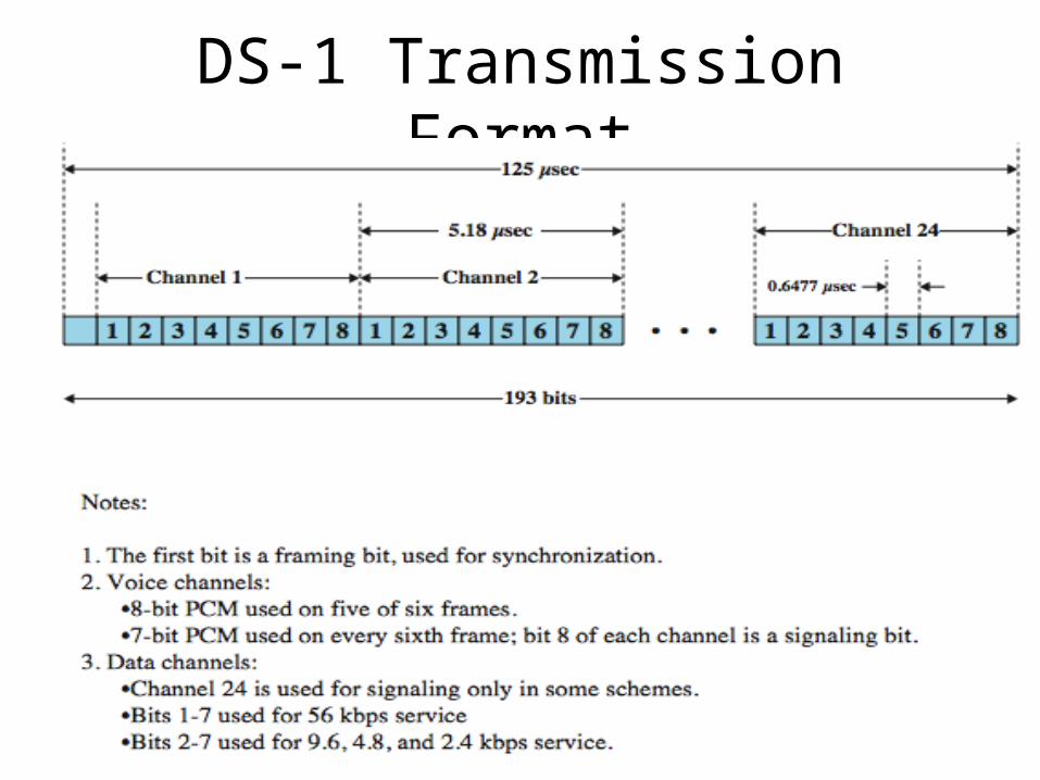
DS-1 Transmission Format
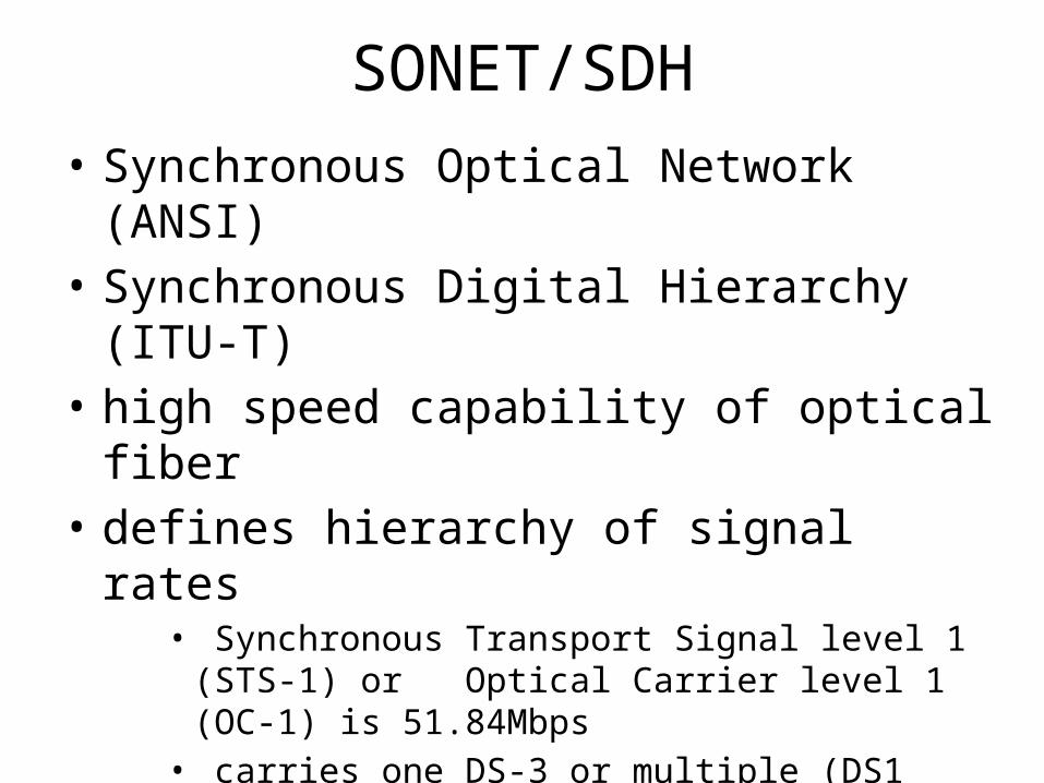
SONET/SDH
• Synchronous Optical Network (ANSI)• Synchronous Digital Hierarchy (ITU-T)• high speed capability of optical fiber• defines hierarchy of signal rates
• Synchronous Transport Signal level 1 (STS-1) or Optical Carrier level 1 (OC-1) is 51.84Mbps
• carries one DS-3 or multiple (DS1 DS1C DS2) plus ITU-T rates (e.g., 2.048Mbps)
• multiple STS-1 combine into STS-N signal• ITU-T lowest rate is 155.52Mbps (STM-1)
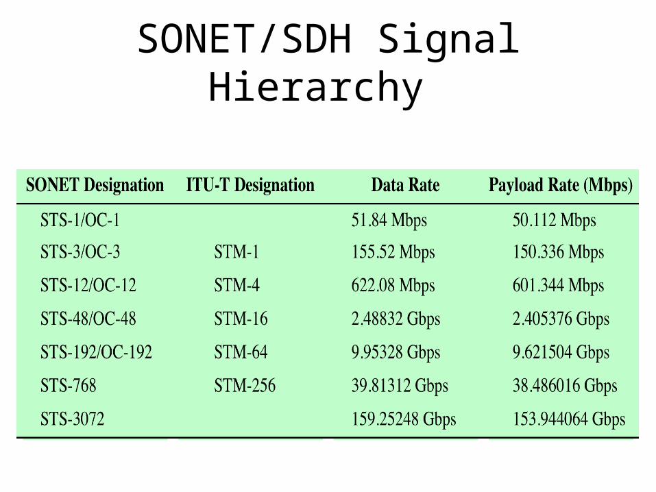
SONET/SDH Signal Hierarchy
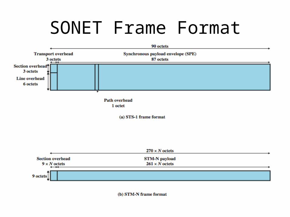
SONET Frame Format
Statistical TDM
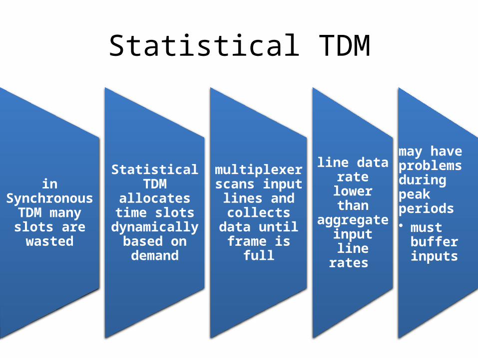
in Synchronous
TDM many slots are wasted
Statistical TDM
allocates time slots
dynamically based on demand
multiplexer scans input
lines and collects data until frame is
full
line data rate lower
than aggregate input line
rates
may have problems during peak periods• must
buffer inputs
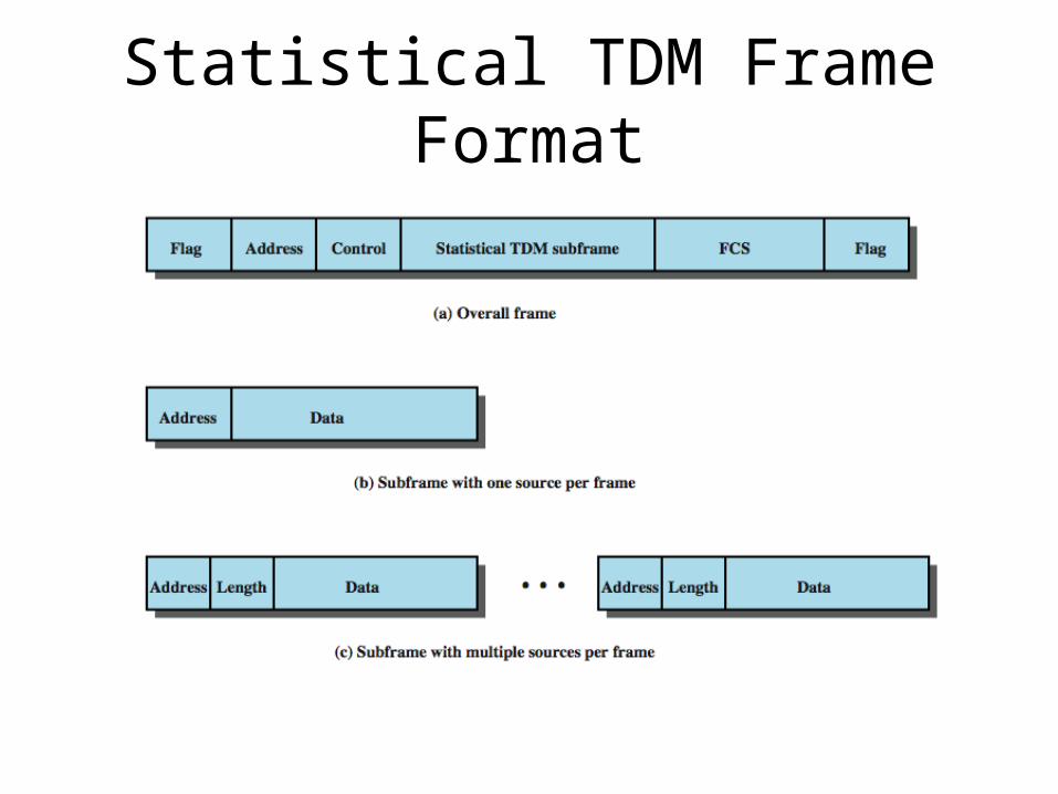
Statistical TDM Frame Format
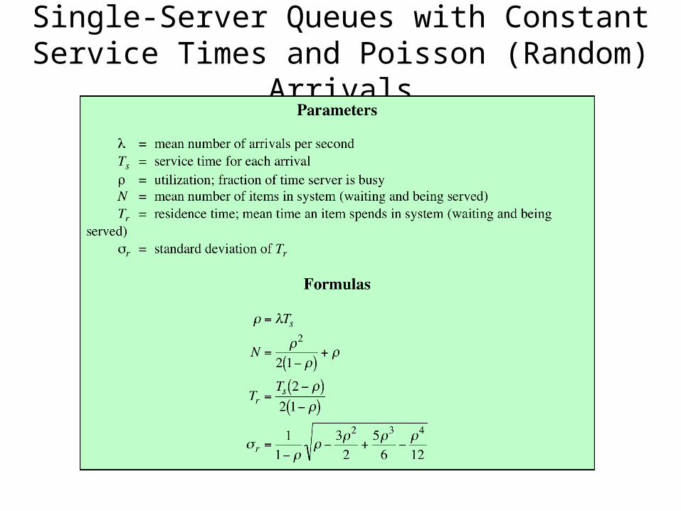
Single-Server Queues with Constant Service Times and Poisson (Random) Arrivals
Cable Modems
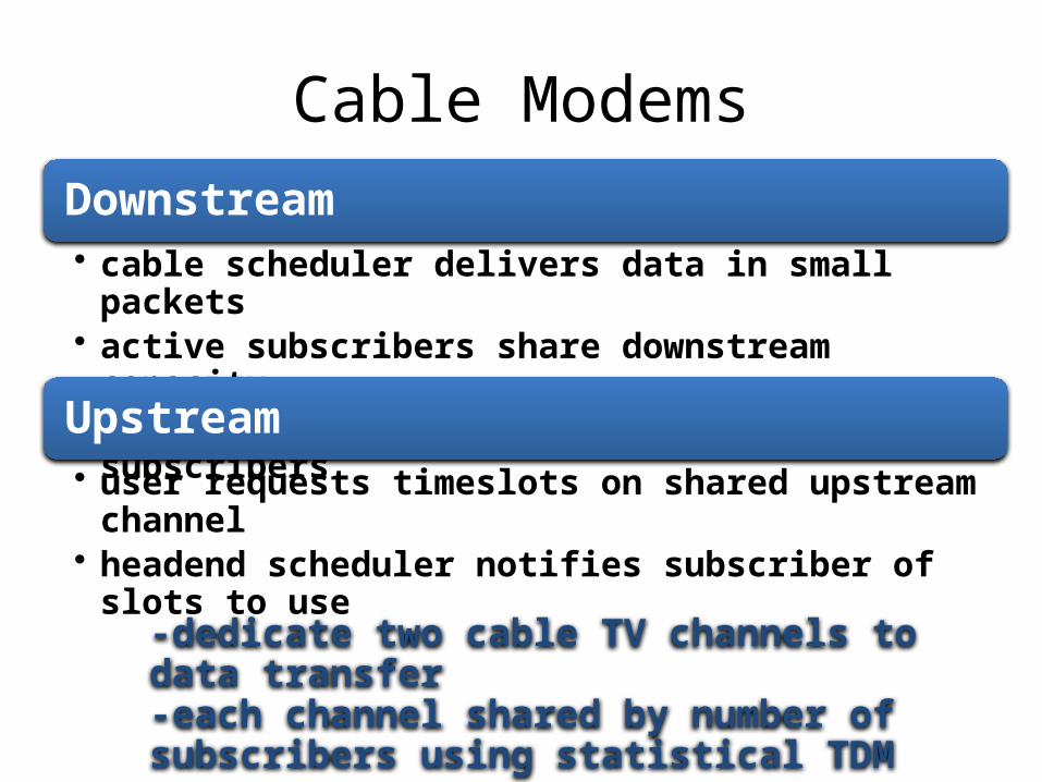
Downstream• cable scheduler delivers data in small packets• active subscribers share downstream capacity• also allocates upstream time slots to subscribers
Upstream• user requests timeslots on shared upstream channel• headend scheduler notifies subscriber of slots to
use
-dedicate two cable TV channels to data transfer-each channel shared by number of subscribers using statistical TDM
Cable Spectrum Division
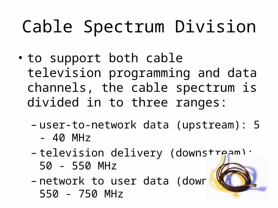
• to support both cable television programming and data channels, the cable spectrum is divided in to three ranges:
– user-to-network data (upstream): 5 - 40 MHz– television delivery (downstream): 50 - 550 MHz– network to user data (downstream): 550 - 750
MHz
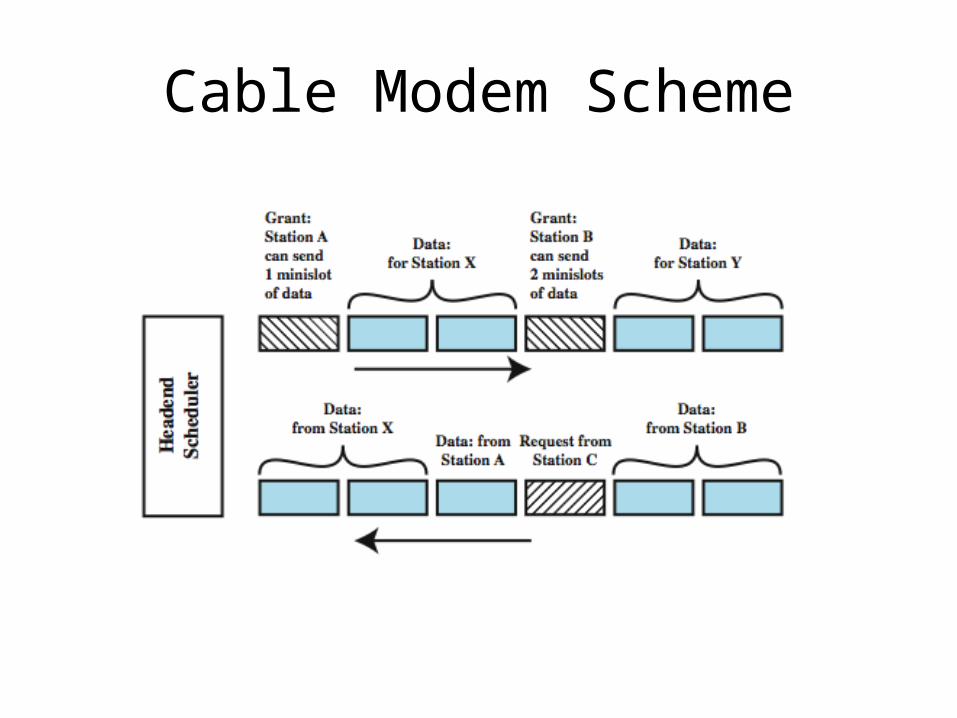
Cable Modem Scheme
Asymmetrical Digital Subscriber Line (ADSL)
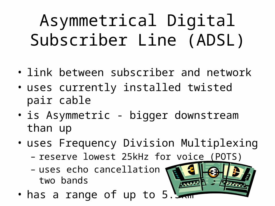
• link between subscriber and network• uses currently installed twisted pair cable• is Asymmetric - bigger downstream than up• uses Frequency Division Multiplexing
– reserve lowest 25kHz for voice (POTS)– uses echo cancellation or FDM to give two bands
• has a range of up to 5.5km
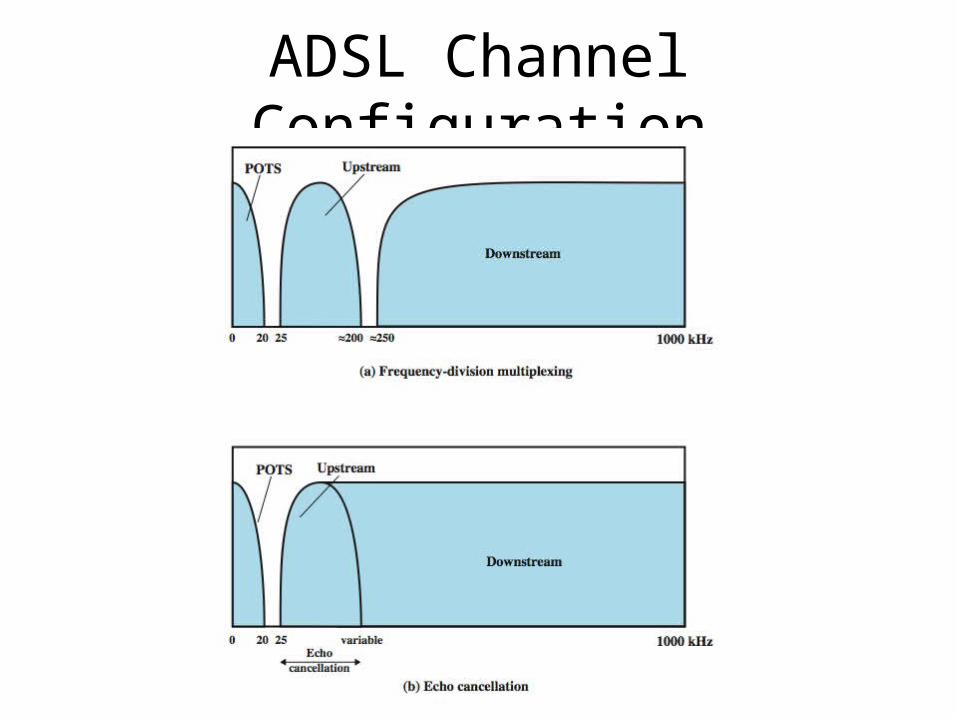
ADSL Channel Configuration
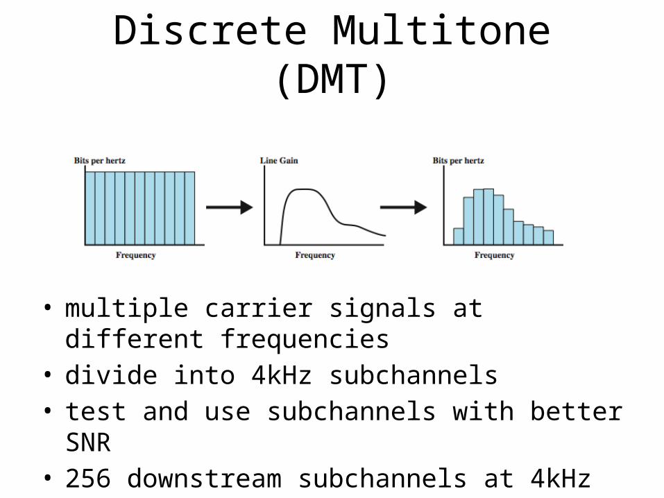
Discrete Multitone (DMT)
• multiple carrier signals at different frequencies• divide into 4kHz subchannels• test and use subchannels with better SNR• 256 downstream subchannels at 4kHz (60kbps)
– in theory 15.36Mbps, in practice 1.5-9Mbps
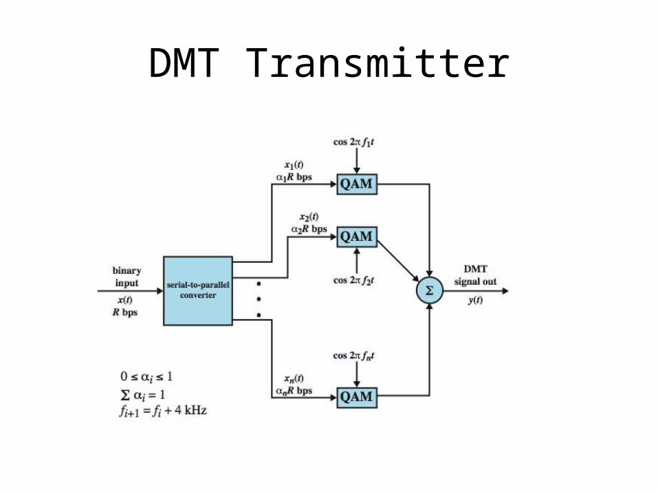
DMT Transmitter
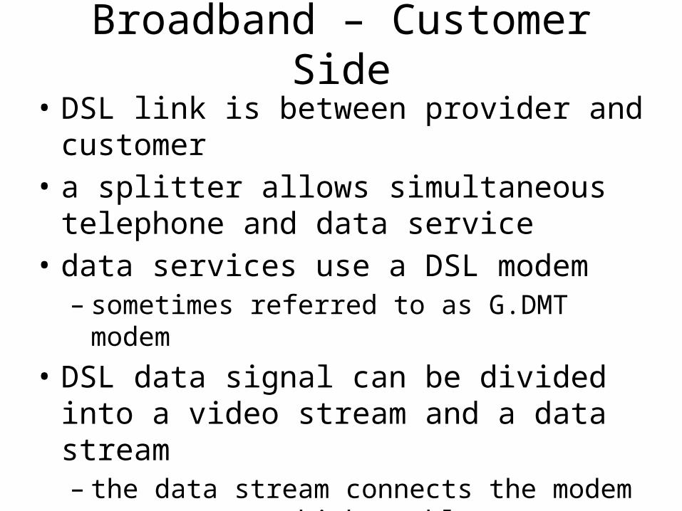
Broadband – Customer Side
• DSL link is between provider and customer• a splitter allows simultaneous telephone
and data service• data services use a DSL modem
– sometimes referred to as G.DMT modem
• DSL data signal can be divided into a video stream and a data stream– the data stream connects the modem to a
router which enables a customer to support a wireless local area network
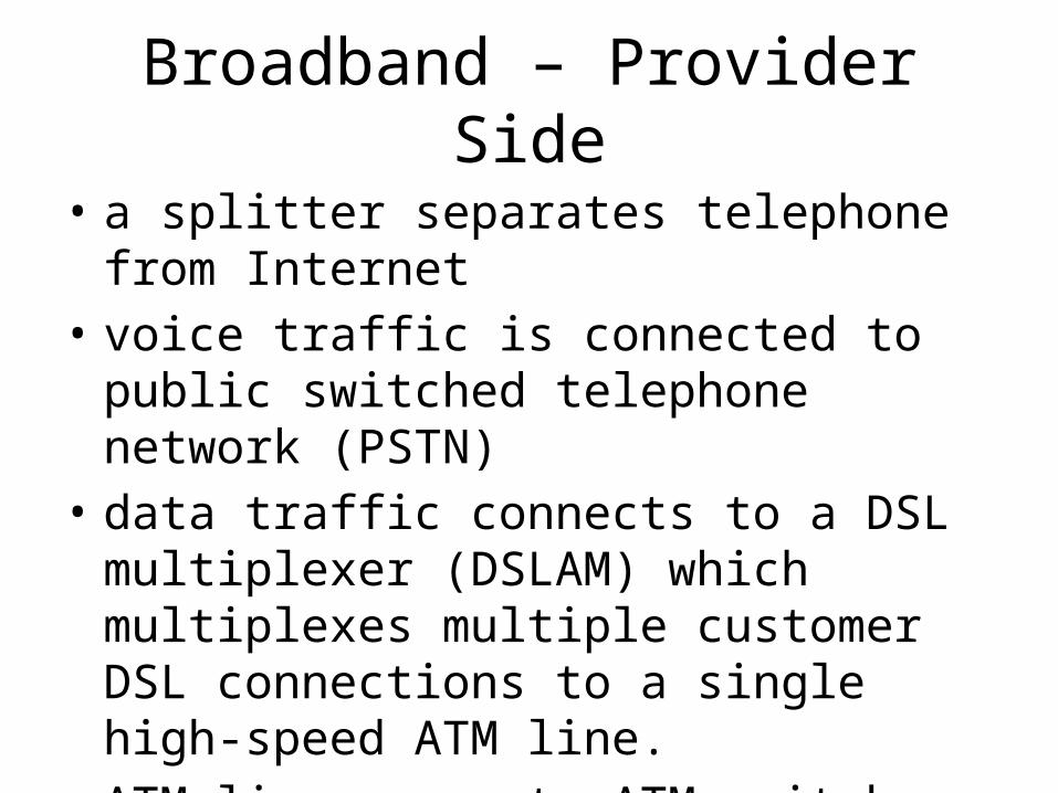
Broadband – Provider Side
• a splitter separates telephone from Internet • voice traffic is connected to public switched
telephone network (PSTN)• data traffic connects to a DSL multiplexer
(DSLAM) which multiplexes multiple customer DSL connections to a single high-speed ATM line.
• ATM line connects ATM switches to a router which provides entry to the Internet
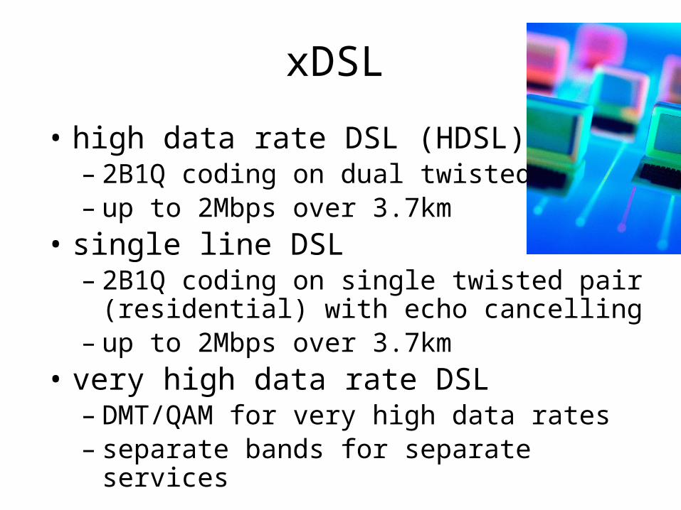
xDSL
• high data rate DSL (HDSL)– 2B1Q coding on dual twisted pairs– up to 2Mbps over 3.7km
• single line DSL– 2B1Q coding on single twisted pair
(residential) with echo cancelling– up to 2Mbps over 3.7km
• very high data rate DSL– DMT/QAM for very high data rates– separate bands for separate services
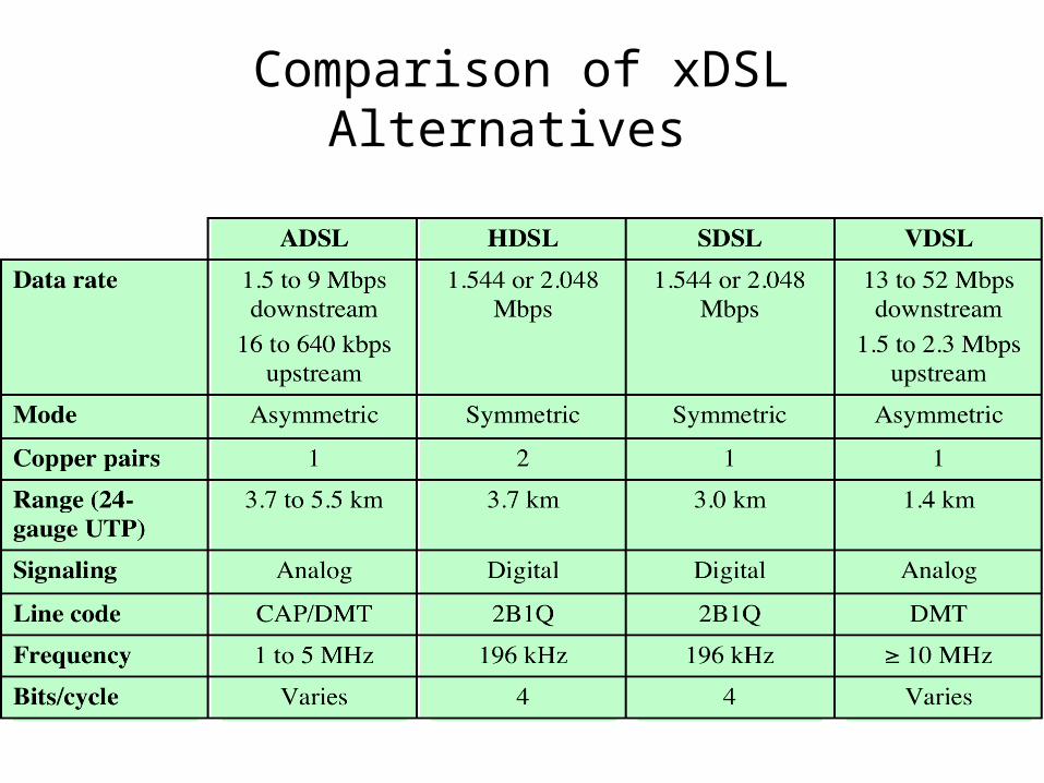
Comparison of xDSL Alternatives
Summary• multiplexing multiple channels on single link• FDM
– analog carrier systems– wavelength division multiplexing
• TDM– TDM link control– pulse stuffing
• statistical TDM• broadband• ADSL and xDSL


