MultiPrep™ Procedure TEM Wedge Preparation of an Integrated Circuit (IC) G.D. Liechty; E. Hirsch; C.A. Smith, Allied High Tech Products, Inc. February 2007 Overview The MultiPrep™ is an efficient tool for preparing materials for TEM observation in either wedge or plan-view format. Samples are reliably polished to electron transparency, often eliminating the need for ion milling. Consistent sample rotation, oscillation and load provide uniform material removal and eliminate artifacts that can be associated with manual polishing. The dial indicator measures the sample and allows the operator to monitor its thickness throughout the polishing process, decreasing preparation time by eliminating the guesswork associated with hand- held polishing tools. Only the sample makes contact with the abrasive during polishing, ensuring that the desired angle (wedge polishing) remains intact throughout the process. The wedge technique provides a large, electron-transparent area in one dimension, making it ideal for semiconductors, and it allows simultaneous preparation of multiple interfaces (i.e., thin films/superconductors). In this procedure, the polished (first) side of an IC (see cross-sectioning procedure) is mounted to a fixture with a Pyrex insert that has been polished parallel with the abrasive plane. The second side is thinned to remove bulk material. A wedge angle is then induced at 1 degree and the sample is final polished to electron transparency. The sample can then be ion milled or observed in the TEM. It is strongly recommended that the MultiPrep™ System manual be studied to ensure familiarity with the terms used to describe certain functions and components in this procedure. Consumable selection, machine settings and techniques used in this procedure were developed using the MultiPrep™ System in Allied’s applications laboratory.
Transcript
MultiPrep™ Procedure
TEM Wedge Preparation of an Integrated Circuit (IC) G.D. Liechty; E. Hirsch; C.A. Smith, Allied High Tech Products, Inc. February 2007
Overview
The MultiPrep™ is an efficient tool for preparing
materials for TEM observation in either wedge or plan-view format. Samples are reliably polished to
electron transparency, often eliminating the need for ion milling. Consistent sample rotation,
oscillation and load provide uniform material
removal and eliminate artifacts that can be associated with manual polishing. The dial
indicator measures the sample and allows the
operator to monitor its thickness throughout the
polishing process, decreasing preparation time by eliminating the guesswork associated with hand-
held polishing tools. Only the sample makes contact with the abrasive during polishing, ensuring
that the desired angle (wedge polishing) remains
intact throughout the process. The wedge technique provides a large, electron-transparent
area in one dimension, making it ideal for semiconductors, and it allows simultaneous
preparation of multiple interfaces (i.e., thin
films/superconductors).
In this procedure, the polished (first) side of an IC (see cross-sectioning procedure) is mounted to a
fixture with a Pyrex insert that has been polished
parallel with the abrasive plane. The second side is thinned to remove bulk material. A wedge angle is
then induced at 1 degree and the sample is final polished to electron transparency. The sample can
then be ion milled or observed in the TEM.
It is strongly recommended that the MultiPrep™
System manual be studied to ensure familiarity with the terms used to describe certain functions and
components in this procedure.
Consumable selection, machine settings and techniques used in this procedure were developed
using the MultiPrep™ System in Allied’s applications laboratory.
50-30000 DLF Storage/Blotter Book 200-20000 Aero-Duster Canned Air
Other:
Hot Plate w/ Temperature Readout (Dataplate PMC 720)
Microscope Slides Tweezers, Sharp End
Acetone Isopropyl Alcohol
Paper, 8 x 11 White
Filter Paper
3
Procedure
1. Place a microscope slide onto a hot plate set to 175° C.
2. Melt wax onto the slide, place the circuit side of the
polished sample into the wax (Photo 1) and remove the slide and sample to cool at room temperature.
3. Secure the slide into the saddle clamp and attach to the arm of the TechCut 4™ (see Photo 2). Rotate the slide in the fixture so the circuit geometry is aligned with the
edge of the blade. 4. Position the sample by adjusting the micrometer so the
blade is approximately 1,000 microns from the polished edge.
5. Section through the sample and through the glass cover slip but not through the microscope slide (see Photo 3).
Photo 1
Photo 2
Photo 3
6. Place the slide onto the hot plate. Once the wax is melted, remove the smaller sample and place it in a beaker of Acetone.
7. Swirl the sample thoroughly to remove the traces of wax.
8. Remove the sample from the Acetone and place it onto filter paper to absorb the Acetone for about 60 seconds.
9. Place the sample in a beaker of IPA (isopropyl alcohol) and swirl it for 20 to 30 seconds to remove the residual Acetone.
10. Remove the sample and place it onto filter paper to absorb the excess IPA for another 60 seconds. 11. With a cotton swab, clean the sample using a solution of Micro Organic Soap mixed with water (1:10).
12. Rinse the sample with water and dry using a clean air source such as an Aero-Duster.
13. Calibrate the MultiPrep™ System according to the procedures in the manual.
4
14. Secure a 9µm DLF to the platen and set the sample load to “full”.
15. Using the cam-lock adapter, attach the TEM/Pyrex paddle (see below) onto the MultiPrep™ configured as shown in Photo 10.
16. Lower the spindle with the spindle riser (if raised) and raise
the arm using the vertical adjustment knob so the Pyrex
does not touch the DLF. Zero the digital dial indicator by pressing the yellow button labeled “Zero”.
17. Activate platen rotation counterclockwise at 100 RPM. 18. Activate oscillation at speed 3 and set the range to about 1”
located at least 1” away from the center of the platen toward the edge.
19. Activate coolant and lower the paddle (using the vertical
adjustment knob) until the Pyrex makes contact and the digital dial indicator displays at least 75 microns. Be sure to
polish enough of the Pyrex so the entire surface is parallel
with the platen.
20. Repeat steps 14-19 using 3 µm DLF and polish the Pyrex for at least 3 minutes at 80 RPM.
Note: By grinding the bottom of the Pyrex on the abrasive surface used to thin the sample, a parallel reference is established so the sample may be thinned as close to parallel as possible. Only the adhesive used to secure
the sample to the Pyrex may interfere with accurate registration. If glued properly, the effects of the adhesive are negligible.
21. Raise the spindle with the spindle riser. Remove the paddle and clean the polished surface of the Pyrex with IPA and dry using clean air.
22. Mount the sample to the Pyrex using either wax or glue. There are advantages with each method and only with trial and error will it be possible to determine the better of the two.
Notes on Adhering the Sample to the Pyrex When attaching the sample to the Pyrex, it is very
important that no bubbles exist in the adhesive layer. If
they exist the sample will likely disintegrate when thinned due to lack of support.
When securing the sample to the Pyrex and the glue or
wax is in a liquefied state, be sure to apply adequate pressure to the backside of the sample to squeeze the
adhesive to force the bubbles out.
Observation through the back of the Pyrex will reveal if
bubbles are present.
Failure to clean the Pyrex and sample may enable bubbles
to form when residual acetone or IPA used to clean the surfaces turn from a liquid/solid to a gas and become
trapped.
#15-1013, TEM/Pyrex Paddle
Wax Glue
5
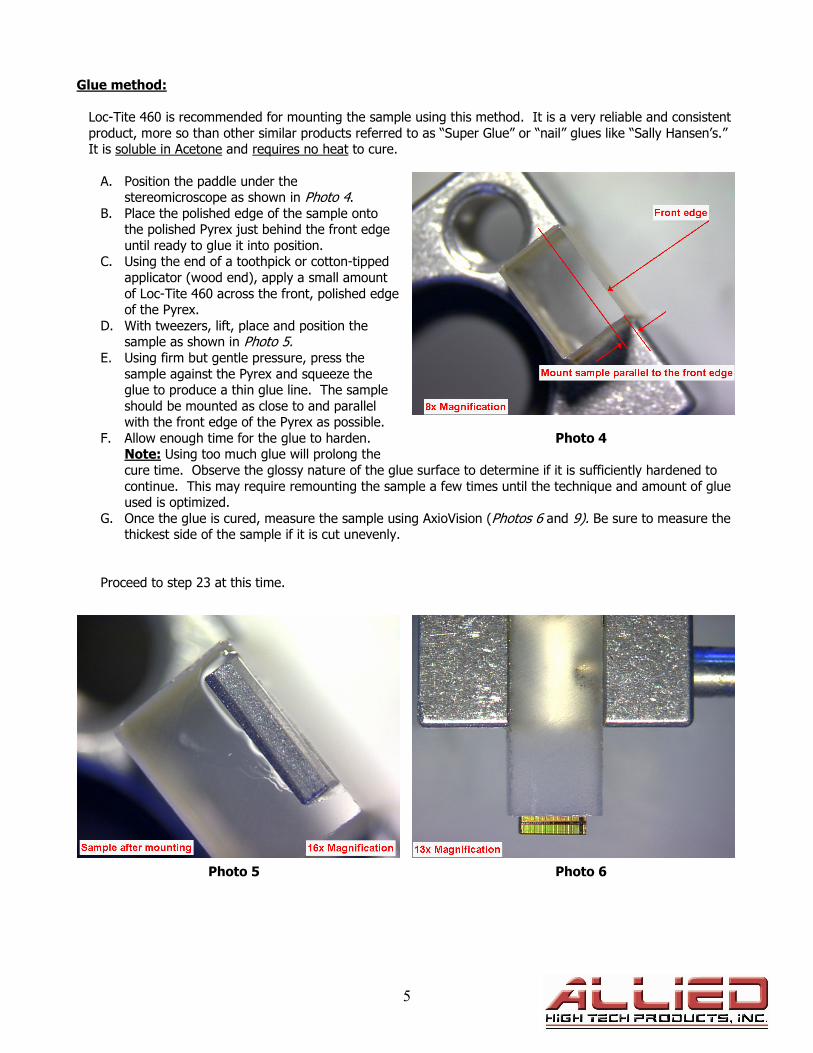
Glue method:
Loc-Tite 460 is recommended for mounting the sample using this method. It is a very reliable and consistent
product, more so than other similar products referred to as “Super Glue” or “nail” glues like “Sally Hansen’s.” It is soluble in Acetone and requires no heat to cure.
A. Position the paddle under the stereomicroscope as shown in Photo 4.
B. Place the polished edge of the sample onto the polished Pyrex just behind the front edge
until ready to glue it into position. C. Using the end of a toothpick or cotton-tipped
applicator (wood end), apply a small amount
of Loc-Tite 460 across the front, polished edge of the Pyrex.
D. With tweezers, lift, place and position the sample as shown in Photo 5.
E. Using firm but gentle pressure, press the
sample against the Pyrex and squeeze the glue to produce a thin glue line. The sample
should be mounted as close to and parallel with the front edge of the Pyrex as possible.
F. Allow enough time for the glue to harden. Photo 4 Note: Using too much glue will prolong the
cure time. Observe the glossy nature of the glue surface to determine if it is sufficiently hardened to
continue. This may require remounting the sample a few times until the technique and amount of glue used is optimized.
G. Once the glue is cured, measure the sample using AxioVision (Photos 6 and 9). Be sure to measure the thickest side of the sample if it is cut unevenly.
Proceed to step 23 at this time.
Photo 5 Photo 6
6
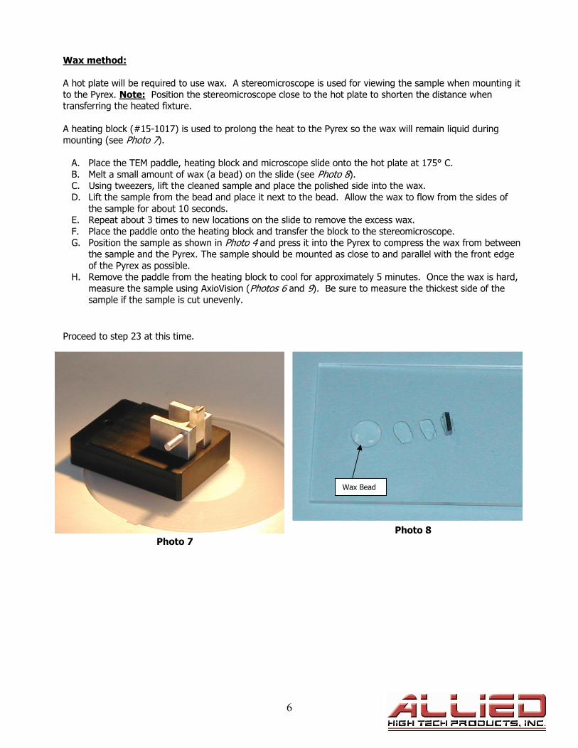
Wax method:
A hot plate will be required to use wax. A stereomicroscope is used for viewing the sample when mounting it
to the Pyrex. Note: Position the stereomicroscope close to the hot plate to shorten the distance when transferring the heated fixture.
A heating block (#15-1017) is used to prolong the heat to the Pyrex so the wax will remain liquid during mounting (see Photo 7).
A. Place the TEM paddle, heating block and microscope slide onto the hot plate at 175° C.
B. Melt a small amount of wax (a bead) on the slide (see Photo 8). C. Using tweezers, lift the cleaned sample and place the polished side into the wax. D. Lift the sample from the bead and place it next to the bead. Allow the wax to flow from the sides of
the sample for about 10 seconds. E. Repeat about 3 times to new locations on the slide to remove the excess wax.
F. Place the paddle onto the heating block and transfer the block to the stereomicroscope. G. Position the sample as shown in Photo 4 and press it into the Pyrex to compress the wax from between
the sample and the Pyrex. The sample should be mounted as close to and parallel with the front edge
of the Pyrex as possible. H. Remove the paddle from the heating block to cool for approximately 5 minutes. Once the wax is hard,
measure the sample using AxioVision (Photos 6 and 9). Be sure to measure the thickest side of the sample if the sample is cut unevenly.
Proceed to step 23 at this time.
Photo 8
Photo 7
Wax Bead
7
23. Place the paddle under the
stereomicroscope. With a razor blade, remove the
excess glue or wax from the glass cover slip where the
sample is mounted to the
Pyrex so that the sample may be observed in the
microscope for measurement purposes.
24. Secure a 15 µm DLF to the platen.
25. Raise the arm more than the
thickness of the sample using the vertical adjustment knob
so that when the spindle is lowered with the spindle riser
the sample does not touch
the DLF. 26. Attach the paddle onto the
cam-lock adapter (see Photo 10).
Photo 9
27. Position the sample between the edge and the center of the platen (see Photo 10). 28. Set load to 300 grams. 29. Lower the spindle riser and zero the dial indicator.
30. Using the vertical adjustment knob, lower the sample into the abrasive until the digital dial indicator displays 100 microns more than what needs to be removed. For example, if 800 microns is to be
removed, the dial should display “900” microns. Note: The objective is to stop so approximately 200
microns of the sample remains on the Pyrex using 15 µm DLF (see Photo 9). 31. Raise the sample using the spindle riser.
32. Activate platen rotation counterclockwise at 10 RPM. 33. Activate coolant and gently lower the sample onto the DLF using the spindle riser. Once contact is
made between the sample and the abrasive, zero the dial indicator. Increase platen speed to 75 RPM,
polish all but approximately 200 microns from the sample and raise the sample with the spindle
riser. 34. Clean and measure the sample. Note: It may be
necessary to increase the magnification to get a more accurate measurement. The polished edge
will now be parallel with the Pyrex.
35. Secure a 6 µm DLF to the platen. 36. Polish the sample until it is about 100 microns
thick. Repeat steps 29-32 except use 60 RPM. 37. Stop the platen, raise the sample from the platen
with the spindle riser and remove the sample for
measurement and inspection. 38. Secure a 3 µm DLF to the platen.
39. Polish the sample until it is about 30 microns thick. 40. Repeat steps 29-32 except use 40 RPM. Photo 10
41. Stop the platen, raise the sample from the platen with the spindle riser and remove the sample for measurement and inspection.
Approximately 200 microns
8
Note: The sample is measured either by focusing through the glass cover slip on the circuitry or on the top of the cover slip. Measuring through the cover slip may create difficulty in determining the actual edge due to
the reflection of light on the polished edge of the cover slip and the limited resolution. See Photos 11 and 12 to see the difference.
Photo 11 Photo 12
Note: The desired angle may vary from sample to sample. However, when polishing IC’s, a shallow angle is
normally used so that every level of metal can be thinned from top to bottom. Too steep of an angle will not
allow all the metals lines to be thinned entirely.
42. Using the vertical adjustment knob, raise the arm at least five (5) full rotations. Note: Because the angle adjustment will drive the front edge of the Pyrex closer to the platen, the arm of the MultiPrep™
must be raised.
43. Adjust the front “left” micrometer to the desired “wedge” angle by rotating it clockwise. Fifty vertical lines equal one full revolution and 1°.
44. Secure a 0.5 µm DLF to the platen. 45. Attach the paddle, lower the sample with the
spindle riser and zero the dial indicator.
46. Use the vertical adjustment knob and lower the sample into the abrasive until the digital
dial indicator displays about 80 to 100 microns.
47. Raise the sample using the spindle riser. 48. Activate platen rotation clockwise at 10 RPM.
49. Activate the coolant and gently lower the
sample onto the DLF using the spindle riser. Allow the sample to make contact with the
DLF for one-half revolution, then lift the sample with the spindle riser.
50. Inspect the sample to determine if a facet
angle is present. If parallel as in Photo 15, continue to step 55.
Photo 13
Note: If the facet is not parallel with the circuit line as shown in Photo 13, the wax or glue line is either uneven or the sample is not mounted parallel with the front edge of the Pyrex.
51. Using AxioVision, measure the facet angle as shown in Photo 13. Using the value of the angle as measured, look up the necessary correction value in Graph #1.
9
52. Based on the sample measured in Photo 13, an adjustment to the right-rear micrometer will correct the
facet angle on the sample used in this illustration, so it is parallel with the circuit line. The graph indicates the micrometer head requires adjustment by 0.05 degrees (2.5 ticks, see Photo 14).
Photo 14 Graph 1
Note: Graph 1 applies to samples angled at 1°. For other angles, multiply the wedge angle by the top view angle and multiply by 0.01.
Example: Top View Angle 2°
Wedge Angle 4° x
Equals 8 Multiply x 0.01 = 0.08
Represents the number if increments the micrometer head needs to be adjusted.
53. After the adjustment is made, polish the sample for another one-half
rotation. 54. Raise the sample with the spindle
riser and inspect it to verify accuracy of angle adjustment (see Photo 15).
55. When the facet is parallel, measure
the sample thickness before proceeding with the final thinning
(see Photo 16). 56. Attach and lower the paddle using
the spindle riser and zero the dial
indicator. 57. At 10 RPM, polish all but 10 microns
from the sample and remove it to inspect under transmitted light (see
Photo 17).
Photo 15
0.02°
TEM Wedge Left to Right
Correction Angle
y = 0.0149x
00.020.040.060.080.10.120.140.160.180.20.220.24
0 2 4 6 8 10 12 14 16
Top View Angle (T)
Left/Right Correction
Angle (LR)
10
Note: While thinning the sample with 0.5 µm DLF, eventually the front edge will thin to a point where it will
no longer be possible to measure the thickness. The color of the sample will then be used to determine thickness. However, the digital dial indicator may still be used to monitor the polishing rate.
58. Once the sample is similar to that shown in Photo 16, return to the 0.5 µm DLF and remove 2 microns
at a time until the glass cover slip begins to recede to an overall thickness between 50 and 75 microns
(cross-section thickness, see Photo 17). 59. Apply a Red Final C polishing cloth to a separate platen and place it onto the TechPrep™.
60. Remove the cam-lock adapter and attach the paddle on the underside of the micro-hub.
61. Set the limit sensors so the sample rotates to the approximate positions indicated in Figure 1.
62. Activate coolant and saturate the cloth. 63. Activate platen rotation clockwise at 150 RPM.
64. Activate “Limit” rotation at speed 1 (slowest). 65. Position the water flow at the edge of the
platen to reduce colloidal silica splash on the
bowl. 66. Apply 0.05 µm colloidal silica to the cloth.
67. With the vertical adjustment knob, lower the sample into the cloth until a trail is observed
and the dial indicator displays between 20 and 30 microns, ensuring sufficient sample contact
with the cloth. It may be necessary to add
more colloidal silica to the cloth while lowering the sample so the trail can be
observed. 68. Polish the sample in 1-minute intervals.
Between intervals, clean and inspect the
sample condition and progress. At the point where the glass recedes and approaches the
circuitry, fringes will appear in the silicon.
Figure 1
Photo 17
Platen
Photo 16
11
At this point the sample can be thinned in the ion mill for a short period of time (under 5 minutes) to clean and remove artifacts. Continuing to polish the sample thinner can be more risky than ion milling to its final
thickness. As operator skill level and familiarity with the MultiPrep™ increase, the sample can eventually be put into the TEM without ion milling.
200X Magnification, Transmitted Light
500X Magnification, Transmitted Light
12
Equipment Photo Page
Stemi DV-4 TechCut 4 MultiPrep System AxioVision 4™ Imaging/Capture Software