809 Multipurpose Packer System Gonzalo Pulido, HydroQual, Inc. ([email protected]) Thomas P. Ballestero, University of New Hampshire ([email protected]) and Nancy E. Kinner, University of New Hampshire ([email protected]) Abstract The Multipurpose Packer System (MPS) is a discrete-interval isolation system for the sampling and hydraulic assessment of wells completed in heterogeneous formations. The MPS consists of inflatable packers connected by threaded aluminum pipe, to isolate discrete intervals in the well. The packer to pipe couplings have sampling ports with miniature fittings. Pressure transducers and small diameter tubing are connected to the fittings and run through the aluminum pipe to a control board located at the wellhead. Data on hydraulic head, water sampling, and hydraulic testing can be collected for each isolated interval. An MPS prototype was successfully designed, fabricated, and installed in a 6” diameter, 200’ deep well completed in a fractured bedrock formation contaminated with chlorinated solvents. The MPS isolated the intervals and was used successfully for hydraulic testing and water sampling. The MPS helps to minimize water quality biases. Additional research is being conducted to optimize the MPS design and its range of applications. Introduction Even though assuming homogeneity facilitates assessment of hydrogeologic phenomena, most hydrogeological environments are heterogeneous with respect to groundwater flow and transport processes, requiring more sophisticated instrumentation and methods of analysis. In fractured bedrock formations, each fracture zone can exhibit a different hydraulic head (Johnson et al., 2001) and even in homogeneous formations, contaminant plumes are inherently heterogeneous (Smith et al., 1987). Initially, clusters of monitoring wells were used for monitoring of heterogeneous hydrogeological sites. The main disadvantages of clusters are their comparative high costs, extensive site disturbance, and purge water volumes (Robbins and Martin-Hayden, 1991). Nested monitoring wells address these limitations, but exhibit interval-sealing difficulties and concerns (US EPA, 1986). Today, several patented instruments are available for discrete zone isolation and sampling. The FLUTe TM is a flexible-liner system that effectively seals and allows pressure measurements and water sampling from discrete intervals (Keller, 2002). The MP TM is a modular multiport system that employs a single, closed access tube with valved ports. Thus, different levels of a borehole are isolated within a single well casing (Hartten and Genau, 1995). The modular Waterloo Multilevel Groundwater Monitoring System TM (WMS) includes a closed casing containing small diameter tubes, that connect each isolated monitoring port to the surface allowing groundwater sampling and hydraulic measurements (Cherry and Johnson, 1982). The Continuous Multichannel Tubing (CMT TM ) uses a custom-extruded flexible tubing to monitor as many as seven discrete zones (Einarson and Cherry, 2002). All the previously described systems, isolate discrete vertical zones and allow monitoring water levels and water quality in each zone. Depending on the specific project objectives, it is desirable to additionally be able to conduct pumping tests and slug tests at each isolated interval, as well as injecting and detecting tracers. In this way, the interconnectivity between isolated intervals could be assessed. These are the distinctive features provided by the Multipurpose Packer System (MPS) reported in this paper. An additional advantage of the MPS is that all its components are off-the-shelf items. Materials and Methods As with other multi-level devices, the MPS design is tailored to each well, based on well specifications and project objectives. A MPS prototype was designed and installed in well BBC5, drilled in a crystalline fractured bedrock formation as part of a project carried out by the Bedrock Bioremediation Center (BBC) at a Superfund site located in Portsmouth, NH (Pulido, 2003). A removable MPS was designed to isolate five fracture zones (I1
Abstract The Multipurpose Packer System (MPS) is a discrete-interval isolation system for the sampling and hydraulic assessment of wells completed in heterogeneous formations. The MPS consists of inflatable packers connected by threaded aluminum pipe, to isolate discrete intervals in the well. The packer to pipe couplings have sampling ports with miniature fittings. Pressure transducers and small diameter tubing are connected to the fittings and run through the aluminum pipe to a control board located at the wellhead. Data on hydraulic head, water sampling, and hydraulic testing can be collected for each isolated interval. An MPS prototype was successfully designed, fabricated, and installed in a 6” diameter, 200’ deep well completed in a fractured bedrock formation contaminated with chlorinated solvents. The MPS isolated the intervals and was used successfully for hydraulic testing and water sampling. The MPS helps to minimize water quality biases. Additional research is being conducted to optimize the MPS design and its range of applications. Introduction
Even though assuming homogeneity facilitates assessment of hydrogeologic phenomena, most hydrogeological environments are heterogeneous with respect to groundwater flow and transport processes, requiring more sophisticated instrumentation and methods of analysis. In fractured bedrock formations, each fracture zone can exhibit a different hydraulic head (Johnson et al., 2001) and even in homogeneous formations, contaminant plumes are inherently heterogeneous (Smith et al., 1987). Initially, clusters of monitoring wells were used for monitoring of heterogeneous hydrogeological sites. The main disadvantages of clusters are their comparative high costs, extensive site disturbance, and purge water volumes (Robbins and Martin-Hayden, 1991). Nested monitoring wells address these limitations, but exhibit interval-sealing difficulties and concerns (US EPA, 1986). Today, several patented instruments are available for discrete zone isolation and sampling. The FLUTeTM is a flexible-liner system that effectively seals and allows pressure measurements and water sampling from discrete intervals (Keller, 2002). The MPTM is a modular multiport system that employs a single, closed access tube with valved ports. Thus, different levels of a borehole are isolated within a single well casing (Hartten and Genau, 1995). The modular Waterloo Multilevel Groundwater Monitoring SystemTM (WMS) includes a closed casing containing small diameter tubes, that connect each isolated monitoring port to the surface allowing groundwater sampling and hydraulic measurements (Cherry and Johnson, 1982). The Continuous Multichannel Tubing (CMTTM) uses a custom-extruded flexible tubing to monitor as many as seven discrete zones (Einarson and Cherry, 2002). All the previously described systems, isolate discrete vertical zones and allow monitoring water levels and water quality in each zone. Depending on the specific project objectives, it is desirable to additionally be able to conduct pumping tests and slug tests at each isolated interval, as well as injecting and detecting tracers. In this way, the interconnectivity between isolated intervals could be assessed. These are the distinctive features provided by the Multipurpose Packer System (MPS) reported in this paper. An additional advantage of the MPS is that all its components are off-the-shelf items. Materials and Methods As with other multi-level devices, the MPS design is tailored to each well, based on well specifications and project objectives. A MPS prototype was designed and installed in well BBC5, drilled in a crystalline fractured bedrock formation as part of a project carried out by the Bedrock Bioremediation Center (BBC) at a Superfund site located in Portsmouth, NH (Pulido, 2003). A removable MPS was designed to isolate five fracture zones (I1
810
to I5); two of these (I2, I4) were identified as high hydraulic conductivity fracture zones, during previous straddle-packer hydraulic testing and borehole geophysics. The MPS prototype used inflatable packers (TAMTM; Houston, TX) connected to aluminum pipe to isolate discrete intervals. The packer to pipe couplings were fabricated with ports containing miniature fittings (Beswick Engineering; Greenland, NH) to allow hydraulic head measurement, water quality sampling, hydraulic testing and tracer injection/sampling at each isolated interval. Pressure transducers (PDCR 1830 DruckTM; New Fairfield, CT) and small diameter tubing (Freelin-WadeTM; McMinnville, OR) were connected to the fittings and passed through the pipes to an aboveground control board. The inflatable packers (P) were connected to 4” inside diameter (ID) aluminum pipe using stainless steel couplings. The deepest (P3, P4) and upper (P1, P2) packers were 2” ID and 4” ID, respectively. The larger packers were needed to accommodate all of the MPS tubing bundles to pass through them. An injection, purging, and slug line (IPS), provided the MPS with the capability to inject a tracer, purge water, and perform slug tests. Similar to other MPS lines, it was 1/8” ID translucent polyurethane tubing. For each interval, the IPS line went from the ground surface, inside the aluminum pipe, down to the injection coupling (IC), located at the bottom coupling for each well interval. The IC had a ¼” thread to internally attach a stainless steel ¼” male elbow to a 1/8” tubing barb. Threaded tubing clamps were used to secure the IPS lines to the 1/8” barb fittings. The water sampling system provides the MPS with the capability to extract groundwater from each isolated interval. The system consisted of two lengths of 1/8” tubing: a pressurization line (color-coded orange), and a discharge line (color-coded blue). At the top of the designated isolated interval, the two lines were connected to each other with a stainless steel 1/8” barbed “T” fitting. The third branch of the “T” was connected to a stainless steel 1/8” check valve. The valve was connected to the water sampling coupling (WSC) by an elbow fitting. The WSC was the upper coupling of each isolated interval. This coupling had an internally installed ¼” elbow to thread to a pressure transducer (range (0 – 200) psi, accuracy 0.04% Full Scale). Under normal conditions, the water sampling lines were full of water up to the hydraulic head elevation of the isolated interval. When gas (e.g., nitrogen) was applied to the pressurization line, the water volume contained in the water sampling lines was pushed out of the well through the discharge line. The check valve prevented flow back into the formation from the isolated interval. When gas pressure was released, the check valve allowed water to flow from the formation’s isolated well interval into the water sampling lines until they were refilled. By repeating this process, the desired volume of water could be collected from the interval. Each interval communicated with the surface by a bundle (B) consisting of a transducer cable, IPS, and water sampling lines. B1, B2, and B3 additionally contained IPS lines of diameters 1”, ¼”, and ½” that were connected to WSC1, WSC2, and WSC3, respectively, to study some of the MPS slug test features. The 4” MPS bottom cap (WSC5) contained the IPS line port for I5. IC1 was located immediately above P1; WSC1 was located 10’ above IC1. A drain bundle (a water sampling line with its check valve at the very bottom, inside the MPS casing) was provided to evacuate any water volume that could leak into the MPS casing. Thus, the leakage rate into the 4” pipe can be evaluated to decide whether the MPS must be removed and reinstalled to eliminate the leaking, or the leaking is low enough to not to be considered a contaminants migration issue, specially taking into account the two levels of protection against that, offered by the MPS design. That means, even if some contaminant enters the MPS casing by some coupling, it is necessary that exists a second leaking between the casing and the water sampling line to get the undesired contaminant migration effect. Above the ground surface, IPS and water sampling lines were connected to a control board. The pressure transducers were wired to a datalogger (CR10X Campbell Scientific; Logan, UT) for pressure data storage. The MPS was inflated with nitrogen by a single 1/8” ID clear polyurethane tubing that connected all packers. All tubing (sampling, testing, packer inflation) were provided with quick-disconnect brass valves, and normally capped to avoid interference signals between lines at the same interval. The overall cost of the BBC5 MPS prototype components was ~ $20,000.00 (US dollars, 2002) (including $6,000 for the transducers and datalogger).
811
Figure 1. MPS Schematic and terminology
812
Figure 1. (Continuation)
813
MPS Prototype Constructive Procedure After decontamination of each MPS component, 200’ of sheet plastic, was unrolled on the ground starting at the BBC5 casing. The MPS bundles were assembled on this. P4 was passed though B5 and the drain bundle, and these bundles were connected to WSC5. Teflon tape was applied on every threaded fitting to minimize leaks. After threading and tightening WSC5 to P4, this MPS section was inserted into the well and held in place at the top of the casing (TOC) by a pipe clamp. An aluminum tripod-cable-winch system was used to raise each new section of pipe or packer to be added to the MPS section already in the well. A 200 psi pressurization test was conducted each time a new packer was added, to test the integrity of the system. When the MPS was fully installed in the well, the bundles were run from the top of casing through a 4” corrugated plastic hose, and directed to a shed to provide for year round protection. Inside the shed, pressure transducers cables were wired to the datalogger and the tubing bundles were connected and organized on a control board. MPS Performance Tests The packers in the MPS prototype were inflated by applying 150 psi. Before inflation, the BBC5 static water level (2.0’ +/- 0.01’) was measured with a water level sounder and the all transducer data logging was initiated. The actual top of casing-referenced depths for each WSC were calculated by adding the static water level to each of the stabilized pre-packer inflation pressure transducer readings (95.99’, 112.17’, 121.37’, 141.55’, and 163.09’ below top of casing, for WSC1 through WSC5, respectively). Therefore, the packer inflation pressure (150 psi total for all packers) above hydrostatic pressure at the bottom of the MPS was ~80 psi.
Inflation and Sealing Tests Inflation system integrity was confirmed after the MPS packers held the applied inflation pressure for two days. A sealing test was then conducted to determine the minimum inflation pressure required to prevent any hydraulic interconnection (short circuiting) between intervals. Experience with similar inflatable packers for hydraulic tests suggested packer inflation pressures of ~175 psi pressure at the nitrogen tank regulator gauge (89 psi above hydrostatic pressure), was a safe inflation pressure to seal between intervals down to 200’ depth (Pulido, 2003). For the packer sealing experiment, the MPS was initially pressurized to 175 psi (gauge) that was then reduced in 25 psi steps until deflation. In each step, first I4 was pressurized with 70 psi (equivalent to 161.0’ of water column) through its IPS line (161.5’ depth, top of casing) and then this pressure was released. Pressure in all intervals was recorded. Any I3 and I5 pressure responses to the I4 pressure signal were assumed to be a result of poor packer seals at the borehole wall. The 175, and 150 psi tests displayed good seals (Figure 2). Slight disturbances were recorded at I3 and I5 when the packer inflation pressure was 125 psi. Significant pressure variations were detected at I3 for the packer inflation pressure of 100 psi. At 75 psi (zero pressure relative to hydrostatic conditions at the bottom of the MPS), the packers deflated and all intervals were hydraulically communicating. As a result, 150 psi (80 psi relative to MPS bottom hydrostatic pressure) was selected as the minimum safe inflation pressure for the MPS.
814
110
120
130
140
150
160
Packer Inflation Pressure [ psi ]
I4 P
ress
ure
[ ft]
Pressure Applied to I4 1/8" ST tubing
I3an
d I5
Pre
ssur
e va
riatio
n fro
m b
asel
ine
[ft]
I4 I3 I570 707070
175 15075100125150
20
0
-10
-20
10
Figure 2. Results of inflation and packer sealing tests. 05/12/03. The MPS minimum safe inflation pressure was determined to be 150 psi. Slug Tests The BBC5 MPS prototype was designed to conduct slug test research related to: initial slug size and duration, nonlinear effects of the slug test tubing, and slug test tubing diameter influence on field data and analyses (Chirlin, 1990). Most slug test settings reported in the literature measure the drawdown (H) by monitoring the free surface water level variation at the top of the slug test casing (Butler, 1998). When nonlinear phenomena exist, the formation water pressure is substantially different than the top of casing water level because of turbulent flow into the slug test casing (McElwee and Zenner, 1998). The MPS used five, high reading frequency transducers, located directly at each isolated interval, in a port different than the IPS port, where the slug test pulse entered the formation. Hence, the influence of slug test magnitude and duration could be assessed because the transducer readings were not affected by the local flow effects in the injection line. Additional IPS lines were employed to determine the minimum IPS line diameter to obtain useful slug test results for quantitative analyses. The I2 to I5 MPS pressure transducers were connected to their respective WSC, located at the top of each interval; the I1 pressure transducer was located just above P1. Pressure transducers were set to record 8 pressure readings per second during slug tests. For I2, I3, and I4, the 1/8” IPS line was connected to the IC, located at the bottom of each respective well interval. The I1 IPS line was connected to IC1, located 10’ below WSC1. I1, I2, and I3 contained additional IPS lines (1”, ½”, and ¼” ID respectively) connected to WSC1, WSC2, and WSC3 by ports located opposite to the transducer ports (Figure 1). Slug tests at each isolated interval were conducted by first pressurizing the respective IPS line. When the pressure at the interval stabilized back to the original ambient value, a rising head slug test was produced by releasing the pressure from the IPS line. Rising slug test signals were generated at isolated intervals I2, I3, I4, and I5, by individually and independently applying 20 psi (equivalent to a water column Happlied = 46’) to their respective 1/8” IPS lines. Additional slug tests at I2 and I3 were conducted by applying the same 20 psi slugs to the ½” and ¼” IPS lines (Figure 3). I1 was not included in this experiment because it did not have a top packer. If nitrogen had been applied to IPS1, it would have escaped to the atmosphere, bubbling through the well casing – MPS annulus.
815
All slug test initial drawdowns (Ho) were one or two orders of magnitude less than Happlied (46’) (Figure 3). This effect was primarily due to the small IPS line diameters. For a given Happlied, the volume of water effectively removed from the isolated interval during a slug test decreased with the square of the IPS line diameter (0.75, 0.19, and 0.04 ft3 for the ½”, ¼”, and 1/8” IPS diameters, respectively). The effective Ho was proportional to that volume divided by the area of the annular space between the 4” aluminum pipe and the 6” well bore wall. Effectively, the observed Ho was less than 10’ for ¼” and ½” IPS, and less than 1’ for 1/8” IPS.
Time [minutes]
I2,I3
, I4,
and
I5 p
ress
ure
varia
tion
from
bas
elin
e [ft
] (1/
8" IP
S li
nes)
I2 a
nd I3
pre
ssur
e va
riatio
n fro
m b
asel
ine
[ft] (
1/2"
, and
1/4
" IP
S li
nes)
I2
I4
I2 (1/2")
I3 (1/4")
I3
I5
0
202.0
1.5
1.0
0.5
0.0302010
5
10
15
0
Ho
Figure 3. Slug test signals in the MPS intervals for various IPS diameters. All tests were initiated by applying 20 psi (Happlied = 46’) to the respective IPS line. For slug tests conducted with a given Happlied and IPS diameter, the effective Ho decreased when the isolated interval permeability increased (Figure 3). This can be explained by taking into account that to initiate a slug test at each interval, the IPS was depressurized; it took a finite time to release the nitrogen from each IPS line. During this time, a larger groundwater volume has reentered to the more permeable intervals (and their associated IPS lines). The effective slug test Ho depended on the IPS water level immediately after completion of nitrogen expulsion. Thus, Ho was larger for less permeable intervals. This was confirmed by the observed one order of magnitude lower Ho for I2 and I4 (high permeability), compared with I3, I5 Ho (low permeability) for the same IPS diameter.
Water Sampling
816
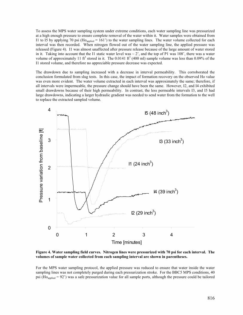
To assess the MPS water sampling system under extreme conditions, each water sampling line was pressurized at a high enough pressure to ensure complete removal of the water within it. Water samples were obtained from I1 to I5 by applying 70 psi (Hoapplied = 161’) to the water sampling lines. The water volume collected for each interval was then recorded. When nitrogen flowed out of the water sampling line, the applied pressure was released (Figure 4). I1 was almost unaffected after pressure release because of the large amount of water stored in it. Taking into account that the I1 static water level was ~ 2’, and the top of P1 was 108’, there was a water volume of approximately 11 ft3 stored in it. The 0.0141 ft3 (400 ml) sample volume was less than 0.09% of the I1 stored volume, and therefore no appreciable pressure decrease was expected. The drawdown due to sampling increased with a decrease in interval permeability. This corroborated the conclusion formulated from slug tests. In this case, the impact of formation recovery on the observed Ho value was even more evident. The water volume extracted in each interval was approximately the same; therefore, if all intervals were impermeable, the pressure change should have been the same. However, I2, and I4 exhibited small drawdowns because of their high permeability. In contrast, the less permeable intervals I3, and I5 had large drawdowns, indicating a larger hydraulic gradient was needed to send water from the formation to the well to replace the extracted sampled volume.
Time [minutes]
Pre
ssur
e va
riatio
n fro
m b
asel
ine
[ft]
0
2
1
04321
4
3
I4 (39 inch3)
I1 (24 inch3)
I3 (33 inch3)
I5 (48 inch3)
I2 (29 inch3)
Figure 4. Water sampling field curves. Nitrogen lines were pressurized with 70 psi for each interval. The volumes of sample water collected from each sampling interval are shown in parentheses. For the MPS water sampling protocol, the applied pressure was reduced to ensure that water inside the water sampling lines was not completely purged during each pressurization stroke. For the BBC5 MPS conditions, 40 psi (Hoapplied = 92’) was a safe pressurization value for all sample ports, although the pressure could be tailored
817
for each interval. Subsequent tests indicated that pressurizing with 40 psi for one minute, and releasing it for another minute, produced a 7.32 inch3 (120 ml) pumping stroke for all intervals. Fracture Characterization The water pressures at each interval isolated by the MPS were continuously monitored for seven months by recording pressure at all five intervals with a frequency of one reading/minute. Unlike open boreholes, the environmental piezometric fluctuations recorded by the MPS correlated with ocean tides along the nearby shores located approximately 10000 ft from the study site(Figure 5). I1 and I4 followed similar environmental trends, significantly larger than I2, I3, and I5 signals, and correlated with ocean water levels. This may indicate that the fracture zones intersected by these intervals extend to a larger scale than those fractures intersected by I2, I3, or I5.
0 6 12 18 24
Time [ hours ]
MPS i
nterva
ls pres
sure
varia
tion [
ft]
0
2
4
6
8
10
12
Ocea
n Wate
r Lev
el [ft]
I1I5
I5
I4
I4
I3
I2I1
0.0
1.0
0.8
0.6
0.4
0.2 OceanWaterLevel
Figure 5. MPS Environmental pressure trends and ocean tides recorded in New Castle, NH (NOOA, 2003). There was no sudden barometric pressure change, precipitation, or activity at the site during this period. Vertical gradients Pressure readings for each MPS interval under static conditions were used to study vertical gradients in BBC5 (Figure 6). Before the first MPS inflation, BBC5 was an open borehole, which “short-circuited” all intersected fracture zones until a well bore equilibrium was achieved, resulting in an apparent static water depth of 2.0’ below top of casing. Eight hours after packer inflation, pressures stabilized at all intervals. I1 stabilized to a smaller depth (higher piezometric level) indicating that it was recharging the other intervals before MPS inflation (downward vertical flow). Very small vertical gradients existed between I2, I3, I4, and I5.
818
90
110
130
150
1701.5 2.0 2.5 3.0 3.5
Static Water Depth [ft below TOC]
Dep
th [f
t TO
C]
04/08/03 (before first inflation) 04/08/03 (after first inflation)04/13/03 (inflated, midnight) 04/13/03 (inflated, noon)05/12/03 (before deflation) 05/12/03( deflated)
I1
I5
I4
I3
I2
Figure 6. Vertical hydraulic gradients in five BBC5 intervals isolated with the MPS.
BBC5 vertical gradients were time dependent. For example, six days after packer inflation, downward gradients I3-I4-I5, and I1-I2 were detected at midnight. A different pattern was observed at noon: I1 and I4 increased their static water depth, but I2, I3, and I5 exhibited little change. This generated an upward gradient I4-I5, and an almost zero gradient I2-I3. The MPS was deflated after one month in order to conduct the previously described inflation and sealing tests (Figure 2). Before deflation, I3 had a static water depth 1’ smaller than any other interval resulting in gradients of: I1-I3 upward, and I3-I5 downward. 30 minutes after MPS deflation, when pressure signals stabilized, gradient patterns persisted, but the I3 static water depth stabilized closer to the level of the others. Taking into account that I3 is a low hydraulic conductivity interval, this indicated that I3 was recharging the other intervals. Well BBC5 exhibited vertical water flow 30 minutes after the MPS deflation indicating short-circuiting within the well bore. Figure 6 data series “05/12/03 (deflated)” corresponds to the time immediately before the large positive peak at the right hand side of Figure 2; after that, the MPS packers were reinflated. Figure 2 suggests that at this time, each interval had nearly recovered to its own static conditions; nevertheless, Figure 6 indicates that there were actually vertical flows at this time, from I3 to the other intervals.
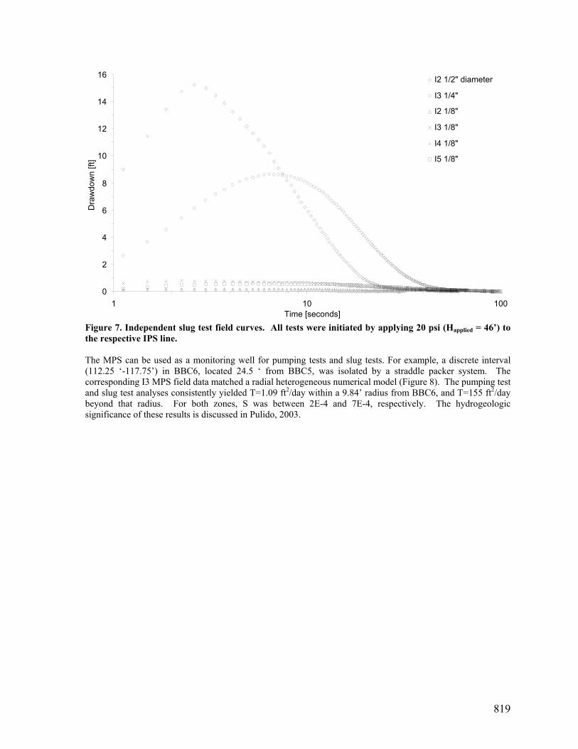
Hydraulic Parameter Estimation Extending the previous discussion about the impact of the slug test tubing diameter on slug test signals, the apparently instantaneous Ho duration for most IPS tested diameters (Figure 3), lose that character when plotted on a log time scale (Figure 7). The 1/8” IPS generated Ho < 0.02Happlied, and yielded noisy slug test signals unusable for quantitative analyses. The ¼” IPS line generated Ho = 0.15 Happlied, exhibiting a good quality signal but a non-instantaneous Ho duration (which prevented the accurate determination of the actual Ho magnitude). The ½” IPS line generated Ho = 0.33 Happlied with a near instantaneous Ho duration, enabling performance and analysis of slug tests with Ho<45’. As a result, the minimum recommended IPS line diameter is ½”.
819
0
2
4
6
8
10
12
14
16
1 10 100Time [seconds]
Dra
wdo
wn
[ft]
I2 1/2" diameter
I3 1/4"
I2 1/8"
I3 1/8"
I4 1/8"
I5 1/8"
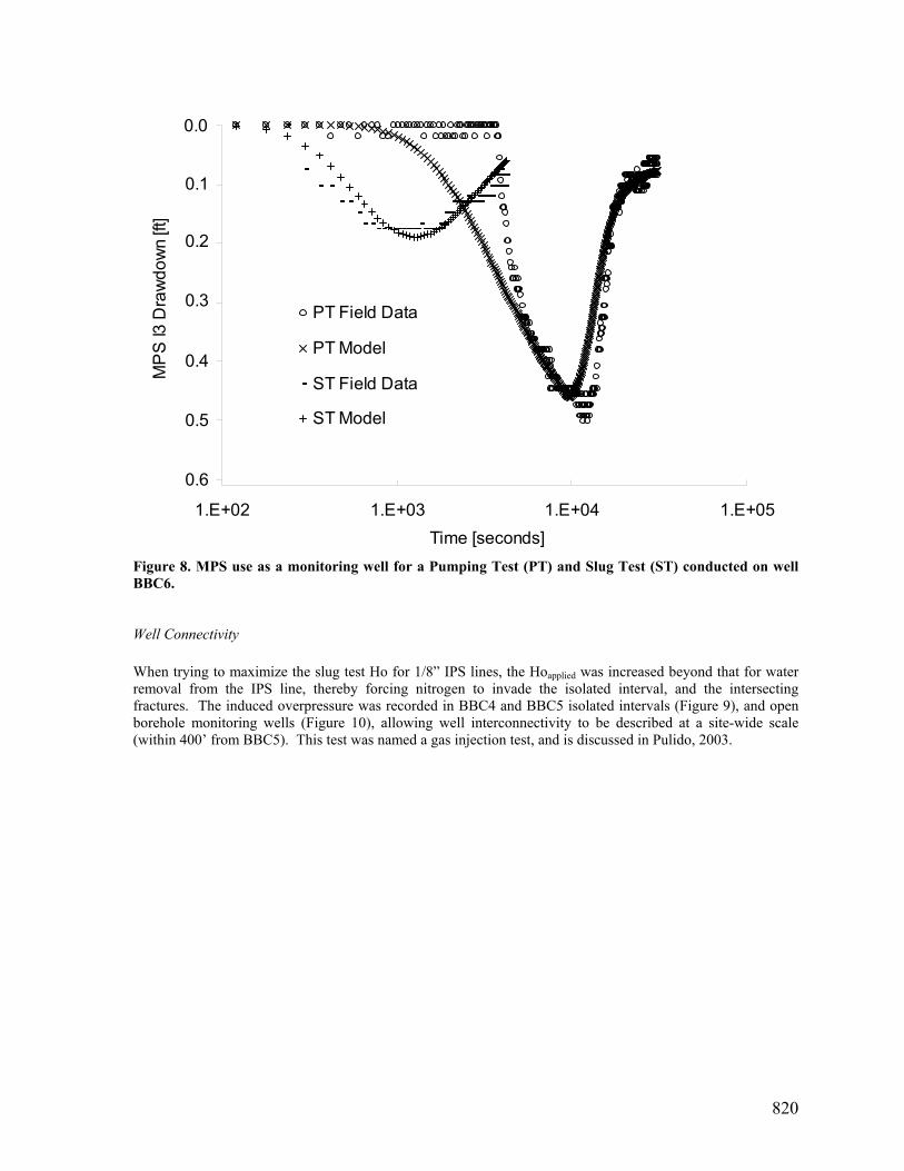
Figure 7. Independent slug test field curves. All tests were initiated by applying 20 psi (Happlied = 46’) to the respective IPS line. The MPS can be used as a monitoring well for pumping tests and slug tests. For example, a discrete interval (112.25 ‘-117.75’) in BBC6, located 24.5 ‘ from BBC5, was isolated by a straddle packer system. The corresponding I3 MPS field data matched a radial heterogeneous numerical model (Figure 8). The pumping test and slug test analyses consistently yielded T=1.09 ft2/day within a 9.84’ radius from BBC6, and T=155 ft2/day beyond that radius. For both zones, S was between 2E-4 and 7E-4, respectively. The hydrogeologic significance of these results is discussed in Pulido, 2003.
820
0.0
0.0
0.1
0.1
0.1
0.2
0.2
1.E+02 1.E+03 1.E+04 1.E+05Time [seconds]
MP
S I3
Dra
wdo
wn
[ft]
PT Field Data
PT Model
ST Field Data
ST Model
0.1
0.6
0.5
0.3
0.2
0.4
Figure 8. MPS use as a monitoring well for a Pumping Test (PT) and Slug Test (ST) conducted on well BBC6.
Well Connectivity When trying to maximize the slug test Ho for 1/8” IPS lines, the Hoapplied was increased beyond that for water removal from the IPS line, thereby forcing nitrogen to invade the isolated interval, and the intersecting fractures. The induced overpressure was recorded in BBC4 and BBC5 isolated intervals (Figure 9), and open borehole monitoring wells (Figure 10), allowing well interconnectivity to be described at a site-wide scale (within 400’ from BBC5). This test was named a gas injection test, and is discussed in Pulido, 2003.
821
135
140
145
150
155
Time [hours:minutes]
BBC
5 I4
Pre
ssur
e [ft
]
MW
Pre
ssur
e va
riatio
n fro
m b
asel
ine
[ft]
I4
I5
I3I2
I1
BBC4 P6BBC4 P7
1.0
0.0
0.5
1.5
2.0
8:30 10:309:30 Figure 9. Monitoring Well (MW) isolated interval pressure variations (right-hand scale) during the BBC5 gas injection test (left-hand scale). Well BBC4 is located 25‘ away from BBC5.
135
140
145
150
155
0 8 16 24Time [hours]
BBC
5 I4
Pre
ssur
e [ft
]
MW
pre
ssur
e va
riatio
n fro
m
base
line
[ft]
BBC3
BBC5 I4
W6075
W6071
W6127
0.3
0.0
0.1
0.2
Figure 10. Monitoring Well (MW) open-well pressure variations (right-hand scale) during the BBC5 gas injection test (left-hand scale). W6071, W6075, W6127, and BBC3 monitoring wells are located 402, 268, 47.5, and 225‘ from BBC5, respectively.
822
Future Research Based on the BBC5 MPS prototype experience, a standard MPS could additionally include automated water sampling pulses, optimized MPS tubing diameters and sand/bentonite packers for using the MPS in formations with primary porosity. Water sampling can be controlled with a solenoid valve to cyclically apply pressure for one minute, and then release it for the next minute (recovery). In this way, a pre-established sequence of pumping strokes can be applied to get the required sampling purge volume and perform a long term pumping test. When the static water depth is shallow enough, connecting the IPS line to a peristaltic pump can significantly reduces the water purging time. In this case, it is desirable to provide an IPC line diameter larger than 1/8”, to reduce friction losses, and cavitation/degassing conditions in the suction line. The minimum recommended IPS line diameter was 1/2”, dictated by the slug tests results. The MPS pipe diameter can be reduced from 4”(the additional IPS lines are not required in the next MPS). However, doing so, will increase the annular space between the MPS and the well wall, thereby extending interval purge times. The MPS can be used as a passive and active component of tracer tests. By using its water sampling capabilities, the isolated intervals can be periodically sampled in order to delineate multilevel arrival times of the tracer injected in a different well (passive). Additionally, a tracer can be injected at any MPS interval through the IPS line, and water sampling can be conducted from the other intervals and/or nearby wells in order to assess tracer flow paths in the fractured bedrock. To use the MPS in formations with primary porosity, where the contaminants migration in the zones located between the isolated intervals, is and issue, a permanent MPS can be constructed by replacing the inflatable packers by bentonite seals, connected with sand along the isolated intervals, using the conventional Tremie pipe method. In this case, it is advisable to use IPS lines with diameter large enough to feed a pressure transducer / water level meter from the surface to avoid the use of dedicated transducers in this permanent MPS configuration.
Conclusions The MPS is a discrete-interval isolation system available for hydrogeologic studies. The only MPS components in continuous direct contact with the groundwater are: the packers, aluminum pipe, and stainless steel couplings. These materials minimize water quality biases due to sorption, desorption, and diffusion processes. The MPS prototype demonstrated satisfactory interval sealing, hydraulic testing, and collection of water samples. It assisted in the assessment of piezometric level variations under ambient conditions; in particular, the relationship between piezometric head and tidal water levels could be correlated. The MPS prototype was used to study slug test performance, (e.g., the influence of slug duration and size, and the influence of the slug test tubing diameter on the field data). The MPS has been successfully used as a monitoring well for pumping tests and slug tests conducted in a neighboring well, allowing reliable T and S estimations. In addition, the gas injection test performed in the MPS made it possible to assess well interconnectivity at a site-wide scale.
Acknowledgements The BBC is funded by the US EPA on contract CR 827878-01-0. The authors would also like to acknowledge the collaboration of the U.S. Air Force and the Pease Development Authority during the BBC project, and would also like to thank Don Dubois for his active participation and creative ideas during MPS prototype installation.
823
References
• Butler J.J. (1998). The design, performance, and analysis of slug tests, 1st edition. Lewis, Boca Raton, 252 pp • Cherry J.A and Johnson C.D (1982). A multilevel device for monitoring in fractured rock. Ground Water Monitoring Review 2,
no.3: 41-44. • Chirlin G.R. (1990). The slug test: the first four decades. Groundwater Management 1, no.1: 365 – 381 • Einarson M.D. and Cherry J.A. (2002). A New Multilevel Ground Water Monitoring System Using Multichannel Tubing.
Groundwater Monitoring & Remediation 22, no. 4: 52-65 • Johnson C.D., Haeni F.P., and Lane J.W. (2001). Importance of discrete-zone monitoring systems in fractured-bedrock wells - A
case study from the University of Connecticut Landfill, Storrs, Connecticut. Paper presented at Symposium on the Application of Geophysics to Engineering and Environmental Problems (SAGEEP), March 4-7, 2001, in Denver, Colorado.
• Hartten A.S., Genau R.B. (1995). Deep bedrock hydrogeologic characterization through the use of multiport monitor wells. Ground Water 33, no.5: 832-859.
• Keller C. (2002). Advantages and Pitfalls of Flexible Liner Measurements in Fractured Rock. In proceedings of the NGWA northeast focus ground water conference. Burlington, Vermont: 41-42.
• McElwee C.D. and Zenner M.A. (1998). A nonlinear model for analysis of slug-test data. Water Resources Research 34, no.1: 55-66
• NOOA (2003). National Ocean and Atmospheric Administration. Verified hourly head water levels at Station Fort Point, Newcastle Island, NH. http://co-ops.nos.noaa.gov.
• Pulido G. (2003). Some contributions to the hydraulic characterization of fractured bedrock formations, PhD. Dissertation University of New Hampshire.
• Robbins G.A. and Martin-Hayden J.M. (1991). Mass balance evaluation of monitoring well purging: I. Theoretical models and implications for representative sampling. Journal of Contaminant Hydrology 8, 203-224.
• Smith R.L., Harvey R.W., Duff J.H., and LeBlanc D.R. (1987) Importance of close-interval vertical sampling in delineating chemical and microbiological gradients in ground-water studies. USGS Open File Report 87-109, B33-B35 pp.
• U.S. Environmental Protection Agency (1986). RCRA groundwater monitoring technical enforcement guidance document OSWER-9950.1. Office of Waste Programs Enforcement, Office of Solid Waste and Emergency Response, Washington D.C.
Bibliographical Sketches
Gonzalo Pulido, PhD is a Hydrogeologist of HydroQual, Inc. He received his PhD in Engineering from University of New Hampshire in 2003. He has over 18 years of academic and consulting experience in groundwater including well drilling, design, installation and hydraulic testing. He has a wide experience in mathematical modeling, including object-oriented programming, computer graphics, and groundwater software development.
Thomas P. Ballestero, PhD, PE, PH, CGWP is an Associate Professor at the University of New Hampshire. He received his PhD in Hydrology and Water Resources Engineering from Colorado State University in 1981. Since 1983 he has taught courses water resources engineering at the University of New Hampshire. His general research interests involve the field measurement of hydrologic parameters and the subsequent use of the generated data (statistical inference, modeling, etc.)
Nancy E. Kinner, PhD is a Professor at the University of New Hampshire, where she is the Director of the Bedrock Bioremediation Center (BBC), which specializes in multidisciplinary research on bioremediation of organically contaminated bedrock aquifers. Her main areas of research interest are bioremediation of contaminated subsurface environments and more generally, environmental microbiology.