64
Multipurpose Soft Starter Sizes 8 to 840 AMP Installation & Operating Manual 4/01 MN894

Multipurpose
Soft Starter
Sizes 8 to 840 AMP
Installation & Operating Manual
4/01 MN894

Table of Contents
Table of Contents iMN894
Section 1General Information 1-1. . . . . . . . . . . . . . . . . . . . . . . . . . . . . . . . . . . . . . . . . . . . . . . . . . . . . . . . . . . . . . . . . . . . . . . . . . . . . . .
Introduction 1-1. . . . . . . . . . . . . . . . . . . . . . . . . . . . . . . . . . . . . . . . . . . . . . . . . . . . . . . . . . . . . . . . . . . . . . . . . . . . . . . . . . .
Major Components 1-4. . . . . . . . . . . . . . . . . . . . . . . . . . . . . . . . . . . . . . . . . . . . . . . . . . . . . . . . . . . . . . . . . . . . . . . . . . . . .
Protection Devices 1-4. . . . . . . . . . . . . . . . . . . . . . . . . . . . . . . . . . . . . . . . . . . . . . . . . . . . . . . . . . . . . . . . . . . . . . . . . . . . .
Configurations 1-6. . . . . . . . . . . . . . . . . . . . . . . . . . . . . . . . . . . . . . . . . . . . . . . . . . . . . . . . . . . . . . . . . . . . . . . . . . . . . . . . .
Limited Warranty 1-7. . . . . . . . . . . . . . . . . . . . . . . . . . . . . . . . . . . . . . . . . . . . . . . . . . . . . . . . . . . . . . . . . . . . . . . . . . . . . . .
Safety Notice 1-8. . . . . . . . . . . . . . . . . . . . . . . . . . . . . . . . . . . . . . . . . . . . . . . . . . . . . . . . . . . . . . . . . . . . . . . . . . . . . . . . . .
Section 2Installation 2-1. . . . . . . . . . . . . . . . . . . . . . . . . . . . . . . . . . . . . . . . . . . . . . . . . . . . . . . . . . . . . . . . . . . . . . . . . . . . . . . . . . . . . . .
Receiving, Inspection and Storage 2-1. . . . . . . . . . . . . . . . . . . . . . . . . . . . . . . . . . . . . . . . . . . . . . . . . . . . . . . . . . . . . . .
Physical Location 2-1. . . . . . . . . . . . . . . . . . . . . . . . . . . . . . . . . . . . . . . . . . . . . . . . . . . . . . . . . . . . . . . . . . . . . . . . . . . . . .
AC Main Circuit 2-1. . . . . . . . . . . . . . . . . . . . . . . . . . . . . . . . . . . . . . . . . . . . . . . . . . . . . . . . . . . . . . . . . . . . . . . . . . . . . . . .
Protection Devices 2-1. . . . . . . . . . . . . . . . . . . . . . . . . . . . . . . . . . . . . . . . . . . . . . . . . . . . . . . . . . . . . . . . . . . . . . . . .
Power Disconnect 2-1. . . . . . . . . . . . . . . . . . . . . . . . . . . . . . . . . . . . . . . . . . . . . . . . . . . . . . . . . . . . . . . . . . . . . . . . .
Installation 2-3. . . . . . . . . . . . . . . . . . . . . . . . . . . . . . . . . . . . . . . . . . . . . . . . . . . . . . . . . . . . . . . . . . . . . . . . . . . . . . . . . . . .
Non-Motor and Special Motor Applications 2-4. . . . . . . . . . . . . . . . . . . . . . . . . . . . . . . . . . . . . . . . . . . . . . . . . . . . . . . .
Section 3Operation 3-1. . . . . . . . . . . . . . . . . . . . . . . . . . . . . . . . . . . . . . . . . . . . . . . . . . . . . . . . . . . . . . . . . . . . . . . . . . . . . . . . . . . . . . . . .
Types of Starting 3-1. . . . . . . . . . . . . . . . . . . . . . . . . . . . . . . . . . . . . . . . . . . . . . . . . . . . . . . . . . . . . . . . . . . . . . . . . . . . . . .
Start Adjustments 3-2. . . . . . . . . . . . . . . . . . . . . . . . . . . . . . . . . . . . . . . . . . . . . . . . . . . . . . . . . . . . . . . . . . . . . . . . . . . . . .
Ramp Up 3-2. . . . . . . . . . . . . . . . . . . . . . . . . . . . . . . . . . . . . . . . . . . . . . . . . . . . . . . . . . . . . . . . . . . . . . . . . . . . . . . . .
Torque Up 3-2. . . . . . . . . . . . . . . . . . . . . . . . . . . . . . . . . . . . . . . . . . . . . . . . . . . . . . . . . . . . . . . . . . . . . . . . . . . . . . . .
Pulse Time 3-2. . . . . . . . . . . . . . . . . . . . . . . . . . . . . . . . . . . . . . . . . . . . . . . . . . . . . . . . . . . . . . . . . . . . . . . . . . . . . . .
Current Limit 3-2. . . . . . . . . . . . . . . . . . . . . . . . . . . . . . . . . . . . . . . . . . . . . . . . . . . . . . . . . . . . . . . . . . . . . . . . . . . . . .
Stop Adjustments 3-2. . . . . . . . . . . . . . . . . . . . . . . . . . . . . . . . . . . . . . . . . . . . . . . . . . . . . . . . . . . . . . . . . . . . . . . . . . . . . .
Ramp Down 3-2. . . . . . . . . . . . . . . . . . . . . . . . . . . . . . . . . . . . . . . . . . . . . . . . . . . . . . . . . . . . . . . . . . . . . . . . . . . . . .
Torque Down 3-2. . . . . . . . . . . . . . . . . . . . . . . . . . . . . . . . . . . . . . . . . . . . . . . . . . . . . . . . . . . . . . . . . . . . . . . . . . . . . .
Run Adjustments 3-3. . . . . . . . . . . . . . . . . . . . . . . . . . . . . . . . . . . . . . . . . . . . . . . . . . . . . . . . . . . . . . . . . . . . . . . . . . . . . .
Current Monitor 3-3. . . . . . . . . . . . . . . . . . . . . . . . . . . . . . . . . . . . . . . . . . . . . . . . . . . . . . . . . . . . . . . . . . . . . . . . . . .
Power Factor 3-3. . . . . . . . . . . . . . . . . . . . . . . . . . . . . . . . . . . . . . . . . . . . . . . . . . . . . . . . . . . . . . . . . . . . . . . . . . . . .
Current Calibration Switch 3-3. . . . . . . . . . . . . . . . . . . . . . . . . . . . . . . . . . . . . . . . . . . . . . . . . . . . . . . . . . . . . . . . . . . . . .
Operating Parameters Switch 3-3. . . . . . . . . . . . . . . . . . . . . . . . . . . . . . . . . . . . . . . . . . . . . . . . . . . . . . . . . . . . . . . . . . . .
Control Connections 3-5. . . . . . . . . . . . . . . . . . . . . . . . . . . . . . . . . . . . . . . . . . . . . . . . . . . . . . . . . . . . . . . . . . . . . . . . . . . .
CLOSE TO RUN 3-5. . . . . . . . . . . . . . . . . . . . . . . . . . . . . . . . . . . . . . . . . . . . . . . . . . . . . . . . . . . . . . . . . . . . . . . . . .
START/RUN 3-5. . . . . . . . . . . . . . . . . . . . . . . . . . . . . . . . . . . . . . . . . . . . . . . . . . . . . . . . . . . . . . . . . . . . . . . . . . . . . .
SHUNT TRIP 3-5. . . . . . . . . . . . . . . . . . . . . . . . . . . . . . . . . . . . . . . . . . . . . . . . . . . . . . . . . . . . . . . . . . . . . . . . . . . . .
RAMP END 3-5. . . . . . . . . . . . . . . . . . . . . . . . . . . . . . . . . . . . . . . . . . . . . . . . . . . . . . . . . . . . . . . . . . . . . . . . . . . . . . .
TACH 3-5. . . . . . . . . . . . . . . . . . . . . . . . . . . . . . . . . . . . . . . . . . . . . . . . . . . . . . . . . . . . . . . . . . . . . . . . . . . . . . . . . . . .
MTR PWR 3-5. . . . . . . . . . . . . . . . . . . . . . . . . . . . . . . . . . . . . . . . . . . . . . . . . . . . . . . . . . . . . . . . . . . . . . . . . . . . . . . .
CUR MON 3-5. . . . . . . . . . . . . . . . . . . . . . . . . . . . . . . . . . . . . . . . . . . . . . . . . . . . . . . . . . . . . . . . . . . . . . . . . . . . . . . .
ii Table of Contents MN894
Indicators 3-6. . . . . . . . . . . . . . . . . . . . . . . . . . . . . . . . . . . . . . . . . . . . . . . . . . . . . . . . . . . . . . . . . . . . . . . . . . . . . . . . . . . . .
Power On 3-6. . . . . . . . . . . . . . . . . . . . . . . . . . . . . . . . . . . . . . . . . . . . . . . . . . . . . . . . . . . . . . . . . . . . . . . . . . . . . . . .
Over Current 3-6. . . . . . . . . . . . . . . . . . . . . . . . . . . . . . . . . . . . . . . . . . . . . . . . . . . . . . . . . . . . . . . . . . . . . . . . . . . . . .
Motor Current 3-6. . . . . . . . . . . . . . . . . . . . . . . . . . . . . . . . . . . . . . . . . . . . . . . . . . . . . . . . . . . . . . . . . . . . . . . . . . . . .
Summary of Start and Stop Sequences 3-6. . . . . . . . . . . . . . . . . . . . . . . . . . . . . . . . . . . . . . . . . . . . . . . . . . . . . . . . . . .
Section 4Start-up 4-1. . . . . . . . . . . . . . . . . . . . . . . . . . . . . . . . . . . . . . . . . . . . . . . . . . . . . . . . . . . . . . . . . . . . . . . . . . . . . . . . . . . . . . . . . .
Safety Notice 4-1. . . . . . . . . . . . . . . . . . . . . . . . . . . . . . . . . . . . . . . . . . . . . . . . . . . . . . . . . . . . . . . . . . . . . . . . . . . . . . . . . .
Start-up Checklist 4-1. . . . . . . . . . . . . . . . . . . . . . . . . . . . . . . . . . . . . . . . . . . . . . . . . . . . . . . . . . . . . . . . . . . . . . . . . . . . . .
Recommended Equipment 4-1. . . . . . . . . . . . . . . . . . . . . . . . . . . . . . . . . . . . . . . . . . . . . . . . . . . . . . . . . . . . . . . . . .
Overview 4-1. . . . . . . . . . . . . . . . . . . . . . . . . . . . . . . . . . . . . . . . . . . . . . . . . . . . . . . . . . . . . . . . . . . . . . . . . . . . . . . . .
Quick Set-Up 4-2. . . . . . . . . . . . . . . . . . . . . . . . . . . . . . . . . . . . . . . . . . . . . . . . . . . . . . . . . . . . . . . . . . . . . . . . . . . . . . . . . .
Starting Instructions 4-4. . . . . . . . . . . . . . . . . . . . . . . . . . . . . . . . . . . . . . . . . . . . . . . . . . . . . . . . . . . . . . . . . . . . . . . . . . . .
Variable Load with Voltage Ramp 4-4. . . . . . . . . . . . . . . . . . . . . . . . . . . . . . . . . . . . . . . . . . . . . . . . . . . . . . . . . . . .
High Friction Load with Voltage Ramp 4-5. . . . . . . . . . . . . . . . . . . . . . . . . . . . . . . . . . . . . . . . . . . . . . . . . . . . . . . .
Inertial Load 4-6. . . . . . . . . . . . . . . . . . . . . . . . . . . . . . . . . . . . . . . . . . . . . . . . . . . . . . . . . . . . . . . . . . . . . . . . . . . . . .
Tachometer Mode 4-7. . . . . . . . . . . . . . . . . . . . . . . . . . . . . . . . . . . . . . . . . . . . . . . . . . . . . . . . . . . . . . . . . . . . . . . . .
Start-up Troubleshooting 4-8. . . . . . . . . . . . . . . . . . . . . . . . . . . . . . . . . . . . . . . . . . . . . . . . . . . . . . . . . . . . . . . . . . .
Section 5Troubleshooting 5-1. . . . . . . . . . . . . . . . . . . . . . . . . . . . . . . . . . . . . . . . . . . . . . . . . . . . . . . . . . . . . . . . . . . . . . . . . . . . . . . . . .
Safety Notice 5-1. . . . . . . . . . . . . . . . . . . . . . . . . . . . . . . . . . . . . . . . . . . . . . . . . . . . . . . . . . . . . . . . . . . . . . . . . . . . . . . . . .
Preliminary Checks 5-1. . . . . . . . . . . . . . . . . . . . . . . . . . . . . . . . . . . . . . . . . . . . . . . . . . . . . . . . . . . . . . . . . . . . . . . . . . . .
Power Off Checks 5-1. . . . . . . . . . . . . . . . . . . . . . . . . . . . . . . . . . . . . . . . . . . . . . . . . . . . . . . . . . . . . . . . . . . . . . . . .
Blocking Voltage Check 5-1. . . . . . . . . . . . . . . . . . . . . . . . . . . . . . . . . . . . . . . . . . . . . . . . . . . . . . . . . . . . . . . . . . . .
SCR Tests 5-2. . . . . . . . . . . . . . . . . . . . . . . . . . . . . . . . . . . . . . . . . . . . . . . . . . . . . . . . . . . . . . . . . . . . . . . . . . . . . . . . . . . .
Inspection 5-2. . . . . . . . . . . . . . . . . . . . . . . . . . . . . . . . . . . . . . . . . . . . . . . . . . . . . . . . . . . . . . . . . . . . . . . . . . . . . . . .
Full Voltage Test 5-2. . . . . . . . . . . . . . . . . . . . . . . . . . . . . . . . . . . . . . . . . . . . . . . . . . . . . . . . . . . . . . . . . . . . . . . . . . .
Resistance Test 5-3. . . . . . . . . . . . . . . . . . . . . . . . . . . . . . . . . . . . . . . . . . . . . . . . . . . . . . . . . . . . . . . . . . . . . . . . . . .
SCR Replacement 5-4. . . . . . . . . . . . . . . . . . . . . . . . . . . . . . . . . . . . . . . . . . . . . . . . . . . . . . . . . . . . . . . . . . . . . . . . . . . . .
Logic Control Module Resistance Test 5-5. . . . . . . . . . . . . . . . . . . . . . . . . . . . . . . . . . . . . . . . . . . . . . . . . . . . . . . . . . . .
Troubleshooting Chart 5-6. . . . . . . . . . . . . . . . . . . . . . . . . . . . . . . . . . . . . . . . . . . . . . . . . . . . . . . . . . . . . . . . . . . . . . . . . .
Reset the Circuit Breaker 5-8. . . . . . . . . . . . . . . . . . . . . . . . . . . . . . . . . . . . . . . . . . . . . . . . . . . . . . . . . . . . . . . . . . . . . . .
Reset an Overload Relay 5-9. . . . . . . . . . . . . . . . . . . . . . . . . . . . . . . . . . . . . . . . . . . . . . . . . . . . . . . . . . . . . . . . . . . . . . .
Fuse Replacement 5-9. . . . . . . . . . . . . . . . . . . . . . . . . . . . . . . . . . . . . . . . . . . . . . . . . . . . . . . . . . . . . . . . . . . . . . . . . . . . .

Table of Contents iiiMN894
Section 6Specifications and Product Data 6-1. . . . . . . . . . . . . . . . . . . . . . . . . . . . . . . . . . . . . . . . . . . . . . . . . . . . . . . . . . . . . . . . . . .
Identification 6-1. . . . . . . . . . . . . . . . . . . . . . . . . . . . . . . . . . . . . . . . . . . . . . . . . . . . . . . . . . . . . . . . . . . . . . . . . . . . . . . . . .
Three Phase Starters 6-1. . . . . . . . . . . . . . . . . . . . . . . . . . . . . . . . . . . . . . . . . . . . . . . . . . . . . . . . . . . . . . . . . . . . . .
Specifications 6-2. . . . . . . . . . . . . . . . . . . . . . . . . . . . . . . . . . . . . . . . . . . . . . . . . . . . . . . . . . . . . . . . . . . . . . . . . . . . . . . . .
Three Phase Starters 6-2. . . . . . . . . . . . . . . . . . . . . . . . . . . . . . . . . . . . . . . . . . . . . . . . . . . . . . . . . . . . . . . . . . . . . .
Wire Size & Tightening Torque Specifications 6-4. . . . . . . . . . . . . . . . . . . . . . . . . . . . . . . . . . . . . . . . . . . . . . . . .
Mounting Dimensions 6-5. . . . . . . . . . . . . . . . . . . . . . . . . . . . . . . . . . . . . . . . . . . . . . . . . . . . . . . . . . . . . . . . . . . . . . . . . .
Open Panel 6-5. . . . . . . . . . . . . . . . . . . . . . . . . . . . . . . . . . . . . . . . . . . . . . . . . . . . . . . . . . . . . . . . . . . . . . . . . . . . . . .
NEMA 1, 3R and 12 6-6. . . . . . . . . . . . . . . . . . . . . . . . . . . . . . . . . . . . . . . . . . . . . . . . . . . . . . . . . . . . . . . . . . . . . . . .
Connection Diagrams 6-7. . . . . . . . . . . . . . . . . . . . . . . . . . . . . . . . . . . . . . . . . . . . . . . . . . . . . . . . . . . . . . . . . . . . . . . . . .
MA Style 8, 16 and 30 AMP 6-7. . . . . . . . . . . . . . . . . . . . . . . . . . . . . . . . . . . . . . . . . . . . . . . . . . . . . . . . . . . . . . . . .
MB Style 8, 16 and 30 AMP 6-8. . . . . . . . . . . . . . . . . . . . . . . . . . . . . . . . . . . . . . . . . . . . . . . . . . . . . . . . . . . . . . . . .
MA Style 55 and 80 AMP NEMA 1 and Panels 6-9. . . . . . . . . . . . . . . . . . . . . . . . . . . . . . . . . . . . . . . . . . . . . . . .
MB Style 55 and 80 AMP NEMA 1 and Panels 6-10. . . . . . . . . . . . . . . . . . . . . . . . . . . . . . . . . . . . . . . . . . . . . . . .
NEMA 1 & Panel Mounted Size 160–840 AMP Control Only 6-11. . . . . . . . . . . . . . . . . . . . . . . . . . . . . . . . . . . . .
NEMA 1 & Panel Mounted Size 160–840 AMP Combination & Noncombination 6-12. . . . . . . . . . . . . . . . . . . .
NEMA 12 Size 160–840 AMP Combination & Noncombination Bypass 6-13. . . . . . . . . . . . . . . . . . . . . . . . . . .
Appendix AReference Information A-1. . . . . . . . . . . . . . . . . . . . . . . . . . . . . . . . . . . . . . . . . . . . . . . . . . . . . . . . . . . . . . . . . . . . . . . . . . . . .
Glossary A-1. . . . . . . . . . . . . . . . . . . . . . . . . . . . . . . . . . . . . . . . . . . . . . . . . . . . . . . . . . . . . . . . . . . . . . . . . . . . . . . . . . . . . .
Current Calibration Chart A-1. . . . . . . . . . . . . . . . . . . . . . . . . . . . . . . . . . . . . . . . . . . . . . . . . . . . . . . . . . . . . . . . . . . . . . .
Quick Reference Chart A-3. . . . . . . . . . . . . . . . . . . . . . . . . . . . . . . . . . . . . . . . . . . . . . . . . . . . . . . . . . . . . . . . . . . . . . . . .
Overload Relay Adjustment A-4. . . . . . . . . . . . . . . . . . . . . . . . . . . . . . . . . . . . . . . . . . . . . . . . . . . . . . . . . . . . . . . . . . . . .
Appendix BCircuit Breaker Adjustments B-1. . . . . . . . . . . . . . . . . . . . . . . . . . . . . . . . . . . . . . . . . . . . . . . . . . . . . . . . . . . . . . . . . . . . . . .

iv Table of Contents MN894

Section 1General Information
General Information 1-1MN894
Introduction Three phase multipurpose soft starter control provides reduced voltage, three phasemotor starting. Ramp up and extended ramp down features provide an effective meansto start and stop material handling equipment and pumping equipment to minimizespillage and water hammer problems. Adjustable current limit allows constant currentstarting of high inertia loads such as chippers, centrifuges and compressors. It alsoreduces the peak demand of power required from utility companies or generatingequipment.
Tachometer feedback may be used to provide consistent starting and stopping times withlinear acceleration and deceleration. This is especially important under varying loadconditions like: textile, material handling and pumping equipment.
Six SCR (silicon controlled rectifier) devices are connected in three sets of inverseparallel configuration to provide full wave voltage and current control of the three phaseAC motor. MOV (metal oxide varistors) provide surge voltage protection at the AC inputto the starter.
Several product features make this soft start control easy to use:
� Two selectable starting methods.
� Individual ramp up and ramp down adjustments.
� Flexible yet simple setup with switch selections and potentiometer adjustments.
� Simple onboard current calibration.
� Indicator lights and status contacts providing information about the starting,running and stopping conditions.
� Bar graph display provides a visual representation of motor current to assist inset-up and troubleshooting. (0 to 400% FLA).
� Tachometer input.
� Five output relay contacts.
� Built-in protection features to reduce down time.
1-2 General Information MN894
Figure 1-1 Layout and Identification
CB
L1 L2 L3
T1 T2 T3
CT4
CT3CT2
CT1
CPTMOV
PC1 PC2 PC3
Fan Fan
LCM
F1F2F3
TB1
OL
GND
OvertemperatureSwitch
R1R2
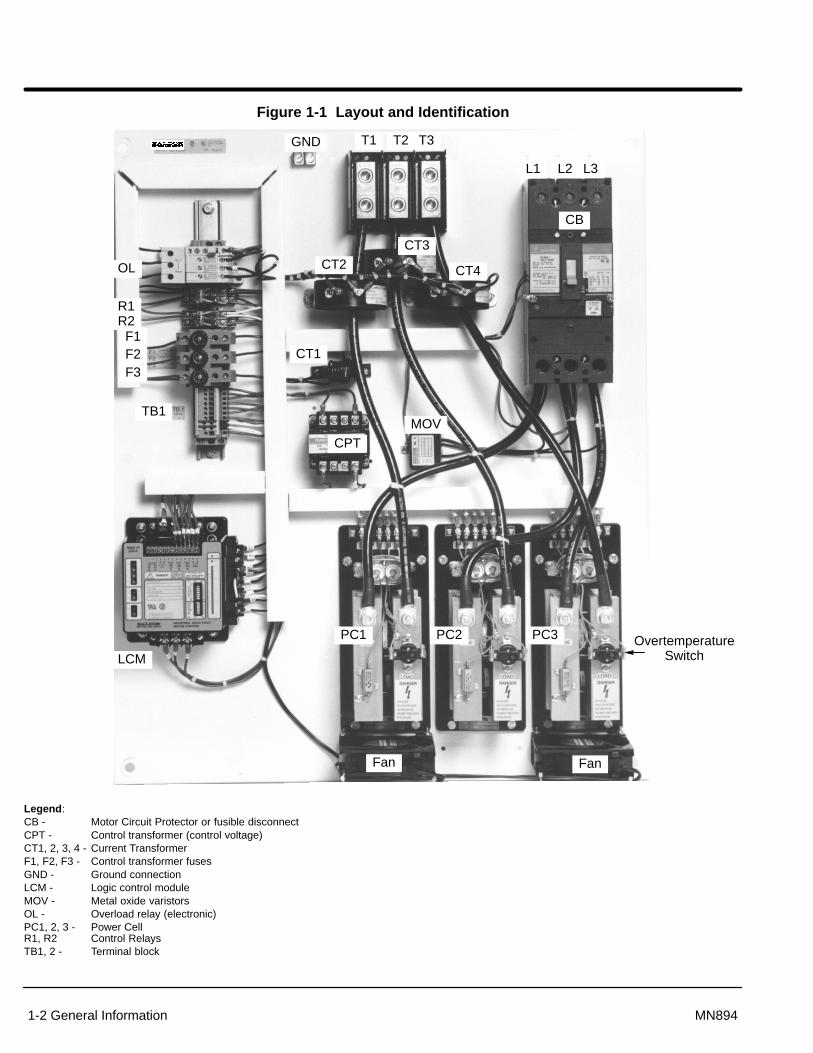
Legend:CB - Motor Circuit Protector or fusible disconnectCPT - Control transformer (control voltage)CT1, 2, 3, 4 - Current TransformerF1, F2, F3 - Control transformer fusesGND - Ground connectionLCM - Logic control moduleMOV - Metal oxide varistorsOL - Overload relay (electronic)PC1, 2, 3 - Power CellR1, R2 Control RelaysTB1, 2 - Terminal block

General Information 1-3MN894
Figure 1-2 Logic Control Module Block Diagram
123456
12
34
56
��
OFF ONS2
RDDCMOCTACHCLBP
RampModeSelect
Logic &Firing Control
CM
PFMIN MAX
RUN
RD
TD
STOP
CL
PT
RU
TUSTART
UserAdjustment
Control PowerOvercurrent TripCurrent MonitorMotor Power
End of RampShorted SCR(Shunt Trip)
400
300
200
100
0%FLA
MOTOR
CURRENT
StatusLights
Start / RunShunt Trip
Current MonitorMotor PowerEnd of Ramp
C
C
URRENT
ALIBRATION
OFF ONS1
12345678
12
34
56
78
��
CurrentTransformer
TachometerInput +
-
ResetLogic
PowerSupply
115 /230 VACPower Input
+-
Gates & Sync.
Power CellGates andCathodes
RelayOutputs
Start/Run Status
Legend:BP - BypassCL - Current LimitCM - Current MonitorOC - OvercurrentPF - Power FactorPT - Pulse TimeRD - Ramp DownRDD - Ramp Down DisableRU - Ramp UpS1 – Calibration SwitchTACH - TachometerTD - Torque DownTU - Torque Up

1-4 General Information MN894
Major Components (Refer to Figures 1-1 and 1-2).Logic Control Module (LCM)
The LCM (Logic Control Module) operates in the voltage ramp mode or current limitmode during ramp up and ramp down (if ramp down is selected). The LCM controls theamount of current that the power cells deliver to the motor during ramp up and rampdown. It uses gates and synchronous timing circuits to control the firing times of theSCR’s in the power cells. The current transformer provides the LCM with motor currentinformation. The on board current calibration switches (S1-1 thru S1-8), place burdenresistors in parallel with the current transformer to calibrate the LCM to the correct FLA(full load amperes) of the motor being used.
Current Transformer (CT1) provides starting, stopping and running current information to the LCM. Thisinformation is used to control starting and stopping current, current limit, current monitorand over current shutdown, power factor effect and motor current bar graph indicator.(CT2) is required only for sizes 160 through 840 amps. It steps down current to matchprimary rating of CT1 transformer.8, 16 and 30 amp models - CT1 is mounted inside the LCM housing.55 and 80 amp models - CT1 is mounted externally on the panel.160 to 840 amp models - CT1 and CT2 are mounted externally on the panel.CT1 ratio is 6000:1CT2 ratio is 500:5 for 160, 250 and 420 Amp models.CT2 ratio is 1000:5 for 600 and 840 Amp models.
Power Cells (PC) Power cells control the voltage delivered to the motor during ramp up and ramp down (iframp down is enabled). The LCM controls the duty cycle of the SCR’s in the power cells(“on” time versus “off” time of each SCR). A power cell contains two silicon controlledrectifiers (SCR’s). The SCR’s are solid state switches that are able to control largeamounts of current with a small amount of gate current supplied by the LCM.8, 16 and 30 amp models - six SCR’s are mounted inside the LCM housing.55 and 80 amp models - SCR’s are mounted in an isolated package containing twoSCR’s for each power cell. With this type of package, three power cells are mounted to asingle heat sink at ground potential. A temperature switch is provided in each cell toprotect the power cell from overheating.160 to 840 amp models - Each SCR is a disk type package containing one SCR. TwoSCR’s are clamped between two heat sinks. A temperature switch is provided to protectthe SCR assembly from overheating. Heat sinks are mounted on an insulated base witha terminal block and snubber network. The snubber network is a capacitor resistor seriescircuit wired in parallel with the disk type SCR’s. The snubber network enhances theelectrical characteristics of the SCR’s and provides transient voltage protection. Thisarrangement makes up one power cell. The power cell is at line potential for both lineand load terminals when line voltage is applied.
Protection DevicesMetal Oxide Varistors (MOV)
An MOV provides voltage surge protection. Voltage surges also called high voltagespikes are caused by a number of sources. Short duration high voltage spikes caused bystarting and stopping other motor loads or switching On and Off capacitor banks mayappear on the incoming lines. Transients can occur from lightning storms or from otherlightly loaded devices on the same line, such as motors, transformers, or solenoids.Electrical noise can be caused by lightning, arc welders and heat exchange equipment onthe same transformer bus line.An MOVs provide protection by absorbing or clamping these transient energy levels.High energy transients that exceed the MOV rating may damage the MOV and themultipurpose starter.
General Information 1-5MN894
Snubber Network 160 through 840 amp models only. A resistor and capacitor series circuit (snubber) iswired in parallel with each disk type SCR. The RC network enhances the electricalcharacteristics of the SCR and provides high voltage transient protection.
Shorted SCR Detection: If a shorted SCR condition is detected while starting, running or stopping, the SHUNTTRIP contact will close and the SHUNT TRIP light will indicate the condition.
The SHUNT TRIP contact is used to open the circuit breaker via a shunt trip device.Also, the shunt trip contact from the LCM module can be used to activate other circuitinterrupting device to remove the motor and control from the AC power line.
When a bypass contactor is used, the shunt trip circuit is disabled when the bypasscontactor is closed. This is accomplished by switching switch BP S2-6 On.
Over Current Shut Down: The control module has an over current detection circuit to trip and shut down the controlif motor current exceeds 450% FLA. To restart, open the Close To Run circuit, then closeit.
Current Monitor: When the motor is at speed (End of Ramp light is “ON”), the current monitor can detectover current or overload motor conditions. This warning can alert an operator or be usedto stop a motor. It can also be used for indications of jams or blockages.
Motor Overload Protection: Class 30 motor overload protection is required to protect the control and the motor fromrepetitive or extended starting conditions, as well as running during an overload condition.Class 10 or 20 overloads may trip when starting high inertia loads or when operating incurrent limit starting mode.
Over Temperature Switch: Power cells have over temperature switches to detect an overheating condition. Theswitch is an isolated bimetallic, normally closed contact. If loss of cooling causes a powercell to overheat, the temperature switch contact will open and shut down the controlcircuit.
Note: When a temperature switch opens, the control shuts down. It must be resetmanually to restart the control.
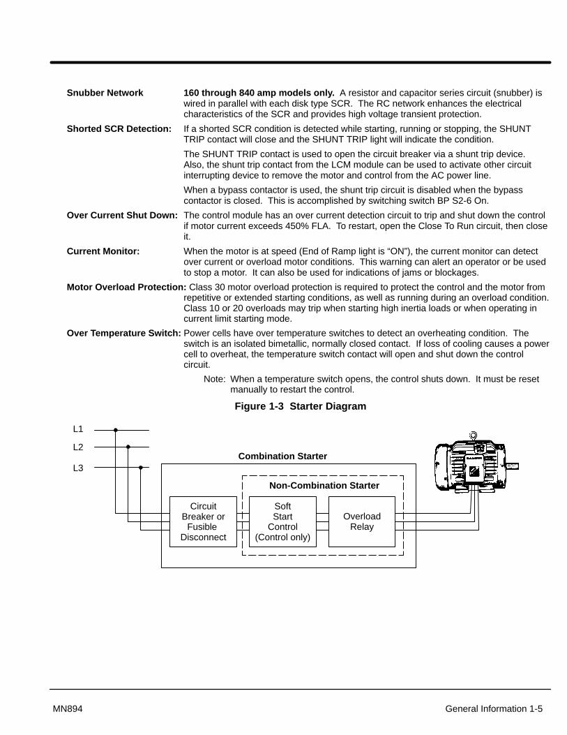
Figure 1-3 Starter Diagram
L1
L2
L3Combination Starter
Non-Combination Starter
OverloadRelay
SoftStart
Control(Control only)
CircuitBreaker or
Fusible Disconnect

1-6 General Information MN894
ConfigurationsControl Only: Soft start control, without motor overload protection or branch circuitprotection circuit breaker or fusible disconnect switch. Suitable for installation with aseries contactor or as a retrofit for an existing motor starter.
Non-combination Starter: Soft start control with motor overload protection, less branchcircuit protection circuit breaker or fusible disconnect switch. Installation with existingbranch circuit protection would use this configuration.
Combination Starter: Soft start control with motor overload protection and branch circuitprotection and branch circuit protection circuit breaker or fusible disconnect switch. Onlypush buttons are required to complete the system. New installations with no existingcontrol equipment would use this configuration.
Bypass System, Control Only: Soft start control without overload protection and branchprotection. Includes a bypass contactor to shunt the power cells after the control is in thefull run mode to eliminate heat generation across the power cells. Allows installation in aNEMA 4 or NEMA 12 enclosure.
Bypass System, Non-combination: Soft start control noncombination system withmotor overload protection, less branch circuit protection. Includes a bypass contactor toshunt the power cells after the starter is in the full run mode to eliminate heat generationacross the power cells. Allows installation in a NEMA 4 or NEMA 12 enclosure.
Bypass System, Combination: Soft start control combination system with motoroverload protection and branch circuit protection circuit breaker or fusible disconnectswitch. Includes a bypass contactor to shunt the power cells after the starter is in the fullrun mode to eliminate heat generation across the power cells. Allows installation in aNEMA 4 or NEMA 12 enclosure.
Enclosures and Ventilation: Soft start controls are available in panel mount or in NEMAtype 1, 12, 3R enclosures. The control will generate approximately 3.3 watts of heat perrunning ampere during operation. All factory supplied enclosures are designed todissipate this heat under maximum specified operating conditions. If the multipurposecontrol is mounted in an enclosure not supplied by the factory, this heat dissipation mustbe considered. Adequate ventilation or convection cooling should be provided unless abypass contactor is used.
Panel Mount: Soft start control mounted on a panel with provisions for wall or enclosureinstallation.
NEMA Type 1 (IP23): Soft start control mounted in a ventilated NEMA type 1 panelenclosure. Intended for indoor use primarily to provide a degree of protection againstcontact with enclosed electrical components. Available for all sizes and configurations.
NEMA 12/3R (IP65/IP32): NEMA 12 enclosure provides protection from dust, dirt, oiland water. NEMA 3R outdoor installation protects from rain, sleet and snow. A NEMA12/3R is shipped as a NEMA 12 and to convert to NEMA 3R, remove the drain screw atthe bottom of the enclosure.
General Information 1-7MN894
Limited Warranty
For a period of two (2) years from the date of original purchase, BALDOR willrepair or replace without charge controls and accessories which ourexamination proves to be defective in material or workmanship. Thiswarranty is valid if the unit has not been tampered with by unauthorizedpersons, misused, abused, or improperly installed and has been used inaccordance with the instructions and/or ratings supplied. This warranty is inlieu of any other warranty or guarantee expressed or implied. BALDORshall not be held responsible for any expense (including installation andremoval), inconvenience, or consequential damage, including injury to anyperson or property caused by items of our manufacture or sale. (Somestates do not allow exclusion or limitation of incidental or consequentialdamages, so the above exclusion may not apply.) In any event, BALDOR’stotal liability, under all circumstances, shall not exceed the full purchaseprice of the control. Claims for purchase price refunds, repairs, orreplacements must be referred to BALDOR with all pertinent data as to thedefect, the date purchased, the task performed by the control, and theproblem encountered. No liability is assumed for expendable items such asfuses.
Goods may be returned only with written notification including a BALDORReturn Authorization Number and any return shipments must be prepaid.

1-8 General Information MN894
Safety Notice This equipment contains voltages that may be as high as 600 volts! Electrical shock can
cause serious or fatal injury. Only qualified personnel should attempt the start-upprocedure or troubleshoot this equipment.
This equipment may be connected to other machines that have rotating parts or partsthat are driven by this equipment. Improper use can cause serious or fatal injury. Onlyqualified personnel should attempt the start-up procedure or troubleshoot this equipment.
PRECAUTIONS
WARNING: Do not touch any circuit board, power device or electrical connection before youfirst ensure that power has been disconnected and there is no high voltage presentfrom this equipment or other equipment to which it is connected. Electrical shock can cause serious or fatal injury.
WARNING: Be sure that you are completely familiar with the safe operation of this equipment.This equipment may be connected to other machines that have rotating parts orparts that are controlled by this equipment. Improper use can cause serious orfatal injury. Only qualified personnel should attempt the start-up procedure ortroubleshoot this equipment.
WARNING: Be sure the system is properly grounded before applying power. Do not apply ACpower before you ensure that all grounding instructions have been followed.Electrical shock can cause serious or fatal injury.
Caution: To prevent equipment damage, be certain that the electrical service is not capableof delivering more than the maximum line short circuit current amperes listed forthe control rating.
Caution: Do not “Megger” test the motor while it is connected to the control. Failure todisconnect motor will result in extensive damage to the control. The control istested at the factory for high voltage / leakage resistance as part of UnderwriterLaboratory requirements. Do not megger any part of the control.
Caution: Do not connect power factor correction capacitors to motor terminals. If powerfactor correction capacitors are necessary, contact Baldor.
Caution: If a brake motor is used, the initial starting voltage may not be sufficient to releasethe brake. It may be necessary to provide separate power for the brake and softstart control.
Caution: Do not connect AC incoming line power to the Motor terminals T1, T2 and T3.Connecting AC power to these terminals may result in damage to the control.
Caution: Do not supply any power to the “Close To Run” terminals. Power on these leadscan damage the control. Use a dry contact type that requires no external power tooperate.
Caution: Do not change the position of any switch while power is applied. Changing theposition of a switch during operation can damage the control and cause erraticbehavior of the load.
Caution: To prevent equipment damage, be certain that the electrical service is not capableof delivering more than the maximum line short circuit current amperes rating.
Caution: This equipment is shipped as a multipurpose apparatus. Before power is applied,the line voltage selection and the full load current calibration must be correctly set.Failure to select the proper line voltage or to calibrate the full load current maycause damage.

Section 2Installation
Installation 2-1MN894
Receiving, Inspection and StorageWhen you receive your control, there are several things you should do immediately.
1. Observe the condition of the shipping container and report any damageimmediately to the commercial carrier that delivered your control.
2. Remove the control from the carton. Inspect for shipping damage and reportany damage immediately to your commercial carrier.
3. Verify that the part number of the control you received is the same as the partnumber listed on your purchase order.
4. If the control is to be stored for several weeks before use, be sure that it isstored in a location that is clean, dry and free from corrosives andcontaminants. Storage temperatures must not exceed 140°F (60°C).
Be sure to read an become familiar with the safety notices in Section 1 of this manual.Failure to observe the product safety notices can result in injury or equipment damage. If you have questions, please contact your Baldor distributor. Do not proceed unless youunderstand the installation and operation requirements and safety notices.
Physical Location The location of the soft start control is important. It should be installed in an area that isprotected from direct sunlight, corrosives, harmful gases or liquids, dust, metallicparticles, and vibration. Exposure to these elements can reduce the operating life anddegrade performance of the control.
Several other factors should be carefully evaluated when selecting a location forinstallation:
1. For effective cooling and maintenance, the control should be mounted verticallyon a flat, smooth, non-flammable vertical surface. Heat dissipation of 3.3 wattsper running FLA of the motor must be provided. All factory supplied enclosuresprovided adequate heat dissipation.
2. If the control is mounted in an enclosure, sufficient air flow must be provided.The fan or blower must be rated for at least 0.8 cubic feet per minute for eachampere of motor FLA rating.
3. Keep high voltage and low voltage wiring separated. If the conduits mustcross, be sure that they cross at 90° angles only.
1. Motor overload protection is required for starters that do not have an overloadprotection device.
2. The multipurpose soft starter is suitable for use on a circuit capable ofdelivering no more than the short circuit ARMS listed in Table 2-1.
3. A short circuit current and overcurrent devices are required for soft startcontrols that do not have a circuit breaker or fusible disconnect switch.
AC Main CircuitProtection Devices Be sure a suitable input power protection device is installed. Use the recommended circuit
breaker or fuses listed in Table 2-1. Wire sizes and protective device specifications are basedon the maximum output power rating of the control.
Power Disconnect A power disconnect should be installed between the input power service and the control fora fail safe method to disconnect power. The control will remain in a powered-up condition untilall input power is removed from the control and internal voltages are depleted.

2-2 Installation MN894
Table 2-1 Three Phase
Fuse MCP (GE)Rating(AMPS) Amps Class Short Circuit
ARMSAmps Type Short Circuit
ARMS
8 100 J 5,000 20 5,00016 100 J 5,000 20 5,00030 200 or
100J orRK1
5,000 50 5,000
55 175 J 42,000 100 SELA 10,00080 175 J 42,000 100 SFLA 10,000160 400 RK5 100,000 300 SGLA 42,000250 400 RK5 100,000 300
SKLA42,000
420 800 L 100,000 600 42,000600 800 L 100,000 600 42,000840 1200 L 100,000 600 42,000
Note: Recommended fuses/breakers are based on 25°C ambient, maximum continuous current.
Figure 2-4 Multipurpose Control Terminal Locations
T1 T2 T3
L1 L2 L3
(A) Line Input
(A) Motor Output Load
(C) Control Connections
(D) GND
(D) GND

Installation 2-3MN894
Installation1. Mount the panel or enclosure to the mounting surface. The panel or enclosure must be
securely fastened to the mounting surface. Refer to the mounting dimensions in Section 6 ofthis manual.
2. Ground the panel and control per NEC article 250 as well as state and local codes.3. Use copper wire rated for at least 75°C. Refer to Figure 2-4 and Table 2-2 for wire size
recommendations.4. Connect the incoming AC power wires from the power disconnect and/or protection devices to
L1, L2 and L3 terminals. Tighten each terminal as specified in Figure 2-4 and Table 2-2.5. * Connect earth ground to the “GND” of the control. Be sure to comply with local codes.6. Verify the input line voltage is correct.7. For MA#–XX models, verify the line voltage selection jumpers on the LCM module are properly
set. For MB#–XX models, verify the control transformer primary taps are connected for the linevoltage applied.
8. Connect the three phase power leads of the AC motor to terminals T1, T2, and T3 of the MainCircuit Terminals.
9. * Connect motor ground wire to the “GND” of the control. Be sure to comply with all applicablecodes.
Caution: Do not supply any power to the “Close To Run” terminals. Poweron these leads can damage the control. Use a dry contact type thatrequires no external power to operate.
10. Connect the remaining control terminals as required for your installation. Refer to Figure 2-4 andTable 2-2 for wire size and terminal torque specifications.
* Grounding by using conduit or panel connection is not adequate. A separate conductor of theproper size must be used as a ground conductor.Table 2-2 Recommended Wire Size and Tightening Torque
Torque Wire SizeStarter Rating Terminal
lb-in Nm AWG mm2
A 20 2.5 10-16 6-1.5B 35 4 8 10
8, 16 and 30 AMPS C 12 1.4 12-22 4-0.34D 45 5.1 6-14 16-2.5A Note 1 Note 1 Note 2 Note 2B Note 1 Note 1 Note 2 Note 2
55 through 840 AMPS C 12 1.4 12-22 4-0.34D 45 5.1 6-14 16-2.5
All wire sizes based on 75°C copper wire, 3% line impedance. Higher temperature smaller gauge wire may be used per NEC and local codes.
Note1: Refer to the label on the equipment panel for line and load tightening torque values.Note2: Line and Load wires sizes for 55 through 840 AMP models are as follows:
Wire SizeAMPS
AWG mm2
55 4 2580 3 30
160 3/0 95250 350 mcm 185420 2x 300 mcm 2x 150600 2x 500 mcm 2x 240840 3x 500 mcm 2x 240
2-4 Installation MN894
Non-Motor and Special Motor Applications
Non-motor load: The multipurpose control is designed to provide reduced starting voltage for standardthree phase induction motors. The control may also start non-motor loads for controlledinrush current applications with resistive or inductive loads. Consult Baldor if the controlis to be used with a non-motor load.
Wye-Delta or The multipurpose control can replace an existing wye-delta or part winding starter.Part Winding Starter: Begin by removing the existing contactors. Wire the motor in its “RUN” delta
configuration and connect the motor to the control. The control can be used as if it werecontrolling a standard design B motor.
Wound Rotor Motors: Consult Baldor if the control is to be used with a wound rotor or slip ring type motor. Thistype of load produces high starting torque with reduced starting current and speed. Themultipurpose control provides low starting current and low starting torque. Themultipurpose control can be used for applications that do not require high starting torqueand a continuous speed reduction.
High Slip Motors: The multipurpose control can be used with high slip motors, such as design D. Thesemotors are used with large inertial loads that require extended starting times. Reducedstarting voltage will reduce the starting current and extend the starting time. Long startingtimes may require using slow trip overloads. However, the thermal capabilities of themotor and control must be evaluated before extending the overload trip times.
Reversing Applications: For reversing applications, two multipurpose controls can be used or a reversingcontactor can be used. Consult Baldor for more information.
Multispeed Motors: Consult Baldor if the control is to be used with a multispeed motor. The control canbe used with a multispeed motor if a multispeed starter is connected between the controland the motor. In this case, an additional MOV must be connected to the terminal side ofthe control. Switching is normally done be auxiliary contacts from the multispeed starterthat are connected to the control circuit of the multipurpose control.
Motors on Grounded and A multipurpose starter should not be used with “Delta” or “Open” ground systems. open delta systems: Without a proper ground, the circuit to detect a shorted SCR condition may malfunction or
may not be able to detect a shorted SCR condition.

Section 3Operation
Operation 3-1MN894
Types of Starting
VoltageRamp
% LineVoltage
25
50
75
100RU
TD
CL
RDTU
Time0
PT
CurrentLimit
% FLA
100
200
300
400
CL RD
Time0
PT
Tach
% FullSpeed
25
50
75
100 RU
RUN
RD
Time0
Voltage Starting (S2-4 = OFF)During start the initial voltage (TU) is set to a level where themotor will begin to turn when power is applied. The ramp time(RU) is adjustable to provide a smooth start. The pulse time(PT) is used for high friction loads to break loose “frozen” loadswith up to 400% FLA.If a ramp down function is needed, the initial voltage TD settingis used to lower voltage to a level where the motor will begin toslow down when the stop button is pushed. Ramp down (RD)can only extend motor stopping time preventing sudden stoppingproblems such as water hammer.
Current Limit Starting (S2-5 = ON)
If current limit starting is selected the starter will operate similarto voltage starting. On high inertia loads such as chippers andgrinders the Current Limit (CL) setting is what determines thestarting time. The starter will provide that current regardless ofthe ramp time setting. The CL setting must be high enough toprovide enough starting current in all starting conditions. Rampdown (RD) can only extend motor stopping time preventingsudden stopping problems such as water hammer.
Tach Feedback Starting (S2-4 = ON)
Tach feedback starting/stopping uses a 0-10 VDC Tach signal.The control will provide voltage to the motor to generate asmooth linear starting even under cycling load conditions. Rampdown (RD) can only extend motor stopping time preventingsudden stopping problems such as water hammer.
3-2 Operation MN894
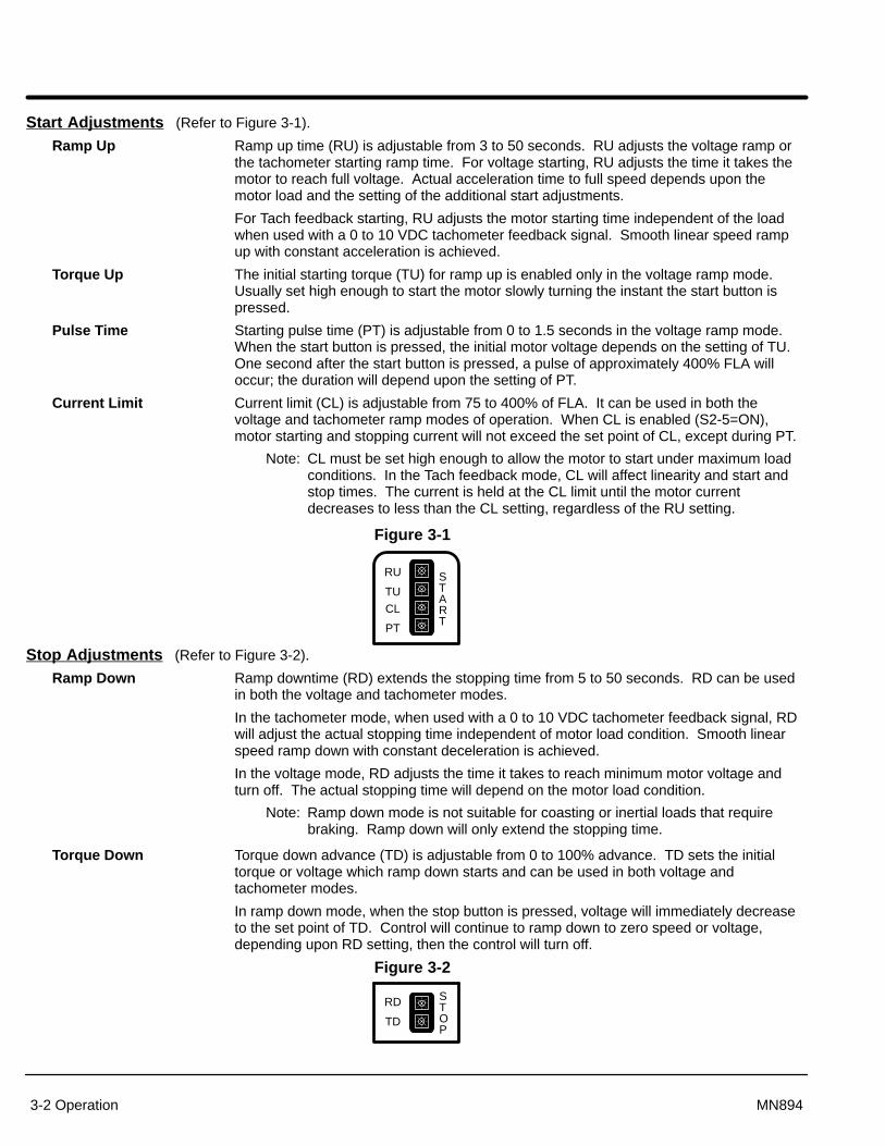
Start Adjustments (Refer to Figure 3-1).
Ramp Up Ramp up time (RU) is adjustable from 3 to 50 seconds. RU adjusts the voltage ramp orthe tachometer starting ramp time. For voltage starting, RU adjusts the time it takes themotor to reach full voltage. Actual acceleration time to full speed depends upon themotor load and the setting of the additional start adjustments.
For Tach feedback starting, RU adjusts the motor starting time independent of the loadwhen used with a 0 to 10 VDC tachometer feedback signal. Smooth linear speed rampup with constant acceleration is achieved.
Torque Up The initial starting torque (TU) for ramp up is enabled only in the voltage ramp mode.Usually set high enough to start the motor slowly turning the instant the start button ispressed.
Pulse Time Starting pulse time (PT) is adjustable from 0 to 1.5 seconds in the voltage ramp mode.When the start button is pressed, the initial motor voltage depends on the setting of TU.One second after the start button is pressed, a pulse of approximately 400% FLA willoccur; the duration will depend upon the setting of PT.
Current Limit Current limit (CL) is adjustable from 75 to 400% of FLA. It can be used in both thevoltage and tachometer ramp modes of operation. When CL is enabled (S2-5=ON),motor starting and stopping current will not exceed the set point of CL, except during PT.
Note: CL must be set high enough to allow the motor to start under maximum loadconditions. In the Tach feedback mode, CL will affect linearity and start andstop times. The current is held at the CL limit until the motor currentdecreases to less than the CL setting, regardless of the RU setting.
Figure 3-1
CL
PT
RU
TUSTART
Stop Adjustments (Refer to Figure 3-2).
Ramp Down Ramp downtime (RD) extends the stopping time from 5 to 50 seconds. RD can be usedin both the voltage and tachometer modes.
In the tachometer mode, when used with a 0 to 10 VDC tachometer feedback signal, RDwill adjust the actual stopping time independent of motor load condition. Smooth linearspeed ramp down with constant deceleration is achieved.
In the voltage mode, RD adjusts the time it takes to reach minimum motor voltage andturn off. The actual stopping time will depend on the motor load condition.
Note: Ramp down mode is not suitable for coasting or inertial loads that requirebraking. Ramp down will only extend the stopping time.
Torque Down Torque down advance (TD) is adjustable from 0 to 100% advance. TD sets the initialtorque or voltage which ramp down starts and can be used in both voltage andtachometer modes.
In ramp down mode, when the stop button is pressed, voltage will immediately decreaseto the set point of TD. Control will continue to ramp down to zero speed or voltage,depending upon RD setting, then the control will turn off.
Figure 3-2
RD
TD
STOP

Operation 3-3MN894
Run Adjustments (Refer to Figure 3-3).
Current Monitor Current monitor set point (CM) is adjustable from 50 to 400% FLA to monitor the runningcurrent after the motor reaches the full run condition.
With CM enabled (S2-2=ON), if the running current exceeds the CM set point, the controlwill shut down, the CUR MON contact will close, and the light will illuminate.
With CM disabled (S2-2=OFF), if motor current exceeds CM set point, the control will notshut down, the CUR MON contact will close and the light will illuminate.
Power Factor Power factor effect (PF) is adjustable from 0 to 100%. PF is used to adjust the maximumvoltage applied to the motor under lightly loaded conditions to minimize motor currentwith minimum motor load.
PF is enabled after the motor reaches full on condition.
PF should be turned off (CCW) if more than one motor is used with one control or if aby-pass contactor is used.
Note: PF adjustment has no effect in bypass mode.
Figure 3-3
CM
PFMIN MAX
RUN
Current Calibration Switch Refer to the multipurpose control Current Calibration Chart in Appendix A. Set switchesS1 to the motor FLA rating. Calibration is based on the motor nameplate full loadamperes (FLA), not necessarily actual running current. Motors with more than 6 timeslocked rotor current may require a higher setting to start properly.
Operating Parameters Switch (Refer to Figure 3-4).Switches S2-1 thru S2-6 select the operating modes that best fit the application.
S2-1 Ramp Down Disable (RDD). In the “On” position: When the stop button is pressed, the control will immediately turn off.User stop adjustments RD (ramp down time) and TD (ramp down initial starting torque)are disabled.
In the “Off” position: When the stop button is pressed, the control will ramp down. In thevoltage mode of operation, ramp down time depends on RD and TD settings and the loadcondition.
S2-2 Current Monitor (CM) “On” position: If the motor running current exceeds the Current Monitor (CM) setting, thecontrol will shut down. The shut down condition is indicated by the current monitor lightand the closure of the current monitor contact. The current monitor is typically used toshut the control down when a jam occurs. To restart the control, press stop, then start; oropen the close to run circuit, then close it.
“Off” position: If motor running current exceeds the current monitor setting, the currentmonitor light and contact will indicate this condition but the control will not shut down.The current monitor can be used as an over and under current monitor.
S2-3 Over Current Indicator (OC).“On” position: If an over current trip occurs (current exceeds 450% FLA), the control willshut down and the condition will be indicated by the OC light and CM light and theclosure of the current monitor contact. To restart the control, press stop then start; oropen the close to run circuit, then close it.
“Off” position: An over current trip is indicated by the over current light and will not affectthe current monitor. The control will shut down.
3-4 Operation MN894
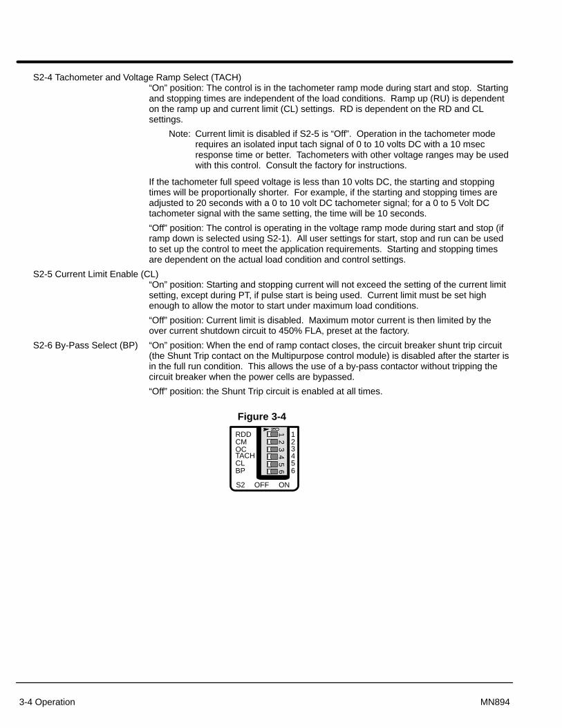
S2-4 Tachometer and Voltage Ramp Select (TACH)“On” position: The control is in the tachometer ramp mode during start and stop. Startingand stopping times are independent of the load conditions. Ramp up (RU) is dependenton the ramp up and current limit (CL) settings. RD is dependent on the RD and CLsettings.
Note: Current limit is disabled if S2-5 is “Off”. Operation in the tachometer moderequires an isolated input tach signal of 0 to 10 volts DC with a 10 msecresponse time or better. Tachometers with other voltage ranges may be usedwith this control. Consult the factory for instructions.
If the tachometer full speed voltage is less than 10 volts DC, the starting and stoppingtimes will be proportionally shorter. For example, if the starting and stopping times areadjusted to 20 seconds with a 0 to 10 volt DC tachometer signal; for a 0 to 5 Volt DCtachometer signal with the same setting, the time will be 10 seconds.
“Off” position: The control is operating in the voltage ramp mode during start and stop (iframp down is selected using S2-1). All user settings for start, stop and run can be usedto set up the control to meet the application requirements. Starting and stopping timesare dependent on the actual load condition and control settings.
S2-5 Current Limit Enable (CL)“On” position: Starting and stopping current will not exceed the setting of the current limitsetting, except during PT, if pulse start is being used. Current limit must be set highenough to allow the motor to start under maximum load conditions.
“Off” position: Current limit is disabled. Maximum motor current is then limited by theover current shutdown circuit to 450% FLA, preset at the factory.
S2-6 By-Pass Select (BP) “On” position: When the end of ramp contact closes, the circuit breaker shunt trip circuit(the Shunt Trip contact on the Multipurpose control module) is disabled after the starter isin the full run condition. This allows the use of a by-pass contactor without tripping thecircuit breaker when the power cells are bypassed.
“Off” position: the Shunt Trip circuit is enabled at all times.
Figure 3-4
123456
12
34
56
��
OFF ONS2
RDDCMOCTACHCLBP

Operation 3-5MN894
Control Connections (Refer to Figure 3-5).
CLOSE TO RUN Close to Run terminals 12 and 13. Close to run contact must be closed to initiate rampup and run. Close to Run contact must be opened to initiate ramp down to stop. Close torun contact must be dry and electrically isolated contact. If a voltage is applied to theseterminals, the control may be damaged.
When the Close to Run circuit is closed, the Start/Run light will be on and the contact willclose. This normally open contact is typically used to seal in the start button circuit.
START/RUN Start/Run light and contact terminals 10 and 11. As long as the Closed to Run circuitremains closed, the Start/Run light and contact will remain activated. This condition alsoapplies to an over current or a current monitor shutdown.
SHUNT TRIP Shunt Trip light and contact terminals 8 and 9. If the control detects a shorted SCR condition,the shunt trip light will be on and the contact will close. The shunt trip contact is used tooperate a Shunt Trip device in the circuit breaker or similar disconnection means to removethe motor and controller from the line should a shorted SCR condition occur.
The shunt trip circuit may also detect loss of phase or low voltage on a phase. The circuitmay not work properly on grounded delta systems or open delta systems. The Shunt Tripcircuit will trip when energized on single phase or an unbalanced line voltage.
RAMP END Ramp End light and contact terminals 6 and 7. In the voltage or the tachometer modes,when the starting ramp is completed and the control is in the full run mode, the ramp endlight will be on and the contact will close. The starting current limit is then disabled andCUR MON (running current monitor) is enabled.
Note: Since most loads do not require full voltage and torque to reach full speed,when control is in the voltage ramp mode, the motor will reach full speedbefore the ramp end contact and light are activated. Ramp end will only beactivated after the motor and control reach full voltage.
The ramp end contact can be used to turn on other equipment. The ramp end contactcan be used to close the bypass contactor to reduce heat dissipation of the SCRs.
TACH Tachometer input terminals 4 and 5. The TACH input is used in the tachometer mode(S2-4=ON). The input required for TACH feedback is a 0 to 10 volt DC signal with amaximum 10 ms response time.
MTR PWR Motor Power light and contact at terminals 2 and 3. Indicates that voltage and current aresupplied to the motor. If a current monitor or an over current shut down condition occurs,the contact is deactivated and the light is turned off.
CUR MON Current Monitor light and contact terminals 1 and 2. A user adjusted monitor. Maximumrunning current is adjustable from 50% to 400% FLA. Switch S2-2 controls the CMmonitor.
S2-2 “On” position: If motor current exceeds the CUR MON setting, the light will be onand the contact will close. In addition, the motor power and ramp end LEDs will be offand their contacts will open. The control will shut down. The Start/Run light will stay onand the contact will remain closed. Typically used to shut down the control in case of amechanical jam. To restart a CUR MON shutdown, press stop then start; or open theclose to run circuit, then close it.
S2-2 “Off” position: If current exceeds the CUR MON setting, the light will be on and thecontact will close for the duration of the over current. The control will not shut down. Inthis mode, the CUR MON monitor can be used as an over and under current monitor.
Figure 3-5
CLOSETO RUN
START/ RUN
SHUNTTRIP
RampEnd
TachMTRPWR
CURMON
+ –

3-6 Operation MN894
IndicatorsPower On The PWR light indicates that power is supplied to the internal power supply of the control.
WARNING: If the power light is not illuminated, it does not necessarily meanthat the line voltage is off. Electrical shock hazard may exist.Measure the voltage at the line terminals before service.
Over Current OC over current shutdown LED. If the control shuts down due to an over currentcondition (motor current is greater than 450% FLA), the OC light will be on. To restart thecontrol, press stop, then start; or open the close to run circuit, then close it.
Motor Current The Motor Current display is a 10 segment bar graph representation of motor currentfrom 0 to 400% FLA. Used to check ramp up, run and ramp down current conditionswhile the control is in operation.
Summary of Start and Stop SequencesTo Start the Motor: Close 12 - 13 (Close to Run) and the following occurs:
1. 10 - 11 close to confirm start command.
2. 2 - 3 close when power is applied to motor. Ramp up cycle begins.
3. 6-7 close at the end of ramp up cycle.
To Stop the Motor: Open 12 - 13 (Close to Run) and the following occurs:
1. 10 - 11 open to confirm stop command.
2. 6-7 opens immediately.
3. 2 - 3 operation depend on ramp down mode selection:With Ramp Down: 2 - 3 opens when ramp down is complete.Without Ramp Down: 2 - 3 opens immediately.
Shunt Trip: During normal operation, detection of a shorted SCR, misfiring SCR will cause the following:
1. 8 - 9 close immediately.
2. Shunt Trip light turns ON.
3. The shunt trip breaker is immediately tripped and all power is removed from thecontrol and motor.
Note: The shunt trip breaker will only trip if it is connected to the shunt trip contact atterminals 8 & 9.

Section 4Start-up
Start-up 4-1MN894
Safety Notice Be sure to read and understand all notices, warning and caution statements in Section 1of this manual. If you have any questions about the safe operation of this equipment,please contact your Baldor representative before you proceed.
Start-up ChecklistRecommended Equipment Volt meter (20k� per volt or better, true RMS meter).
Clamp on ammeter (5 times FLA full scale).Adjustment wand (provided with multipurpose soft start control).
Overview The following adjustment procedures are examples and are intended to be used as aguideline to match motor starting characteristics to the load. Actual loads may becharacterized by one or more of the examples. These procedures are intended to helpyou design your own procedure for your specific application.
Keep in mind that reducing the starting current by one half will reduce the starting torqueby one fourth. This will cause the motor to take four times longer to reach full speed. Insituations where overloads tend to trip because of long starting times, increase thestarting current and decrease the ramp up time (RU) to help eliminate nuisance trips.
The potentiometer adjustments have a maximum span of 270°. Use the adjustmentwand (provided) to adjust these devices and do not force the adjustments beyond theirmechanical stops.
Caution: This equipment is shipped as a multipurpose apparatus. Before power is applied,the line voltage selection and the full load current calibration must be correctly set.Failure to select the proper line voltage or to calibrate the full load current maycause damage.Switches S1 and S2 as well as all potentiometer adjustments are not factory preset.These will be set during the example procedures given in this section.
Before you apply Power� Verify the installation procedure has been performed correctly.
� Know if your application is one of the “Non-motor and Special MotorApplications” described in Section 2.
� Verify the wiring to the motor does not have any short circuits.
� Verify the motor is properly connected. Verify the voltage and full load amprating on the motor nameplate.
Note: A load must be connected to the control for testing. If the actual load cannotbe connected, connect any small motor temporarily for testing.
� Verify that the control transformer is properly jumpered for the line voltage atyour location. (MB#–XXX models).
� Verify that the control module jumper is correctly set for the line voltage.(MA#–XXX models).
� Set S1 to the motor nameplate FLA value.
� Set S2 for the type of application.� Set potentiometers as suggested.
� Verify the overload setting corresponds to the full load current range on thecalibration label.
After you apply Power� Verify the input voltage to the starter and the 115VAC from the control
transformer (if a control transformer is installed).
� Verify the PWR light is on. (If not, refer to troubleshooting).
� Verify the shunt trip light is OFF. If it is ON, verify the motor is connected andall three motor phases are present. If the motor is connected and the shunt triplight is on, do not attempt to start the control. A short in the motor or wiring mayexist.
� Perform the starting procedure for your application.

4-2 Start-up MN894
Quick Set-Up 1. Check continuity of the motor wiring and check for phase to phase and phase to ground short circuits.
2. Connect the control wiring for your application. (Refer to section 2 for wire size and torque specifications).
3. For MB#–XXX models, verify the control transformer is set for the line voltage. For MA#–XXX models, verify proper voltage jumper selection on LCM models.
4. Calibrate S1. Refer to Appendix A for switch settings.
Voltage Ramp Starting - (Fans or lightly loaded motors)
5. Set for ramp up with ramp down as follows:S2-1 = OFF Ramp down disableS2-2 = OFF Current monitorS2-3 = OFF Over current shut downS2-4 = OFF Tachometer enableS2-5 = OFF Current limit enableS2-6 = OFF Bypass contactorSet RU, TU, PT and PF fully CCW.Set RD and RT at mid point.
6. Set for ramp up with no ramp down as follows:S2-1 = ON Ramp down disableS2-2 = OFF Current monitorS2-3 = OFF Over current shut downS2-4 = OFF Tachometer enableS2-5 = OFF Current limit enableS2-6 = OFF Bypass contactorSet RU, TU, PT and PF fully CCW.
Note: If the control OC trips, use Current Ramp Starting.
7. Continue with step 14.
Current Ramp Starting - (High inertial loads)
8. Set for ramp up with ramp down as follows:S2-1 = OFF Ramp down disableS2-2 = OFF Current monitorS2-3 = OFF Over current shut downS2-4 = OFF Tachometer enableS2-5 = ON Current limit enableS2-6 = OFF Bypass contactorSet RU, TU, PT and PF fully CCW.Set RD and RT at mid point.
9. Set for ramp up with no ramp down as follows:S2-1 = ON Ramp down disableS2-2 = OFF Current monitorS2-3 = OFF Over current shut downS2-4 = OFF Tachometer enableS2-5 = ON Current limit enableS2-6 = OFF Bypass contactorSet TU, PT, RD, TD and PF fully CCW.Set RU fully CW.Set CL to midpoint.
10. Continue with step 14.
Start-up 4-3MN894
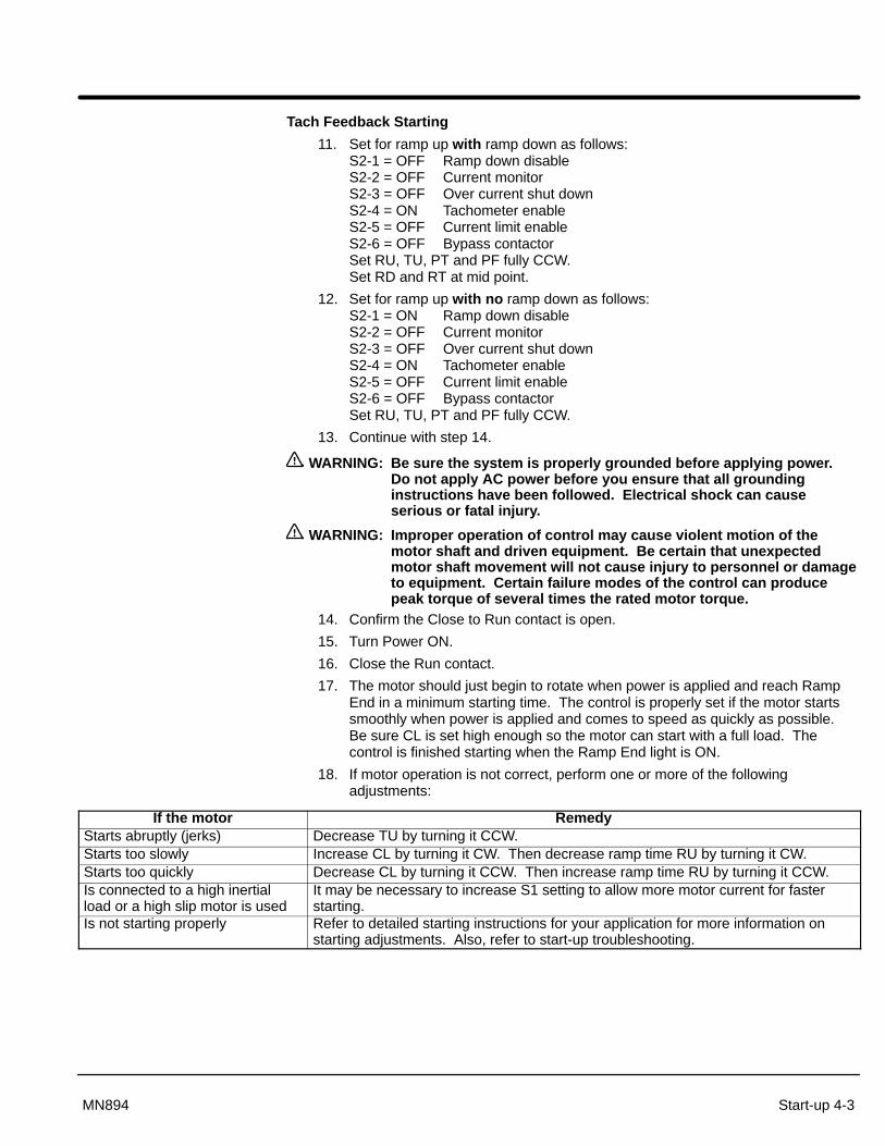
Tach Feedback Starting
11. Set for ramp up with ramp down as follows:S2-1 = OFF Ramp down disableS2-2 = OFF Current monitorS2-3 = OFF Over current shut downS2-4 = ON Tachometer enableS2-5 = OFF Current limit enableS2-6 = OFF Bypass contactorSet RU, TU, PT and PF fully CCW.Set RD and RT at mid point.
12. Set for ramp up with no ramp down as follows:S2-1 = ON Ramp down disableS2-2 = OFF Current monitorS2-3 = OFF Over current shut downS2-4 = ON Tachometer enableS2-5 = OFF Current limit enableS2-6 = OFF Bypass contactorSet RU, TU, PT and PF fully CCW.
13. Continue with step 14.
WARNING: Be sure the system is properly grounded before applying power.Do not apply AC power before you ensure that all groundinginstructions have been followed. Electrical shock can causeserious or fatal injury.
WARNING: Improper operation of control may cause violent motion of themotor shaft and driven equipment. Be certain that unexpectedmotor shaft movement will not cause injury to personnel or damageto equipment. Certain failure modes of the control can producepeak torque of several times the rated motor torque.
14. Confirm the Close to Run contact is open.
15. Turn Power ON.
16. Close the Run contact.
17. The motor should just begin to rotate when power is applied and reach RampEnd in a minimum starting time. The control is properly set if the motor startssmoothly when power is applied and comes to speed as quickly as possible.Be sure CL is set high enough so the motor can start with a full load. Thecontrol is finished starting when the Ramp End light is ON.
18. If motor operation is not correct, perform one or more of the followingadjustments:
If the motor RemedyStarts abruptly (jerks) Decrease TU by turning it CCW.Starts too slowly Increase CL by turning it CW. Then decrease ramp time RU by turning it CW.Starts too quickly Decrease CL by turning it CCW. Then increase ramp time RU by turning it CCW.Is connected to a high inertialload or a high slip motor is used
It may be necessary to increase S1 setting to allow more motor current for fasterstarting.
Is not starting properly Refer to detailed starting instructions for your application for more information onstarting adjustments. Also, refer to start-up troubleshooting.

4-4 Start-up MN894
Starting Instructions Choose one of the following examples that best matches your application. Read theprocedure and set the control according to the procedure or use the steps to developyour own procedure.
Variable Load with Voltage Ramp (S2-2=OFF, S2–4=OFF)
Typically used for non-inertial loads, loads that increase with speed and changing loads,such as axial fans and pumps.
1. Set RU, TU, PT, RD, TD and PF fully counterclockwise CCW).
2. Set CL and CM fully clockwise (CW).
3. Adjust TU clockwise sufficiently to start load slowly moving at moment ofswitching.
4. Adjust RU clockwise to achieve desired starting time with normal loadconditions.
Note: Proceed to “Running Adjustment Procedure” if ramp down is not used.
5. Adjust TD clockwise sufficiently to cause the load to slow down soon after thestop button is pressed, with normal load conditions.
6. Adjust RD clockwise to achieve desired stopping time with normal loadconditions.
Running Adjustment Procedure:
After adjusting the starting and stopping characteristics, current monitor/trip (CM)and power factor adjustments can be made. If the power factor circuit is not used,turn the PF adjustment fully counterclockwise.
Power Factor Correction Adjustment (PF):
1. Use an ammeter to measure motor running current.
2. With the motor at full speed, minimum load and the “Ramp End” light ON,adjust PF clockwise to minimize running current without oscillation. If there isno noticeable drop in current, repeat this step while measuring motor voltage.
Current Monitor/Trip (CM):
1. Set S2-2=OFF.
2. Press start and allow the motor to reach full speed and the “Ramp End” light toturn ON.
3. Adjust CM to desired threshold by observing the “CUR MON” light.
4. The “CUR MON” contact can be used to indicates this threshold, or by settingthe S2-2=ON, the starter will shut down. Press stop to reset the shutdown andtrip condition.
Post Adjustment Check List:
1. Check fans for proper operation.
2. If bypass contactor is used, check that the contactor is closing at Ramp End.
3. Using a current probe, measure current on all three motor phases. Be sure thecurrent is balanced during ramp on, run and ramp down.
4. With the motor in run mode (Ramp End light “ON”), check phase current of allthree phases. Currents should be balanced and within nameplate FLA.
5. Measure the line voltage at the control during ramp up to ensure voltage doesnot drop below minimum operating voltage.
Start-up 4-5MN894
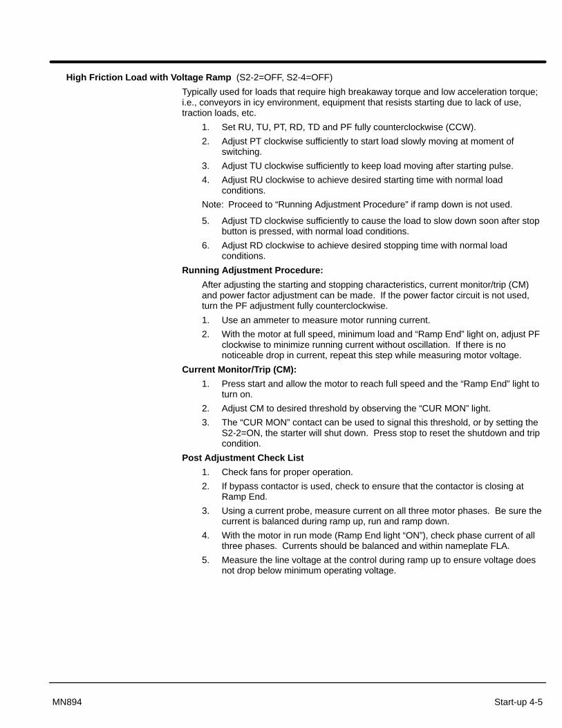
High Friction Load with Voltage Ramp (S2-2=OFF, S2-4=OFF)
Typically used for loads that require high breakaway torque and low acceleration torque;i.e., conveyors in icy environment, equipment that resists starting due to lack of use,traction loads, etc.
1. Set RU, TU, PT, RD, TD and PF fully counterclockwise (CCW).
2. Adjust PT clockwise sufficiently to start load slowly moving at moment ofswitching.
3. Adjust TU clockwise sufficiently to keep load moving after starting pulse.
4. Adjust RU clockwise to achieve desired starting time with normal loadconditions.
Note: Proceed to “Running Adjustment Procedure” if ramp down is not used.
5. Adjust TD clockwise sufficiently to cause the load to slow down soon after stopbutton is pressed, with normal load conditions.
6. Adjust RD clockwise to achieve desired stopping time with normal loadconditions.
Running Adjustment Procedure:
After adjusting the starting and stopping characteristics, current monitor/trip (CM)and power factor adjustment can be made. If the power factor circuit is not used,turn the PF adjustment fully counterclockwise.
1. Use an ammeter to measure motor running current.
2. With the motor at full speed, minimum load and “Ramp End” light on, adjust PFclockwise to minimize running current without oscillation. If there is nonoticeable drop in current, repeat this step while measuring motor voltage.
Current Monitor/Trip (CM):
1. Press start and allow the motor to reach full speed and the “Ramp End” light toturn on.
2. Adjust CM to desired threshold by observing the “CUR MON” light.
3. The “CUR MON” contact can be used to signal this threshold, or by setting theS2-2=ON, the starter will shut down. Press stop to reset the shutdown and tripcondition.
Post Adjustment Check List
1. Check fans for proper operation.
2. If bypass contactor is used, check to ensure that the contactor is closing atRamp End.
3. Using a current probe, measure current on all three motor phases. Be sure thecurrent is balanced during ramp up, run and ramp down.
4. With the motor in run mode (Ramp End light “ON”), check phase current of allthree phases. Currents should be balanced and within nameplate FLA.
5. Measure the line voltage at the control during ramp up to ensure voltage doesnot drop below minimum operating voltage.

4-6 Start-up MN894
Inertial Load (S2-1=ON, S2-4=OFF, S2-5=ON)
Typically used on coasting and/or flywheel loads; i.e., chippers, centrifuges, compressors,crushers, chillers, band saws, centrifugal fans and blowers.
Note: Ramp down and pulse start are not normally used with inertial loads.
1. Set TU, PT, RD, TD and PF fully counterclockwise (CCW).
2. Set RU approximately 90% clockwise.
3. Set CL to midpoint.
4. Set CM fully clockwise (CW).
5. Adjust CL sufficiently to allow motor to reach full speed in desired time withmaximum normal load.
Running Adjustment Procedure:
After adjusting the starting and stopping characteristics, current monitor/trip (CM)and power factor adjustment can be made. If the power factor circuit is not used,turn the PF adjustment fully counterclockwise.
Power Factor Correction Adjustment (PF):
1. Use an ammeter to measure motor running current.
2. With the motor at full speed, minimum load and the “Ramp End” light ON,adjust PF clockwise to minimize running current without oscillation. If there isno noticeable drop in current, repeat this step while measuring motor voltage.
Current Monitor/Trip (CM):
1. Set S2-2=OFF.
2. Press start and allow the motor to reach full speed and the “Ramp End” light toturn ON.
3. Adjust CM to the desired threshold by observing the “CUR MON” light.
4. The “CUR MON” contact can be used to signal this threshold, or by settingS2-2=ON, the starter will shut down. Press stop to reset the shutdown and tripcondition.
Post Adjustment Check List:
1. Check fans for proper operation.
2. If a bypass contactor is used, check that the contactor closes at ramp end.
3. Using a current probe, measure current on all three motor phases. Be sure thecurrent is balanced during ramp up, run and ramp down.
4. With the motor in run mode (ramp end light “ON”), check phase current of allthree phases. Currents should be balanced and within nameplate FLA.
5. Measure the line voltage at the control during ramp up to ensure voltage doesnot drop below minimum operating voltage.

Start-up 4-7MN894
Tachometer Mode (S2-4=ON, S2-5=OFF)
Typically used for changing loads that require consistent starting and stopping times,independent of load condition, and pumping applications with severe head pressure toreduce water hammer; i.e., pumps, conveyors, stackers and other material handlingequipment.
1. Set RU, TU, PT, RD, TD and PF fully counterclockwise (CCW).
2. Set CL and CM fully clockwise (CW).
3. Adjust RU and RD for desired ramp up and ramp down time. RD is onlyeffective with S2-1=OFF.
Running Adjustment Procedure:
After adjusting the starting and stopping characteristics, the current monitor/trip (CM)and power factor correction circuit (PF) can be adjusted. If the power factor circuit isnot used, turn the PF adjustment fully counterclockwise.
Power Factor Correction Adjustment (PF):
1. Use an ammeter to measure motor running current.
2. With the motor at full speed, minimum load and SSC “Ramp End” light ON,adjust PF clockwise to minimize running current without oscillation. If there isno noticeable drop in current, repeat this step while measuring motor voltage.
Current Monitor/Trip (CM):
1. Set S2-2=OFF.
2. Press start and allow motor to reach full speed and the “Ramp End” light to turnON.
3. Adjust CM to the desired threshold by observing the “CUR MON” light.
4. The “CUR MON” contact can be used to signal this threshold, or by setting theS2-2=ON, the starter will shut down. Press stop to reset the shutdown and tripcondition.
Post Adjustment Check List:
1. Check fans for proper operation
2. If a bypass contactor is used, check to ensure that the contactor closes at rampend.
3. Using a current probe, measure current on all three motor phases. Be sure thecurrent is balanced during ramp up, run and ramp down.
4. With the motor in run mode (ramp end light “ON”), check phase current of allthree phases. Currents should be balanced and within nameplate FLA.
5. Measure the line voltage at the control during ramp up to ensure voltage doesnot drop below minimum operating voltage.

4-8 Start-up MN894
Start-up Troubleshooting The Multipurpose Control module has 7 LEDs to help diagnose problems. There is asummary of the functions and indications on pages 2-8 and 2-9. The Multipurpose starterwas tested under load with all SCR and electronic functions checked before shipping.
Note: To test the output of a soft starter a motor must be connected, even if it is a1/2 HP motor on a 700 HP starter. Be careful not to start large motorsrepeatedly without a cooling-down period.
No Power To The Motor
1. Verify the PWR light is “ON”.
2. Verify the Start/Run light is “OFF” and confirm terminals 12-13 on the controlmodule are open.
3. Give the starter a start command by closing the start contact connected toterminals 12 and 13 (verify the Start/Run light is “ON”). If the Start/Run light is not ON, turn off power and connect terminals 12 and 13together with a small piece of wire as the jumper. Turn power ON. TheStart/Run light should come “ON” then the MTR PWR light should come “ON”with power going to the motor. If this sequence occurs using the jumper, check the start circuit as to why it didnot close the terminals 12-13. If this sequence did not occur, check the voltagegoing to the logic control module.
Motor Does Not Start or Motor Does Not Come Up To Speed or The Motor Overload Overload Trips
Adjust the “CL” to the max. If the motor is still not starting, set the S1 switch forcurrent calibration to the max. for that control size. Setting the S1 switch to a highersetting only effects the calibration of light bar current indicator.Test:Try restarting the motor while adjusting the “CL” pot during starting. During starting,check that the incoming voltage is not dropping. If it fails to start at the max. S1setting, record the line voltage during starting, the motor data including the lock rotoramps and contact your local Baldor office.
Circuit Breaker is Tripping – On Power Up
The circuit breaker supplied by Baldor is a motor circuit protector (MCP). It is alsocalled an adjustable magnetic only breaker. This means it will only trip during ashort circuit or instantaneous overcurrent condition. Baldor also adds a shunt tripmodule to the breaker. Isolate the problem by disconnecting the shunt trip circuit.Test for short circuit before re-energizing. Test:After the shunt trip circuit has been disabled, apply power. Check the shunt trip light,if it is “ON” it is detecting a shorted SCR, a loss of phase, a lack of a load or agrounded delta system. If the SCR’s have been replaced, they may be miswired.Do not attempt to start until the problem is found.

Start-up 4-9MN894
Circuit Breaker is Tripping – During Starting
If the shunt trip light comes “ON” during starting it may detect a weak input phase.This is typical of grounded delta and open delta power systems. For properoperation, a four wire WYE system is recommended.
If the shunt trip light is ON and it is determined that input power is correct and thereis a motor load; Then, disable the shunt trip circuit and do an SCR resistance test.
1. If the result of the SCR test shows the SCRE’s are in good condition, tryrestarting. If the shunt trip light comes ON again, check the line voltage for aweak phase.
2. If the SCR’s test bad, find out why they failed.
SCR’s fail due to high voltage. Is there a capacitor bank or a contactor in thecircuit? Check MOV’s and line voltage. MOV’s may be shorted or open due toclearing of previous voltage spike.
SCR’s fail due to high current or high temperature.
a. Check the “T” leads for a phase to phase and phase to ground shortcircuit.
b. Check the motor winding.
c. Check the voltage balance of power supply. If one leg is going to 25 - 30%of nominal voltage or less during starting this will create high current on theother phases.
d. Make sure the cooling fans are working and the ambient temperature iswithin specification.
All Baldor starters are tested under load before shipping for proper SCRperformance.
OC light Comes ON Shutting “OFF” The Starter
1. If it trips during starting it may mean that S2-5 (CL) needs to be set to “ON”. If itis already ON, be sure there are no capacitors or shorts in the motor leads.
2. If it trips when the Ramp End light comes ON, make sure that S2-2 (CM) is“OFF” or current monitor level is set properly for a given load.
3. The control will turn OFF any time motor current exceeds 450% of the S1current calibration setting.

4-10 Start-up MN894

Section 5Troubleshooting
Troubleshooting 5-1MN894
Safety Notice Be sure to read and understand all notices, warning and caution statements in Section 1of this manual. If you have any questions about the safe operation of this equipment,please contact your Baldor representative before you proceed.
Preliminary Checks In the event of trouble, disconnect all input power to the control and perform thesepreliminary checks.
Power Off Checks
1. Check all connections for tightness and signs of overheating.2. Check for cracked or damaged insulators and terminal blocks.3. Ensure the correct setting of the overload relay.4. Check the fuse in the control transformer.5. Perform the SCR resistance test for all SCR’s.6. If a shorted SCR is suspected, check for possible shorted connections, system
grounds or any other condition which may cause the short circuit condition.7. Replace the SCR pack or power cell if no other causes were found. However,
installing a new SCR pack or power cell without determining the cause of failurecan result in repeated failure of the SCR’s. Refer to SCR replacementprocedure in this manual.
Blocking Voltage Check This check need only be performed if the resistance checks of the power cells or SCRpacks (55 and 80 amps) are inconclusive.
WARNING: Before power is applied to the control, be sure there is no danger topersonnel or equipment if the motor shaft rotates when power isapplied. A shorted SCR or damaged control can cause abnormaloperation of the motor.
1. Be sure power is off. Disconnect the load from the motor shaft if possible.2. The T1, T2 and T3 motor leads should be connected to the control for this test.3. Disconnect one of the wires at the shunt trip contact on the control to prevent
operation of the disconnect circuit during this test.4. Apply power to the control.5. Measure the voltage from the line terminal to the load terminal on each of the
power phases. The voltage should be about 0.58 times the input line to linevoltage. If the voltage on any power cell or SCR pack is significantly less thanthis value, one or both SCR’s in the power cell or SCR pack may be shorted.
6. Remove all power to the control.7. If a shorted SCR is suspected, check for possible shorted connections, system
grounds or any other condition which may cause the short circuit condition.8. Replace the SCR pack or power cell if no other causes were found. However,
installing a new SCR pack or power cell without determining the cause of failurecan result in repeated failure of the SCR’s. Refer to SCR replacementprocedure in this manual.

5-2 Troubleshooting MN894
SCR Tests If the SCR devices are suspected of failure, these tests can be used to test the SCR’s.
Inspection Be sure the physical condition of components is correct. Refer to Figure 5-1.
1. Be sure power is off.
2. Inspect power cell connections for tightness and signs of overheating.
3. Replace snubber capacitors if there is any sign of oil or fluid leaking. Snubbers are not used on size 55 and 80 amp power cells.
4. Inspect SCR clamp insulator for cracks.
5. SCR clamps should be tightened evenly. (Use clamp gauge available from Baldor).
6. Inspection and resistance test should be performed when system hasexperienced:Logic Control Module failureMOV failureStarting or running current imbalanceSCR replacementPhase loss or single phasing
7. Heat sinks and insulating surfaces must be clean and unobstructed.
8. Size 55 and 80 amp power cells do not have snubber networks, SCR clamps orinsulating base.
Full Voltage Test After the motor reaches rated speed and the control is no longer in current limit, theSCR’s turn full on and deliver full voltage to the motor. When power factor correction(PF) is used, the control will reduce the voltage to the motor. For this reason, the PFadjustment should be set to “OFF” during this test. Refer to Figure 5-1.
1. Set the PF adjustment should be set fully CW (OFF) during this test.
2. Turn power on. Wait for the motor to reach full speed.
3. With the control in the run mode, measure the voltage across the line side tothe load side on each control power cell or SCR pack. The voltage should beabout 2 to 20 VAC. The voltage reading will vary depending upon the motorand the type of meter used. Voltage readings must be balanced on all threephases.
4. If the voltage is higher across one or two power cells or SCR packs, not allSCR’s are firing properly.
5. If all three cells or SCR packs have approximately the same voltage dropacross line to load when the motor is up to speed and motor current isunbalanced, the cause is the motor or unbalanced line voltage.

Troubleshooting 5-3MN894
Resistance Test Disconnect the power cell or SCR pack from all external wiring before you perform aresistance check. Use an ohmmeter with 20,000 ohms per volt or greater impedance forthe resistance measurements. Refer to Table 5-1 and Figure 5-1.
1. Be sure power is OFF.
2. Remove all wiring from the power cell or SCR pack.
3. Sizes 55 and 80 amps have three SCR packs, one for each phase mounted ona single ground potential heatsink. Check all three SCR packs. For exampleL-GL must be measured from L1-GL1, L2-GL2 and L3-GL3. Circuit SA-SBrequires only one measurement.
4. Sizes 160 through 840 amps have a separate power cell for each phase. Check all three power cells.
5. If any of the resistance measurements are incorrect, the power cell or SCRpack should be repaired or replaced before operating the starter.
Table 5-1
Circuit ResistanceL-AT-B
SA-SB
Less than 5 Ohms
A-B Greater than 10k OhmsL-GLT-GT
5 to 100 Ohms
Note: Results from the resistance measurements can be satisfactory and the powercells may still be bad if the power cell is breaking down under voltage.
If resistance checks are not conclusive, perform Blocking Voltage Check and SCR FullVoltage Test.
Figure 5-1 Power Cell Configurations

5-4 Troubleshooting MN894
SCR ReplacementSCR Polarity Figure 5-2 shows the polarity and wire colors for correct SCR installation. It also shows
the locations of the tightening bars.
Figure 5-2 SCR Polarity
M160 / M250 M420 / M600 / M840
White wire to GT terminal, Red wire to T terminal
White wire to GL terminal, Red wire to L terminal
White wire to GL terminal, Red wire to L terminal
White wire to GT terminal, Red wire to T terminal
Tightening Bar
Tightening Bar
Tightening Bar
Tightening Bar
Terminals GT, T, GL and L.
Terminals GT, T, GL and L.
SCR Pressure Gauge Figure 5-3 shows how the pressure gauge is used.
Figure 5-3 SCR Tightening Pressure Gauge
���������
� ����� ����� ����� ����� ����� ����
3°4°
ÎÎÎÎÎÎÎÎÎÎÎÎÎÎÎÎÎÎÎÎÎÎ
���������
� ����� ����� ����� ����� ����� ����
True Flat Surface Surface Deflection Measurement
ÎÎÎÎÎÎÎÎÎÎÎÎÎÎÎÎÎÎÎÎÎÎ
3°
Tightening Bar Tightening Bar
SCR Mounting Kit Number
Continued on next page.
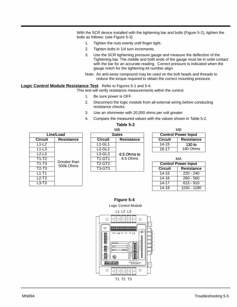
Troubleshooting 5-5MN894
With the SCR device installed with the tightening bar and bolts (Figure 5-2), tighten thebolts as follows: (see Figure 5-3)
1. Tighten the nuts evenly until finger tight.
2. Tighten bolts in 1/4 turn increments.
3. Use the SCR tightening pressure gauge and measure the deflection of theTightening bar. The middle and both ends of the gauge must be in solid contactwith the bar for an accurate reading. Correct pressure is indicated when thegauge notch for the tightening kit number align.
Note: An anti-seize compound may be used on the bolt heads and threads toreduce the torque required to obtain the correct mounting pressure.
Logic Control Module Resistance Test Refer to Figures 5-1 and 5-4.This test will verify resistance measurements within the control.
1. Be sure power is OFF.
2. Disconnect the logic module from all external wiring before conductingresistance checks.
3. Use an ohmmeter with 20,000 ohms per volt greater.
4. Compare the measured values with the values shown in Table 5-2.
Table 5-2MB MB
Line/Load Gates Control Power InputCircuit Resistance Circuit Resistance Circuit ResistanceL1-L2 L1-GL1 14-15 130 toL1-L3 L2-GL2 16-17
130 to180 Ohms
L2-L3 L3-GL3 6.5 Ohms toT1-T2 T1-GT1
6.5 Ohms to8.5 Ohms MA
T1-T3 Greater than T2-GT2 Control Power InputT2-T3
500k OhmsT3-GT3 Circuit Resistance
L1-T1 14-15 220 - 240L2-T2 14-16 260 - 560L3-T3 14-17 615 - 910
14-18 1150 - 1180
Figure 5-4
L1 L2 L3
T1 T2 T3
Logic Control Module

5-6 Troubleshooting MN894
Table 5-3 Troubleshooting Chart
Symptom Cause Corrective ActionMotor is not connected. Connect motor to T1, T2 and T3 of control.
MCP trips as it is ST contact on control is always closed. Repair or replace logic control module.MCP trips as it isclosed (also see Improper input voltage. Obtain the correct source voltage at L1, L2 and L3.closed (also seeShunt Trip light Shorted SCR. Replace SCR or power cell.comes ON) Control transformer (if equipped) set for wrong
voltage.Change tap connections for correct voltage.
MCP trip setting is too low. Increase MCP Trip setting.MCP trips as the Line voltage decreases during motor starting. Fix incoming power problem.motor is started Motor or wiring is defective. Check terminal and motor wiring.(also see Shunt Capacitors on output of control. Remove capacitors or move to line side of control.Trip light comesON) Logic control module is defective. Replace logic control module.ON)
Improper current calibration. Verify S1 settings for motor nameplate FLA rating.MCP trips after PF set too high. Reduce PF adjustment (rotate CCW).the motor is Occasional line imbalance. Set S2-6 =ON to disable shunt trip while running.running (also seeShunt Trip light Ground or motor fault. Check motor wiring.Shunt Trip lightcomes ON) S2-6=ON but no bypass contactor is installed. Check setting of S2-6. Should be Off.
No line voltage. Restore line voltage.Starter does Overload is open. Reset overload.nothing when No contact closure across terminals 12 and 13. Check start circuit.start button is Current trip occurs. Check S1 settings for correct current calibration.pressed.
Control module has no power. Check control transformer jumper.Control does not CL set too low. Increase CL adjustment (rotate CW).accelerate motorto full speed(Stalls)
Line voltage decreases to less than minimumoperating voltage during motor starting.
Fix incoming power regulation problem.
Insufficient torque Improper current feedback. Verify S1 settings for motor nameplate FLA rating.available fromcurrent limit CL.
CL set too low. Increase CL adjustment (rotate CW).
Motor Ramp up (RU) time set too long. Decrease RU (rotate CCW).accelerates tooslowly.
Improper current feedback. Verify S1 settings for motor nameplate FLA rating.
Current limit (CL) set too high. Reduce CL (rotate CCW).Ramp up time (RU) set too short. Increase RU (rotate CW).Initial pulse time (PT) set too long. Reduce PT (rotate CCW).MotorImproper current feedback. Verify S1 settings for motor nameplate FLA rating.accelerates too
quickly. Light or no load (is dependent on motor load).A lightly loaded motor will reach full speed withlow starting current or voltage. Motor mayrequire the use of a tachometer.
Decrease TU, increase RU or install tachometer.
Motor currentand voltageoscillates afterstart
Power factor correction set too high. Reduce PF setting (rotate CCW) until oscillationstops.
Line voltage decreases to less than minimumoperating voltage during motor starting.
Fix incoming power regulation problem.
Single phasing due to an open phase. Check wiring and overload heaters.Motor is noisy orvibrates when
Single phasing or unbalanced current due to anon-firing SCR.
Check for shorted SCR and replace.
startingSingle phasing or unbalanced current due to adefective logic control module.
Repair or replace the logic control module.
Defective motor. Check motor for shorts, opens or grounds.
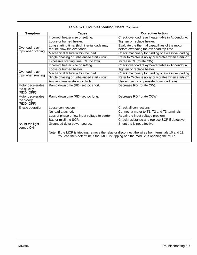
Troubleshooting 5-7MN894
Table 5-3 Troubleshooting Chart Continued
Symptom Cause Corrective ActionIncorrect heater size or setting. Check overload relay heater table in Appendix A.Loose or burned heater. Tighten or replace heater.
Overload relayLong starting time. (high inertia loads mayrequire slow trip overloads.
Evaluate the thermal capabilities of the motorbefore extending the overload trip time.
trips when startingMechanical failure within the load. Check machinery for binding or excessive loading.Single phasing or unbalanced start circuit. Refer to “Motor is noisy or vibrates when starting”.Excessive starting time (CL too low). Increase CL (rotate CW).Incorrect heater size or setting. Check overload relay heater table in Appendix A.Loose or burned heater. Tighten or replace heater.
Overload relay Mechanical failure within the load. Check machinery for binding or excessive loading.trips when running
Single phasing or unbalanced start circuit. Refer to “Motor is noisy or vibrates when starting”.Ambient temperature too high. Use ambient compensated overload relay.
Motor deceleratestoo quickly(RDD=OFF)
Ramp down time (RD) set too short. Decrease RD (rotate CW).
Motor deceleratestoo slowly(RDD=OFF)
Ramp down time (RD) set too long. Decrease RD (rotate CCW).
Erratic operation Loose connections. Check all connections.No load attached. Connect a motor to T1, T2 and T3 terminals.Loss of phase or low input voltage to starter. Repair the input voltage problem.Bad or misfiring SCR. Check resistance and replace SCR if defective.
Shunt trip light Grounded delta power source. Shunt trip is not effective.Shunt trip lightcomes ON
Note: If the MCP is tripping, remove the relay or disconnect the wires from terminals 10 and 11.You can then determine if the MCP is tripping or if the module is opening the MCP.

5-8 Troubleshooting MN894
The control panel is intended to provide years of trouble free service with appropriatecooling and protection from the elements. Should trouble occur, refer to the appropriatecontrol manual for control and motor troubleshooting information.
Reset the Circuit Breaker If the circuit breaker is tripped, it must be reset to restore power. The breaker is tripped ifthe handle is in the “Tripped” position as indicated in Figure 5-5.
Before the breaker is reset, locate the source of electrical trouble.
1. Check for phase-to-phase and phase-to-ground shorts.
2. Check for loose connections at power connectors (L1, L2, L3 and Earth as wellas T1, T2, T3 and Motor Ground).
3. If all checks in steps 1 and 2 are OK, move the breaker handle all the way downto the “Reset” position then move the handle to the “ON” position to restorepower. (In the “Reset” position, a click sound will be heard.)
4. Verify that an overcurrent condition is tripping the circuit breaker (not a shunttrip). If the circuit breaker shunt trip was energized, the trip was caused by theLCM soft start module shunt trip feature. Eliminate the cause of the shunt trip.
Figure 5-5 Magnetic Circuit Breaker
ON
Tripped
OFFReset
Handle
Rating PlugTrip Level
Manual TripShunt Trip Device
Shunt Trip Wires toLCM soft start module

Troubleshooting 5-9MN894
Reset an Overload Relay If the Overload relay is tripped, the tripped indicator (Reset Button of Figure 5-6) will be inthe “Tripped” position.
1. Verify that the overload condition has been cleared to allow restart.
2. Verify motor lead connections are tight.
3. Allow time for the overload to cool.
4. Press the “Reset Button” (Figure 5-6).
Figure 5-6 Overload Relay
ResetButton
ResetButton
Fuse Replacement If the control circuit voltage drops to zero volts, the control power transformer fuses(Figure 5-7) should be inspected. If a fuse is opened, perform the following steps:
1. Check for line-to-ground short circuit condition and repair if necessary.
2. Check control wiring and control devices (timers, relays, terminal blocks, wireterminations, etc.) for signs of damage, overheating, or loose connections andrepair if necessary.
3. Replace the fuse with the same fuse class, type, rating and interruptingcapacity.
Figure 5-7 Control Transformer with Fuses

5-10 Troubleshooting MN894

Section 6Specifications and Product Data
Specifications and Product Data 6-1MN894
IdentificationThree Phase Starters
Control TypeM- Multipurpose
M B
Control GroupA - Self powered logic control moduleB - Logic control modules that require
115 or 230VAC.
Input Voltage Code 7- 208/230/460VAC (60Hz)
8- 230/460/575VAC (60Hz)MA9- 220/380/415 (50Hz)MB9- 380/400/415VAC (50Hz)
7 – 030 –
Ampere Rating 008- 8 Amp016- 16 Amp030- 30 Amp055- 55 Amp080- 80 Amp160- 160 Amp250- 250 Amp420- 420 Amp600- 600 Amp840- 840 Amp
C B
Bypass Contactor0 – Normally not shown unless a
reduced size bypass is used.A – First size smaller bypass.B – Second size smaller bypass.C – Third size smaller bypass.
EnclosureA- OpenB- NEMA1 (IP32)C- NEMA12 (IP65)P- Panel Mount
ConfigurationA - Combination with overload & circuit
breaker).B - Non-combination (with overload).C - Starter only.D - Combination with fuse disconnect.G - Bypass, combination starter.H - Bypass, non-combination starter.J - Bypass, starter only.K - Bypass combination starter with
fuse disconnect.
– * *
Disconnect Size0 – Normally not shown unless a
reduced size disconnect is used.1 – Reduced size disconnect used:
i.e. 800 amp breaker on a 840ampcontrol instead of a 1000 ampbreaker.

6-2 Specifications and Product Data MN894
Multipurpose Control SpecificationsThree Phase Starters
����������
������� ������� ��������������
������� ������� ���������
�������� �� � �� � �� �
��� � � ��
��� � � �� �� �� ��
��� � �� ��
����������
������� ������� ������� ������� ������� ������� ��������������
������� ������� ������� ������� ������� ������� ���������
�������� �� � �� � �� � �� � �� � �� � �� �
��� �� �� �� �� ��� ���
��� ����
����
�����
������
������
������
������
��� ����
����
������
������
������
������
������
��� �� �� ��� ��� ��� ��� ���
� = Continuous Current Rating
Input Ratings
Input Frequency 60/50 HZ ± 5%
Input Voltage +10% to –15% of Voltage Rating (except 575 VAC, max= 620VAC)
Overload Rating Continuous 115% of FLA; 400% for 30 seconds.
Phase Three Phase
Duty Continuous
Storage Conditions
Ambient Temperature: -4 to 140°F (-20 to 60 °C)
Humidity: 0 - 95% RH Non-Condensing
Operating Conditions
Enclosure: Open Panel (Indoor)JIC (Indoor)NEMA 1 (Industrial indoor, general purpose)NEMA 12 (Industrial indoor, dust proof)NEMA 4 (Outdoor)The SCR’s generate about 3.3 watts of heat per running amp (motor FLA). If the controlis mounted in an enclosure, the installer must provide fans or blower with sufficient ventila-tion. Fan or blower should be rated for at least 0.8 CFM per ampere of motor FLA rating.Baldor provided enclosures are designed to dissipate the heat from the SCR’s.
Humidity: 0 - 95% RH Non-Condensing
Control Heat Loss 3.3 Watt per running ampere of input current
Ambient Operating Temperature: 32-113°F (0 to +45 °C) enclosed32-122°F (0 to +50 °C) open panel
Altitude: Sea level to 3300 Feet (1000 Meters)Derate 1% per 330 Feet (100 Meters) above 3300 Feet
Derating Derate Amp rating 1% per 330 Feet (100 Meters) above 3300 FeetDerate Amp rating 1.5% per °C over 45 °C to 55 °C Max

Specifications and Product Data 6-3MN894
Control Specifications
Control Method 6 SCR’s connected in inverse parallel for full-wave 3 phase control
Peak Inverse Voltage 208/230 460 575
1200VAC minimum 1200VAC minimum 1600VAC
Start Time Adjustable range 3-50 seconds (current limit starting is not timed).
Stop Time Adjustable range 5-50 seconds (can only extend stop time).
Initial Torque Adjustable range: Starting 40-75%, Stopping 0-100%.
Current Limit (Selectable) Adjustable range 75-400% of FLA (full load amperes).
Pulse Time (Selectable) Adjustable range 0.1-1.5 seconds.
Current Monitor (Selectable) Adjustable range 50-400% of FLA. Causes contact closure or control shutdown when current level is reached (after starting).
Power Factor Adjustable for maximum reduced motor voltage, dependent on load.
Tach input (Selectable) 0-10VDC (maximum 10msec response time from tach).
Control module power 12VA at 115/230VAC ±5%
Status Contacts 125VAC at 0.5A, normally open. 60VA maximum rating.
Agency Listings UL (Underwriters Laboratory) and cUL (Canada)
Rated Storage Temperature: –40 °F to +140 °F (– 40 °C to +60 °C)
Note: A minimum inductance of 0.01 Henry is require for the SCR’s to commutate. Some large horsepower motors maynot have enough inductance and require adding inductors between the motor and control.
SCR Specifications
Overcurrent Over current shut down at 450% of motor FLA nameplate rating.
Shorted SCR detection Shunt Trip contract.
Protective Features
Overload Electronic overload class 30.
SCR Thermostat Trips on overtemperature of heatsink (sizes 55 amps and larger only).
Phase Loss Shunt Trip contact (sizes 55 amps and larger only) active only at power-up.
Voltage Transient MOV (metal oxide varistor).
Indicator LEDs
Power ON Ramp End
Over Current Shunt Trip
Current Monitor Start/Run
Motor Power Motor Current
MOV Devices Four varistors connected in wye configuration with one to ground.
MOV505ELMax line volts=510VACWatts = 1.0Max one time surge of 6500A @ 8V/20�s
MOV620EMax line volts=625VACWatts = 1.0Max one time surge of 6500A @ 8V/20�s

6-4 Specifications and Product Data MN894
Wire Size & Tightening Torque Specifications
OR
(A)
(A)
(C)
(D)
(D)
(B)
(B)
(D)
(D)
GND
GND
8, 16 Amp Control OnlyCombination Starter and Non-Combination Starter
and Control Only
Line Input
Motor Output Load
GND
GND
Control Connections
Line Input
Motor Output Load
Control
TB1
(C)
Wire Size Torque Specifications Size 8,16
Terminal Amps Wire Size TorqueTerminal(Identifier)
Amps Wire SizeAWG
Torquelb-in
A 8, 16 10 - 16 20Note1: Refer to the label on the
B 30 8 - 18 35equipment panel for line andload tightening torque values.
55 4 Note 1load tightening torque values.
80 3 Note 1 Note2: Refer to the label on the
160 3/0 Note 1equipment panel for groundwire sizes.
250 350 KCMIL Note 1wire sizes.
420 (2) 300 KCMIL Note 1600 (2) 500 KCMIL Note 1840 (3) 500 KCMIL Note 1
C All 12 - 22 12D 8, 16, 30 6-14 45
55 Note 2 Note 180 Note 2 Note 1160 Note 2 Note 1250 Note 2 Note 1420 Note 2 Note 1600 Note 2 Note 1840 Note 2 Note 1

Specifications and Product Data 6-5MN894
Mounting DimensionsOpen Panel
A
Dia
B
w
h
d
Open/Panel DimensionsAmp Control Only Non-Combination Starter Combination Starter
Rating A B h w d Dia A B h w d Dia A B h w d Dia8 12.25 10.25 11.63 9.63 10.16 0.25 21.00 14.50 19.50 13.00 10.16 0.50 21.00 14.50 19.50 13.00 10.16 0.50
16 12.25 10.25 11.63 9.63 10.16 0.25 21.00 14.50 19.50 13.00 10.16 0.50 21.00 14.50 19.50 13.00 10.16 0.5030 12.25 10.25 11.63 9.63 10.16 0.25 21.00 14.50 19.50 13.00 10.16 0.50 21.00 14.50 19.50 13.00 10.16 0.5055 21.00 21.00 19.24 19.24 12.62 0.50 21.00 21.00 19.24 19.24 12.62 0.50 21.00 21.00 19.24 19.24 12.62 0.5080 21.00 21.00 19.24 19.24 12.62 0.50 21.00 21.00 19.24 19.24 12.62 0.50 21.00 21.00 19.24 19.24 12.62 0.50160 39.00 27.00 31.24 25.24 9.35 0.50 39.00 27.00 31.24 25.24 9.35 0.50 39.00 27.00 31.24 25.24 9.35 0.50250 39.00 27.00 31.24 25.24 11.35 0.50 39.00 27.00 31.24 25.24 11.35 0.50 39.00 27.00 31.24 25.24 11.35 0.50420 45.00 33.00 43.24 31.24 13.35 0.50 45.00 33.00 43.24 31.24 13.35 0.50 45.00 33.00 43.24 31.24 13.35 0.50600 57.00 33.00 55.24 31.24 13.35 0.50 57.00 33.00 55.24 31.24 13.35 0.50 57.00 33.00 55.24 31.24 13.35 0.50840 57.00 33.00 55.24 31.24 13.35 0.50 57.00 33.00 55.24 31.24 13.35 0.50 57.00 33.00 55.24 31.24 13.35 0.50
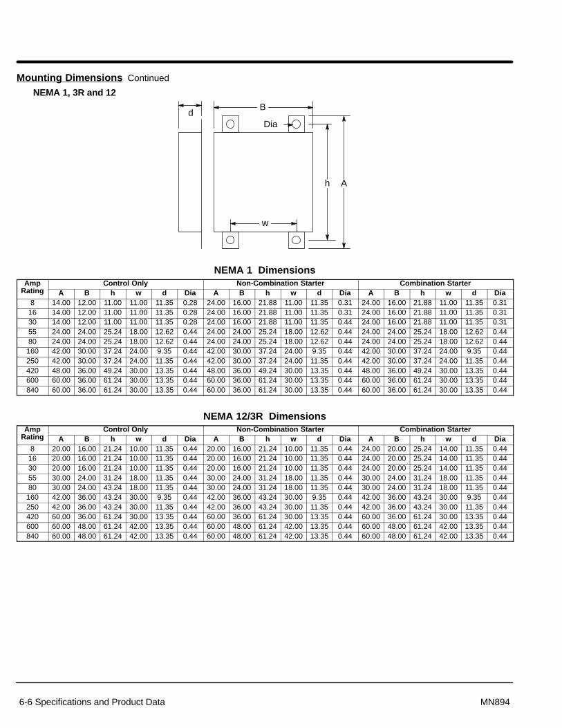
6-6 Specifications and Product Data MN894
Mounting Dimensions Continued
NEMA 1, 3R and 12
A
Dia
B
w
h
d
NEMA 1 DimensionsAmp Control Only Non-Combination Starter Combination Starter
Rating A B h w d Dia A B h w d Dia A B h w d Dia8 14.00 12.00 11.00 11.00 11.35 0.28 24.00 16.00 21.88 11.00 11.35 0.31 24.00 16.00 21.88 11.00 11.35 0.31
16 14.00 12.00 11.00 11.00 11.35 0.28 24.00 16.00 21.88 11.00 11.35 0.31 24.00 16.00 21.88 11.00 11.35 0.3130 14.00 12.00 11.00 11.00 11.35 0.28 24.00 16.00 21.88 11.00 11.35 0.44 24.00 16.00 21.88 11.00 11.35 0.3155 24.00 24.00 25.24 18.00 12.62 0.44 24.00 24.00 25.24 18.00 12.62 0.44 24.00 24.00 25.24 18.00 12.62 0.4480 24.00 24.00 25.24 18.00 12.62 0.44 24.00 24.00 25.24 18.00 12.62 0.44 24.00 24.00 25.24 18.00 12.62 0.44160 42.00 30.00 37.24 24.00 9.35 0.44 42.00 30.00 37.24 24.00 9.35 0.44 42.00 30.00 37.24 24.00 9.35 0.44250 42.00 30.00 37.24 24.00 11.35 0.44 42.00 30.00 37.24 24.00 11.35 0.44 42.00 30.00 37.24 24.00 11.35 0.44420 48.00 36.00 49.24 30.00 13.35 0.44 48.00 36.00 49.24 30.00 13.35 0.44 48.00 36.00 49.24 30.00 13.35 0.44600 60.00 36.00 61.24 30.00 13.35 0.44 60.00 36.00 61.24 30.00 13.35 0.44 60.00 36.00 61.24 30.00 13.35 0.44840 60.00 36.00 61.24 30.00 13.35 0.44 60.00 36.00 61.24 30.00 13.35 0.44 60.00 36.00 61.24 30.00 13.35 0.44
NEMA 12/3R DimensionsAmp Control Only Non-Combination Starter Combination Starter
Rating A B h w d Dia A B h w d Dia A B h w d Dia8 20.00 16.00 21.24 10.00 11.35 0.44 20.00 16.00 21.24 10.00 11.35 0.44 24.00 20.00 25.24 14.00 11.35 0.44
16 20.00 16.00 21.24 10.00 11.35 0.44 20.00 16.00 21.24 10.00 11.35 0.44 24.00 20.00 25.24 14.00 11.35 0.4430 20.00 16.00 21.24 10.00 11.35 0.44 20.00 16.00 21.24 10.00 11.35 0.44 24.00 20.00 25.24 14.00 11.35 0.4455 30.00 24.00 31.24 18.00 11.35 0.44 30.00 24.00 31.24 18.00 11.35 0.44 30.00 24.00 31.24 18.00 11.35 0.4480 30.00 24.00 43.24 18.00 11.35 0.44 30.00 24.00 31.24 18.00 11.35 0.44 30.00 24.00 31.24 18.00 11.35 0.44160 42.00 36.00 43.24 30.00 9.35 0.44 42.00 36.00 43.24 30.00 9.35 0.44 42.00 36.00 43.24 30.00 9.35 0.44250 42.00 36.00 43.24 30.00 11.35 0.44 42.00 36.00 43.24 30.00 11.35 0.44 42.00 36.00 43.24 30.00 11.35 0.44420 60.00 36.00 61.24 30.00 13.35 0.44 60.00 36.00 61.24 30.00 13.35 0.44 60.00 36.00 61.24 30.00 13.35 0.44600 60.00 48.00 61.24 42.00 13.35 0.44 60.00 48.00 61.24 42.00 13.35 0.44 60.00 48.00 61.24 42.00 13.35 0.44840 60.00 48.00 61.24 42.00 13.35 0.44 60.00 48.00 61.24 42.00 13.35 0.44 60.00 48.00 61.24 42.00 13.35 0.44
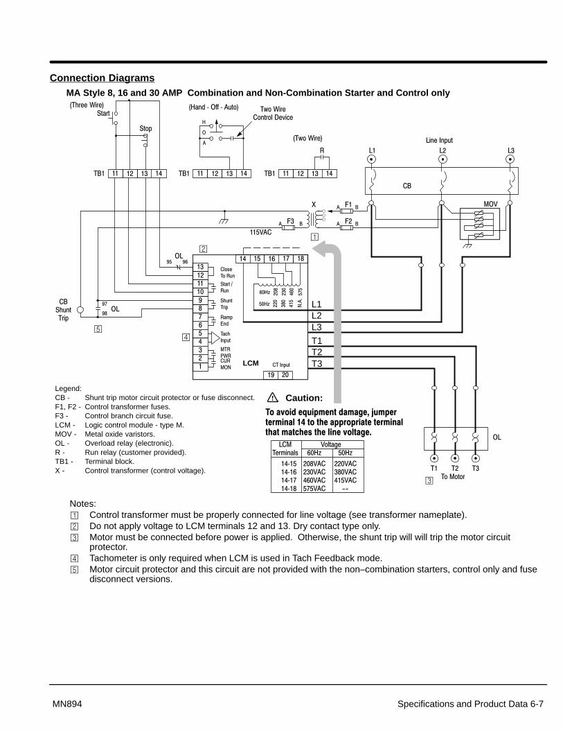
Specifications and Product Data 6-7MN894
Connection DiagramsMA Style 8, 16 and 30 AMP Combination and Non-Combination Starter and Control only
�����������������
�� ���� ��
�� ��
������ !�
"���# !�
"$!����%
�&% �'
��($)�%!
�� *+ �, ��� ���)�%!
�
�
�-��
��
�
�
.
������
� �/�
� /�
� /�
�
�
�� ������
�-����
�� �� ������
�-
��
-� -� -�
-����)�%!
���
"��
"%
0�$����+���1
2
�
�
�3�+��������4�5�(�
02��'����66����!1
LCM
Legend:CB - Shunt trip motor circuit protector or fuse disconnect.F1, F2 - Control transformer fuses.F3 - Control branch circuit fuse.LCM - Logic control module - type M.MOV - Metal oxide varistors.OL - Overload relay (electronic).R - Run relay (customer provided).TB1 - Terminal block.X - Control transformer (control voltage).
�� ��������� �� ���������
0�3�+���1
��
��"$!����%
L1L2L3
T1T2T3
�
-�����&����� ��27 ��27
��������������������
������������������������
������������������88
�������������������������������������������� �������������������� ����! �"�� ������������#
���9�
���
���
���
���
���
Caution:
��27
���
���
���
�:�:
��27
Notes:� Control transformer must be properly connected for line voltage (see transformer nameplate).� Do not apply voltage to LCM terminals 12 and 13. Dry contact type only.� Motor must be connected before power is applied. Otherwise, the shunt trip will will trip the motor circuit
protector.� Tachometer is only required when LCM is used in Tach Feedback mode.� Motor circuit protector and this circuit are not provided with the non–combination starters, control only and fuse
disconnect versions.

Section 1General Information
6-8 Specifications and Product Data MN894
Connection Diagrams Continued
MB Style 8, 16 and 30 AMP Combination and Non-Combination Starter and Control only
�����������������
�� ���� ��
�� ��
������ !�
"���# !�
"$!����%
�&% �'
��($)�%!
�� *+ �, ��� ���)�%!
�
�
�-��
��
�
�
.
������
� �/�
� /�
� /�
�
�
�� ������
�-����
�� �� ������
�-
��
-� -� -�
-����)�%!
���
0�$����+���1
2
�
�
�3�+��������4�5�(�
02��'����66����!1
LCM
Legend:CB - Shunt trip motor circuit protector or fuse disconnect.F1, F2 - Control transformer fuses.F3 - Control branch circuit fuse.LCM - Logic control module - type M.MOV - Metal oxide varistors.OL - Overload relay (electronic).R - Run relay (customer provided).TB1 - Terminal block.X - Control transformer (control voltage).
�� ��������� �� ���������
0�3�+���1
��"$!����%
L1L2L3
T1T2T3
�
���
"��
"%
Notes:� Control transformer must be properly connected for line voltage (see transformer nameplate).� Do not apply voltage to LCM terminals 12 and 13. Dry contact type only.� Motor must be connected before power is applied. Otherwise, the shunt trip will will trip the motor circuit
protector.� Tachometer is only required when LCM is used in Tach Feedback mode.� Motor circuit protector and this circuit are not provided with the non–combination starters, control only and fuse
disconnect versions.
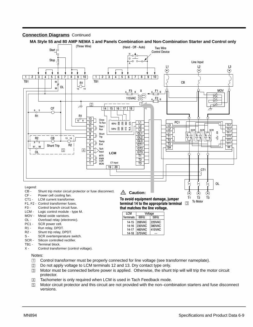
Section 1General Information
Specifications and Product Data 6-9MN894
Connection Diagrams Continued
MA Style 55 and 80 AMP NEMA 1 and Panels Combination and Non-Combination Starter and Control only
�����������������
�� ���� ��
-�-�-�;-�;-�;-�;��;��;��������
�� ��
������ !�
"���# !�
"$!����%
�&% �'
��($)�%!
�� *+ �, ��� ���)�%!
"$!�����%
�
� �
� ��
�-
�� �
�� ��
�
�
�
�� �
� �
�
�/
.
������
� �/� � /�
� /�
�
�
�
�� ��
� ��� ��� ��� �
�-��
��
������
-�-�-�
"�
;��
;��
;��
;-�
;-�
;-�
"�
*��
���
�� �� ������
�-
��
-� -� -�
-����)�%!
� ��� ��� ��� �
������
"��
"%
0�$����+���1
2
�
�
�3�+��������4�5�(�
02��'����66����!1
"� "� "�
LCM
Legend:CB - Shunt trip motor circuit protector or fuse disconnect.CF - Power cell cooling fan.CT1 - LCM current transformer.F1, F2 - Control transformer fuses.F3 - Control branch circuit fuse.LCM - Logic control module - type M.MOV - Metal oxide varistors.OL - Overload relay (electronic).PC1 - SCR power cell.R1 - Run relay, DPDT.R2 - Shunt trip relay, DPDT.S - SCR overtemperature switch.SCR - Silicon controlled rectifier.TB1 - Terminal block.X - Control transformer (control voltage).
"
�� ��
���
���
���
���
��27
���
���
���
�:�:
��27
��
-�����&����� ��27 ��27
��������������������
������������������������
������������������88
�������������������������������������������� �������������������� ����! �"�� ������������#
���9�
Caution:
���
Notes:� Control transformer must be properly connected for line voltage (see transformer nameplate).� Do not apply voltage to LCM terminals 12 and 13. Dry contact type only.� Motor must be connected before power is applied. Otherwise, the shunt trip will will trip the motor circuit
protector.� Tachometer is only required when LCM is used in Tach Feedback mode.� Motor circuit protector and this circuit are not provided with the non–combination starters and fuse disconnect
versions.

Section 1General Information
6-10 Specifications and Product Data MN894
Connection Diagrams Continued
MB Style 55 and 80 AMP NEMA 1 and Panels Combination and Non-Combination Starter and Control only
�����������������
�� ���� ��
-�-�-�;-�;-�;-�;��;��;��������
�� ��
������ !�
"���# !�
"$!����%
�&% �'
��($)�%!
�� *+ �, ��� ���)�%!
"$!�����%
�
� �
� ��
�-
�� �
�� ��
�
�
�
�� �
� �
�
�/
.
������
� �/� � /�
� /�
�
�
�
�� ��
� ��� ��� ��� �
�-��
��
������
-�-�-�
"�
;��
;��
;��
;-�
;-�
;-�
"�
*��
���
�� �� ������
�-
��
-� -� -�
-����)�%!
� ��� ��� ��� �
������
"��
"%
0�$����+���1
2
�
�
�3�+��������4�5�(�
02��'����66����!1
"� "� "�
LCM
Legend:CB - Shunt trip motor circuit protector or fuse disconnect.CF - Power cell cooling fan.CT1 - LCM current transformer.F1, F2 - Control transformer fuses.F3 - Control branch circuit fuse.LCM - Logic control module - type M.MOV - Metal oxide varistors.OL - Overload relay (electronic).PC1 - SCR power cell.R1 - Run relay, DPDT.R2 - Shunt trip relay, DPDT.S - SCR overtemperature switch.SCR - Silicon controlled rectifier.TB1 - Terminal block.X - Control transformer (control voltage).
"
�� ��
���
Notes:� Control transformer must be properly connected for line voltage (see transformer nameplate).� Do not apply voltage to LCM terminals 12 and 13. Dry contact type only.� Motor must be connected before power is applied. Otherwise, the shunt trip will will trip the motor circuit
protector.� Tachometer is only required when LCM is used in Tach Feedback mode.� Motor circuit protector and this circuit are not provided with the non–combination starters and fuse disconnect
versions.

Section 1General Information
Specifications and Product Data 6-11MN894
Connection Diagrams Continued
NEMA 1 & Panel Mounted Size 160–840 AMP Control Only
�����������������
�� ���� ��
-�-�-�;-�;-�;-�;��;��;��������
�� ��
������ !�
"���# !�
"$!����%
�&% �'
��($)�%!
�� *+ �, ��� ���)�%!
�
�
��
�
�� �
�
�
��/
.
������
� �/� � /�
� /�
�
�
�
�� ��
� ��� ��� ��� �
���
�� �� ��
����
-� -� -�
-����)�%!
� ��� ��� ��� �
���
���
"��
"%
0�$����+���12
�
�
�3�+��������4�5�(�
02��'����66����!1
LCM
Legend:CF - Power cell cooling fan.CS - Snubber capacitor.CT1 - LCM current transformer.CT2 - Primary current transformer.F1, F2 - Control transformer fuses.F3 - Control branch circuit fuse.LCM - Logic control module - type M.M -MOV - Metal oxide varistors.
�/
�/
�(��!��/��
���
��
��.����<����!�����.����<����!�����.����<����!�����.����<����!�����.����<����!���
�
-;-;�
"�
*��
"�
"�
"
-���
-�'
"
-�
;-�
;��
��
"�
"�
�
-;-;�
"�
*��
"�
"�
"
-���
-�'
"
-�
;-�
;��
��
"�
"�
�
-;-;�
"�
*��
"�
"�
"
-���
-�'
"
-�
;-�
;��
��
"�
"�
*��#-
*��#-
*��#-
*��#;-
*��#;-
*��#;-
*��#;�
*��#;�
*��#;�
*��#�
*��#�
*��#�
�-
�(��!��/��
�-
� ��� ��� ��� �
���
������-����"������������(!� �(��!��
/��
�-
�
0-����"3�($�'1
OL - Overload relay (electronic).PC1,2,3 - SCR power cells.R1 - Run relay, DPDT.RS - Snubber resistor.S - SCR overtemperature switch.SCR - Silicon controlled rectifier.TB1 - Terminal block.X - Control transformer (control voltage).
�
�
���
Notes:� Control transformer must be properly connected for line voltage (see transformer nameplate).� Do not apply voltage to LCM terminals 12 and 13. Dry contact type only.� Number of cooling fans depends on the FLA rating.� Tachometer is only required when LCM is used in Tach Feedback mode.� MOVs are connected in parallel for greater energy absorption for control sizes above 420Amp FLA.� LCM voltage jumper must be positioned for the proper voltage (LCM Term 14 – 18, see table). For factory supplied enclosure fans only.
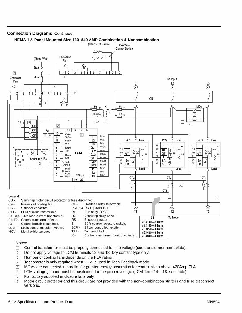
Section 1General Information
6-12 Specifications and Product Data MN894
Connection Diagrams Continued
NEMA 1 & Panel Mounted Size 160–840 AMP Combination & Noncombination
�����������������
�� ���� ��
-�-�-�;-�;-�;-�;��;��;��������
�� ��
������ !�
"���# !�
"$!����%
�&% �'
��($)�%!
�� *+ �, ��� ���)�%!
�
�
��
�
�� �
�
�
��/
.
������
� �/� � /�
� /�
�
�
�
�� ��
� ��� ��� ��� �
���
�� �� ��
����
�-
��
-� -� -�
-����)�%!
� ��� ��� ��� �
���
���
"��
"%
0�$����+���1
2
�
�
�3�+��������4�5�(�
02��'����66����!1
LCM
Legend:CB - Shunt trip motor circuit protector or fuse disconnect..CF - Power cell cooling fan.CS - Snubber capacitor.CT1 - LCM current transformer.CT2,3,4 - Overload current transformer.F1, F2 - Control transformer fuses.F3 - Control branch circuit fuse.LCM - Logic control module - type M.MOV - Metal oxide varistors.
�/
�/
�(��!��/��
���
�
-;-;�
"�
*��
"�
"�
"
-���
-�'
"
-�
;-�
;��
��
"�
"�
�
-;-;�
"�
*��
"�
"�
"
-���
-�'
"
-�
;-�
;��
��
"�
"�
�
-;-;�
"�
*��
"�
"�
"
-���
-�'
"
-�
;-�
;��
��
"�
"�
*��#-
*��#-
*��#-
*��#;-
*��#;-
*��#;-
*��#;�
*��#;�
*��#;�
*��#�
*��#�
*��#�
�(��!��/��
�-
OL - Overload relay (electronic).PC1,2,3 - SCR power cells.R1 - Run relay, DPDT.R2 - Shunt trip relay, DPDT.RS - Snubber resistor.S - SCR overtemperature switch.SCR - Silicon controlled rectifier.TB1 - Terminal block.X - Control transformer (control voltage).
�
�
�-��
��
"$!�����%
�
� ��
�-
�� �
�� ��
�� ��
��� ���
���
��
��.����<����!�����.����<����!�����.����<����!�����.����<����!�����.����<����!���
Notes:� Control transformer must be properly connected for line voltage (see transformer nameplate).� Do not apply voltage to LCM terminals 12 and 13. Dry contact type only.� Number of cooling fans depends on the FLA rating.� Tachometer is only required when LCM is used in Tach Feedback mode.� MOVs are connected in parallel for greater energy absorption for control sizes above 420Amp FLA.� LCM voltage jumper must be positioned for the proper voltage (LCM Term 14 – 18, see table). For factory supplied enclosure fans only. Motor circuit protector and this circuit are not provided with the non–combination starters and fuse disconnect
versions.

Section 1General Information
Specifications and Product Data 6-13MN894
Connection Diagrams Continued
NEMA 12 Size 160–840 AMP Combination & Noncombination Bypass
�����������������
�� ���� ��
-�-�-�;-�;-�;-�;��;��;��������
�� ��
������ !�
"���# !�
"$!����%
�&% �'
��($)�%!
�� *+ �, ��� ���)�%!
�
�
��
�
�� �
��
�
�/
.
������
� �/� � /�
� /�
�
�
�
�� ��
� ��� ��� ��� �
���
�� �� ��
����
��
-� -� -�
-����)�%!� ��� ��� ��� �
���
���
"��
"%
0�$����+���12
�
�
�3�+���������4�5�(�02��'����66����!1
LCM
Legend:BP - BYPASS Contactor.CB - Shunt trip motor circuit protector or fuse disconnect..CF - Power cell cooling fan.CS - Snubber capacitor.CT1 - LCM current transformer.CT2,3,4 - Overload current transformer.F1, F2 - Control transformer fuses.F3 - Control branch circuit fuse.LCM - Logic control module - type M.MOV - Metal oxide varistors.
�/
�/
�(��!��/��
���
�
-;-;�
"�
*��
"�
"�
"
-���
-�'
"
-�
;-�
;��
��
"�
"�
�
-;-;�
"�
*��
"�
"�
"
-���
-�'
"
-�
;-�
;��
��
"�
"�
�
-;-;�
"�
*��
"�
"�
"
-���
-�'
"
-�
;-�
;��
��
"�
"�
*��#-
*��#-
*��#-
*��#;-
*��#;-
*��#;-
*��#;�
*��#;�
*��#;�
*��#�
*��#�
*��#�
�(��!��/��
�-
OL - Overload relay (electronic).PC1,2,3 - SCR power cells.R1 - Run relay, DPDT.R2 - Shunt trip relay, DPDT.RS - Snubber resistor.S - SCR overtemperature switch.SCR - Silicon controlled rectifier.TB1 - Terminal block.X - Control transformer (control voltage).
�
�
�-��
��
"$!�����% �
� ��
�-
�� �
�� ��
�� ��
��� ���
�*
�-�-�-
� �*� �
�� ��
��� ��
���
��
��.����<����!�����.����<����!�����.����<����!�����.����<����!�����.����<����!���
Notes:� Control transformer must be properly connected for line voltage (see transformer nameplate).� Do not apply voltage to LCM terminals 12 and 13. Dry contact type only.� Number of cooling fans depends on the FLA rating.� Tachometer is only required when LCM is used in Tach Feedback mode.� MOVs are connected in parallel for greater energy absorption for control sizes above 420Amp FLA.� LCM voltage jumper must be positioned for the proper voltage (LCM Term 14 – 18, see table). For factory supplied enclosure fans only. Motor circuit protector and this circuit are not provided with the non–combination starters and fuse disconnect
versions. OL contact 97-98 not available with electronic overload relay.

Section 1General Information
6-14 Specifications and Product Data MN894
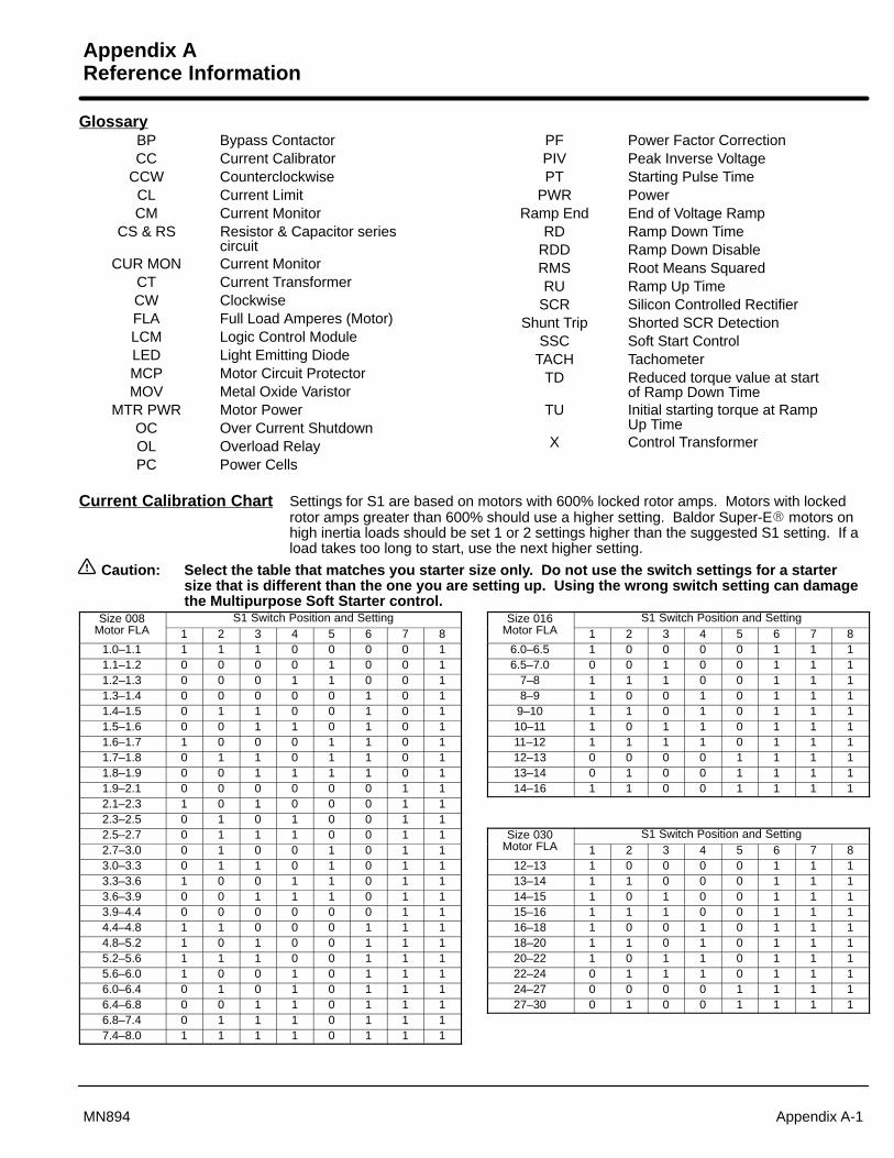
Appendix AReference Information
Appendix A-1MN894
GlossaryBP Bypass ContactorCC Current Calibrator
CCW CounterclockwiseCL Current LimitCM Current Monitor
CS & RS Resistor & Capacitor seriescircuit
CUR MON Current MonitorCT Current TransformerCW ClockwiseFLA Full Load Amperes (Motor)LCM Logic Control ModuleLED Light Emitting DiodeMCP Motor Circuit ProtectorMOV Metal Oxide Varistor
MTR PWR Motor PowerOC Over Current ShutdownOL Overload RelayPC Power Cells
PF Power Factor CorrectionPIV Peak Inverse VoltagePT Starting Pulse Time
PWR PowerRamp End End of Voltage Ramp
RD Ramp Down TimeRDD Ramp Down DisableRMS Root Means SquaredRU Ramp Up Time
SCR Silicon Controlled RectifierShunt Trip Shorted SCR Detection
SSC Soft Start ControlTACH Tachometer
TD Reduced torque value at startof Ramp Down Time
TU Initial starting torque at RampUp Time
X Control Transformer
Current Calibration Chart Settings for S1 are based on motors with 600% locked rotor amps. Motors with lockedrotor amps greater than 600% should use a higher setting. Baldor Super-E� motors onhigh inertia loads should be set 1 or 2 settings higher than the suggested S1 setting. If aload takes too long to start, use the next higher setting.
Caution: Select the table that matches you starter size only. Do not use the switch settings for a startersize that is different than the one you are setting up. Using the wrong switch setting can damagethe Multipurpose Soft Starter control.
Size 008 S1 Switch Position and SettingMotor FLA 1 2 3 4 5 6 7 8
1.0–1.1 1 1 1 0 0 0 0 11.1–1.2 0 0 0 0 1 0 0 11.2–1.3 0 0 0 1 1 0 0 11.3–1.4 0 0 0 0 0 1 0 11.4–1.5 0 1 1 0 0 1 0 11.5–1.6 0 0 1 1 0 1 0 11.6–1.7 1 0 0 0 1 1 0 11.7–1.8 0 1 1 0 1 1 0 11.8–1.9 0 0 1 1 1 1 0 11.9–2.1 0 0 0 0 0 0 1 12.1–2.3 1 0 1 0 0 0 1 12.3–2.5 0 1 0 1 0 0 1 12.5–2.7 0 1 1 1 0 0 1 12.7–3.0 0 1 0 0 1 0 1 13.0–3.3 0 1 1 0 1 0 1 13.3–3.6 1 0 0 1 1 0 1 13.6–3.9 0 0 1 1 1 0 1 13.9–4.4 0 0 0 0 0 0 1 14.4–4.8 1 1 0 0 0 1 1 14.8–5.2 1 0 1 0 0 1 1 15.2–5.6 1 1 1 0 0 1 1 15.6–6.0 1 0 0 1 0 1 1 16.0–6.4 0 1 0 1 0 1 1 16.4–6.8 0 0 1 1 0 1 1 16.8–7.4 0 1 1 1 0 1 1 17.4–8.0 1 1 1 1 0 1 1 1
Size 016 S1 Switch Position and SettingMotor FLA 1 2 3 4 5 6 7 8
6.0–6.5 1 0 0 0 0 1 1 16.5–7.0 0 0 1 0 0 1 1 1
7–8 1 1 1 0 0 1 1 18–9 1 0 0 1 0 1 1 1
9–10 1 1 0 1 0 1 1 110–11 1 0 1 1 0 1 1 111–12 1 1 1 1 0 1 1 112–13 0 0 0 0 1 1 1 113–14 0 1 0 0 1 1 1 114–16 1 1 0 0 1 1 1 1
Size 030 S1 Switch Position and SettingMotor FLA 1 2 3 4 5 6 7 8
12–13 1 0 0 0 0 1 1 113–14 1 1 0 0 0 1 1 114–15 1 0 1 0 0 1 1 115–16 1 1 1 0 0 1 1 116–18 1 0 0 1 0 1 1 118–20 1 1 0 1 0 1 1 120–22 1 0 1 1 0 1 1 122–24 0 1 1 1 0 1 1 124–27 0 0 0 0 1 1 1 127–30 0 1 0 0 1 1 1 1

A-2 Appendix MN894
Size 055 S1 Switch Position and SettingMotor FLA 1 2 3 4 5 6 7 8
24–26 0 1 0 0 0 1 1 127–30 1 0 1 0 0 1 1 131–34 0 0 0 1 0 1 1 135–38 0 1 0 1 0 1 1 139–42 0 0 1 1 0 1 1 143–45 0 1 1 1 0 1 1 146–48 1 1 1 1 0 1 1 149–51 0 0 0 0 1 1 1 152–55 1 0 0 0 1 1 1 1
Size 080 S1 Switch Position and SettingMotor FLA 1 2 3 4 5 6 7 8
44–46 0 1 1 1 0 1 1 147–52 0 0 0 0 1 1 1 153–58 1 0 0 0 1 1 1 159–64 1 1 0 0 1 1 1 165–69 0 0 1 0 1 1 1 170–75 1 0 1 0 1 1 1 176–80 0 1 1 0 1 1 1 1
Size 140 S1 Switch Position and SettingMotor FLA 1 2 3 4 5 6 7 8
58–63 0 1 0 0 0 1 1 064–70 1 0 0 0 1 1 1 071–78 1 1 1 1 1 1 1 079–86 0 0 1 1 0 0 0 187–95 0 1 1 0 1 0 0 1
96–105 0 0 0 0 0 1 0 1106–120 1 1 0 1 0 1 0 1121–128 1 0 0 0 1 1 0 1129–140 0 0 0 1 1 1 0 1
Size 160 S1 Switch Position and SettingMotor FLA 1 2 3 4 5 6 7 8
65–70 1 0 0 0 1 1 1 071–78 1 1 1 1 1 1 1 079–87 0 0 1 1 0 0 0 188–97 1 1 1 0 1 0 0 1
98–108 0 1 0 0 0 1 0 1109–120 1 1 0 1 0 1 0 1121–135 0 0 1 0 1 1 0 1136–148 1 1 0 1 1 1 0 1149–160 1 0 0 0 0 0 1 1
Size 250 S1 Switch Position and SettingMotor FLA 1 2 3 4 5 6 7 8108–113 1 1 0 0 1 0 1 0114–127 0 1 0 0 0 1 1 0128–144 0 0 1 0 1 1 1 0145–161 1 1 0 0 0 0 0 1162–180 0 0 0 0 1 0 0 1181–201 1 1 0 1 1 0 0 1202–224 0 1 1 0 0 1 0 1225–250 0 0 0 0 1 1 0 1
Size 420 S1 Switch Position and SettingMotor FLA 1 2 3 4 5 6 7 8200–214 1 1 0 0 0 1 0 1215–234 0 1 0 1 0 1 0 1235–249 1 0 0 0 1 1 0 1250–274 1 1 1 0 1 1 0 1275–299 0 0 1 1 1 1 0 1300–329 1 1 0 0 0 0 1 1330–361 0 0 0 1 0 0 1 1362–390 0 0 1 1 0 0 1 1391–420 0 0 0 0 1 0 1 1
Size 600 S1 Switch Position and SettingMotor FLA 1 2 3 4 5 6 7 8320–340 1 1 0 1 0 0 0 1341–360 0 1 0 0 1 0 0 1361–390 0 1 0 1 1 0 0 1391–430 1 1 0 0 0 1 0 1431–470 1 1 0 1 0 1 0 1471–520 0 1 0 0 1 1 0 1521–570 1 0 0 1 1 1 0 1571–600 1 1 1 1 1 1 0 1
Size 840 S1 Switch Position and SettingMotor FLA 1 2 3 4 5 6 7 8471–520 0 1 0 0 1 1 0 1521–570 1 0 0 1 1 1 0 1571–630 1 1 1 1 1 1 0 1631–690 0 1 1 0 0 0 1 1691–740 1 0 0 1 0 0 1 1741–800 1 0 1 1 0 0 1 1801–840 0 0 0 0 1 0 1 1

Appendix A-3MN894
Quick Reference Chart
Ramp Up Time (3-50 sec.)Tachometer: Time to reach full speed.Voltage: Time to reach full speed.
Torque Up (40-75% voltage)Tachometer: Disabled.Voltage: Initial starting voltage for ramp.
Current Limit (75-400% FLA)Tachometer or voltage: Enabled by S2-5=ON. Maximum current during ramp up and ramp down.
Pulse Time (0-1.5 sec.)Tachometer: Disabled.Voltage: Duration of 400% FLA starting pulse.
Ramp Down Time (5-50 sec.) – (Disabled with S2-1=ON)Tachometer: Time to reach zero speed.Voltage: Time to reach zero speed.
Torque Down Advance (0-100%) – (Disabled with S2-1=ON)Tachometer or voltage: Percentage reduction from full motor voltage for starting ramp down to zero volts.
Current Monitor (50-400% FLA) Enabled at end of start cycle.S2-2=ON: If motor current exceeds CM value, control will shutdown, CUR MON contact will close and
CUR MON light is ON.S2-2=OFF: Control will not shutdown, contact
will close, LED is ON.
Power Factor (0-100%)0 to maximum allowable motor voltage reduction to improve power factor.
Power applied to control.
Overcurrent shut down(450% FLA)
S1 Current Calibration and “Motor Current” bar graph. S1 selects 255 calibration points for motor FLA. See “Current Calibration Chart” in this section for the proper setting.
Bar Graph, displays the value of motor current during operation.
BP: S2-6, Bypass contactor enable.ON Shunt trip circuit is disabled during full on condition for bypass contactor to be used.OFF Shunt trip circuit is enabled in all conditions.
CL: S2-5, Current Limit enable.ON Current will not exceed Current Limit adjustment during ramp up and down except during pulse start.OFF Current Limit adjustment has no effect.
TACH: S2-4, Tachometer input enable.ON Control is in tachometer feedback ramp mode.OFF Control is in voltage ramp mode.
OC: S2-3, Over current shut down.ON Overcurrent shutdown will turn on CUR MON light and close the CUR MON contact.OFF Overcurrent shutdown will disable control with no affect to CUR MON light and contact.
CM: S2-2, Current Monitor Trip.ON Control will disable and CUR MON light and contact will indicate an overcurrent condition.OFF CUR MON light and contact will indicate an overcurrent condition.
RDD: S2-1, Ramp Down Disable.ON Control is immediately disabled when the “Close to Run” input is opened.OFF Control will ramp down when the “Close to Run” input is opened.
CUR MON: Indicates CM or CL have been exceeded.MTR PWR: Indicates voltage is applied to motor
during start, run & ramp down.TACH: Tachometer input (0-10VDC).RAMP END: End of start ramp (full run condition).SHUNT TRIP: Shunt trip due to shorted SCR.START/RUN: Confirm Close to Run contact is closed.CLOSE TO RUN: Start contact is closed.
CURMON
MTRPWR TACH
RAMPEND
SHUNTTRIP
START/RUN
CLOSETO RUN
��
��
�
�
�
�
�
�
�
��
�
�
��
��
�
�
��
�
�
��
�
�
�
�
�
�
�
�
�� �
�� ��
�� ���
� �:�
�� �
� ���
�� ���
� ���
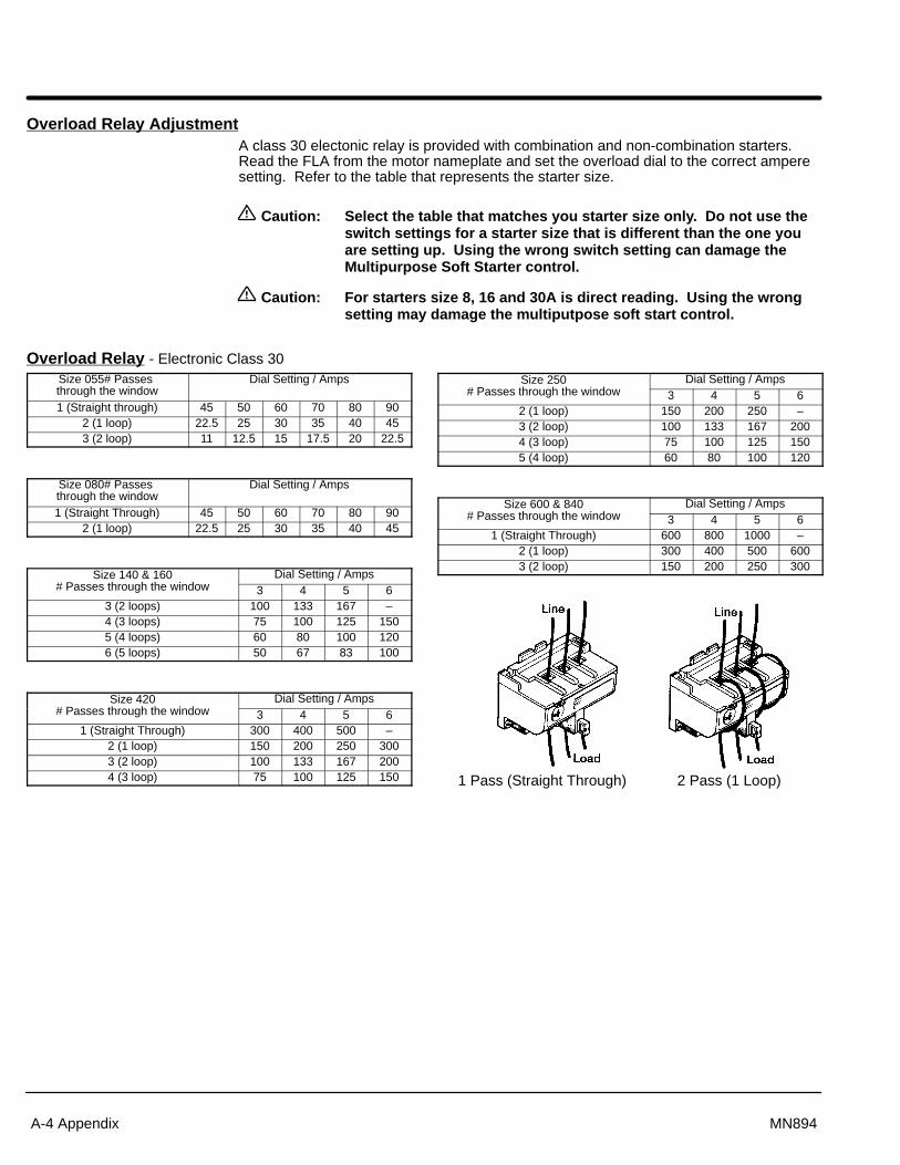
A-4 Appendix MN894
Overload Relay AdjustmentA class 30 electonic relay is provided with combination and non-combination starters.Read the FLA from the motor nameplate and set the overload dial to the correct amperesetting. Refer to the table that represents the starter size.
Caution: Select the table that matches you starter size only. Do not use theswitch settings for a starter size that is different than the one youare setting up. Using the wrong switch setting can damage theMultipurpose Soft Starter control.
Caution: For starters size 8, 16 and 30A is direct reading. Using the wrongsetting may damage the multiputpose soft start control.
Overload Relay - Electronic Class 30Size 055# Passes through the window
Dial Setting / Amps
1 (Straight through) 45 50 60 70 80 902 (1 loop) 22.5 25 30 35 40 453 (2 loop) 11 12.5 15 17.5 20 22.5
Size 080# Passes through the window
Dial Setting / Amps
1 (Straight Through) 45 50 60 70 80 902 (1 loop) 22.5 25 30 35 40 45
Size 140 & 160 Dial Setting / Amps# Passes through the window 3 4 5 6
3 (2 loops) 100 133 167 –4 (3 loops) 75 100 125 1505 (4 loops) 60 80 100 1206 (5 loops) 50 67 83 100
Size 420 Dial Setting / Amps# Passes through the window 3 4 5 6
1 (Straight Through) 300 400 500 –2 (1 loop) 150 200 250 3003 (2 loop) 100 133 167 2004 (3 loop) 75 100 125 150
Size 250 Dial Setting / Amps# Passes through the window 3 4 5 6
2 (1 loop) 150 200 250 –3 (2 loop) 100 133 167 2004 (3 loop) 75 100 125 1505 (4 loop) 60 80 100 120
Size 600 & 840 Dial Setting / Amps# Passes through the window 3 4 5 6
1 (Straight Through) 600 800 1000 –2 (1 loop) 300 400 500 6003 (2 loop) 150 200 250 300
1 Pass (Straight Through) 2 Pass (1 Loop)
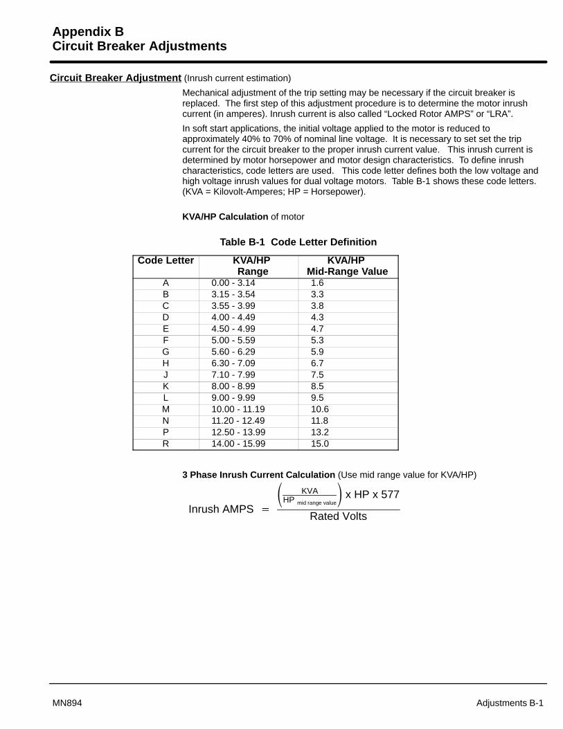
Appendix BCircuit Breaker Adjustments
Adjustments B-1MN894
Circuit Breaker Adjustment (Inrush current estimation)
Mechanical adjustment of the trip setting may be necessary if the circuit breaker isreplaced. The first step of this adjustment procedure is to determine the motor inrushcurrent (in amperes). Inrush current is also called “Locked Rotor AMPS” or “LRA”.
In soft start applications, the initial voltage applied to the motor is reduced toapproximately 40% to 70% of nominal line voltage. It is necessary to set set the tripcurrent for the circuit breaker to the proper inrush current value. This inrush current isdetermined by motor horsepower and motor design characteristics. To define inrushcharacteristics, code letters are used. This code letter defines both the low voltage andhigh voltage inrush values for dual voltage motors. Table B-1 shows these code letters. (KVA = Kilovolt-Amperes; HP = Horsepower).
KVA/HP Calculation of motor
Table B-1 Code Letter Definition
Code Letter KVA/HP Range
KVA/HP Mid-Range Value
A 0.00 - 3.14 1.6B 3.15 - 3.54 3.3C 3.55 - 3.99 3.8D 4.00 - 4.49 4.3E 4.50 - 4.99 4.7F 5.00 - 5.59 5.3G 5.60 - 6.29 5.9H 6.30 - 7.09 6.7J 7.10 - 7.99 7.5K 8.00 - 8.99 8.5L 9.00 - 9.99 9.5M 10.00 - 11.19 10.6N 11.20 - 12.49 11.8P 12.50 - 13.99 13.2R 14.00 - 15.99 15.0
3 Phase Inrush Current Calculation (Use mid range value for KVA/HP)
Inrush AMPS �
� KVAHP mid range value
� x HP x 577
Rated Volts
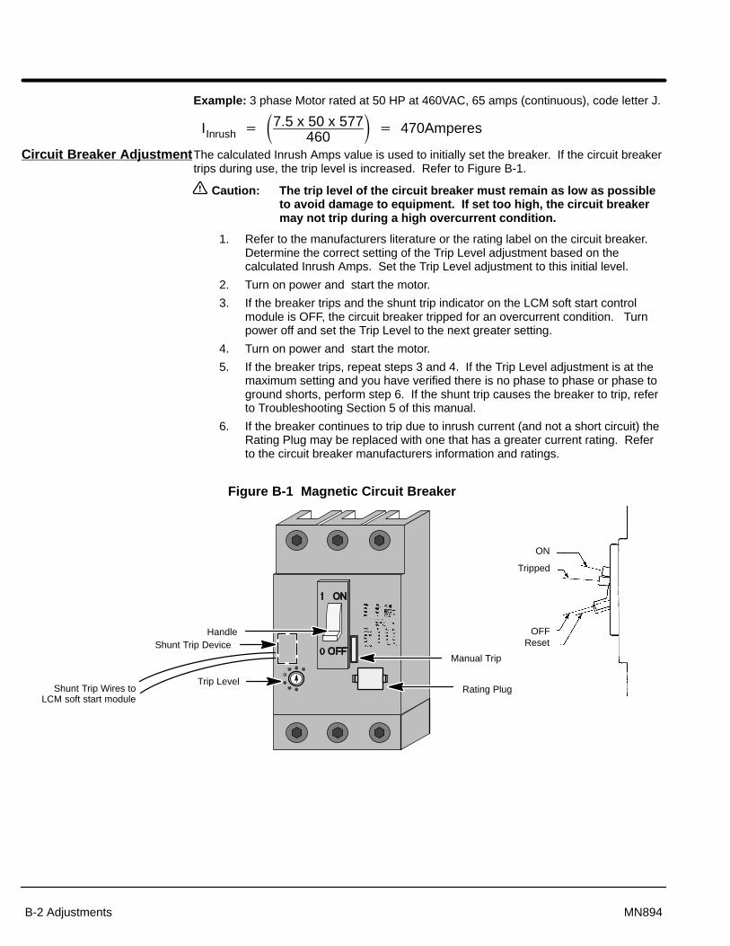
Section 1General Information
B-2 Adjustments MN894
Example: 3 phase Motor rated at 50 HP at 460VAC, 65 amps (continuous), code letter J.
IInrush � �7.5 x 50 x 577460
� � 470Amperes
Circuit Breaker AdjustmentThe calculated Inrush Amps value is used to initially set the breaker. If the circuit breakertrips during use, the trip level is increased. Refer to Figure B-1.
Caution: The trip level of the circuit breaker must remain as low as possibleto avoid damage to equipment. If set too high, the circuit breakermay not trip during a high overcurrent condition.
1. Refer to the manufacturers literature or the rating label on the circuit breaker.Determine the correct setting of the Trip Level adjustment based on thecalculated Inrush Amps. Set the Trip Level adjustment to this initial level.
2. Turn on power and start the motor.
3. If the breaker trips and the shunt trip indicator on the LCM soft start controlmodule is OFF, the circuit breaker tripped for an overcurrent condition. Turnpower off and set the Trip Level to the next greater setting.
4. Turn on power and start the motor.
5. If the breaker trips, repeat steps 3 and 4. If the Trip Level adjustment is at themaximum setting and you have verified there is no phase to phase or phase toground shorts, perform step 6. If the shunt trip causes the breaker to trip, referto Troubleshooting Section 5 of this manual.
6. If the breaker continues to trip due to inrush current (and not a short circuit) theRating Plug may be replaced with one that has a greater current rating. Referto the circuit breaker manufacturers information and ratings.
Figure B-1 Magnetic Circuit Breaker
ON
Tripped
OFFReset
Handle
Rating Plug
Manual Trip
Trip Level
Shunt Trip Device
Shunt Trip Wires toLCM soft start module

BALDOR ELECTRIC COMPANYP.O. Box 2400
Ft. Smith, AR 72902–2400(501) 646–4711
Fax (501) 648–5792
Baldor Electric CompanyMN894
Printed in USA4/01 C&J 1500


